EP1767918A1 - Blower for a laser oscillator and laser oscillator using the same - Google Patents
Blower for a laser oscillator and laser oscillator using the same Download PDFInfo
- Publication number
- EP1767918A1 EP1767918A1 EP06019251A EP06019251A EP1767918A1 EP 1767918 A1 EP1767918 A1 EP 1767918A1 EP 06019251 A EP06019251 A EP 06019251A EP 06019251 A EP06019251 A EP 06019251A EP 1767918 A1 EP1767918 A1 EP 1767918A1
- Authority
- EP
- European Patent Office
- Prior art keywords
- blower
- vibration
- abnormal
- casing
- sensors
- Prior art date
- Legal status (The legal status is an assumption and is not a legal conclusion. Google has not performed a legal analysis and makes no representation as to the accuracy of the status listed.)
- Withdrawn
Links
- 230000002159 abnormal effect Effects 0.000 claims abstract description 64
- 230000005856 abnormality Effects 0.000 description 11
- CURLTUGMZLYLDI-UHFFFAOYSA-N Carbon dioxide Chemical compound O=C=O CURLTUGMZLYLDI-UHFFFAOYSA-N 0.000 description 6
- 229910002092 carbon dioxide Inorganic materials 0.000 description 3
- 239000001569 carbon dioxide Substances 0.000 description 3
- 238000001514 detection method Methods 0.000 description 2
- 239000012535 impurity Substances 0.000 description 2
- 238000012423 maintenance Methods 0.000 description 2
- 239000000126 substance Substances 0.000 description 2
- 238000005299 abrasion Methods 0.000 description 1
- 238000007792 addition Methods 0.000 description 1
- 238000004891 communication Methods 0.000 description 1
- 239000000498 cooling water Substances 0.000 description 1
- 238000007599 discharging Methods 0.000 description 1
- 230000000694 effects Effects 0.000 description 1
- 238000005286 illumination Methods 0.000 description 1
- 238000000034 method Methods 0.000 description 1
- 230000003287 optical effect Effects 0.000 description 1
- 238000011282 treatment Methods 0.000 description 1
Images

Classifications
-
- H—ELECTRICITY
- H01—ELECTRIC ELEMENTS
- H01S—DEVICES USING THE PROCESS OF LIGHT AMPLIFICATION BY STIMULATED EMISSION OF RADIATION [LASER] TO AMPLIFY OR GENERATE LIGHT; DEVICES USING STIMULATED EMISSION OF ELECTROMAGNETIC RADIATION IN WAVE RANGES OTHER THAN OPTICAL
- H01S3/00—Lasers, i.e. devices using stimulated emission of electromagnetic radiation in the infrared, visible or ultraviolet wave range
- H01S3/02—Constructional details
- H01S3/03—Constructional details of gas laser discharge tubes
- H01S3/036—Means for obtaining or maintaining the desired gas pressure within the tube, e.g. by gettering, replenishing; Means for circulating the gas, e.g. for equalising the pressure within the tube
-
- G—PHYSICS
- G01—MEASURING; TESTING
- G01H—MEASUREMENT OF MECHANICAL VIBRATIONS OR ULTRASONIC, SONIC OR INFRASONIC WAVES
- G01H1/00—Measuring characteristics of vibrations in solids by using direct conduction to the detector
- G01H1/003—Measuring characteristics of vibrations in solids by using direct conduction to the detector of rotating machines
-
- G—PHYSICS
- G01—MEASURING; TESTING
- G01M—TESTING STATIC OR DYNAMIC BALANCE OF MACHINES OR STRUCTURES; TESTING OF STRUCTURES OR APPARATUS, NOT OTHERWISE PROVIDED FOR
- G01M13/00—Testing of machine parts
- G01M13/04—Bearings
- G01M13/045—Acoustic or vibration analysis
-
- H—ELECTRICITY
- H01—ELECTRIC ELEMENTS
- H01S—DEVICES USING THE PROCESS OF LIGHT AMPLIFICATION BY STIMULATED EMISSION OF RADIATION [LASER] TO AMPLIFY OR GENERATE LIGHT; DEVICES USING STIMULATED EMISSION OF ELECTROMAGNETIC RADIATION IN WAVE RANGES OTHER THAN OPTICAL
- H01S3/00—Lasers, i.e. devices using stimulated emission of electromagnetic radiation in the infrared, visible or ultraviolet wave range
- H01S3/05—Construction or shape of optical resonators; Accommodation of active medium therein; Shape of active medium
- H01S3/06—Construction or shape of active medium
- H01S3/07—Construction or shape of active medium consisting of a plurality of parts, e.g. segments
- H01S3/073—Gas lasers comprising separate discharge sections in one cavity, e.g. hybrid lasers
Definitions
- the present invention relates to a blower for a laser oscillator. More particularly, the present invention relates to a blower for a laser oscillator which is used for circulating a laser medium in a laser oscillator such as a chemical laser or gas laser, the laser medium of which is gas. Further, the present invention relates to a laser oscillator having such a blower.
- laser oscillators have been used in the fields of laser processing, medical treatment, illumination and communication. These laser oscillators include chemical laser oscillators and a gas laser oscillators in which a gas is used as a laser medium.
- a laser medium for example, carbon dioxide is circulated between an electric discharge tube and a heat exchanger so as to maintain the carbon dioxide laser medium at a proper temperature.
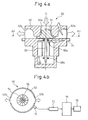
- Fig. 4a is a sectional view taken in the axial direction of a centrifugal type blower used for a laser oscillator of the prior art.
- Fig. 4b is a sectional view taken on line A1 - A1 in Fig. 4a.
- a suction port 52a and two exhaust ports 52b are formed in a casing 52 of a blower 50 of the prior art.
- the two exhaust ports 52b are arranged perpendicularly to the central axis O of the blower 50 and further directed in opposite directions.
- a blade 54 which is attached to a rotary shaft 55 of a drive motor 56 and rotatably supported about the central axis O, is provided in the casing 52.
- the rotary shaft 55 of the drive motor 56 is rotatably supported by two bearings 58a, 58b.
- the above blower 50 incorporated in the laser oscillator is usually rotated at a speed of not less than 10,000 rpm. Accordingly, in the case where the blower 50 is used over a long period of time, the bearings 58a, 58b are abraded. Due to the abrasion, the bearings 58a, 58b and the rotary shaft 55 may suddenly seize and be broken, in some cases. In this case, impurities flow into a resonator through a portion at which the broken bearings are located. Accordingly, not only the inside of the resonator is polluted but, also, the laser oscillator can not be restarted. In order to restore the laser oscillator to its original state, it is necessary to replace the bearings 58a, 58b and others and further it is necessary to discharge the impurities from the inside of the resonator, which takes a long time.
- a single vibration sensor 71 for detecting vibration of the blower 50 is attached to the blower 50 of the prior art disclosed in Japanese Unexamined Patent publication No. 5-90661 .
- a vibration detection signal sent from the vibration sensor 71 is amplified by an amplifier 73 and supplied to an alarm judging means 75.
- the alarm judging means 75 it is judged whether or not a peak value of the vibration detection signal, which is amplified by the amplifier 73, exceeds a threshold value.
- an alarm is outputted from an alarm device 76. Accordingly, by repairing or replacing broken bearings and others after the alarm has been outputted, it is possible to prevent the bearings 58a, 58b of the drive motor 56 from being seized and broken.
- a blower disclosed in Japanese Unexamined Patent Publication No. 11-87820 includes a motor current detector for detecting a motor current flowing in a drive motor. In the case where the intensity of the motor current detected by the motor current detector suddenly increases and, for example, in the case where an intensity of the motor current detected by the motor current detector exceeds a threshold value, it is judged that the blower life is nearly ended, and an alarm is outputted.
- vibration and/or noise is detected at a portion other than the bearings 58a, 58b which tend to be damaged. Further, vibration and/or noise, which is transmitted from the outside of the blower, is detected in some cases.
- the blower disclosed in Japanese Unexamined Patent Publication No. 5-90661 includes only one vibration sensor 71. In this structure, it is impossible to specify the source of abnormal vibration. Accordingly, it is possible to encounter the following circumstances. In the case where the source of vibration and/or noise exists outside the blower, even if the blower is disassembled after the alarm has been outputted, no problems are found at the bearings arranged in the blower.
- the present invention has been accomplished in view of the above circumstances. It is an object of the present invention to provide a blower for a laser oscillator capable of specifying the position where an abnormality has occurred so that a countermeasure can be taken against the abnormality. It is another object of the present invention to provide a laser oscillator into which the blower is incorporated.
- the first aspect provides a blower comprising: a casing in which a suction port and at least one exhaust port are formed; a drive motor having a rotary shaft rotated via bearings in the casing; a blade rotatably supported about the rotary shaft in the casing in such a manner that the blade faces the suction port and the exhaust port; at least two acoustic sensors or vibration sensors attached to the casing; and a position specifying means for specifying a position of a source of abnormal sound or abnormal vibration from a signal detected by the acoustic sensors or vibration sensors.
- a source abnormal sound and others can be specified by the position specifying means, that is, it is possible to specify a two-dimensional position of the abnormal portion. An operator can judge that this two-dimensional position is a portion to be replaced or repaired. Therefore, it is possible for the operator to quickly take a proper countermeasure against the abnormality. Accordingly, it becomes possible to enhance the reliability and the maintenance of the blower.
- the second aspect provides a blower comprising: a casing in which a suction port and at least one exhaust port are formed; a drive motor having a rotary shaft rotated via bearings in the casing; a blade rotatably supported about the rotary shaft in the casing in such a manner that the blade faces the suction port and the exhaust port; at least three acoustic sensors or vibration sensors attached to the casing; and a position specifying means for specifying a position of a source of abnormal sound or abnormal vibration from a signal detected by the acoustic sensors or vibration sensors.
- a position of the source of generating the abnormal sound can be specified by the position specifying means, that is, it is possible to specify a three-dimensional position of the abnormal portion. An operator can judge that this three-dimensional position is a portion to be replaced or repaired. Therefore, it is possible for the operator to quickly take a proper countermeasure against the abnormality. Accordingly, it becomes possible to enhance the reliability and the maintenance of the blower.
- a blower of the first or the second aspect further comprises an alarm output judging means for judging whether or not an alarm is to be outputted according to a position, of a source at which the abnormal sound or abnormal vibration is generated, specified by the position specifying means.
- a source of generating abnormal sound in the case where a source of generating abnormal sound is located in a portion which affects the reliability of the blower, for example, in the case where a source of generating abnormal sound is located at the bearing arranged in the blower, an alarm is outputted, so that the blower can be previously prevented from being damaged.
- a source of generating abnormal sound is located in a portion which does not affect the reliability of the blower, for example, in the case where a source of generating abnormal sound is located in an external member of the blower, no alarm is outputted, so that a rate of operation of the blower is not lowered.
- the distances between the respective acoustic sensors or vibration sensors, which are attached to the casing, and the rotary shaft are equal.
- the position specifying means for specifying a position of a source of the abnormal sound or abnormal vibration, specifies the position of the source of the abnormal sound or abnormal vibration by a time difference of signals or by a phase difference of signal wave-forms sent from the acoustic sensors or vibration sensors and by a mutual correlation with respect to the signal, the time difference and the phase difference.
- a two-dimensional position or a three-dimensional position of the abnormal portion can be properly specified.
- the sixth aspect provides a laser oscillator comprising a blower according to one of the first to the fifth aspects.
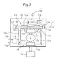
- a laser oscillator having a blower of the present invention will be explained as follows.
- a gas laser oscillator of a relatively high output which is of the induction-discharge-exciting-type, is shown.
- a carbon dioxide gas laser oscillator 100 is shown.
- the laser oscillator 100 includes: a discharge tube 102; and a circulation passage 104 including a suction pipe 104a for sucking a laser medium, which is gas, from substantially a central portion in the longitudinal direction of the discharge tube 102 and a return pipe 104b for discharging the laser medium to portions of the discharge tube 102 adjacent to both end portions of the same.
- a forward end portion of the discharge tube 102 an output mirror 106 is arranged.
- a rear mirror 108 is arranged. Therefore, an optical resonance space is formed between the output mirror 106 and the rear mirror 108.
- a laser power sensor 110 is arranged at the rear of the rear mirror 108.
- a first discharge section 112 which includes discharge electrodes 112a, 112b arranged opposed to each other with respect to the discharge tube 102.
- the first discharge section 112 is connected to a laser electric power source 118 via a matching circuit 116.
- a second discharge section 114 is provided which includes discharge electrodes 114a, 114b arranged opposed to each other with respect to the discharge tube 102.
- the second discharge section 114 is also connected to a laser electric power source via a matching circuit in the same manner as that described above.
- a blower 120 for circulating the laser medium is arranged in the suction pipe 104a of the circulating passage 104.
- a first and a second heat exchanger 122, 124 are respectively arranged on the suction side and the discharge side of the blower 120 in the suction pipe 104a of the circulating passage 104.
- a gas supply tube 128 and a gas discharge tube 130 are respectively connected to the return pipes 104b of the circulating passage 104 through a gas pressure control device 126.
- the gas pressure control device 126 controls the discharge and supply of the laser gas so that the pressure in the discharge tube 102 and in the circulating passage 104 can be maintained at a proper value.
- the above components of the laser oscillator can be housed in the casing 132.
- the laser oscillator 100 is connected to a cooling water system 134 provided outside the casing 132. Therefore, the laser medium can be appropriately cooled through the heat exchangers 122, 124 so as to maintain the temperature of the laser medium at a proper value.
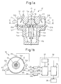
- Fig. 1a is a sectional view taken in the axial direction of a blower for a laser oscillator of the present invention.
- Fig. 1b is a sectional view taken on line A - A in Fig. 1a.
- the blower 10 shown in Figs. 1a and 1b is the same as the blower 120 shown in Fig. 2 which is used for the laser oscillator 100.
- the blower 10 includes a substantially cylindrical casing 12 in which one suction port 12a and two exhaust ports 12b are formed. As shown in Fig. 1b, these exhaust ports 12b are formed perpendicularly to the central axis O and in the opposite direction to each other.
- a drive motor 14 arranged in the casing 12 includes: a rotary shaft 14a extending along the central axis O of the casing 12; a rotor 14b fixed to the rotary shaft 14a; and a stator 14c which faces the rotor 14b and is fixed onto an inner face of the casing 12.
- the rotary shaft 14a is rotatably supported by bearings 16a, 16b arranged in the casing 12.
- a blade 18 is arranged at a forward end portion of the rotary shaft 14a.
- vibration sensors 31, 31b, 31c are attached to an outer circumferential portion of the casing 12. These vibration sensors 31, 31b, 31c are attached at regular intervals in the circumferential direction right below the exhaust ports 12b. Accordingly, distances from the respective vibration sensors 31a, 31b, 31c to the rotary shaft 14a are equal to each other. It is preferable that the vibration sensors 31a, 31b, 31c are attached at the same height as shown in the drawing. However, these vibration sensors 31a, 31b, 31c may be respectively attached at positions, the heights of which are different.
- the respective vibration sensors 31a, 31b, 31c are connected to the corresponding amplifiers 33a, 33b, 33c. Further, these amplifiers 33a, 33b, 33c are connected to a control unit 30 for controlling the laser oscillator 100 including the blower 10.
- the control unit 30 includes: a position specifying means 34 for specifying the position of a source of abnormal vibration; an alarm output judging means 35 for judging whether or not an alarm is outputted from the alarm device 36; and a storage means 37 such as a memory. Strictly speaking, the amplifiers 33a, 33b, 33c are connected to the position specifying means 34 of the control unit 30.
- the storage means 37 stores a judging program (described later) of the alarm output judging means 35 in addition to the precise dimensional data of the blower 10.
- vibration sensors 31a, 31b, 31c attached to the casing 12 always detect vibration generated at the time of operation of the blower 10. Vibration signals sa, sb, sc, which are produced by the vibration sensors 31a, 31b, 31c, are amplified by the corresponding amplifiers 33a, 33b, 33c. After that, the vibration signals are supplied to the position specifying means 34 of the control unit 30 as amplified vibration signals S a , S b , S c .
- the vibration signals S a , S b , S c are in a predetermined range.
- the vibration signals S a , S b , S c exceed a predetermined range, that is, in the case where an abnormal vibration is detected, the position specifying means 34 conducts the following process.
- the position specifying means 34 calculates a time difference among the vibration signals S a , S b , S c and also calculates a phase difference among the wave-shapes of the vibration signals S a , S b , S c . Further, the position specifying means 34 conducts statistical processing by a cross-correlation with respect to the vibration signals, the time differences and the phase differences. A result obtained by the statistical processing is calculated with a predetermined calculating expression in relation to the dimensional data of the blower 10 stored in the storage means 37. According to the result of the calculation, a three-dimensional position of the source of generating the abnormal vibration can be specified.
- the three vibration sensors 31a, 31b, 31c are attached to the outer circumference of the casing 12 at regular intervals and at the same height, the three-dimensional position of the source of the abnormal vibration can be easily specified.
- the three-dimensional position or the two-dimensional position of the source of the abnormal vibration that is, the positional information of the source of the abnormal vibration is supplied to the alarm output judging means 35.
- the alarm output judging means 35 supplies an alarm output command to the alarm device 36. Therefore, an alarm is outputted from the alarm device 36. It is preferable that the positional information of the abnormal portion is simultaneously outputted at this time onto a monitor not shown. Due to the foregoing, a portion to be replaced or repaired is indicated to an operator. Therefore, it is possible for the operator to quickly take a proper appropriate countermeasure against the problem.
- the alarm output judging means 35 may judge whether or not an alarm is outputted according to the positional information of the source of the abnormal vibration.
- Fig. 3 is a flow chart of a judgment program of the alarm output judging means 35 used in this case.
- step 201 of the program 200 shown in Fig. 3 it is judged whether or not abnormal vibration is generated, that is, whether or not the positional information of abnormal vibration is supplied to the alarm output judging means 35.
- the program proceeds to step 204 and finishes without outputting an alarm.
- the program proceeds to step 202. Then, it is judged according to the positional information of the abnormal vibration whether or not the source of the abnormal vibration is located inside the blower 10. This can be easily judged by comparing the dimensional data of the blower 10 stored in the storage means 37 with the positional information.
- the program proceeds to step 203, and an alarm is outputted from the alarm device 36.
- the bearing 16a arranged inside the blower 10 has a great influence on the reliability of the blower 10, in the case where the bearing 16a is an abnormal portion, an alarm is outputted so that an operator can note the occurrence of an abnormality in the bearing 16a. Due to the foregoing, it is possible for the operator to prevent the blower from being damaged. In the case described above, it is possible for the operator to check the blower 10 before the bearing is broken. Therefore, the laser oscillator 100 will not have been polluted and the blower 10 can be repaired in a relatively short period of time.
- the program proceeds to step 204. Then, the program finishes without outputting an alarm. That is, in the case where an abnormal vibration is generated from an external device located outside the blower 10, this abnormal vibration does not influence the reliability of the blower 10. Therefore, it is preferable that no alarm is outputted in this case. Accordingly, the rate of operation of the blower is not lowered.
- an abnormality is generated in the external device. Therefore, in the case where the source of generating an abnormal vibration is not located inside the blower 10, an alarm different from the alarm of step 203 may be outputted. In this way, the abnormal vibration of the external device arranged outside the blower 10 can be indicated to the operator.
- the source of the abnormal vibration is specified by the vibration sensor.
- an acoustic sensor is used to specify the source of abnormal noise, instead of the vibration sensor. It is clear that the same effect as that described above can be provided in this case.
Landscapes
- Physics & Mathematics (AREA)
- General Physics & Mathematics (AREA)
- Electromagnetism (AREA)
- Acoustics & Sound (AREA)
- Engineering & Computer Science (AREA)
- Plasma & Fusion (AREA)
- Optics & Photonics (AREA)
- Structures Of Non-Positive Displacement Pumps (AREA)
- Lasers (AREA)
- Control Of Positive-Displacement Air Blowers (AREA)
Abstract
Description
- The present invention relates to a blower for a laser oscillator. More particularly, the present invention relates to a blower for a laser oscillator which is used for circulating a laser medium in a laser oscillator such as a chemical laser or gas laser, the laser medium of which is gas. Further, the present invention relates to a laser oscillator having such a blower.
- Recently, laser oscillators have been used in the fields of laser processing, medical treatment, illumination and communication. These laser oscillators include chemical laser oscillators and a gas laser oscillators in which a gas is used as a laser medium. In the gas laser oscillator, a laser medium, for example, carbon dioxide is circulated between an electric discharge tube and a heat exchanger so as to maintain the carbon dioxide laser medium at a proper temperature.
- Fig. 4a is a sectional view taken in the axial direction of a centrifugal type blower used for a laser oscillator of the prior art. Fig. 4b is a sectional view taken on line A1 - A1 in Fig. 4a. As shown in Fig. 4a, in a
casing 52 of ablower 50 of the prior art, asuction port 52a and twoexhaust ports 52b are formed. As shown in the drawing, the twoexhaust ports 52b are arranged perpendicularly to the central axis O of theblower 50 and further directed in opposite directions. Further, ablade 54, which is attached to arotary shaft 55 of adrive motor 56 and rotatably supported about the central axis O, is provided in thecasing 52. Therotary shaft 55 of thedrive motor 56 is rotatably supported by twobearings - The
above blower 50 incorporated in the laser oscillator is usually rotated at a speed of not less than 10,000 rpm. Accordingly, in the case where theblower 50 is used over a long period of time, thebearings bearings rotary shaft 55 may suddenly seize and be broken, in some cases. In this case, impurities flow into a resonator through a portion at which the broken bearings are located. Accordingly, not only the inside of the resonator is polluted but, also, the laser oscillator can not be restarted. In order to restore the laser oscillator to its original state, it is necessary to replace thebearings - In order to solve the above problems, a
single vibration sensor 71 for detecting vibration of theblower 50 is attached to theblower 50 of the prior art disclosed inJapanese Unexamined Patent publication No. 5-90661 vibration sensor 71 is amplified by anamplifier 73 and supplied to an alarm judging means 75. In the alarm judging means 75, it is judged whether or not a peak value of the vibration detection signal, which is amplified by theamplifier 73, exceeds a threshold value. When a number of times, in which the peak value exceeds the threshold value, exceeds a predetermined number, an alarm is outputted from analarm device 76. Accordingly, by repairing or replacing broken bearings and others after the alarm has been outputted, it is possible to prevent thebearings drive motor 56 from being seized and broken. - A blower disclosed in
Japanese Unexamined Patent Publication No. 11-87820 - However, in some cases vibration and/or noise is detected at a portion other than the
bearings Japanese Unexamined Patent Publication No. 5-90661 vibration sensor 71. In this structure, it is impossible to specify the source of abnormal vibration. Accordingly, it is possible to encounter the following circumstances. In the case where the source of vibration and/or noise exists outside the blower, even if the blower is disassembled after the alarm has been outputted, no problems are found at the bearings arranged in the blower. - In the case of the blower disclosed in
Japanese Unexamined Patent Publication No. 11-87820 - That is, in the cases described in
Japanese Unexamined Patent Publication No. 5-90661 Japanese Unexamined Patent Publication No. 11-87820 - The present invention has been accomplished in view of the above circumstances. It is an object of the present invention to provide a blower for a laser oscillator capable of specifying the position where an abnormality has occurred so that a countermeasure can be taken against the abnormality. It is another object of the present invention to provide a laser oscillator into which the blower is incorporated.
- In order to accomplish the above object, the first aspect provides a blower comprising: a casing in which a suction port and at least one exhaust port are formed; a drive motor having a rotary shaft rotated via bearings in the casing; a blade rotatably supported about the rotary shaft in the casing in such a manner that the blade faces the suction port and the exhaust port; at least two acoustic sensors or vibration sensors attached to the casing; and a position specifying means for specifying a position of a source of abnormal sound or abnormal vibration from a signal detected by the acoustic sensors or vibration sensors.
- That is, in the first aspect, from the signals detected by the acoustic sensors or the vibration sensors, a source abnormal sound and others can be specified by the position specifying means, that is, it is possible to specify a two-dimensional position of the abnormal portion. An operator can judge that this two-dimensional position is a portion to be replaced or repaired. Therefore, it is possible for the operator to quickly take a proper countermeasure against the abnormality. Accordingly, it becomes possible to enhance the reliability and the maintenance of the blower.
- The second aspect provides a blower comprising: a casing in which a suction port and at least one exhaust port are formed; a drive motor having a rotary shaft rotated via bearings in the casing; a blade rotatably supported about the rotary shaft in the casing in such a manner that the blade faces the suction port and the exhaust port; at least three acoustic sensors or vibration sensors attached to the casing; and a position specifying means for specifying a position of a source of abnormal sound or abnormal vibration from a signal detected by the acoustic sensors or vibration sensors.
- That is, in the second aspect, with the signals detected by the acoustic sensors or the vibration sensors, a position of the source of generating the abnormal sound can be specified by the position specifying means, that is, it is possible to specify a three-dimensional position of the abnormal portion. An operator can judge that this three-dimensional position is a portion to be replaced or repaired. Therefore, it is possible for the operator to quickly take a proper countermeasure against the abnormality. Accordingly, it becomes possible to enhance the reliability and the maintenance of the blower.
- According to the third aspect, a blower of the first or the second aspect further comprises an alarm output judging means for judging whether or not an alarm is to be outputted according to a position, of a source at which the abnormal sound or abnormal vibration is generated, specified by the position specifying means.
- In the third aspect, in the case where a source of generating abnormal sound is located in a portion which affects the reliability of the blower, for example, in the case where a source of generating abnormal sound is located at the bearing arranged in the blower, an alarm is outputted, so that the blower can be previously prevented from being damaged. On the other hand, in the case where a source of generating abnormal sound is located in a portion which does not affect the reliability of the blower, for example, in the case where a source of generating abnormal sound is located in an external member of the blower, no alarm is outputted, so that a rate of operation of the blower is not lowered.
- According to the fourth aspect, in one of the first to the third aspect, the distances between the respective acoustic sensors or vibration sensors, which are attached to the casing, and the rotary shaft are equal.
- That is, in the fourth aspect, in the case of the occurrence of an abnormality in the rotary body, which is a portion especially affecting the reliability of the device, it is possible to accurately specify a three-dimensional position of the abnormal portion.
- According to the fifth aspect, in one of the first to the fourth aspect, the position specifying means, for specifying a position of a source of the abnormal sound or abnormal vibration, specifies the position of the source of the abnormal sound or abnormal vibration by a time difference of signals or by a phase difference of signal wave-forms sent from the acoustic sensors or vibration sensors and by a mutual correlation with respect to the signal, the time difference and the phase difference.
- That is, in the fifth aspect, a two-dimensional position or a three-dimensional position of the abnormal portion can be properly specified.
- The sixth aspect provides a laser oscillator comprising a blower according to one of the first to the fifth aspects.
- The objects, characteristics and advantages of the present invention will become apparent from the detailed explanations of the typical embodiment of the present invention shown in the accompanying drawings.
-
- Fig. 1a is a sectional view taken in the axial direction of a blower for a laser oscillator of the present invention.
- Fig. 1b is a sectional view taken on line A - A in Fig. 1a.
- Fig. 2 is a schematic drawing of a laser oscillator having a blower of the present invention.
- Fig. 3 is a flow chart of a judgment program of an alarm output judging means provided in a blower of the present invention.
- Fig. 4a is a sectional view taken in the axial direction of a blower for a laser oscillator of the prior art.
- Fig. 4b is a sectional view taken on line A1 - A1 in Fig. 4a.
- Referring to the accompanying drawings, an embodiment of the present invention will be explained below. In the following drawings, like reference characters are used to indicate like parts. In order to facilitate the understanding, the scale is appropriately changed in these drawings.
- First of all, referring to Fig. 2, a laser oscillator having a blower of the present invention will be explained as follows. In Fig. 2, as an example of the laser oscillator to which the present invention is applied, a gas laser oscillator of a relatively high output, which is of the induction-discharge-exciting-type, is shown. For example, a carbon dioxide
gas laser oscillator 100 is shown. Thelaser oscillator 100 includes: adischarge tube 102; and acirculation passage 104 including asuction pipe 104a for sucking a laser medium, which is gas, from substantially a central portion in the longitudinal direction of thedischarge tube 102 and areturn pipe 104b for discharging the laser medium to portions of thedischarge tube 102 adjacent to both end portions of the same. At a forward end portion of thedischarge tube 102, anoutput mirror 106 is arranged. At a rear end portion of thedischarge tube 102, arear mirror 108 is arranged. Therefore, an optical resonance space is formed between theoutput mirror 106 and therear mirror 108. At the rear of therear mirror 108, alaser power sensor 110 is arranged. - In a portion of the
discharge tube 102 adjacent to therear mirror 108, a first discharge section 112 is provided which includesdischarge electrodes 112a, 112b arranged opposed to each other with respect to thedischarge tube 102. The first discharge section 112 is connected to a laserelectric power source 118 via amatching circuit 116. Further, in a portion of thedischarge tube 102 adjacent to theoutput mirror 106, asecond discharge section 114 is provided which includesdischarge electrodes 114a, 114b arranged opposed to each other with respect to thedischarge tube 102. In this connection, although not particularly shown in Fig. 2, thesecond discharge section 114 is also connected to a laser electric power source via a matching circuit in the same manner as that described above. - In the
suction pipe 104a of the circulatingpassage 104, ablower 120 for circulating the laser medium is arranged. On the suction side and the discharge side of theblower 120 in thesuction pipe 104a of the circulatingpassage 104, a first and asecond heat exchanger 122, 124 are respectively arranged. Agas supply tube 128 and agas discharge tube 130 are respectively connected to thereturn pipes 104b of the circulatingpassage 104 through a gaspressure control device 126. The gaspressure control device 126 controls the discharge and supply of the laser gas so that the pressure in thedischarge tube 102 and in the circulatingpassage 104 can be maintained at a proper value. - The above components of the laser oscillator can be housed in the
casing 132. Thelaser oscillator 100 is connected to acooling water system 134 provided outside thecasing 132. Therefore, the laser medium can be appropriately cooled through theheat exchangers 122, 124 so as to maintain the temperature of the laser medium at a proper value. - Fig. 1a is a sectional view taken in the axial direction of a blower for a laser oscillator of the present invention. Fig. 1b is a sectional view taken on line A - A in Fig. 1a. Referring to these drawings, the blower of the present invention will be explained below. The
blower 10 shown in Figs. 1a and 1b is the same as theblower 120 shown in Fig. 2 which is used for thelaser oscillator 100. Theblower 10 includes a substantiallycylindrical casing 12 in which onesuction port 12a and twoexhaust ports 12b are formed. As shown in Fig. 1b, theseexhaust ports 12b are formed perpendicularly to the central axis O and in the opposite direction to each other. - A
drive motor 14 arranged in thecasing 12 includes: arotary shaft 14a extending along the central axis O of thecasing 12; a rotor 14b fixed to therotary shaft 14a; and a stator 14c which faces the rotor 14b and is fixed onto an inner face of thecasing 12. As shown in the drawing, therotary shaft 14a is rotatably supported bybearings casing 12. At a forward end portion of therotary shaft 14a, ablade 18 is arranged. - As can be seen in Figs. 1a and 1b, in the present invention, three
vibration sensors casing 12. Thesevibration sensors exhaust ports 12b. Accordingly, distances from therespective vibration sensors rotary shaft 14a are equal to each other. It is preferable that thevibration sensors vibration sensors - As shown in Fig. 1b, the
respective vibration sensors amplifiers amplifiers control unit 30 for controlling thelaser oscillator 100 including theblower 10. As shown in the drawing, thecontrol unit 30 includes: a position specifying means 34 for specifying the position of a source of abnormal vibration; an alarm output judging means 35 for judging whether or not an alarm is outputted from thealarm device 36; and a storage means 37 such as a memory. Strictly speaking, theamplifiers control unit 30. The storage means 37 stores a judging program (described later) of the alarm output judging means 35 in addition to the precise dimensional data of theblower 10. - At the time of operation of the
blower 10, by rotating theblade 18, gas is sucked from thesuction port 12a along the central axis O as shown by the arrow Fi. At the same time, the thus sucked gas is discharged from the twoexhaust ports 12b as shown by the arrow Fo. Thevibration sensors casing 12 always detect vibration generated at the time of operation of theblower 10. Vibration signals sa, sb, sc, which are produced by thevibration sensors amplifiers control unit 30 as amplified vibration signals Sa, Sb, Sc. - When the
blower 10 operates normally, the vibration signals Sa, Sb, Sc are in a predetermined range. However, in the case where the vibration signals Sa, Sb, Sc exceed a predetermined range, that is, in the case where an abnormal vibration is detected, the position specifying means 34 conducts the following process. - The position specifying means 34 calculates a time difference among the vibration signals Sa, Sb, Sc and also calculates a phase difference among the wave-shapes of the vibration signals Sa, Sb, Sc. Further, the position specifying means 34 conducts statistical processing by a cross-correlation with respect to the vibration signals, the time differences and the phase differences. A result obtained by the statistical processing is calculated with a predetermined calculating expression in relation to the dimensional data of the
blower 10 stored in the storage means 37. According to the result of the calculation, a three-dimensional position of the source of generating the abnormal vibration can be specified. Especially, in the embodiment shown in the drawing, as the threevibration sensors casing 12 at regular intervals and at the same height, the three-dimensional position of the source of the abnormal vibration can be easily specified. In this connection, it is possible to adopt a structure in which two vibration sensors are attached to the outer circumference of thecasing 12 at the same height. Even in this structure, it is possible to specify a two-dimensional position with respect to the source of the abnormal vibration. - The three-dimensional position or the two-dimensional position of the source of the abnormal vibration, that is, the positional information of the source of the abnormal vibration is supplied to the alarm output judging means 35. When the positional information of the abnormal vibration is supplied, the alarm output judging means 35 supplies an alarm output command to the
alarm device 36. Therefore, an alarm is outputted from thealarm device 36. It is preferable that the positional information of the abnormal portion is simultaneously outputted at this time onto a monitor not shown. Due to the foregoing, a portion to be replaced or repaired is indicated to an operator. Therefore, it is possible for the operator to quickly take a proper appropriate countermeasure against the problem. - The alarm output judging means 35 may judge whether or not an alarm is outputted according to the positional information of the source of the abnormal vibration. Fig. 3 is a flow chart of a judgment program of the alarm output judging means 35 used in this case. In
step 201 of theprogram 200 shown in Fig. 3, it is judged whether or not abnormal vibration is generated, that is, whether or not the positional information of abnormal vibration is supplied to the alarm output judging means 35. In the case where no abnormal vibration is generated, the program proceeds to step 204 and finishes without outputting an alarm. - On the other hand, in the case where abnormal vibration is generated, the program proceeds to step 202. Then, it is judged according to the positional information of the abnormal vibration whether or not the source of the abnormal vibration is located inside the
blower 10. This can be easily judged by comparing the dimensional data of theblower 10 stored in the storage means 37 with the positional information. In the case where the source of the abnormal vibration is located inside theblower 10 and, for example, in the case where the abnormal vibration V1 is generated from thebearing 16a as shown in Fig. 1a, the program proceeds to step 203, and an alarm is outputted from thealarm device 36. - As the
bearing 16a arranged inside theblower 10 has a great influence on the reliability of theblower 10, in the case where thebearing 16a is an abnormal portion, an alarm is outputted so that an operator can note the occurrence of an abnormality in thebearing 16a. Due to the foregoing, it is possible for the operator to prevent the blower from being damaged. In the case described above, it is possible for the operator to check theblower 10 before the bearing is broken. Therefore, thelaser oscillator 100 will not have been polluted and theblower 10 can be repaired in a relatively short period of time. - On the other hand, in the case where the source of the abnormal vibration is not located inside the
blower 10, for example, in the case where the abnormal vibration V2 (shown in Fig. 1a) is generated from an external device (not shown) located outside theblower 10, the program proceeds to step 204. Then, the program finishes without outputting an alarm. That is, in the case where an abnormal vibration is generated from an external device located outside theblower 10, this abnormal vibration does not influence the reliability of theblower 10. Therefore, it is preferable that no alarm is outputted in this case. Accordingly, the rate of operation of the blower is not lowered. - However, in this case, there is a high possibility that an abnormality is generated in the external device. Therefore, in the case where the source of generating an abnormal vibration is not located inside the
blower 10, an alarm different from the alarm ofstep 203 may be outputted. In this way, the abnormal vibration of the external device arranged outside theblower 10 can be indicated to the operator. - In the embodiment explained above by referring to the drawings, the source of the abnormal vibration is specified by the vibration sensor. However, it is possible to adopt a structure, in which an acoustic sensor is used to specify the source of abnormal noise, instead of the vibration sensor. It is clear that the same effect as that described above can be provided in this case.
- The present invention has been explained above by the typical embodiment. However, it can be understood that variations, omissions and additions may be made, by those skilled in the art, without departing from the scope of the claims of the present invention.
Claims (6)
- A blower comprising:a casing (12) in which a suction port (12a) and at least one exhaust port (12b) are formed;a drive motor (14) having a rotary shaft (14a) rotating via bearings (16a, 16b) in the casing (12); anda blade (18) rotatably supported about the rotary shaft (14a) in the casing (12) in such a manner that the blade (18) faces the suction port (12a) and the exhaust port (12b),the blower (10) further comprising:at least two acoustic sensors or vibration sensors (31a, 31b, 31c) attached to the casing (12); anda position specifying means (34) for specifying a position of a source of abnormal sound or abnormal vibration (V1, V2) from a signal detected by the acoustic sensors or vibration sensors (31a, 31b, 31c).
- A blower comprising:a casing (12) in which a suction port (12a) and at least one exhaust port (12b) are formed;a drive motor (14) having a rotary shaft (14a) rotating via bearings (16a, 16b) in the casing (12); anda blade (18) rotatably supported about the rotary shaft (14a) in the casing (12) in such a manner that the blade (18) faces the suction port (12a) and the exhaust port (12b),the blower (10) further comprising:at least three acoustic sensors or vibration sensors (31a, 31b, 31c) attached to the casing (12); anda position specifying means (34) for specifying a position of a source of abnormal sound or abnormal vibration (V1, V2) from a signal detected by the acoustic sensors or vibration sensors (31a, 31b, 31c).
- A blower according to claim 1 or 2, further comprising an alarm output judging means (35) for judging whether or not an alarm is outputted according to the position of a source of the abnormal sound or abnormal vibration (V1, V2), specified by the position specifying means (34).
- A blower according to one of claims 1 to 3, wherein the distances between the respective acoustic sensors or vibration sensors (31a to 31c), which are attached to the casing (12), and the rotary shaft (14a) are equal.
- A blower according to one of claims 1 to 4, wherein the position specifying means (34) for specifying a position of a source of abnormal sound or abnormal vibration (V1, V2) specifies the position of the source of the abnormal sound or abnormal vibration (V1, V2) by the time difference between signals or by a phase difference between signal wave-forms sent from the acoustic sensors or vibration sensors (31a to 31c) or by and by a cross-correlation with respect to the signal, the time difference and the phase difference.
- A laser oscillator (100) comprising a blower (10) according to one of claims 1 to 5.
Applications Claiming Priority (1)
| Application Number | Priority Date | Filing Date | Title |
|---|---|---|---|
| JP2005278343A JP2007088380A (en) | 2005-09-26 | 2005-09-26 | Laser oscillator blower and laser oscillator |
Publications (1)
| Publication Number | Publication Date |
|---|---|
| EP1767918A1 true EP1767918A1 (en) | 2007-03-28 |
Family
ID=37478688
Family Applications (1)
| Application Number | Title | Priority Date | Filing Date |
|---|---|---|---|
| EP06019251A Withdrawn EP1767918A1 (en) | 2005-09-26 | 2006-09-14 | Blower for a laser oscillator and laser oscillator using the same |
Country Status (4)
| Country | Link |
|---|---|
| US (1) | US20070071057A1 (en) |
| EP (1) | EP1767918A1 (en) |
| JP (1) | JP2007088380A (en) |
| CN (1) | CN1945907A (en) |
Cited By (1)
| Publication number | Priority date | Publication date | Assignee | Title |
|---|---|---|---|---|
| CN101430244B (en) * | 2007-11-06 | 2012-10-31 | 大隈株式会社 | Bearing Condition Diagnosis Device |
Families Citing this family (10)
| Publication number | Priority date | Publication date | Assignee | Title |
|---|---|---|---|---|
| CN102318150B (en) * | 2009-02-24 | 2012-10-10 | 松下电器产业株式会社 | Gas laser oscillation device and gas laser processing machine |
| JP5494027B2 (en) * | 2010-03-05 | 2014-05-14 | パナソニック株式会社 | Laser oscillator |
| CN101872012A (en) * | 2010-06-11 | 2010-10-27 | 上海中科清洁能源技术发展中心 | Measuring and positioning system of equipment vibration source and method thereof |
| US9831510B2 (en) * | 2013-04-29 | 2017-11-28 | Audi Ag | Fuel cell system blower configuration |
| US9673685B2 (en) * | 2014-04-02 | 2017-06-06 | Rockwell Automation Technologies, Inc. | System and method for detection of motor vibration |
| US10260991B2 (en) | 2015-02-19 | 2019-04-16 | Nsk Ltd. | Abnormality diagnosis system |
| CN106679977A (en) * | 2017-01-03 | 2017-05-17 | 国电联合动力技术有限公司 | Wind turbine generator variable pitch bearing monitoring method and apparatus |
| CN107328581A (en) * | 2017-07-26 | 2017-11-07 | 安庆市鼎立汽车配件有限公司 | A kind of intelligent valve detecting system |
| CN107478394A (en) * | 2017-07-26 | 2017-12-15 | 安庆市鼎立汽车配件有限公司 | A kind of intelligent valve detection method based on timesharing analysis |
| EP3647597B1 (en) * | 2018-11-05 | 2021-11-03 | Grundfos Holding A/S | Sensor arrangement and method for monitoring a circulation pump system |
Citations (6)
| Publication number | Priority date | Publication date | Assignee | Title |
|---|---|---|---|---|
| US3783680A (en) * | 1972-07-12 | 1974-01-08 | Atomic Energy Commission | Multipoint vibration monitoring system |
| US4213346A (en) * | 1977-12-05 | 1980-07-22 | Masalov Gennady F | Method and apparatus for testing cyclically operated mechanical members for defects |
| EP0536415A1 (en) * | 1991-04-26 | 1993-04-14 | Fanuc Ltd. | Device for sensing abnormality in bearing of blower for gas laser |
| WO1996030649A1 (en) * | 1995-03-29 | 1996-10-03 | Leybold Vakuum Gmbh | Circulating blower, vacuum pump or the like |
| EP0800072A2 (en) * | 1996-04-04 | 1997-10-08 | Agency of Industrial Science and Technology of Ministry of International Trade and Industry | Method and apparatus for location of anomalous signal in a radial bearing |
| JPH1172377A (en) * | 1997-08-29 | 1999-03-16 | Sony Corp | Blower maintenance device and method for exhaust gas treatment system |
Family Cites Families (1)
| Publication number | Priority date | Publication date | Assignee | Title |
|---|---|---|---|---|
| JP2001352114A (en) * | 2000-06-08 | 2001-12-21 | Ebara Corp | Magnetic bearing device for excimer laser device |
-
2005
- 2005-09-26 JP JP2005278343A patent/JP2007088380A/en active Pending
-
2006
- 2006-09-14 EP EP06019251A patent/EP1767918A1/en not_active Withdrawn
- 2006-09-19 US US11/533,168 patent/US20070071057A1/en not_active Abandoned
- 2006-09-20 CN CNA2006101392320A patent/CN1945907A/en active Pending
Patent Citations (6)
| Publication number | Priority date | Publication date | Assignee | Title |
|---|---|---|---|---|
| US3783680A (en) * | 1972-07-12 | 1974-01-08 | Atomic Energy Commission | Multipoint vibration monitoring system |
| US4213346A (en) * | 1977-12-05 | 1980-07-22 | Masalov Gennady F | Method and apparatus for testing cyclically operated mechanical members for defects |
| EP0536415A1 (en) * | 1991-04-26 | 1993-04-14 | Fanuc Ltd. | Device for sensing abnormality in bearing of blower for gas laser |
| WO1996030649A1 (en) * | 1995-03-29 | 1996-10-03 | Leybold Vakuum Gmbh | Circulating blower, vacuum pump or the like |
| EP0800072A2 (en) * | 1996-04-04 | 1997-10-08 | Agency of Industrial Science and Technology of Ministry of International Trade and Industry | Method and apparatus for location of anomalous signal in a radial bearing |
| JPH1172377A (en) * | 1997-08-29 | 1999-03-16 | Sony Corp | Blower maintenance device and method for exhaust gas treatment system |
Cited By (1)
| Publication number | Priority date | Publication date | Assignee | Title |
|---|---|---|---|---|
| CN101430244B (en) * | 2007-11-06 | 2012-10-31 | 大隈株式会社 | Bearing Condition Diagnosis Device |
Also Published As
| Publication number | Publication date |
|---|---|
| CN1945907A (en) | 2007-04-11 |
| JP2007088380A (en) | 2007-04-05 |
| US20070071057A1 (en) | 2007-03-29 |
Similar Documents
| Publication | Publication Date | Title |
|---|---|---|
| US20070071057A1 (en) | Blower for laser oscillator and laser oscillator | |
| US10543568B2 (en) | Laser processing head including circulation path for circulating coolant | |
| US20230265846A1 (en) | State detection on eccentric screw pumps | |
| JP7583742B2 (en) | How to prevent vibrations inside a pump | |
| US10261274B2 (en) | Optical fiber connection unit having circulation path for allowing coolant to circulate | |
| JP5126186B2 (en) | Turbomolecular pump and failure prediction method thereof | |
| JP5212789B2 (en) | Method and apparatus for correcting unbalance of rotating body | |
| CN111954762B (en) | Method for controlling at least one radial fan in a refrigeration system and radial fan | |
| JP4656058B2 (en) | Gas laser oscillator and gas laser processing machine | |
| JP2012082803A (en) | Centrifugal compressor and operation monitoring method thereof | |
| JP2009014136A (en) | Magnetic bearing device | |
| KR20180115575A (en) | Turbo compressor | |
| JP3254049B2 (en) | Magnetic bearing type rotating machine | |
| US20240167395A1 (en) | Rubbing position identification device and rubbing position identification method for rotating machine | |
| KR20020001816A (en) | Vacuum pump | |
| EP1732184B1 (en) | Blower used for laser oscillator | |
| JP2000263375A (en) | Spindle device | |
| JP5494027B2 (en) | Laser oscillator | |
| JP2016219717A (en) | Gas laser oscillator | |
| KR100580721B1 (en) | Impeller fault monitoring device of water pump and its control method | |
| EP3332124B1 (en) | Pump comprising a proximity sensor | |
| US20190391005A1 (en) | Abnormality treatment apparatus for rotating machine, and rotating machine system | |
| JP2002005164A (en) | Spindle device | |
| JP2009275578A (en) | Magnetic bearing type turbo-molecular pump and vacuum system | |
| JP6469174B2 (en) | Electric motor control device, electric motor system, and electric motor control method |
Legal Events
| Date | Code | Title | Description |
|---|---|---|---|
| PUAI | Public reference made under article 153(3) epc to a published international application that has entered the european phase |
Free format text: ORIGINAL CODE: 0009012 |
|
| AK | Designated contracting states |
Kind code of ref document: A1 Designated state(s): AT BE BG CH CY CZ DE DK EE ES FI FR GB GR HU IE IS IT LI LT LU LV MC NL PL PT RO SE SI SK TR |
|
| AX | Request for extension of the european patent |
Extension state: AL BA HR MK YU |
|
| 17P | Request for examination filed |
Effective date: 20070319 |
|
| 17Q | First examination report despatched |
Effective date: 20070508 |
|
| GRAP | Despatch of communication of intention to grant a patent |
Free format text: ORIGINAL CODE: EPIDOSNIGR1 |
|
| AKX | Designation fees paid |
Designated state(s): DE |
|
| STAA | Information on the status of an ep patent application or granted ep patent |
Free format text: STATUS: THE APPLICATION IS DEEMED TO BE WITHDRAWN |
|
| 18D | Application deemed to be withdrawn |
Effective date: 20080205 |