EP1767445A2 - Airbag apparatus and motorcycle having the same - Google Patents
Airbag apparatus and motorcycle having the same Download PDFInfo
- Publication number
- EP1767445A2 EP1767445A2 EP06017555A EP06017555A EP1767445A2 EP 1767445 A2 EP1767445 A2 EP 1767445A2 EP 06017555 A EP06017555 A EP 06017555A EP 06017555 A EP06017555 A EP 06017555A EP 1767445 A2 EP1767445 A2 EP 1767445A2
- Authority
- EP
- European Patent Office
- Prior art keywords
- airbag
- housing
- retainer
- motorcycle
- cover
- Prior art date
- Legal status (The legal status is an assumption and is not a legal conclusion. Google has not performed a legal analysis and makes no representation as to the accuracy of the status listed.)
- Ceased
Links
Images








Classifications
-
- B—PERFORMING OPERATIONS; TRANSPORTING
- B60—VEHICLES IN GENERAL
- B60R—VEHICLES, VEHICLE FITTINGS, OR VEHICLE PARTS, NOT OTHERWISE PROVIDED FOR
- B60R21/00—Arrangements or fittings on vehicles for protecting or preventing injuries to occupants or pedestrians in case of accidents or other traffic risks
- B60R21/02—Occupant safety arrangements or fittings, e.g. crash pads
- B60R21/16—Inflatable occupant restraints or confinements designed to inflate upon impact or impending impact, e.g. air bags
- B60R21/20—Arrangements for storing inflatable members in their non-use or deflated condition; Arrangement or mounting of air bag modules or components
-
- B—PERFORMING OPERATIONS; TRANSPORTING
- B62—LAND VEHICLES FOR TRAVELLING OTHERWISE THAN ON RAILS
- B62J—CYCLE SADDLES OR SEATS; AUXILIARY DEVICES OR ACCESSORIES SPECIALLY ADAPTED TO CYCLES AND NOT OTHERWISE PROVIDED FOR, e.g. ARTICLE CARRIERS OR CYCLE PROTECTORS
- B62J27/00—Safety equipment
- B62J27/20—Airbags specially adapted for motorcycles or the like
-
- B—PERFORMING OPERATIONS; TRANSPORTING
- B60—VEHICLES IN GENERAL
- B60R—VEHICLES, VEHICLE FITTINGS, OR VEHICLE PARTS, NOT OTHERWISE PROVIDED FOR
- B60R21/00—Arrangements or fittings on vehicles for protecting or preventing injuries to occupants or pedestrians in case of accidents or other traffic risks
- B60R2021/0065—Type of vehicles
- B60R2021/0088—Cycles, e.g. motorcycles
Definitions
- the present invention relates to an airbag apparatus to be mounted to a motorcycle.
- known techniques include a technique of restraining an occupant with an airbag inflated by inflation gas in a frontal collision (e.g., refer to Japanese Unexamined Patent Application Publication No. 2003-327182 ).
- the airbag apparatus disclosed in Japanese Unexamined Patent Application Publication No. 2003-327182 has a structure in which a prefolded airbag is housed in a housing and in which an airbag opening of the housing is covered with an airbag cover (covering member). The airbag cover is torn open along a fragile portion with the deploying motion of the airbag to open the airbag opening, thereby enabling the deploying motion of the airbag from the interior of the housing to the exterior.
- water or oil may flow into the airbag housing through a hole or opening of the airbag cover from the exterior.
- the airbag cover has a tether through hole for the tether to pass through so that the tether extending from the housing through the upper part of the housing wall extends to the outside of the airbag cover.
- liquid such as water or oil may enter the housing through the tether through hole from the exterior of the airbag cover.
- general motorcycles have an airbag apparatus exposed to the outside of the body in contrast to cars, so that this problem may be pronounced under the influence of rain, cleaning water, and humidity.
- the invention is made in view of the above problems. Accordingly, it is an object of the invention to provide an improved airbag apparatus, in particular a technique effective in preventing liquid from flowing from the exterior of the airbag cover into the housing of an airbag apparatus for a motor cycle in which an airbag opening of a housing to store an airbag is covered by an airbag cover.
- a motorcycle a typical example of vehicles, includes various saddle-type vehicles that an occupant straddles, such as touring motorcycles having a fuel tank in front of an occupant seat and motor scooters having a space between an occupant seat and a handlebar-supporting head pipe.
- the "motorcycle” includes vehicles that occupants straddle and having three or more running wheels (e.g., three-wheel motorbikes for use in home delivery service and three- or four-wheel buggies for bad roads) and vehicles that occupants ride on and running by sledges or caterpillars, such as snow mobiles.
- an airbag apparatus to be mounted to a motorcycle includes at least a gas generation means, an airbag, a housing, an airbag cover, a through portion, and a passage interrupting means.
- the gas generation means is a means for generating airbag inflation gas.
- the airbag restrains an occupant by deploying into an occupant restraining region in front of the occupant by the airbag inflation gas generated by the gas generation means in a frontal collision of the motorcycle.
- the "frontal collision” generally indicates that the motorcycle collides with a running or still front object such as a vehicle, a pedestrian, an obstacle or the like.
- the "occupant restraining region” is defined as a space extending in the direction of the forward movement of an occupant who is moving ahead of the motorcycle by a kinetic energy during a frontal collision, for restraining the occupant who is flung ahead of the motorcycle by the kinetic energy.
- the housing houses at least an airbag and has an airbag opening that allows the deployment of the airbag.
- the housing is typically a bottomed-box-shaped retainer.
- the airbag cover of the invention covers an airbag housed in the housing.
- the airbag cover has at least a top plate and an erect portion.
- the top plate extends to the opening surface of the airbag opening region of the housing.
- the erect portion extends from the lower surface (back) of the top plate of the airbag cover along the extension of the housing wall.
- the airbag cover is mounted to the outer circumference of the housing wall with the erect portion.
- the airbag cover may be directly mounted to the outer circumference of the housing wall with the erect portion, or alternatively, may be indirectly mounted via another member.
- the erect portion mounted to the outer circumference of the housing wall is fixed with fixing means such as a bolt or rivet and as such, the airbag cover is mounted to the housing.
- the through portion is provided to the erect portion of the airbag cover.
- the through portion may include various holes, openings, cutoffs, grooves, and gaps that allow predetermined members to pass through or for use in mounting the airbag cover to the housing.
- this structure has the problem that liquid such as water or oil may enter the housing from the exterior through the through portion.
- general motorcycles have an airbag apparatus exposed to the outside of the body in contrast to cars, so that this problem may be pronounced under the influence of rain, cleaning water, and humidity.
- the invention adopts a structure in which the airbag apparatus has passage interrupting means.
- the passage interrupting means interrupts the passage of liquid flowing from the outside of the airbag cover through the through portion into the housing.
- the passage interrupting means may be a passage interrupting wall (dam) on the cover outer or inner circumference around the through portion of the erect portion, a passage interrupting wall on the housing outer circumference around the through portion of the erect portion, or a passage interrupting step in which the upper end of the housing wall is located higher than the through portion.
- the passage interrupting wall can be disposed at a desired portion in a passage from the exterior of the airbag cover through the through portion to the interior of the housing.
- the above arrangement of the airbag apparatus can prevent liquid from flowing from the exterior of the airbag cover into the housing with the passage interrupting means.
- the passage interrupting means may adopt a structure in which the upper end of the housing wall is located above the through portion.
- the through portion of the airbag cover may be disposed lower than the upper end of the housing wall.
- the upper part of the housing wall and the through portion are disposed like steps, so that liquid such as water flowing into the through portion can be prevented from flowing into the housing by the housing wall serving as the passage interrupting means.
- the structure may use the housing wall itself, or alternatively, may use another member mounted to the upper part of the housing wall.
- the airbag apparatus may further include a tether and a through hole.
- the tether is an elongated member that tethers the airbag in the housing to the vehicle body.
- the tether may be an elongated member having a strength sufficient to retain the airbag to the vehicle body.
- the "elongated member" of the invention may broadly include a belt and a strap, typically a belt-like webbing made of resin fibers or the like.
- the tether with such a structure has the function of restricting the forward movement of the airbag by retaining the airbag to the vehicle body by the tension upon completion of deployment of the airbag.
- the number of tethers may be varied to one or more, as necessary.
- the tether through hole serves as a tether through portion at the erect portion so as to enable the tether to extend from the housing through the upper part of the housing wall to the outside of the airbag cover.
- the tether through hole is an opening according to the size of the tether, thus needing some sectional area.
- the tether through hole may have the possibility of water influx.
- the passage interrupting means is particularly effective in interrupting the passage of water flowing into the housing through the tether through hole.
- liquid can be prevented from flowing from the exterior of the airbag cover into the housing through the tether through hole of the erect portion of the airbag cover.
- a motorcycle with an airbag apparatus is provided.
- the motorcycle with an airbag apparatus has the airbag apparatus according to any one aspect or embodiment of the invention.
- a motorcycle having an airbag apparatus capable of preventing the inflow of the liquid from the exterior of the airbag cover into the housing.
- the liquid can be prevented from flowing from the exterior of the airbag cover through the through portion into the housing using the passage interrupting means.
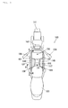
- Fig. 1 is a side view of a motorcycle according to an embodiment of "a motorcycle” of the invention, showing a state in which an airbag apparatus is mounted to the motorcycle.
- Fig. 2 is a diagram showing the motorcycle in Fig. 1 as viewed from the top.
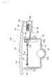
- Fig. 3 is a sectional view of the motorcycle in Fig. 2 taken along line A-A.
- Fig. 4 is a fragmentary enlarged view of Fig. 3.
- Fig. 5 is a cross sectional view of the motorcycle taken along line B-B in Fig. 2.
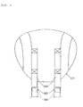
- Fig. 6 shows the structure of folded portions of webbings of the embodiment.
- Fig. 7 shows a module cover and a retainer of the embodiment viewed from the top of the vehicle.
- Fig. 8 shows the module cover and the retainer from the rear of the vehicle.
- Fig. 9 shows the module cover and the retainer from the side of the vehicle.
- Fig. 10 shows a section taken along line C-C in Fig. 7.
- Fig. 11 shows a section taken along line D-D in Fig. 7.
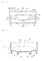
- Fig. 12 shows the retainer of the embodiment viewed from the top of the vehicle.
- Fig. 13 shows a section taken along line E-E in Fig. 12.
- Fig. 14 is an enlarged view of part F in Fig. 13.
- Fig. 15 shows the state of an airbag of the airbag apparatus at the start of inflation.
- Fig. 16 shows the airbag at the middle of inflation.
- Fig. 17 shows the airbag at the completion of inflation, as viewed from the side of the vehicle.
- Fig. 18 shows the airbag at the completion of inflation, as viewed from the top of the vehicle.
- Fig. 19 is a fragmentary sectional view of a module cover according to another embodiment.
- Fig. 1 is a side view of the motorcycle 100 according to an embodiment of the invention, showing a state in which an airbag apparatus 120 is mounted to the motorcycle 100.
- Fig. 2 shows the motorcycle 100 of Fig. 1, viewed from the top of the vehicle.
- the motorcycle 100 of the embodiment is an example of "a motorcycle” or "a motorcycle vehicle” of the invention.
- the motorcycle 100 is what is called a touring motorcycle and mainly comprises a body frame 101 including an engine and a main frame; a seat 103 that occupants can straddle; handlebars 104; a front wheel 111; and a rear wheel 112.
- a region above the body frame 101 of the motorcycle 100 and in front of an occupant seated in the seat 103 is defined as an occupant restraining region 150 in the event of a frontal collision of the motorcycle 100.
- the "frontal collision” in the embodiment indicates that the motorcycle 100 collides with various front objects (e.g., a vehicle, a pedestrian, an obstacle, and a guardrail, not shown for convenience sake).
- the "occupant restraining region 150" of the embodiment corresponds to "an occupant restraining region” of the invention, which is defined as a space extending in the direction of the forward movement of an occupant seated in the seat 103 during a frontal collision, for restraining the occupant who is flung ahead of the motorcycle by a kinetic energy.
- a front portion 102 of the body frame 101 includes a headlight, various meters, switches, a windshield, and the like.
- a fuel tank 106 is disposed at the front of a body component 105 between the front portion 102 and the seat 103.
- the airbag apparatus (also referred to as an airbag module) 120 is disposed in front of the fuel tank 106.
- Webbing covers 107 for covering a pair of right and left webbings 140 that is a component of the airbag apparatus 120 are disposed on both sides of the fuel tank 106.
- the webbings 140 cannot or can hardly be seen from the exterior owing to the covering by the webbing covers 107 in a normal state in which the airbag apparatus 120 is inoperative.
- the webbings 140 will be specifically described later in the description of the airbag apparatus 120.
- the structure of the airbag apparatus 120 of this embodiment will be specifically described with reference to Figs. 3 to 14.
- the airbag apparatus 120 is disposed so as to face the occupant restraining region 150 for the occupant seated in the seat 103.
- the airbag apparatus 120 corresponds to "an airbag apparatus" of the invention.
- Fig. 3 is a sectional view of the motorcycle 100 in Fig. 2 taken along line A-A;
- Fig. 4 is a fragmentary enlarged view of Fig. 3;
- Fig. 5 is a cross sectional view of the motorcycle 100 taken along line B-B in Fig. 2.
- the airbag apparatus 120 mainly comprises an airbag 121, an inflator 122, a retainer 123, a module cover 130, and the webbings 140.
- the airbag 121 is housed in the retainer 123 in a predetermined folded state (like a bellows or a roll) as shown in Figs. 3 and 4.
- a predetermined folded state like a bellows or a roll
- Figs. 3 and 4 the direction of the inflation (deployment) of the airbag 121 is indicated by arrow 10.
- the airbag 121 is made of a material similar to airbag cloth for cars.
- the airbag 121 corresponds to "an airbag" of the invention.
- the inflator 122 is a gas supply device that generates inflation gas and supplies it into the airbag 121 at a vehicle collision so that the airbag 121 in a folded state inflates while deploying from the retainer 123.
- the inflator 122 corresponds to "gas generation means" of the invention.
- the retainer 123 is shaped like a bottomed box having at least an airbag housing 123a for the airbag 121 and an inflator housing (recess) 123b for the inflator 122.
- the retainer 123 houses the airbag 121 and has an opening ("airbag opening" of the invention) at the top, which allows the deployment of the airbag 121.
- the retainer 123 is typically formed by pressing a metallic material.
- the retainer 123 corresponds to "a housing”.
- the webbings 140 extend from the interior of the retainer 123 to the exterior. Accordingly, the webbings 140 may be locally worn down by contact with the retainer 123 when the vehicle vibrates during traveling, when the webbings 140 are retracted from the housing for maintenance, and when the webbings 140 are extended from a loose state with the deployment of the airbag 121.
- a retainer wall 123c of the retainer 123 of the embodiment therefore has a bent portion 124 at the portion with which the webbing 140 may come into contact.
- the bent portion 124 has a smooth surface (a smooth surface 124a in Fig. 4) at the upper end of the metal-plate retainer 123.
- the smooth surface 124a is formed by folding back (bending) the upper end (plate end) of the retainer 123.
- the smooth surface 124a is an arc-shaped smooth surface (arcuate surface) corresponding to part of a circle or ellipse and as such, and it has a function of reducing the sliding resistance between the contact portion of the retainer 123 and the webbings 140 to enable smooth sliding.
- the smooth surface 124a is shaped to allow the movement of the webbings 140 while maintaining surface contact with the webbings 140 in the moving direction of the webbings 140 when the vehicle vibrates, when the webbings 140 are retracted for maintenance, and when the webbings 140 are moved with the deployment of the airbag 121.
- the curvatures of the webbings 140 and the smooth surface 124a are substantially equal at the region where the webbings 140 and the smooth surface 124a are in contact.
- the smooth surface 124a serves as means for guiding the webbings 140 relative to the retainer 123 while maintaining the surface contact so as to make the curvature of the webbings 140 agree with the curvature of the smooth surface 124a.
- This arrangement can prevent the wear of the webbings 140 made of, e.g., fibers due to contact with the metallic retainer 123 by means of the smooth surface 124a of the bent portion 124. Since, in this embodiment, the retainer 123 itself in contact with the webbings 140 has the smooth surface 124a, the smoothing structure is simplified, thus decreasing the number of components. It is preferable to increase the surface area of the smooth surface 124a of the bent portion 124 to thereby disperse the local frictional force to the webbings 140. A more detailed description of the retainer 123 will be given hereinafter.
- the module cover 130 covers the opening (airbag opening) of the retainer 123 from above to thereby cover the housed airbag 121, and has at least a top plate 131 and an erect portion 132, as shown in Figs. 3 and 4.
- the module cover 130 is typically molded of a resin material.
- the module cover 130 corresponds to "an airbag cover" of the invention.
- the top plate 131 of the module cover 130 extends substantially horizontally in the direction of the opening surface at the airbag opening region of the retainer 123 to thereby form the upper surface of the airbag apparatus 120.
- the erect portion 132 of the module cover 130 is a plate portion and extends vertically from the lower surface (back) of the top plate 131 along the retainer wall 123c (hooked portion) of the retainer 123 to cross the extending direction of the top plate 131.
- the erect portion 132 is secured to the retainer wall 123c with fixtures 128, to be described later, to thereby join the module cover 130 and the retainer 123 together.
- the top plate 131 corresponds to "a top plate”
- the erect portion 132 corresponds to "an erect portion" of the invention.
- a pair of right and left webbing through holes 134 that communicate the interior of the module cover 130 with the exterior is provided at the part of the rising portion 132 adjacent to the rear of the vehicle (adjacent to the occupant).
- the webbings 140 can extend from the interior to the exterior of the module cover 130 through the webbing through holes 134.
- the module cover 130 is torn open along a tear line 133 and two tear lines 135, to be described later, of the erect portion 132, to release the covering of the opening (airbag opening) of the retainer 123. This enables the deployment of the airbag 121.
- a more detailed description of the module cover 130 will be given hereinafter.
- the airbag 121 is tethered to the body of the motorcycle 100 with the pair of right and left elongated webbings 140.
- the webbings 140 are formed like a belt made of the same material as that of car seatbelts (resin fiber belt) or the same material as that of airbag cloth.
- the webbings 140 may be formed like a strap instead of the belt.
- a first end 141 of each webbing 140 is stitched to the airbag 121 and a second end 142 is joined to a fastener (a fastener 108 in Figs. 1 and 2) on the body.
- the webbings 140 extend in the front and back direction in parallel at two positions between the airbag apparatus 120 and the vehicle body. As shown in Figs.
- the webbings 140 when the airbag apparatus 120 is in an inoperative state, the webbings 140 extend in the housing space between the webbing covers 107 and the body component 105, and the upper parts of the webbings 140 are covered with the webbing covers 107.
- the webbings 140 correspond to "tethers" of the invention.
- each webbing 140 has a folded portion 143 below the webbing cover 107 so as to keep the looseness of the webbing 140 in a predetermined bunched state before the activation of the airbag apparatus 120 (while the airbag 121 is housed).
- the loose portions at the folded portions 143 of the webbings 140 are piled (folded back).
- the opposing surfaces of the loose portion are provided with a hook-and-loop fastener 144 that can temporarily hold the loose portion in the folded state (the predetermined bunched state).
- the hook-and-loop fastener 144 has a known structure, which is a detachable tape using a pile structure and is the so-called Velcro fastener. Specifically, the hook-and-loop fastener 144 has small mushroom-shaped expanded portions (or hooks) on one surface, and loops on the other surface. When the two surfaces are put together, the mushroom portions (or hooks) are caught (hooked) in the loops, so that they easily stick to each other; when they are pulled from each other, the mushrooms come out from the loops, so that they are easily peeled from each other.
- the folded (bunched) state of the folded portion 143 while the airbag is housed can temporarily be kept by the hook-and-loop fastener 144.
- the retaining force by the hook-and-loop fastener 144 is released, so that the folded (bunched) state of the folded portion 143 is released.
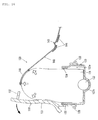
- Fig. 6 shows the structure of the folded portions 143 of the webbings 140 of the embodiment.
- the folded portions 143 are disposed substantially symmetrically. This arrangement can reduce the looseness of the webbings 140 while the airbag is housed and makes the loads of the right and left webbings 140, which extend upon the deployment of the airbag 121, on the airbag 121 substantially equal, thus being effective in deploying the airbag 121 laterally equally.
- the embodiment can employ another webbing holding means other than the hook-and-loop fastener 144, provided that the folded state of the folded portions 143 can temporarily be held.
- the folded state of the folded portions may be temporarily kept by a structure in which the folded portions are stitched up with a tear seam or a structure in which the folded portions are wound by an adhesive tape or the like.
- an appropriate structure can be adopted for temporarily holding the loose portions of the webbings 140 in a predetermined folded state (a predetermined folded-back state) or in a predetermined wound state with webbing holding means.
- Fig. 7 shows the module cover 130 and the retainer 123 of the embodiment viewed from the top of the vehicle; Fig. 8 shows them from the rear of the vehicle; Fig. 9 shows them from the side of the vehicle; Fig. 10 shows a section taken along line C-C of Fig. 7; and Fig. 11 shows a section taken along line D-D of Fig. 7.
- the erect portion 132 of the module cover 130 of the embodiment has a tear line 133 along the outer periphery thereof adjacent to the rear of the vehicle (adjacent to the occupant), and two tear lines 135 along the inner periphery on both sides.
- the tear lines 133 and 135 are provided not to the top plate 131 but to the erect portion 132 which is situated apart from the top plate 131. Accordingly, even if a load such as an occupant or a burden is applied from above the module cover 130, the load is not directly applied to the tear lines 133 and 135, thus preventing the module cover 130 from being torn open along the tear lines 133 and 135.
- the embodiment may have a continuous tear line from the erect portion 132 of the module cover 130 across another portion of the top plate 131.
- the disposition of the through holes 134 on the tear line 133 streamlines the structure because the installation locations are shared.
- the webbing through holes 134 are disposed on the tear line 133 of the erect portion 132, thereby streamlining the structure by sharing the installation location.
- the webbing through holes 134 serve as the tether through hole of the erect portion 132 so as to enable the webbings 140 to extend from the interior of the retainer 123 through the upper part of the retainer wall 123c (bent portion 124) to the outside of the module cover 130 (refer to Figs. 4, 7, and 8).
- the webbing through holes 134 correspond to "through portions" and "tether through holes" of the invention.
- the embodiment is characterized in the relative position between the webbing through holes 134 and the retainer wall 123c of the retainer 123. Specifically, the upper end of the retainer wall 123c of the retainer 123 is formed like steps above the webbing through holes 134 of the module cover 130 (more specifically, refer to Fig. 4).
- the retainer wall 123c interrupts the passage of water flowing from the exterior of the module cover 130 through the webbing through holes 134 into the retainer 123, and serves as "passage interrupting means that interrupts the passage of liquid flowing from the outside of the airbag through the through portion into the housing" of the invention.
- This arrangement enables interruption of the passage of liquid such as water flowing from the exterior of the module cover 130 into the webbing through holes 134 to prevent the liquid from flowing into the retainer 123 by the retainer wall 123c.
- the retainer 123 itself has a dam mechanism. This prevents water influx from the exterior of the module cover 130 into the retainer 123.
- the tear lines 133 and 135 are formed by providing triangular cutouts in the erect portion 132.
- three continuous grooves with a predetermined depth, or thin portions of a substantially even thickness within the thickness of the erect portion 132 are formed in the erect portion 132 adjacent to the rear and both sides of the vehicle.
- the tear lines 133 and 135. are also referred to as "linear grooves", “thin portions”, or “fragile portions” having a linear groove of a predetermined depth.
- the module cover 130 can be smoothly torn open along the tear lines 133 and 135 of the erect portion 132 by the deploying force of the airbag 121 in the event of a vehicle accident, so that the portion of the module cover 130 above the tear lines 133 and 135 deploys toward the front of the vehicle with the portion of the erect portion 132 adjacent to the front of the vehicle as the hinge.
- the portion of the cover lower than the tear lines 133 and 135 is secured to the retainer 123 when the tear lines 133 and 135 are torn open or the airbag 121 deploys such that fasteners 128 on the retainer 123 are hooked in the through holes of the erect portion 132 or fixed with rivets (refer to Fig. 8).
- the tear lines may be continuous grooves of a specified depth disposed at regular intervals, continuous perforations, or continuous slits disposed at regular intervals, instead of the continuous groove of a predetermined depth.
- the cutoffs of the tear lines 133 and 135 of the embodiment may be formed in dies during the molding of the module cover, or alternatively, may be formed by post machining such as laser beam machining or ultrasonic machining after the molding of the module cover.
- the sections of the tear lines 133 and 135 may be varied to a triangle, a semicircle, etc. as appropriate.
- the tear line 133 may be formed along the inner circumference of the erect portion 132 adjacent to the rear of the vehicle (adjacent to the occupant), while the tear lines 135 may be formed along the outer circumference of the both sides of the erect portion 132.
- FIG. 12 shows the retainer 123 of the embodiment viewed from the top of the vehicle;
- Fig. 13 shows a section taken along line E-E of Fig. 12;
- Fig. 14 shows an enlarged view of part F in Fig. 13.
- the retainer 123 of the embodiment has a pair of hole-like first through portions 125 at an inflator housing 123b at the bottom of the retainer 123, a pair of slit-like second through portions 126 at the right and left ends, and a pair of slit-like third through portions 127 at the front and rear ends.
- the first through portions 125, the second through portions 126, and the third through portions 127 extend vertically through the bottom of the retainer 123, and have a function of draining water entering the retainer 123 to the outside of the retainer 123.
- the water entering the retainer 123 is continuously or intermittently drained through the first through portions 125, the second through portions 126, and the third through portions 127 to the outside of the retainer 123 by gravitation.
- the housing like the retainer 123 of the embodiment is a bottomed box having an airbag opening on the top, liquid such as water or oil may be prone to enter or reside in the housing through the periphery of the airbag opening even with high tightness.
- liquid such as water or oil
- the embodiment has the first through portions 125, the second through portions 126, and the third through portions 127 for drainage at the bottom of the retainer 123.
- liquids such as oil entering the retainer 123 other than water may also be drained from the retainer 123 through the first through portions 125, the second through portions 126, and the third through portions 127.
- the through portion for drainage may be holes, slits, mesh, a punching plate, or other openings.
- the installation locations and the number of installation locations of the draining through portion may be varied as appropriate.
- the first through portions 125 are located at the recessed inflator housing 123b, which is the lowest of the bottom of the retainer 123. More specifically, the bottom of the retainer 123 has a downward slope (curved slope) toward the first through portions 125. Accordingly, the water entering the retainer 123 is collected to the first through portions 125 along the slope of the inflator housing 123b, and is surely drained through the first through portions 125 to the outside of the retainer 123.
- the second through portions 126 have the function of draining the water, which enters the retainer 123 and resides at the right and left ends thereof to the outside of the retainer 123 when the motorcycle 100 is parked at an angle using a side stand, or when the vehicle body tilts laterally during driving. Furthermore, as shown in Fig. 14, the bottom of the retainer 123 decreases in height toward the second through portions 126 (at an inclination angle ⁇ ). In other words, the bottom of the retainer 123 has a downward slope (linear slope) toward the second through portions 126.
- the water entering the retainer 123 is collected to the second through portions 126 along the slope of the bottom of the retainer 123 when the vehicle body tilts and even when the vehicle body is in a horizontal position, and is surely drained through the second through portions 126 to the outside of the retainer 123.
- the second through portions 126 are disposed at the right and left ends of the retainer 123, the second through portions 126 easily become the lowest of the bottom of the retainer 123 when the motorcycle tilt to the right or left side, thus increasing the draining function.
- the inclination angle ⁇ of the bottom of the retainer 123 may be appropriately set according to the specifications of the retainer 123.
- the third through portions 127 have the function of draining the water intruding into the retainer 123 and residing at the front and rear end.
- the motorcycle 100 tilts on an upward slope or downward slope run because the front of the body becomes higher or lower than the rear.
- the third through portion 127 on the front or rear side easily becomes the lowest of the bottom of the retainer 123, so that the water in the retainer 123 is surely drained from the retainer 123 through the third through portion 127.
- the first through portions 125 have a hole diameter of 7 mm or more (38 mm 2 or more in section area), and the second through portions 126 and the third through portions 127 have the same section area as that of the first through portions 125 or the same slit width as the hole diameter of the first through portions 125.
- FIG. 15 shows the state of the airbag 121 of the airbag apparatus 120 at the start of inflation
- Fig. 16 shows the airbag 121 at the middle of inflation
- Figs. 17 and 18 show the airbag 121 at the completion of inflation.
- Fig. 17 shows the airbag 121 at the completion of inflation, viewed from the side of the vehicle
- Fig. 18 shows the airbag 121 at the completion of inflation, viewed from the top of the vehicle.
- the inflator 122 of the airbag apparatus 120 is activated to supply inflation gas generated by the inflator 122 into the airbag 121. This starts the inflation (deployment) of the airbag 121 in the direction of arrow 10 in the airbag apparatus 120 of Fig. 3 in a state before activation. Since inflation gas is continuously fed into the airbag 121, the airbag 121 is expanded in sequence from the retainer 123.
- the airbag 121 pushes the top plate 131 of the module cover 130 from below in the retainer 123 in the process of deployment.
- the module cover 130 that has received a predetermined deploying force or more from the airbag 121 is torn open along the tear lines (the tear lines 133 and 135) of the erect portion 132.
- the webbings 140 stitched to the airbag 121 are subjected to a tensile load via the first end 141.
- the webbings 140 push open the webbing covers 107 upward to thereby release the covering by the webbing covers 107.
- the module cover 130 torn open along the tear lines further receives the deploying force from the airbag 121 to deploy ahead of the vehicle with the portion of the erect portion 132 adjacent to the front of the vehicle as the hinge.
- the retaining force by the hook-and-loop fastener 144 is canceled, so that the folded state of the folded portions 143 is released.
- the loads on the airbag 121 by the webbings 140 extending during the deployment of the airbag 121 can be made substantially equal on the right and left, whereby the airbag 121 can deploy bilaterally evenly.
- the airbag 121 is completely deployed.
- the inflated airbag 121 fills the occupant restraining region 150 in front of a rider R in Fig. 17.
- the rider R who is moving forward by the kinetic energy of the collision is restrained by the airbag 121 and the impact to the rider R during restraint is reduced.
- the webbings 140 fully extend substantially linearly between the airbag 121 and the fastener 108 to restrict the motion of the airbag 121 moving upward and forward of the vehicle by the tension thereof.
- the fully inflated airbag 121 comes into contact with the front portion 102 at the front of the vehicle, and into contact with the handlebars 104 at both sides. This arrangement stabilizes the restraint of the rider R with the fully inflated airbag 121.
- the upper end of the retainer wall 123c of the retainer 123 is located above the webbing through holes 134 of the module cover 130 and formed like steps, thereby preventing liquid such as water, which flows from the exterior into the webbing through holes 134, from flowing into the retainer 123 with the retainer wall 123c.
- the embodiment can provide a simple passage interrupting structure because the retainer 123 itself has the passage interrupting structure owing to the difference in height between the upper end of the retainer wall 123c and the webbing through holes 134.
- the function of reducing the slide resistance between the retainer 123 and the webbings 140, like the bent portion 124, is particularly effective.
- the influx of liquid such as water into the retainer 123 is prevented by the passage interrupting structure (dam structure) in which the retainer wall 123c of the retainer 123 is disposed above the webbing through holes 134.
- the invention may have the passage interrupting structure at the module cover 130 or between the retainer 123 and the module cover 130.
- the invention may dispose the passage interrupting wall in a desired position in the passage from the exterior of the module cover 130 through the webbing through holes 134 into the retainer 123.
- the passage interrupting structure may be achieved by another structure as shown in Fig. 19.
- Fig. 19 is a fragmentary sectional view of a module cover 230 according to another embodiment.
- the module cover 230 shown in Fig. 19 has an interrupting member 236 mounted to the outer circumference of the erect portion 132 with a mounting portion 236b.
- the interrupting member 236 has a wall 236a extending from above the webbing through hole 134 downward along the extension of the erect portion 132.
- the wall 236a covers the webbing through hole 134 from the outside while allowing the webbing 140 to pass through the webbing through hole 134.
- the interrupting member 236 is made of resin as are the top plate 131 and the erect portion 132, and is fixed to the erect portion 132 with a bolt or a rivet.
- the interrupting member 236 interrupts the passage of water flowing from the outside of the module cover 230 into the webbing through hole 134, and serves as the "passage interrupting means" of the invention. This arrangement enables the influx of liquid such as water from the exterior of the module cover 230 into the webbing through hole 134 to be interrupted by using the interrupting member 236.
- an interrupting member similar to the interrupting member 236 of Fig. 19 may be disposed on the inner circumference of the erect portion 132 in place of the outer circumference.
- the embodiment has a structure of interrupting the passage of water flowing through the webbing through holes 134 of the module-cover erect portion 132
- the invention may be applied to a passage interrupting structure of various types of through portions at the module-cover erect portion 132.
- the invention may be applied to other types of motorcycle such as motor scooters having a space that enables lateral movement of the rider's legs between the handlebars and the seat and to motorcycle vehicles other than the motorcycle 100.
- the position of the airbag apparatus 120 may be varied as appropriate, provided that the airbag 121 can deploy into a desired region in a vehicle collision.
- the airbag apparatus 120 may be disposed behind or lower than that shown in Fig. 1.
Landscapes
- Engineering & Computer Science (AREA)
- Mechanical Engineering (AREA)
- Air Bags (AREA)
Abstract
Description
- The present invention relates to an airbag apparatus to be mounted to a motorcycle.
- There have been various known techniques of restraining occupants of motorcycles with airbag apparatuses. For example, known techniques include a technique of restraining an occupant with an airbag inflated by inflation gas in a frontal collision (e.g., refer to
Japanese Unexamined Patent Application Publication No. 2003-327182 Japanese Unexamined Patent Application Publication No. 2003-327182 - In the airbag apparatus described in
Japanese Unexamined Patent Application Publication No. 2003-327182 - The invention is made in view of the above problems. Accordingly, it is an object of the invention to provide an improved airbag apparatus, in particular a technique effective in preventing liquid from flowing from the exterior of the airbag cover into the housing of an airbag apparatus for a motor cycle in which an airbag opening of a housing to store an airbag is covered by an airbag cover.
- According to the present invention, this object is achieved by an airbag apparatus as defined in
Claim 1 and a motorcycle as defined in Claim 7. The dependent claims define preferred or advantageous embodiments. - Typically, the invention can be applied in constructing airbag apparatuses to be mounted to various motorcycles. In this specification, "a motorcycle", a typical example of vehicles, includes various saddle-type vehicles that an occupant straddles, such as touring motorcycles having a fuel tank in front of an occupant seat and motor scooters having a space between an occupant seat and a handlebar-supporting head pipe. In addition to the motorcycles, the "motorcycle" includes vehicles that occupants straddle and having three or more running wheels (e.g., three-wheel motorbikes for use in home delivery service and three- or four-wheel buggies for bad roads) and vehicles that occupants ride on and running by sledges or caterpillars, such as snow mobiles.
- According to an aspect of the present invention, an airbag apparatus to be mounted to a motorcycle includes at least a gas generation means, an airbag, a housing, an airbag cover, a through portion, and a passage interrupting means.
- The gas generation means is a means for generating airbag inflation gas. The airbag restrains an occupant by deploying into an occupant restraining region in front of the occupant by the airbag inflation gas generated by the gas generation means in a frontal collision of the motorcycle. Here the "frontal collision" generally indicates that the motorcycle collides with a running or still front object such as a vehicle, a pedestrian, an obstacle or the like. The "occupant restraining region" is defined as a space extending in the direction of the forward movement of an occupant who is moving ahead of the motorcycle by a kinetic energy during a frontal collision, for restraining the occupant who is flung ahead of the motorcycle by the kinetic energy.
- The housing houses at least an airbag and has an airbag opening that allows the deployment of the airbag. The housing is typically a bottomed-box-shaped retainer. The airbag cover of the invention covers an airbag housed in the housing.
- The airbag cover has at least a top plate and an erect portion. The top plate extends to the opening surface of the airbag opening region of the housing. The erect portion extends from the lower surface (back) of the top plate of the airbag cover along the extension of the housing wall. The airbag cover is mounted to the outer circumference of the housing wall with the erect portion. Specifically, the airbag cover may be directly mounted to the outer circumference of the housing wall with the erect portion, or alternatively, may be indirectly mounted via another member. The erect portion mounted to the outer circumference of the housing wall is fixed with fixing means such as a bolt or rivet and as such, the airbag cover is mounted to the housing.
- The through portion is provided to the erect portion of the airbag cover. The through portion may include various holes, openings, cutoffs, grooves, and gaps that allow predetermined members to pass through or for use in mounting the airbag cover to the housing. In a conventional apparatus, this structure has the problem that liquid such as water or oil may enter the housing from the exterior through the through portion. Particularly, general motorcycles have an airbag apparatus exposed to the outside of the body in contrast to cars, so that this problem may be pronounced under the influence of rain, cleaning water, and humidity.
- Accordingly, the invention adopts a structure in which the airbag apparatus has passage interrupting means. The passage interrupting means interrupts the passage of liquid flowing from the outside of the airbag cover through the through portion into the housing. The passage interrupting means may be a passage interrupting wall (dam) on the cover outer or inner circumference around the through portion of the erect portion, a passage interrupting wall on the housing outer circumference around the through portion of the erect portion, or a passage interrupting step in which the upper end of the housing wall is located higher than the through portion. The passage interrupting wall can be disposed at a desired portion in a passage from the exterior of the airbag cover through the through portion to the interior of the housing.
- The above arrangement of the airbag apparatus can prevent liquid from flowing from the exterior of the airbag cover into the housing with the passage interrupting means.
- The passage interrupting means may adopt a structure in which the upper end of the housing wall is located above the through portion. The through portion of the airbag cover may be disposed lower than the upper end of the housing wall. With this structure, the upper part of the housing wall and the through portion are disposed like steps, so that liquid such as water flowing into the through portion can be prevented from flowing into the housing by the housing wall serving as the passage interrupting means. The structure may use the housing wall itself, or alternatively, may use another member mounted to the upper part of the housing wall.
- With this arrangement, the use of the structure of the housing as passage interrupting means simplifies the structure of the passage interrupting means.
- The airbag apparatus may further include a tether and a through hole.
- The tether is an elongated member that tethers the airbag in the housing to the vehicle body. The tether may be an elongated member having a strength sufficient to retain the airbag to the vehicle body. The "elongated member" of the invention may broadly include a belt and a strap, typically a belt-like webbing made of resin fibers or the like. The tether with such a structure has the function of restricting the forward movement of the airbag by retaining the airbag to the vehicle body by the tension upon completion of deployment of the airbag. The number of tethers may be varied to one or more, as necessary. The tether through hole serves as a tether through portion at the erect portion so as to enable the tether to extend from the housing through the upper part of the housing wall to the outside of the airbag cover. The tether through hole is an opening according to the size of the tether, thus needing some sectional area. The tether through hole may have the possibility of water influx. For the structure, the passage interrupting means is particularly effective in interrupting the passage of water flowing into the housing through the tether through hole.
- Particularly in the airbag apparatus having an elongated tether for tethering the airbag to the vehicle body, liquid can be prevented from flowing from the exterior of the airbag cover into the housing through the tether through hole of the erect portion of the airbag cover.
- According to another aspect of the present invention, a motorcycle with an airbag apparatus is provided. The motorcycle with an airbag apparatus has the airbag apparatus according to any one aspect or embodiment of the invention.
- Thus, a motorcycle is provided having an airbag apparatus capable of preventing the inflow of the liquid from the exterior of the airbag cover into the housing.
- In the airbag apparatus for motorcycles with a structure in which the airbag opening of an airbag housing is covered with an airbag cover, the liquid can be prevented from flowing from the exterior of the airbag cover through the through portion into the housing using the passage interrupting means.
- An embodiment of the present invention will be described specifically with reference to the drawings.
- Fig. 1 is a side view of a motorcycle according to an embodiment of "a motorcycle" of the invention, showing a state in which an airbag apparatus is mounted to the motorcycle.
- Fig. 2 is a diagram showing the motorcycle in Fig. 1 as viewed from the top.
- Fig. 3 is a sectional view of the motorcycle in Fig. 2 taken along line A-A.
- Fig. 4 is a fragmentary enlarged view of Fig. 3.
- Fig. 5 is a cross sectional view of the motorcycle taken along line B-B in Fig. 2.
- Fig. 6 shows the structure of folded portions of webbings of the embodiment.
- Fig. 7 shows a module cover and a retainer of the embodiment viewed from the top of the vehicle.
- Fig. 8 shows the module cover and the retainer from the rear of the vehicle.
- Fig. 9 shows the module cover and the retainer from the side of the vehicle.
- Fig. 10 shows a section taken along line C-C in Fig. 7.
- Fig. 11 shows a section taken along line D-D in Fig. 7.
- Fig. 12 shows the retainer of the embodiment viewed from the top of the vehicle.
- Fig. 13 shows a section taken along line E-E in Fig. 12.
- Fig. 14 is an enlarged view of part F in Fig. 13.
- Fig. 15 shows the state of an airbag of the airbag apparatus at the start of inflation.
- Fig. 16 shows the airbag at the middle of inflation.
- Fig. 17 shows the airbag at the completion of inflation, as viewed from the side of the vehicle.
- Fig. 18 shows the airbag at the completion of inflation, as viewed from the top of the vehicle.
- Fig. 19 is a fragmentary sectional view of a module cover according to another embodiment.
- Referring first to Figs. 1 and 2, the entire structure of a
motorcycle 100 will be described. Fig. 1 is a side view of themotorcycle 100 according to an embodiment of the invention, showing a state in which anairbag apparatus 120 is mounted to themotorcycle 100. Fig. 2 shows themotorcycle 100 of Fig. 1, viewed from the top of the vehicle. Themotorcycle 100 of the embodiment is an example of "a motorcycle" or "a motorcycle vehicle" of the invention. - Referring to Figs. 1 and 2, the
motorcycle 100 is what is called a touring motorcycle and mainly comprises abody frame 101 including an engine and a main frame; aseat 103 that occupants can straddle;handlebars 104; afront wheel 111; and arear wheel 112. - A region above the
body frame 101 of themotorcycle 100 and in front of an occupant seated in theseat 103 is defined as anoccupant restraining region 150 in the event of a frontal collision of themotorcycle 100. The "frontal collision" in the embodiment indicates that themotorcycle 100 collides with various front objects (e.g., a vehicle, a pedestrian, an obstacle, and a guardrail, not shown for convenience sake). The "occupant restraining region 150" of the embodiment corresponds to "an occupant restraining region" of the invention, which is defined as a space extending in the direction of the forward movement of an occupant seated in theseat 103 during a frontal collision, for restraining the occupant who is flung ahead of the motorcycle by a kinetic energy. - A
front portion 102 of thebody frame 101 includes a headlight, various meters, switches, a windshield, and the like. Afuel tank 106 is disposed at the front of abody component 105 between thefront portion 102 and theseat 103. The airbag apparatus (also referred to as an airbag module) 120 is disposed in front of thefuel tank 106. Webbing covers 107 for covering a pair of right and leftwebbings 140 that is a component of theairbag apparatus 120 are disposed on both sides of thefuel tank 106. Thewebbings 140 cannot or can hardly be seen from the exterior owing to the covering by the webbing covers 107 in a normal state in which theairbag apparatus 120 is inoperative. Thewebbings 140 will be specifically described later in the description of theairbag apparatus 120. - The structure of the
airbag apparatus 120 of this embodiment will be specifically described with reference to Figs. 3 to 14. Theairbag apparatus 120 is disposed so as to face theoccupant restraining region 150 for the occupant seated in theseat 103. Theairbag apparatus 120 corresponds to "an airbag apparatus" of the invention. - Fig. 3 is a sectional view of the
motorcycle 100 in Fig. 2 taken along line A-A; Fig. 4 is a fragmentary enlarged view of Fig. 3; and Fig. 5 is a cross sectional view of themotorcycle 100 taken along line B-B in Fig. 2. As shown in Figs. 3 and 4, theairbag apparatus 120 mainly comprises anairbag 121, aninflator 122, aretainer 123, amodule cover 130, and thewebbings 140. - The
airbag 121 is housed in theretainer 123 in a predetermined folded state (like a bellows or a roll) as shown in Figs. 3 and 4. In Fig. 3, the direction of the inflation (deployment) of theairbag 121 is indicated by arrow 10. Theairbag 121 is made of a material similar to airbag cloth for cars. Theairbag 121 corresponds to "an airbag" of the invention. - The
inflator 122 is a gas supply device that generates inflation gas and supplies it into theairbag 121 at a vehicle collision so that theairbag 121 in a folded state inflates while deploying from theretainer 123. Theinflator 122 corresponds to "gas generation means" of the invention. - The
retainer 123 is shaped like a bottomed box having at least anairbag housing 123a for theairbag 121 and an inflator housing (recess) 123b for theinflator 122. Theretainer 123 houses theairbag 121 and has an opening ("airbag opening" of the invention) at the top, which allows the deployment of theairbag 121. Theretainer 123 is typically formed by pressing a metallic material. Theretainer 123 corresponds to "a housing". - In this embodiment, the
webbings 140, to be described later, extend from the interior of theretainer 123 to the exterior. Accordingly, thewebbings 140 may be locally worn down by contact with theretainer 123 when the vehicle vibrates during traveling, when thewebbings 140 are retracted from the housing for maintenance, and when thewebbings 140 are extended from a loose state with the deployment of theairbag 121. Aretainer wall 123c of theretainer 123 of the embodiment therefore has abent portion 124 at the portion with which thewebbing 140 may come into contact. Thebent portion 124 has a smooth surface (asmooth surface 124a in Fig. 4) at the upper end of the metal-plate retainer 123. Thesmooth surface 124a is formed by folding back (bending) the upper end (plate end) of theretainer 123. Thesmooth surface 124a is an arc-shaped smooth surface (arcuate surface) corresponding to part of a circle or ellipse and as such, and it has a function of reducing the sliding resistance between the contact portion of theretainer 123 and thewebbings 140 to enable smooth sliding. - Specifically, the
smooth surface 124a is shaped to allow the movement of thewebbings 140 while maintaining surface contact with thewebbings 140 in the moving direction of thewebbings 140 when the vehicle vibrates, when thewebbings 140 are retracted for maintenance, and when thewebbings 140 are moved with the deployment of theairbag 121. At that time, the curvatures of thewebbings 140 and thesmooth surface 124a are substantially equal at the region where thewebbings 140 and thesmooth surface 124a are in contact. In other words, thesmooth surface 124a serves as means for guiding thewebbings 140 relative to theretainer 123 while maintaining the surface contact so as to make the curvature of thewebbings 140 agree with the curvature of thesmooth surface 124a. - This arrangement can prevent the wear of the
webbings 140 made of, e.g., fibers due to contact with themetallic retainer 123 by means of thesmooth surface 124a of thebent portion 124. Since, in this embodiment, theretainer 123 itself in contact with thewebbings 140 has thesmooth surface 124a, the smoothing structure is simplified, thus decreasing the number of components. It is preferable to increase the surface area of thesmooth surface 124a of thebent portion 124 to thereby disperse the local frictional force to thewebbings 140. A more detailed description of theretainer 123 will be given hereinafter. - The
module cover 130 covers the opening (airbag opening) of theretainer 123 from above to thereby cover the housedairbag 121, and has at least atop plate 131 and anerect portion 132, as shown in Figs. 3 and 4. Themodule cover 130 is typically molded of a resin material. Themodule cover 130 corresponds to "an airbag cover" of the invention. - The
top plate 131 of themodule cover 130 extends substantially horizontally in the direction of the opening surface at the airbag opening region of theretainer 123 to thereby form the upper surface of theairbag apparatus 120. Theerect portion 132 of themodule cover 130 is a plate portion and extends vertically from the lower surface (back) of thetop plate 131 along theretainer wall 123c (hooked portion) of theretainer 123 to cross the extending direction of thetop plate 131. Theerect portion 132 is secured to theretainer wall 123c withfixtures 128, to be described later, to thereby join themodule cover 130 and theretainer 123 together. Thetop plate 131 corresponds to "a top plate", and theerect portion 132 corresponds to "an erect portion" of the invention. - Referring to Fig. 4, a pair of right and left webbing through
holes 134 that communicate the interior of themodule cover 130 with the exterior is provided at the part of the risingportion 132 adjacent to the rear of the vehicle (adjacent to the occupant). Thewebbings 140, to be described later, can extend from the interior to the exterior of themodule cover 130 through the webbing throughholes 134. When thetop plate 131 receives the deploying force of theairbag 121 at a vehicle collision, themodule cover 130 is torn open along atear line 133 and twotear lines 135, to be described later, of theerect portion 132, to release the covering of the opening (airbag opening) of theretainer 123. This enables the deployment of theairbag 121. A more detailed description of themodule cover 130 will be given hereinafter. - In this embodiment, the
airbag 121 is tethered to the body of themotorcycle 100 with the pair of right and leftelongated webbings 140. Thewebbings 140 are formed like a belt made of the same material as that of car seatbelts (resin fiber belt) or the same material as that of airbag cloth. Thewebbings 140 may be formed like a strap instead of the belt. Afirst end 141 of eachwebbing 140 is stitched to theairbag 121 and asecond end 142 is joined to a fastener (afastener 108 in Figs. 1 and 2) on the body. In other words, thewebbings 140 extend in the front and back direction in parallel at two positions between theairbag apparatus 120 and the vehicle body. As shown in Figs. 4 and 5, when theairbag apparatus 120 is in an inoperative state, thewebbings 140 extend in the housing space between the webbing covers 107 and thebody component 105, and the upper parts of thewebbings 140 are covered with the webbing covers 107. Thewebbings 140 correspond to "tethers" of the invention. - Since the
webbings 140 are in an irregularly loose state while the airbag is housed, the extending motion of thewebbings 140 from the loose state with the deployment of the airbag at a frontal collision of the vehicle may exert an influence on a desired deploying motion of theairbag 121. Therefore, in the embodiment, eachwebbing 140 has a foldedportion 143 below thewebbing cover 107 so as to keep the looseness of thewebbing 140 in a predetermined bunched state before the activation of the airbag apparatus 120 (while theairbag 121 is housed). The loose portions at the foldedportions 143 of thewebbings 140 are piled (folded back). The opposing surfaces of the loose portion are provided with a hook-and-loop fastener 144 that can temporarily hold the loose portion in the folded state (the predetermined bunched state). - The hook-and-
loop fastener 144 has a known structure, which is a detachable tape using a pile structure and is the so-called Velcro fastener. Specifically, the hook-and-loop fastener 144 has small mushroom-shaped expanded portions (or hooks) on one surface, and loops on the other surface. When the two surfaces are put together, the mushroom portions (or hooks) are caught (hooked) in the loops, so that they easily stick to each other; when they are pulled from each other, the mushrooms come out from the loops, so that they are easily peeled from each other. - With such a structure, the folded (bunched) state of the folded
portion 143 while the airbag is housed can temporarily be kept by the hook-and-loop fastener 144. On the other hand, when a predetermined tensile load is applied to thewebbings 140 at the deployment of theairbag 121, the retaining force by the hook-and-loop fastener 144 is released, so that the folded (bunched) state of the foldedportion 143 is released. - Fig. 6 shows the structure of the folded
portions 143 of thewebbings 140 of the embodiment. As shown in Fig. 6, in this embodiment, the foldedportions 143 are disposed substantially symmetrically. This arrangement can reduce the looseness of thewebbings 140 while the airbag is housed and makes the loads of the right and leftwebbings 140, which extend upon the deployment of theairbag 121, on theairbag 121 substantially equal, thus being effective in deploying theairbag 121 laterally equally. - For the webbing holding structure, the embodiment can employ another webbing holding means other than the hook-and-
loop fastener 144, provided that the folded state of the foldedportions 143 can temporarily be held. For example, the folded state of the folded portions may be temporarily kept by a structure in which the folded portions are stitched up with a tear seam or a structure in which the folded portions are wound by an adhesive tape or the like. At that time, an appropriate structure can be adopted for temporarily holding the loose portions of thewebbings 140 in a predetermined folded state (a predetermined folded-back state) or in a predetermined wound state with webbing holding means. - Referring to Figs. 7 to 11, a more detailed description of the
module cover 130 will be given. Fig. 7 shows themodule cover 130 and theretainer 123 of the embodiment viewed from the top of the vehicle; Fig. 8 shows them from the rear of the vehicle; Fig. 9 shows them from the side of the vehicle; Fig. 10 shows a section taken along line C-C of Fig. 7; and Fig. 11 shows a section taken along line D-D of Fig. 7. - As shown in Figs. 7 to 9, the
erect portion 132 of themodule cover 130 of the embodiment has atear line 133 along the outer periphery thereof adjacent to the rear of the vehicle (adjacent to the occupant), and twotear lines 135 along the inner periphery on both sides. In this embodiment, thetear lines top plate 131 but to theerect portion 132 which is situated apart from thetop plate 131. Accordingly, even if a load such as an occupant or a burden is applied from above themodule cover 130, the load is not directly applied to thetear lines module cover 130 from being torn open along thetear lines erect portion 132 of themodule cover 130 across another portion of thetop plate 131. - The disposition of the through
holes 134 on thetear line 133 streamlines the structure because the installation locations are shared. - According to the embodiment, the webbing through
holes 134 are disposed on thetear line 133 of theerect portion 132, thereby streamlining the structure by sharing the installation location. The webbing throughholes 134 serve as the tether through hole of theerect portion 132 so as to enable thewebbings 140 to extend from the interior of theretainer 123 through the upper part of theretainer wall 123c (bent portion 124) to the outside of the module cover 130 (refer to Figs. 4, 7, and 8). The webbing throughholes 134 correspond to "through portions" and "tether through holes" of the invention. - With the structure of the
module cover 130 having the webbing throughholes 134 at theerect portion 132, liquid such as water may enter the housing through the webbing throughholes 134 from the exterior of themodule cover 130. Particularly, general motorcycles have an airbag apparatus exposed to the outside of the vehicle body in contrast to cars, so that this problem may be pronounced under the influence of rain, cleaning water, and humidity. Thus, the embodiment is characterized in the relative position between the webbing throughholes 134 and theretainer wall 123c of theretainer 123. Specifically, the upper end of theretainer wall 123c of theretainer 123 is formed like steps above the webbing throughholes 134 of the module cover 130 (more specifically, refer to Fig. 4). Theretainer wall 123c interrupts the passage of water flowing from the exterior of themodule cover 130 through the webbing throughholes 134 into theretainer 123, and serves as "passage interrupting means that interrupts the passage of liquid flowing from the outside of the airbag through the through portion into the housing" of the invention. This arrangement enables interruption of the passage of liquid such as water flowing from the exterior of themodule cover 130 into the webbing throughholes 134 to prevent the liquid from flowing into theretainer 123 by theretainer wall 123c. In short, in the embodiment, theretainer 123 itself has a dam mechanism. This prevents water influx from the exterior of themodule cover 130 into theretainer 123. - As shown in Figs. 10 and 11, the
tear lines erect portion 132. Thus three continuous grooves with a predetermined depth, or thin portions of a substantially even thickness within the thickness of theerect portion 132 are formed in theerect portion 132 adjacent to the rear and both sides of the vehicle. Thus thetear lines tear lines 133 and 135 (the thickness of the thin portions) is appropriately set on the basis of the specifications of theairbag 121, such as a deploying force, themodule cover 130 can be smoothly torn open along thetear lines erect portion 132 by the deploying force of theairbag 121 in the event of a vehicle accident, so that the portion of themodule cover 130 above thetear lines erect portion 132 adjacent to the front of the vehicle as the hinge. At that time, the portion of the cover lower than thetear lines retainer 123 when thetear lines airbag 121 deploys such thatfasteners 128 on theretainer 123 are hooked in the through holes of theerect portion 132 or fixed with rivets (refer to Fig. 8). The tear lines may be continuous grooves of a specified depth disposed at regular intervals, continuous perforations, or continuous slits disposed at regular intervals, instead of the continuous groove of a predetermined depth. - The cutoffs of the
tear lines tear lines tear line 133 may be formed along the inner circumference of theerect portion 132 adjacent to the rear of the vehicle (adjacent to the occupant), while thetear lines 135 may be formed along the outer circumference of the both sides of theerect portion 132. - Referring then to Figs. 12 to 14, a more detailed structure of the
retainer 123 will be presented. Fig. 12 shows theretainer 123 of the embodiment viewed from the top of the vehicle; Fig. 13 shows a section taken along line E-E of Fig. 12; Fig. 14 shows an enlarged view of part F in Fig. 13. - As shown in Figs. 12 and 13, the
retainer 123 of the embodiment has a pair of hole-like first throughportions 125 at aninflator housing 123b at the bottom of theretainer 123, a pair of slit-like second throughportions 126 at the right and left ends, and a pair of slit-like third throughportions 127 at the front and rear ends. The first throughportions 125, the second throughportions 126, and the third throughportions 127 extend vertically through the bottom of theretainer 123, and have a function of draining water entering theretainer 123 to the outside of theretainer 123. Thus, the water entering theretainer 123 is continuously or intermittently drained through the first throughportions 125, the second throughportions 126, and the third throughportions 127 to the outside of theretainer 123 by gravitation. - Since the housing like the
retainer 123 of the embodiment is a bottomed box having an airbag opening on the top, liquid such as water or oil may be prone to enter or reside in the housing through the periphery of the airbag opening even with high tightness. Particularly, general motorcycles have an airbag apparatus exposed to the outside of the vehicle body in contrast to cars, so that such a problem may be pronounced under the influence of rain, cleaning water, and humidity. Accordingly, the embodiment has the first throughportions 125, the second throughportions 126, and the third throughportions 127 for drainage at the bottom of theretainer 123. Of course, liquids such as oil entering theretainer 123 other than water may also be drained from theretainer 123 through the first throughportions 125, the second throughportions 126, and the third throughportions 127. The through portion for drainage may be holes, slits, mesh, a punching plate, or other openings. In this embodiment, the installation locations and the number of installation locations of the draining through portion may be varied as appropriate. - The first through
portions 125 are located at the recessedinflator housing 123b, which is the lowest of the bottom of theretainer 123. More specifically, the bottom of theretainer 123 has a downward slope (curved slope) toward the first throughportions 125. Accordingly, the water entering theretainer 123 is collected to the first throughportions 125 along the slope of theinflator housing 123b, and is surely drained through the first throughportions 125 to the outside of theretainer 123. - On the other hand, the second through
portions 126 have the function of draining the water, which enters theretainer 123 and resides at the right and left ends thereof to the outside of theretainer 123 when themotorcycle 100 is parked at an angle using a side stand, or when the vehicle body tilts laterally during driving. Furthermore, as shown in Fig. 14, the bottom of theretainer 123 decreases in height toward the second through portions 126 (at an inclination angle θ). In other words, the bottom of theretainer 123 has a downward slope (linear slope) toward the second throughportions 126. Thus, the water entering theretainer 123 is collected to the second throughportions 126 along the slope of the bottom of theretainer 123 when the vehicle body tilts and even when the vehicle body is in a horizontal position, and is surely drained through the second throughportions 126 to the outside of theretainer 123. Particularly, since the second throughportions 126 are disposed at the right and left ends of theretainer 123, the second throughportions 126 easily become the lowest of the bottom of theretainer 123 when the motorcycle tilt to the right or left side, thus increasing the draining function. Motorcycles tilt to the right or left when parked at a rightward or leftward inclination, or when tilted to the right or left during driving on a right or left curve. The inclination angle θ of the bottom of theretainer 123 may be appropriately set according to the specifications of theretainer 123. - Furthermore, the third through
portions 127 have the function of draining the water intruding into theretainer 123 and residing at the front and rear end. For example, themotorcycle 100 tilts on an upward slope or downward slope run because the front of the body becomes higher or lower than the rear. In this embodiment, the third throughportion 127 on the front or rear side easily becomes the lowest of the bottom of theretainer 123, so that the water in theretainer 123 is surely drained from theretainer 123 through the third throughportion 127. Vehicles tilt to the front or rear during running on an uphill or downhill slope or when theretainer 123 itself is combined to the body on a slant. - Preferably, for the draining structure of the embodiment in view of the surface tension of water, the first through
portions 125 have a hole diameter of 7 mm or more (38 mm2 or more in section area), and the second throughportions 126 and the third throughportions 127 have the same section area as that of the first throughportions 125 or the same slit width as the hole diameter of the first throughportions 125. - Referring now to Figs. 15 to 18, the motion of the
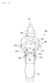
airbag apparatus 120 will be described. Fig. 15 shows the state of theairbag 121 of theairbag apparatus 120 at the start of inflation; Fig. 16 shows theairbag 121 at the middle of inflation; and Figs. 17 and 18 show theairbag 121 at the completion of inflation. Specifically, Fig. 17 shows theairbag 121 at the completion of inflation, viewed from the side of the vehicle; and Fig. 18 shows theairbag 121 at the completion of inflation, viewed from the top of the vehicle. - When the
motorcycle 100 comes into a collision in the traveling direction, the occupant is moving (flung) ahead of themotorcycle 100. In the embodiment, upon detection of the frontal collision, theinflator 122 of theairbag apparatus 120 is activated to supply inflation gas generated by the inflator 122 into theairbag 121. This starts the inflation (deployment) of theairbag 121 in the direction of arrow 10 in theairbag apparatus 120 of Fig. 3 in a state before activation. Since inflation gas is continuously fed into theairbag 121, theairbag 121 is expanded in sequence from theretainer 123. - As shown in Fig. 15, with the
airbag 121 at the beginning of deployment, theairbag 121 pushes thetop plate 131 of themodule cover 130 from below in theretainer 123 in the process of deployment. Thus themodule cover 130 that has received a predetermined deploying force or more from theairbag 121 is torn open along the tear lines (thetear lines 133 and 135) of theerect portion 132. Upon starting the deployment of theairbag 121, thewebbings 140 stitched to theairbag 121 are subjected to a tensile load via thefirst end 141. Thus thewebbings 140 push open the webbing covers 107 upward to thereby release the covering by the webbing covers 107. - As shown in Fig. 16, with the
airbag 121 in the middle of deployment, themodule cover 130 torn open along the tear lines further receives the deploying force from theairbag 121 to deploy ahead of the vehicle with the portion of theerect portion 132 adjacent to the front of the vehicle as the hinge. At that time, when a further tensile load is applied to thewebbings 140 via thefirst end 141, the retaining force by the hook-and-loop fastener 144 is canceled, so that the folded state of the foldedportions 143 is released. Since the foldedportions 143 of thewebbings 140 of the embodiment are generally disposed symmetrically, the loads on theairbag 121 by thewebbings 140 extending during the deployment of theairbag 121 can be made substantially equal on the right and left, whereby theairbag 121 can deploy bilaterally evenly. - Thus, as shown in Figs. 17 and 18, the
airbag 121 is completely deployed. In this state, theinflated airbag 121 fills theoccupant restraining region 150 in front of a rider R in Fig. 17. Thus, the rider R who is moving forward by the kinetic energy of the collision is restrained by theairbag 121 and the impact to the rider R during restraint is reduced. - The
webbings 140 fully extend substantially linearly between theairbag 121 and thefastener 108 to restrict the motion of theairbag 121 moving upward and forward of the vehicle by the tension thereof. The fully inflatedairbag 121 comes into contact with thefront portion 102 at the front of the vehicle, and into contact with thehandlebars 104 at both sides. This arrangement stabilizes the restraint of the rider R with the fully inflatedairbag 121. - According to the embodiment, the upper end of the
retainer wall 123c of theretainer 123 is located above the webbing throughholes 134 of themodule cover 130 and formed like steps, thereby preventing liquid such as water, which flows from the exterior into the webbing throughholes 134, from flowing into theretainer 123 with theretainer wall 123c. This prevents water influx from the exterior of themodule cover 130 into theretainer 123. Particularly, the embodiment can provide a simple passage interrupting structure because theretainer 123 itself has the passage interrupting structure owing to the difference in height between the upper end of theretainer wall 123c and the webbing throughholes 134. - Since the structure of the embodiment in which the upper end of the
retainer wall 123c and the webbing throughholes 134 of themodule cover 130 are different in height, as in the present embodiment, local stress may be prone to concentrate on thewebbings 140 in contact with the upper end of theretainer wall 123c. Therefore, for the passage interrupting structure, the function of reducing the slide resistance between theretainer 123 and thewebbings 140, like thebent portion 124, is particularly effective. - It is to be understood that the invention is not limited to the above-described embodiment, but various applications and modifications can be made. For example, the following applications are possible.
- In the above embodiment, the influx of liquid such as water into the
retainer 123 is prevented by the passage interrupting structure (dam structure) in which theretainer wall 123c of theretainer 123 is disposed above the webbing throughholes 134. Alternatively, the invention may have the passage interrupting structure at themodule cover 130 or between theretainer 123 and themodule cover 130. In other words, the invention may dispose the passage interrupting wall in a desired position in the passage from the exterior of themodule cover 130 through the webbing throughholes 134 into theretainer 123. For example, the passage interrupting structure may be achieved by another structure as shown in Fig. 19. - Fig. 19 is a fragmentary sectional view of a
module cover 230 according to another embodiment. Themodule cover 230 shown in Fig. 19 has an interruptingmember 236 mounted to the outer circumference of theerect portion 132 with a mountingportion 236b. The interruptingmember 236 has awall 236a extending from above the webbing throughhole 134 downward along the extension of theerect portion 132. Thewall 236a covers the webbing throughhole 134 from the outside while allowing thewebbing 140 to pass through the webbing throughhole 134. The interruptingmember 236 is made of resin as are thetop plate 131 and theerect portion 132, and is fixed to theerect portion 132 with a bolt or a rivet. The interruptingmember 236 interrupts the passage of water flowing from the outside of themodule cover 230 into the webbing throughhole 134, and serves as the "passage interrupting means" of the invention. This arrangement enables the influx of liquid such as water from the exterior of themodule cover 230 into the webbing throughhole 134 to be interrupted by using the interruptingmember 236. Alternatively, an interrupting member similar to the interruptingmember 236 of Fig. 19 may be disposed on the inner circumference of theerect portion 132 in place of the outer circumference. - While the embodiment has a structure of interrupting the passage of water flowing through the webbing through
holes 134 of the module-covererect portion 132, the invention may be applied to a passage interrupting structure of various types of through portions at the module-covererect portion 132. - While the embodiment has been described with reference to the
motorcycle 100 of the so-called touring type, the invention may be applied to other types of motorcycle such as motor scooters having a space that enables lateral movement of the rider's legs between the handlebars and the seat and to motorcycle vehicles other than themotorcycle 100. - While the embodiment has been described with reference to the case in which the
airbag apparatus 120 is disposed in front of thefuel tank 106, the position of theairbag apparatus 120 may be varied as appropriate, provided that theairbag 121 can deploy into a desired region in a vehicle collision. For example, theairbag apparatus 120 may be disposed behind or lower than that shown in Fig. 1.
Claims (7)
- An airbag apparatus to be mounted to a motorcycle, the airbag apparatus comprising:a gas generation means (122) that generates airbag inflation gas;an airbag (121) that restrains an occupant by deploying into an occupant restraining region (150) in front of the occupant by the airbag inflation gas generated by the gas generation means (122) in a frontal collision of the motorcycle;a housing (123) for housing the airbag (121) and having an airbag opening that allows deployment of the airbag (121);an airbag cover (130; 230) that covers the airbag (121) in the housing (123) with a top plate (131) extending in the direction of an opening surface in the region of the airbag opening, and that is mounted to an outer circumference of a wall (123c) of the housing (123) with an erect portion (132) extending from the lower surface of the top plate (131) along the extension of the housing wall (123c);a through portion (134) passing through the erect portion (132) of the airbag cover (130; 230); anda passage interrupting means (123c; 236) that interrupts the passage of liquid flowing from the outside of the airbag cover (130; 230) through the through portion (134) into the housing.
- The airbag apparatus according to Claim 1, wherein the passage interrupting means is constructed such that an upper end of the housing wall (123c) is disposed above the through portion (134).
- The airbag apparatus according to Claim 1, wherein the passage interrupting means comprises a passage interrupting wall (236) provided on an outer or inner circumference of the airbag cover (230) around the through portion (134).
- The airbag apparatus according to Claim 1, wherein the passage interrupting means comprises an interrupting member (236) provided on the airbag cover (230) so as to cover the through portion (134) from outside.
- The airbag apparatus according to Claim 1, wherein the passage interrupting means comprises a passage interrupting wall provided on an outer circumference of the housing around the through portion.
- The airbag apparatus according to any one of Claims 1 to 5, further comprising:an elongated tether (140) that tethers the airbag (121) in the housing (123) to the vehicle body; and a tether through hole (134) serving as the through portion of the erect portion (132) so as to enable the tether (140) to extend from the housing (123) to the outside of the airbag cover (130; 230) through the upper part of the housing wall (123c).
- A motorcycle with an airbag apparatus (120) that restrains an occupant by deploying into an occupant restraining region (150) in front of the occupant by airbag inflation gas generated by the gas generation means (122) in a frontal collision of the motorcycle, wherein
the airbag apparatus (120) is the airbag apparatus according to any one of Claims 1 to 6.
Applications Claiming Priority (1)
| Application Number | Priority Date | Filing Date | Title |
|---|---|---|---|
| JP2005277293A JP4679320B2 (en) | 2005-09-26 | 2005-09-26 | Airbag device, motorcycle with airbag device |
Publications (2)
| Publication Number | Publication Date |
|---|---|
| EP1767445A2 true EP1767445A2 (en) | 2007-03-28 |
| EP1767445A3 EP1767445A3 (en) | 2007-11-14 |
Family
ID=37533245
Family Applications (1)
| Application Number | Title | Priority Date | Filing Date |
|---|---|---|---|
| EP06017555A Ceased EP1767445A3 (en) | 2005-09-26 | 2006-08-23 | Airbag apparatus and motorcycle having the same |
Country Status (4)
| Country | Link |
|---|---|
| US (1) | US7547039B2 (en) |
| EP (1) | EP1767445A3 (en) |
| JP (1) | JP4679320B2 (en) |
| CN (1) | CN1939797B (en) |
Cited By (1)
| Publication number | Priority date | Publication date | Assignee | Title |
|---|---|---|---|---|
| EP1813517A1 (en) | 2006-01-25 | 2007-08-01 | Takata Corporation | Motorcycle airbag system and motorcycle |
Families Citing this family (4)
| Publication number | Priority date | Publication date | Assignee | Title |
|---|---|---|---|---|
| JP4822778B2 (en) * | 2005-09-07 | 2011-11-24 | タカタ株式会社 | Airbag device, motorcycle with airbag device |
| JP4516595B2 (en) * | 2007-12-27 | 2010-08-04 | 本田技研工業株式会社 | Low floor vehicle |
| CN101522003B (en) * | 2008-02-28 | 2011-11-09 | 鸿富锦精密工业(深圳)有限公司 | Portable electronic device and drowning protection method thereof |
| EP2096005B1 (en) * | 2008-02-29 | 2011-04-27 | Faurecia Innenraum Systeme GmbH | Container for an airbag assembly and airbag assembly |
Family Cites Families (21)
| Publication number | Priority date | Publication date | Assignee | Title |
|---|---|---|---|---|
| CA2117831C (en) * | 1993-10-13 | 1998-06-09 | Akihiro Ikeya | Passive restraint system for a vehicle occupant using an air bag |
| JP3111855B2 (en) * | 1995-06-16 | 2000-11-27 | 豊田合成株式会社 | Interior parts for airbag devices |
| DE69615091T2 (en) * | 1995-06-16 | 2002-06-20 | Toyoda Gosei Co., Ltd. | Interior trim part for a motor vehicle with an airbag and manufacturing method therefor |
| JPH09142242A (en) * | 1995-11-27 | 1997-06-03 | Toyoda Gosei Co Ltd | Air bag device for passenger's seat |
| JP3592447B2 (en) * | 1996-07-25 | 2004-11-24 | 本田技研工業株式会社 | Airbag device for motorcycles |
| JP4633910B2 (en) | 2000-11-02 | 2011-02-16 | ヤマハ発動機株式会社 | Airbag device for motorcycle |
| JP2002137780A (en) | 2000-11-02 | 2002-05-14 | Yamaha Motor Co Ltd | Airbag device for motorcycles |
| JP2002220020A (en) * | 2000-11-24 | 2002-08-06 | Takata Corp | Airbag device |
| JP2002356136A (en) * | 2001-05-30 | 2002-12-10 | Takata Corp | Vehicular occupant crash protection device |
| JP4310115B2 (en) * | 2002-03-06 | 2009-08-05 | 本田技研工業株式会社 | Scooter type motorcycle with airbag device |
| US7121577B2 (en) * | 2002-06-24 | 2006-10-17 | Delphi Technologies, Inc. | Cover for airbag module and method of making |
| EP1613223B1 (en) * | 2003-04-04 | 2009-01-21 | Laura Raus | Osteotome |
| US8696671B2 (en) * | 2005-07-29 | 2014-04-15 | Vertos Medical Inc. | Percutaneous tissue excision devices |
| GB2429913B (en) * | 2005-09-08 | 2009-05-06 | Directbyte Ltd | Olfactory patch |
| US20070055218A1 (en) * | 2005-08-12 | 2007-03-08 | Microline Pentax Inc. | Tubular assembly |
| JP4639128B2 (en) * | 2005-09-07 | 2011-02-23 | タカタ株式会社 | Airbag device, motorcycle with airbag device |
| JP4639129B2 (en) * | 2005-09-07 | 2011-02-23 | タカタ株式会社 | Airbag device, motorcycle with airbag device |
| JP4822777B2 (en) * | 2005-09-07 | 2011-11-24 | タカタ株式会社 | Airbag device, motorcycle with airbag device |
| JP4683388B2 (en) * | 2005-09-07 | 2011-05-18 | タカタ株式会社 | Airbag device, motorcycle with airbag device |
| JP4822778B2 (en) * | 2005-09-07 | 2011-11-24 | タカタ株式会社 | Airbag device, motorcycle with airbag device |
| KR100636641B1 (en) * | 2005-11-23 | 2006-10-23 | 현대모비스 주식회사 | Passenger airbag module |
-
2005
- 2005-09-26 JP JP2005277293A patent/JP4679320B2/en not_active Expired - Fee Related
-
2006
- 2006-08-23 EP EP06017555A patent/EP1767445A3/en not_active Ceased
- 2006-09-07 CN CN2006101517858A patent/CN1939797B/en not_active Expired - Fee Related
- 2006-09-07 US US11/470,924 patent/US7547039B2/en not_active Expired - Fee Related
Cited By (2)
| Publication number | Priority date | Publication date | Assignee | Title |
|---|---|---|---|---|
| EP1813517A1 (en) | 2006-01-25 | 2007-08-01 | Takata Corporation | Motorcycle airbag system and motorcycle |
| EP1813517B1 (en) * | 2006-01-25 | 2010-10-27 | Takata Corporation | Motorcycle airbag system and motorcycle |
Also Published As
| Publication number | Publication date |
|---|---|
| JP4679320B2 (en) | 2011-04-27 |
| CN1939797A (en) | 2007-04-04 |
| CN1939797B (en) | 2012-01-25 |
| US7547039B2 (en) | 2009-06-16 |
| US20070069506A1 (en) | 2007-03-29 |
| EP1767445A3 (en) | 2007-11-14 |
| JP2007083954A (en) | 2007-04-05 |
Similar Documents
| Publication | Publication Date | Title |
|---|---|---|
| US7293793B2 (en) | Airbag apparatus and motorcycle having the same | |
| EP1813518B1 (en) | Airbag system and motorcycle with airbag system | |
| EP1813519B1 (en) | Motorcycle with airbag system | |
| EP1813517A1 (en) | Motorcycle airbag system and motorcycle | |
| EP1762474B1 (en) | Airbag apparatus and motorcycle having the same | |
| EP1762475B1 (en) | Airbag apparatus for motorcycle | |
| EP1762473B1 (en) | Airbag apparatus and motorcycle having the same | |
| EP1762472B1 (en) | Airbag apparatus and motorcycle having the same | |
| US7547039B2 (en) | Airbag apparatus and motorcycle having the same | |
| EP1775205B1 (en) | Airbag apparatus and motorcycle provided with airbag apparatus |
Legal Events
| Date | Code | Title | Description |
|---|---|---|---|
| PUAI | Public reference made under article 153(3) epc to a published international application that has entered the european phase |
Free format text: ORIGINAL CODE: 0009012 |
|
| AK | Designated contracting states |
Kind code of ref document: A2 Designated state(s): AT BE BG CH CY CZ DE DK EE ES FI FR GB GR HU IE IS IT LI LT LU LV MC NL PL PT RO SE SI SK TR |
|
| AX | Request for extension of the european patent |
Extension state: AL BA HR MK YU |
|
| PUAL | Search report despatched |
Free format text: ORIGINAL CODE: 0009013 |
|
| AK | Designated contracting states |
Kind code of ref document: A3 Designated state(s): AT BE BG CH CY CZ DE DK EE ES FI FR GB GR HU IE IS IT LI LT LU LV MC NL PL PT RO SE SI SK TR |
|
| AX | Request for extension of the european patent |
Extension state: AL BA HR MK YU |
|
| 17P | Request for examination filed |
Effective date: 20080327 |
|
| 17Q | First examination report despatched |
Effective date: 20080502 |
|
| AKX | Designation fees paid |
Designated state(s): DE FR |
|
| RBV | Designated contracting states (corrected) |
Designated state(s): DE GB |
|
| STAA | Information on the status of an ep patent application or granted ep patent |
Free format text: STATUS: THE APPLICATION HAS BEEN REFUSED |
|
| 18R | Application refused |
Effective date: 20091023 |