EP1766421B1 - Methode et appareil pour mesurer la tension d'un conducteur dans un appareillage électrique à haute tension - Google Patents
Methode et appareil pour mesurer la tension d'un conducteur dans un appareillage électrique à haute tension Download PDFInfo
- Publication number
- EP1766421B1 EP1766421B1 EP05762595A EP05762595A EP1766421B1 EP 1766421 B1 EP1766421 B1 EP 1766421B1 EP 05762595 A EP05762595 A EP 05762595A EP 05762595 A EP05762595 A EP 05762595A EP 1766421 B1 EP1766421 B1 EP 1766421B1
- Authority
- EP
- European Patent Office
- Prior art keywords
- conductor
- power switching
- capacitors
- switching device
- voltage
- Prior art date
- Legal status (The legal status is an assumption and is not a legal conclusion. Google has not performed a legal analysis and makes no representation as to the accuracy of the status listed.)
- Not-in-force
Links
- 238000000034 method Methods 0.000 title claims abstract description 13
- 239000004020 conductor Substances 0.000 title claims description 26
- 239000003990 capacitor Substances 0.000 claims abstract description 47
- 239000000463 material Substances 0.000 claims description 6
- 239000000945 filler Substances 0.000 claims description 3
- 239000004593 Epoxy Substances 0.000 claims description 2
- 229910052782 aluminium Inorganic materials 0.000 claims description 2
- XAGFODPZIPBFFR-UHFFFAOYSA-N aluminium Chemical compound [Al] XAGFODPZIPBFFR-UHFFFAOYSA-N 0.000 claims description 2
- 239000011248 coating agent Substances 0.000 claims description 2
- 238000000576 coating method Methods 0.000 claims description 2
- 239000004814 polyurethane Substances 0.000 claims description 2
- 229920002635 polyurethane Polymers 0.000 claims description 2
- 238000009826 distribution Methods 0.000 description 13
- 238000004804 winding Methods 0.000 description 8
- 230000007175 bidirectional communication Effects 0.000 description 4
- 230000005611 electricity Effects 0.000 description 4
- 238000004519 manufacturing process Methods 0.000 description 4
- 230000003321 amplification Effects 0.000 description 3
- 230000006854 communication Effects 0.000 description 3
- 238000004891 communication Methods 0.000 description 3
- 238000010586 diagram Methods 0.000 description 3
- 238000003199 nucleic acid amplification method Methods 0.000 description 3
- 238000010248 power generation Methods 0.000 description 3
- CWYNVVGOOAEACU-UHFFFAOYSA-N Fe2+ Chemical group [Fe+2] CWYNVVGOOAEACU-UHFFFAOYSA-N 0.000 description 2
- 238000012423 maintenance Methods 0.000 description 2
- 238000012545 processing Methods 0.000 description 2
- 238000012546 transfer Methods 0.000 description 2
- 230000002159 abnormal effect Effects 0.000 description 1
- 238000006243 chemical reaction Methods 0.000 description 1
- 238000005520 cutting process Methods 0.000 description 1
- 238000001514 detection method Methods 0.000 description 1
- 238000009434 installation Methods 0.000 description 1
- 229910052751 metal Inorganic materials 0.000 description 1
- 239000002184 metal Substances 0.000 description 1
- 238000012544 monitoring process Methods 0.000 description 1
- 230000001681 protective effect Effects 0.000 description 1
- 238000005070 sampling Methods 0.000 description 1
- 230000001360 synchronised effect Effects 0.000 description 1
Images
Classifications
-
- G—PHYSICS
- G01—MEASURING; TESTING
- G01R—MEASURING ELECTRIC VARIABLES; MEASURING MAGNETIC VARIABLES
- G01R15/00—Details of measuring arrangements of the types provided for in groups G01R17/00 - G01R29/00, G01R33/00 - G01R33/26 or G01R35/00
- G01R15/04—Voltage dividers
- G01R15/06—Voltage dividers having reactive components, e.g. capacitive transformer
-
- G—PHYSICS
- G01—MEASURING; TESTING
- G01R—MEASURING ELECTRIC VARIABLES; MEASURING MAGNETIC VARIABLES
- G01R19/00—Arrangements for measuring currents or voltages or for indicating presence or sign thereof
- G01R19/145—Indicating the presence of current or voltage
- G01R19/15—Indicating the presence of current
-
- G—PHYSICS
- G01—MEASURING; TESTING
- G01R—MEASURING ELECTRIC VARIABLES; MEASURING MAGNETIC VARIABLES
- G01R15/00—Details of measuring arrangements of the types provided for in groups G01R17/00 - G01R29/00, G01R33/00 - G01R33/26 or G01R35/00
- G01R15/14—Adaptations providing voltage or current isolation, e.g. for high-voltage or high-current networks
- G01R15/16—Adaptations providing voltage or current isolation, e.g. for high-voltage or high-current networks using capacitive devices
-
- G—PHYSICS
- G01—MEASURING; TESTING
- G01R—MEASURING ELECTRIC VARIABLES; MEASURING MAGNETIC VARIABLES
- G01R15/00—Details of measuring arrangements of the types provided for in groups G01R17/00 - G01R29/00, G01R33/00 - G01R33/26 or G01R35/00
- G01R15/14—Adaptations providing voltage or current isolation, e.g. for high-voltage or high-current networks
- G01R15/18—Adaptations providing voltage or current isolation, e.g. for high-voltage or high-current networks using inductive devices, e.g. transformers
- G01R15/181—Adaptations providing voltage or current isolation, e.g. for high-voltage or high-current networks using inductive devices, e.g. transformers using coils without a magnetic core, e.g. Rogowski coils
Definitions
- the present invention relates to a power switching device and more particularly to a method of measuring voltage potential levels in a power switching device.
- controllers and protective relays are used by the utility company to detect faults that occur in the distribution circuit. This most controllers use a microprocessor programmed to respond to the fault based on the type of fault and the type of power switching device connected to the controller. The controller may respond to a particular fault by causing the power switching device to open. Alternatively, upon the detection of a fault, the controller may cause the power switching device to open and close multiple times.
- the controllers need to monitor both the voltage present at the power switching device and electrical current flowing through the power switching device. If the amount of current exceeds a preprogrammed threshold for a certain period of time, the controller instructs the power switching device to perform the preprogrammed response. Should the fault continue to persist, the power switching device opens and remains open.
- Monitoring the voltage levels at the power switching device is essential for determining, for example, the direction of power flow, if the power switching device is being back-fed, or if the three phases of power are synchronized. Additionally, the utility personnel can use this information to monitor the output and efficiency of the distribution transformers providing power through the power switching devices.
- utility company personnel monitor voltage levels present at the power switching device by using dedicated potential transformers that are connected to the power switchingdevices. The controllers sample the output of the potential transformers and report this information to the craftsperson or other utility personnel. Voltage levels may be monitored at both the input connector and the output connector of the power switching device.
- a dedicated potential transformer as a voltage measuring device is cumbersome and expensive because each voltage phase must be monitored separately. If voltage is measured at both connectors, two dedicated potential transformers are required per phase and there may not be enough room on the utility pole for each of the potential transformers.
- One solution is to use a voltage divider circuit connected to a conductor of a power device.
- the voltage divider circuit can be designed to include resistors or capacitors. Typically, the voltage drop over a divider load impedance (low voltage leg) is measured with respect to a voltage drop over a reference impedance (high voltage leg). From this ratio a value of the voltage potential is determined.
- US patent 4,963,819 discloses a high voltage capacitor suitable for measuring the voltage of an overhead power line.
- the capacitor may be enclosed in A casing which can contain one or more current transformers; the casing houses also a contact assembly whose voltage potential has to be measured.
- the elements of the contact assembly form the inner electrode of the capacitor whose outer electrode is provided by an additional cylindrical metal electrode.
- the present invention eliminates the need for a separate dedicated conductor for the high voltage leg of the capacitive voltage divider.
- the present invention instead uses an existing shield of a current measuring device such as, for example, a transformer or Rogowski coil in the power switching device.
- the capacitive relationship between the shield and the high voltage conductor form the high voltage leg of the capacitive voltage divider.
- the present invention also allows the capacitive voltage divider to be tuned to thereby provide greater accuracy in measuring the voltage potential at the power switching device.
- a voltage potential measuring apparatus for measuring a voltage potential on a conductor in a power switching device as defined in claim 5.
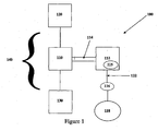
- Figure 1 illustrates a block diagram of a typical power switching configuration.
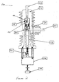
- Figure 2 illustrates a cross sectional view of a recloser used in the power generation and distribution industry.
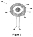
- Figure 3 illustrates an exploded cross sectional view of a current transformer installed in the power switching device.
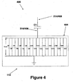
- Figure 4 illustrates a schematic diagram of a capacitive voltage divider circuit in accordance with one embodiment of the present invention.
- FIG. 1 shows a block diagram of a typical power switching configuration 100.
- the power switching configuration 100 has a power switching device 110 which is connected in series between a power source 120 and a load 130.
- the electrical circuit between the power source 120 and the load 130 is referred to as the power distribution circuit 140.
- the power switching device 110 is connected to a controller 112 by a bidirectional communications bus 114.
- a microprocessor 115 provides the controller 112 with the processing capability to monitor the power switching device 110 for faults as well as operating conditions. In the preferred embodiment, a Motorola HC12D60 microprocessor is used.
- a user 118 configures the controller 112 and receives information from the controller 112 via a user interface 116.
- the user interface 116 connects to the controller 112 through a communication means 122.
- the distribution circuit 140 is shown as a single phase of a three phase circuit for ease of illustration. The other two phases are identical.
- the power switching device 110 connects the power source 120 to the load 130.
- a power source 120 used with the present invention is a substation that provides, for example, a 1 kilovolt(kV) up to 40kV source of three phase AC power.
- An individual distribution transformer or bank of transformers connected together comprises the load 130.
- the transformers may be three phase transformers for large industrial applications or single phase transformers used to provide electricity to a residential consumer.
- Each power switching device 110 performs a preprogrammed response when a fault condition in the power distribution circuit 140 is detected by the controller 112.
- the fault interrupter opens once and remains open when a fault condition is detected.
- the breaker opens after a fault, but attempts to close before remaining open if the fault continues to exist.
- a recloser opens and closes multiple times when a fault condition exists. By opening and closing multiple times, the recloser attempts to clear the fault. Should the fault condition continue to exist, the recloser opens and remains open until reset manually. The recloser enters a "lock out" state when this occurs.
- a fault condition occurs when one phase of power becomes shorted to ground, phases become shorted to each other, or when lightning strikes the distribution circuit 140.
- the controller 112 monitors the voltage and current levels communicated to it by the power switching device 110.
- the power switching device 110 sends this information to the controller 112 through the bidirectional communications bus 114.
- the controller 112 signals the power switching device 110 to execute the preprogrammed response.
- Two example controllers 112 used with the present invention are the ICD (Intelligent Control Device) and the PCD (Programmable Control Device), manufactured by ABB Inc.
- a user 118 may be the utility craftsperson who is at the power switching device location.
- the craftsperson can use a laptop PC as the user interface 116 and connect directly to a serial port on the controller 112.
- the connection to the serial port is the communication means 122.
- Another user 118 may be the utility maintenance person remotely logged into the controller 112.
- the remotely located utility maintenance person uses a desktop PC for the user interface 116 and a modem configuration as the communication means 122 to connect to the controller 112.
- FIG. 2 A cross sectional view of a typical power switching device 110 in the form of a recloser 200 such as the OVR 1 Single Phase Recloser manufactured by ABB Inc. is illustrated in Figure 2 .
- Current flows through the recloser 200 from an H1 connector 212, through a vacuum interrupter 230 and a current transfer assembly 224 to an H2 connector 214.
- the vacuum interrupter 230 provides an enclosure that houses a stationary contact 232 and a moveable contact 234.
- the stationary contact 232 is directly connected to the H1 connector 212.
- the current transfer assembly 224 provides the electrical connection between the moveable contact 234 and the H2 connector 214.
- the current transformer 236 provides a current to the controller 112 that is proportional to the current flowing through the H2 connector 214.
- the controller 112 samples the proportional current and determines an appropriate value which is in turn conveyed to the user 118 through the user interface 116.
- FIG. 3 A cross-sectional view of the current transformer 236 along the axis X-X of Figure 2 is shown in Figure 3 .
- the current transformer 236 has wire wound around an annular shaped ferrous core 306 to form a winding 308.
- the winding 308 and magnetic core 306 are encased in an electrostatic shield 310.
- conductive tape or semi-conductive tape is used for the electrostatic shield 310.
- the electrostatic shield is an aluminum coating applied to the core 306 and winding 308.
- a layer of filler material 304 such as epoxy or polyurethane. This is the same material that is used for the housing 210 of the recloser 200.
- the current transformer 236 is electrically connected to the bidirectional communications bus 114 by the two winding leads 312 and the shield lead 314.
- the winding leads 312 are connected to the winding 308 and the shield lead 314 is connected to the shield 310.
- the bidirectional communications bus 114 routes the electrical signals from the winding leads 312 and the shield lead 314 to the controller 112 for processing. Inside the controller 112, the signals from the winding leads 312 are connected to a current sensing circuit (not shown) and the signal from the shield lead 314 is connected to a capacitive voltage divider circuit 400, one embodiment of which is shown in Fig. 4 .
- the layer 304 between the current transformer 236 and the H2 conductor 214 provides a consistent and predictable dielectric property between the shield 310 and the H2 connector 214.
- the combination of the shield 310, the layer 304, and the H2 connector 214 form a capacitor C1 which is shown in the schematic of Figure 4 .
- the capacitor C1 forms a high voltage leg of the capacitive voltage divider 400. In the previously described OVR-1 recloser 200, the capacitance of C1 is approximately 30-50 pF.
- the shield lead 314 connects to the low voltage leg 404 of the capacitive voltage divider 400.
- the low voltage leg 404 comprises individual capacitors C2-C21, which are connected between the shield 310 and ground. Removing one or more of the capacitors C2-C21 allows the capacitive voltage divider 400 to be tuned. This is explained in further detail in subsequent sections. Alternatively, should the capacitive voltage divider 400 not need to be adjusted, the capacitors C2-C21 may be combined into one single capacitor.
- the output voltage V out across the low voltage leg 404 is sent to an amplification stage (not shown) and then to an analog to digital converter circuit stage (not shown).
- the microprocessor 115 has several built-in A/D converters which are connected to the amplification stage. The microprocessor 115 determines the appropriate voltage potential value from the output of the A/D converter and that value is displayed to a user 118 via the user interface 116.
- the capacitors C2-C21 of the low voltage leg 404 are mounted on a printed circuit board (not shown) within the controller 112 and are easily accessible by manufacturing personnel or a craftsperson.
- the capacitors C4-C21 may be removed by breaking or cutting them off the printed circuit board while capacitors C2 and C3 are not removable. Removing one or all of the capacitors C4-C21 reduces the total capacitance of the low voltage leg 404 and increases the value of the output voltage V out .
- the values of the capacitors C4-C21 are chosen to allow the capacitive voltage divider 400 to be tuned with as much granularity as possible.
- capacitors C2-C21 the capacitance for each of capacitors C2-C21 and the percent change in V out resulting from removal of each of capacitors C4-C21 are shown in the table below.
- the voltage divider 400 is tuned to account for any variance in the capacitance of the high voltage leg C1.
- the tuned capacitance ratio of the low voltage leg 404 to the high voltage leg C1 is approximately 10,000:1. This ratio was chosen to provide the controller circuitry (amplification stage and A/D conversion stage) with an AC voltage within a sampling area. Those skilled in the art appreciate that this ratio is also a de-facto industry standard. As an illustrative example, should the low voltage leg 404 of the capacitive voltage divider 400 need to be tuned down by 18.5%, capacitors C4, C5, C8, C16 and C17 are removed and the output voltage V out increases by 18.5%.
- the capacitors C4-21 within the controller 112 are accessible to manufacturing or utility personnel.
- the controller 112 may be paired with a power switching device 110.
- the capacitive voltage divider circuitry 400 may be adjusted for the unique capacitance value C1 of the power switching device 110 prior to shipment.
- the manufacturing person measures the capacitance of C1 and then removes the appropriate capacitors C4-C21 to achieve the 10,000:1 ratio. If the controller 112 is shipped to the field separately, the utility craftsperson may tune the voltage divider 400 at the installation site performing the same steps prior to bringing the power switching device 110 on line.
- the present invention may also be applied to power switching devices 110 using other types of shielded coils for use in measuring current and voltage, such as shielded Rogowski coils.
- the Rogowski coil is an air core toroidal coil placed around a conductor.
- the core of the Rogowski coil is constructed of a non-ferrous material.
- An alternating magnetic field within the coil, produced by the current flowing in the conductor, induces a voltage which is proportional to the rate of change of the current.
- the output of the Rogowski coil is sent to an integrator where the value of voltage is extrapolated.
- the voltage measured with the Rogowski coil is a function of the amount of current flowing through the power switching device 110.
- FIG. 4 does show the shield lead 406 of the Rogowski coil and the conductor 408 around which the air core toroidal coil of the Rogowski coil is placed.
- the capacitor C1 of circuit 400 is formed from the combination of the shield of the Rogowski coil, the conductor 408 and the air core there between.
- the air core is the dielectric of capacitor C1.
- the low voltage leg 404 of the capacitive voltage divider 400 is designed with the appropriate values for capacitors C2-C21 to provide the preferred ratio of 10,000:1.
- the present invention measures the voltage potential at the conductor 408 independentof the amount of current flowing through the power switching device 110.
Claims (13)
- Procédé de détermination d'un potentiel de tension sur un conducteur (214) dans un dispositif de commutation de puissance (110), consistant à :- prévoir un dispositif de mesure de courant (236) logé dans ledit dispositif de commutation de puissance (110), ledit dispositif de mesure de courant (236) entourant ledit conducteur (214) et étant conçu pour mesurer la circulation de courant dans ledit conducteur (214) ;- prévoir un blindage électrostatique (310) enfermant ledit dispositif de mesure de courant (236) et dans une relation d'espacement avec ledit conducteur (214) ;
caractérisé en ce que ledit procédé consiste en outre à :- prévoir un diélectrique (304) situé entre ledit blindage électrostatique et ledit conducteur de sorte que ledit diélectrique, ledit blindage électrostatique et ledit conducteur forment un premier condensateur (C1) ;- connecter électriquement ledit blindage électrostatique (310) à un ou plusieurs deuxièmes condensateurs (C2 à C21) ; et- mesurer le potentiel de tension aux bornes desdits un ou plusieurs deuxièmes condensateurs (C2 à C21). - Procédé selon la revendication 1, dans lequel ledit premier condensateur (C1) et lesdits un ou plusieurs deuxièmes condensateurs (C2 à C21) forment un diviseur de tension capacitif (400).
- Procédé selon la revendication 2, dans lequel ledit premier condensateur (C1) forme une branche haute tension dudit diviseur de tension capacitif (400), et lesdits un ou plusieurs deuxièmes condensateurs forment une branche basse tension (404) dudit diviseur de tension capacitif (400).
- Procédé selon la revendication 2, caractérisé en ce qu'il consiste en outre à ajuster ledit diviseur de tension capacitif (400) en retirant au moins l'un des deuxièmes condensateurs.
- Appareil de mesure de potentiel de tension pour mesurer un potentiel de tension sur un conducteur (214) dans un dispositif de commutation de puissance (110), comprenant :- un dispositif de mesure de courant (236) logé dans ledit dispositif de commutation de puissance et entourant ledit conducteur (214), ledit dispositif de mesure de courant (236) étant conçu pour mesurer la circulation de courant dans ledit conducteur (214) ;- un blindage électrostatique enfermant ledit dispositif de mesure de courant et qui est dans une relation d'espacement par rapport audit conducteur ;
caractérisé en ce que ledit appareil comprend en outre :- un diélectrique (304) situé entre ledit blindage électrostatique (310) et ledit conducteur (214) de sorte que ledit diélectrique (304), ledit blindage (310) et ledit conducteur (214) forment un premier condensateur (C1) ; et- un ou plusieurs deuxièmes condensateurs (C2 à C21) connectés électriquement audit blindage électrostatique (310), dans lequel un potentiel de tension est mesuré aux bornes desdits un ou plusieurs deuxièmes condensateurs (C2 à C21). - Appareil selon la revendication 5, dans lequel ledit diélectrique (304) comprend un matériau de remplissage.
- Appareil selon la revendication 6, dans lequel ledit matériau de remplissage comprend un époxy ou du polyuréthane.
- Appareil selon la revendication 5, dans lequel le blindage électrostatique (310) comprend une bande conductrice ou semi-conductrice.
- Appareil selon la revendication 5, dans lequel le blindage électrostatique (310) comprend un revêtement d'aluminium.
- Appareil selon la revendication 5, dans lequel le dispositif de mesure de courant (236) est un transformateur de courant.
- Appareil selon la revendication 5, dans lequel ledit premier condensateur et lesdits un ou plusieurs deuxièmes condensateurs forment un diviseur de tension capacitif (400).
- Appareil selon la revendication 11, dans lequel ledit premier condensateur forme une branche haute tension dudit diviseur de tension capacitif (400), et lesdits un ou plusieurs deuxièmes condensateurs forment une branche basse tension (404) dudit diviseur de tension capacitif (400).
- Appareil selon la revendication 5, dans lequel ledit dispositif de mesure de courant (236) comprend un enroulement de Rogowski.
Applications Claiming Priority (2)
| Application Number | Priority Date | Filing Date | Title |
|---|---|---|---|
| US58145104P | 2004-06-21 | 2004-06-21 | |
| PCT/US2005/021775 WO2006007456A2 (fr) | 2004-06-21 | 2005-06-21 | Methode et appareil pour mesurer la tension d'un dispositif de commutation d'alimentation |
Publications (2)
| Publication Number | Publication Date |
|---|---|
| EP1766421A2 EP1766421A2 (fr) | 2007-03-28 |
| EP1766421B1 true EP1766421B1 (fr) | 2011-10-05 |
Family
ID=35045408
Family Applications (1)
| Application Number | Title | Priority Date | Filing Date |
|---|---|---|---|
| EP05762595A Not-in-force EP1766421B1 (fr) | 2004-06-21 | 2005-06-21 | Methode et appareil pour mesurer la tension d'un conducteur dans un appareillage électrique à haute tension |
Country Status (12)
| Country | Link |
|---|---|
| US (1) | US7550960B2 (fr) |
| EP (1) | EP1766421B1 (fr) |
| KR (1) | KR100899301B1 (fr) |
| CN (1) | CN1977173A (fr) |
| AT (1) | ATE527547T1 (fr) |
| AU (1) | AU2005262428B2 (fr) |
| BR (1) | BRPI0512320B1 (fr) |
| CA (1) | CA2571140C (fr) |
| MX (1) | MXPA06015012A (fr) |
| RU (1) | RU2385464C2 (fr) |
| WO (1) | WO2006007456A2 (fr) |
| ZA (1) | ZA200610635B (fr) |
Families Citing this family (20)
| Publication number | Priority date | Publication date | Assignee | Title |
|---|---|---|---|---|
| EP2136216B1 (fr) * | 2008-06-19 | 2012-01-11 | ABB Technology AG | Dispositif de mesure électrique combinée |
| ITBO20080079U1 (it) * | 2008-10-30 | 2010-04-30 | Lorenzo Peretto | Sistema costruttivo per un sensore capacitivo. |
| BRPI0901121A2 (pt) * | 2009-03-24 | 2010-12-21 | Ims Ind De Micro Sist S Eletronicos Ltda | sensor eletrÈnico para captura de sinal elétrico |
| US8163574B2 (en) | 2009-05-08 | 2012-04-24 | Eaton Corporaton | System and method for sensing voltage in medium-to-high voltage applications |
| US8487606B2 (en) | 2010-10-26 | 2013-07-16 | Eaton Corporation | Sensor assembly, trip unit including the same, and method of manufacturing a sensor assembly |
| US8564280B2 (en) * | 2011-01-31 | 2013-10-22 | Elster Solutions, Llc | Mechanical packaging and method for a single current sensor integrated into an electricity meter with a disconnect switch |
| US9472337B2 (en) * | 2011-04-14 | 2016-10-18 | Abb Schweiz Ag | Electrostatic shield for a transformer |
| RU2525581C1 (ru) * | 2012-12-26 | 2014-08-20 | Федеральное государственное бюджетное образовательное учреждение высшего профессионального образования "Московский государственный технологический университет "СТАНКИН" (ФГБОУ ВПО МГТУ "СТАНКИН") | Электронный датчик тока и напряжения на высоком потенциале |
| US9513316B2 (en) * | 2013-05-31 | 2016-12-06 | General Electric Company | System and method for a capacitive voltage sensor system |
| CN106170843B (zh) | 2014-04-14 | 2018-11-06 | Abb瑞士股份有限公司 | 具有嵌入在绝缘树脂中的真空断续器的用于中压或高压应用的嵌入式极部件 |
| RU2578726C1 (ru) * | 2014-10-29 | 2016-03-27 | Рустэм Газизович Хузяшев | Способ определения фазного напряжения, поверхностного сопротивления и тока утечки линейного подвесного изолятора воздушной линии электропередач и устройство для его осуществления |
| FR3032276B1 (fr) * | 2015-02-02 | 2018-08-31 | Schneider Electric Industries Sas | Capteur de courant et reseau electrique comprenant un tel capteur de courant |
| RU2649652C1 (ru) * | 2016-12-09 | 2018-04-04 | Российская Федерация, от имени которой выступает Государственная корпорация по атомной энергии "Росатом" (Госкорпорация "Росатом") | Емкостной делитель напряжения |
| DE102017130775A1 (de) * | 2017-12-20 | 2019-06-27 | Endress+Hauser SE+Co. KG | Feldgeräteelektronik für ein Feldgerät der Automatisierungstechnik |
| KR101997536B1 (ko) | 2018-05-08 | 2019-10-01 | 한국전력공사 | 회로 건전성 시험 장치, 이의 방법, 및 이 방법을 저장한 컴퓨터 판독 가능 저장 매체 |
| EP3699602A1 (fr) * | 2019-02-22 | 2020-08-26 | ABB Schweiz AG | Capteur de tension pour des mesures de tension moyenne ou haute |
| DE102019211950B3 (de) * | 2019-08-08 | 2020-11-26 | Siemens Aktiengesellschaft | Messen einer elektrischen Spannung an einem metallgekapselten Schaltgerät |
| GB2588631B (en) * | 2019-10-29 | 2022-03-23 | Tavrida Electric Holding Ag | Voltage sensor for electrical switchgear and electrical switchgear comprising same |
| KR20230059987A (ko) | 2021-10-27 | 2023-05-04 | 케이지모빌리티 주식회사 | 자기장을 이용한 고전압 검출장치 |
| KR20230126805A (ko) | 2022-02-24 | 2023-08-31 | 케이지모빌리티 주식회사 | 충전전류 자기장을 이용한 고전압 표시장치 |
Citations (1)
| Publication number | Priority date | Publication date | Assignee | Title |
|---|---|---|---|---|
| US4074193A (en) * | 1973-12-20 | 1978-02-14 | Siemens Aktiengesellschaft | Combined current and voltage measuring apparatus |
Family Cites Families (24)
| Publication number | Priority date | Publication date | Assignee | Title |
|---|---|---|---|---|
| US2327774A (en) | 1940-10-31 | 1943-08-24 | Gen Electric | High frequency current transformer |
| US2947958A (en) | 1955-07-18 | 1960-08-02 | Gen Electric | High voltage current transformer |
| FR1283978A (fr) | 1960-12-29 | 1962-02-09 | Acec | Traversée pour appareils électriques |
| US3380009A (en) | 1967-03-10 | 1968-04-23 | Gen Electric | High voltage current transformer |
| US3729675A (en) * | 1970-02-13 | 1973-04-24 | R Vosteen | High level non-contacting dynamic voltage follower for voltage measurement of electrostatically charged surfaces |
| US3851287A (en) | 1972-02-09 | 1974-11-26 | Litton Systems Inc | Low leakage current electrical isolation system |
| DE2341073B2 (de) | 1973-08-10 | 1980-01-10 | Siemens Ag, 1000 Berlin Und 8000 Muenchen | Meßeinrichtung für die Spannung in einer gekapselten Hochspannungsschaltanlage |
| US4241373A (en) * | 1979-03-30 | 1980-12-23 | Mcgraw-Edison Company | Switchgear voltage sensor |
| US4316254A (en) * | 1979-05-25 | 1982-02-16 | Electric Power Research Institute, Inc. | Portable phase angle meter instrument |
| US4804908A (en) * | 1983-10-03 | 1989-02-14 | Mitchell Roger E | Digital meter |
| FR2564594B1 (fr) * | 1984-05-21 | 1986-09-12 | Merlin Gerin | Capteur de courant a noyau amagnetique |
| CA1277371C (fr) | 1984-07-02 | 1990-12-04 | Graham J. Clarke | Dispositif a haute tension |
| DE3740468A1 (de) * | 1987-11-28 | 1989-06-08 | Kernforschungsz Karlsruhe | Vorrichtung zur beruehrungslosen messung statischer und/oder zeitlich veraenderlicher elektrischer felder |
| US5107201A (en) * | 1990-12-11 | 1992-04-21 | Ogle John S | High voltage oscilloscope probe with wide frequency response |
| DE4121654A1 (de) * | 1991-06-29 | 1993-01-07 | Asea Brown Boveri | Kombinierter strom- und spannungswandler fuer eine metallgekapselte gasisolierte hochspannungsanlage |
| US5471144A (en) * | 1993-09-27 | 1995-11-28 | Square D Company | System for monitoring the insulation quality of step graded insulated high voltage apparatus |
| US6344959B1 (en) | 1998-05-01 | 2002-02-05 | Unitrode Corporation | Method for sensing the output voltage of a charge pump circuit without applying a load to the output stage |
| US6470283B1 (en) * | 1999-11-15 | 2002-10-22 | Thomas G. Edel | Non-contact self-powered electric power monitor |
| US6489782B1 (en) * | 2000-12-21 | 2002-12-03 | Eaton Corporation | Electrical system with a stand-off insulator-sensor for on-line partial discharge monitoring of the state of high-voltage insulation |
| US6688086B2 (en) * | 2001-03-14 | 2004-02-10 | Weaver Leather Goods, Inc. | Cinch buckle and method of use |
| US6965199B2 (en) * | 2001-03-27 | 2005-11-15 | The University Of North Carolina At Chapel Hill | Coated electrode with enhanced electron emission and ignition characteristics |
| US6529013B2 (en) * | 2001-05-31 | 2003-03-04 | Mcgraw-Edison Company | Three-phase voltage sensor with active crosstalk cancellation |
| US6717395B2 (en) * | 2001-05-31 | 2004-04-06 | Mcgraw-Edison Company | Current transformer based high voltage measurement apparatus |
| US6888086B2 (en) | 2002-09-30 | 2005-05-03 | Cooper Technologies Company | Solid dielectric encapsulated interrupter |
-
2005
- 2005-06-21 CA CA2571140A patent/CA2571140C/fr active Active
- 2005-06-21 RU RU2007102048/28A patent/RU2385464C2/ru not_active IP Right Cessation
- 2005-06-21 WO PCT/US2005/021775 patent/WO2006007456A2/fr active Application Filing
- 2005-06-21 CN CNA2005800203397A patent/CN1977173A/zh active Pending
- 2005-06-21 MX MXPA06015012A patent/MXPA06015012A/es active IP Right Grant
- 2005-06-21 AU AU2005262428A patent/AU2005262428B2/en not_active Ceased
- 2005-06-21 US US11/157,595 patent/US7550960B2/en active Active
- 2005-06-21 AT AT05762595T patent/ATE527547T1/de not_active IP Right Cessation
- 2005-06-21 KR KR1020077001441A patent/KR100899301B1/ko active IP Right Grant
- 2005-06-21 EP EP05762595A patent/EP1766421B1/fr not_active Not-in-force
- 2005-06-21 BR BRPI0512320-8A patent/BRPI0512320B1/pt active IP Right Grant
-
2006
- 2006-12-18 ZA ZA2006/10635A patent/ZA200610635B/en unknown
Patent Citations (1)
| Publication number | Priority date | Publication date | Assignee | Title |
|---|---|---|---|---|
| US4074193A (en) * | 1973-12-20 | 1978-02-14 | Siemens Aktiengesellschaft | Combined current and voltage measuring apparatus |
Also Published As
| Publication number | Publication date |
|---|---|
| AU2005262428B2 (en) | 2009-02-19 |
| RU2007102048A (ru) | 2008-07-27 |
| US20050280423A1 (en) | 2005-12-22 |
| KR20070037747A (ko) | 2007-04-06 |
| CN1977173A (zh) | 2007-06-06 |
| KR100899301B1 (ko) | 2009-05-27 |
| ATE527547T1 (de) | 2011-10-15 |
| US7550960B2 (en) | 2009-06-23 |
| CA2571140C (fr) | 2011-04-26 |
| RU2385464C2 (ru) | 2010-03-27 |
| EP1766421A2 (fr) | 2007-03-28 |
| CA2571140A1 (fr) | 2006-01-19 |
| MXPA06015012A (es) | 2007-05-09 |
| WO2006007456A3 (fr) | 2006-02-23 |
| WO2006007456A2 (fr) | 2006-01-19 |
| BRPI0512320B1 (pt) | 2017-10-17 |
| BRPI0512320A (pt) | 2008-02-26 |
| AU2005262428A1 (en) | 2006-01-19 |
| ZA200610635B (en) | 2011-03-30 |
Similar Documents
| Publication | Publication Date | Title |
|---|---|---|
| EP1766421B1 (fr) | Methode et appareil pour mesurer la tension d'un conducteur dans un appareillage électrique à haute tension | |
| CN101416364B (zh) | 用于保护的高速自动断路器 | |
| EP0792465B1 (fr) | Dispositif de detection des decharges electriques dans un objet a tester | |
| CN1908681B (zh) | 一种交流电力系统过电压监测传感器 | |
| CN102044863B (zh) | 包含多个罗戈夫斯基线圈的电气开关设备及其校准方法 | |
| US7126348B2 (en) | Method and a device for voltage measurement in a high-voltage conductor | |
| EP0820651A1 (fr) | Systeme de detection de defauts d'arc | |
| TW471204B (en) | Gas insulated device and failure rating method | |
| CN107884645A (zh) | 基于电压比较的电力电容器运行状态监测方法 | |
| CN106249054A (zh) | 电容式电压互感器及其一体化检测传感器 | |
| US4280093A (en) | Zero-current detector for high voltage DC transmission line | |
| CN206906454U (zh) | 配电设备用一二次融合三相智能电流电压一体化互感器 | |
| CN211265136U (zh) | 一种用于10kV线路的新型智能化绝缘子及装置 | |
| CN113092844A (zh) | 一种电压电流一体式传感装置及卡套 | |
| CN206992512U (zh) | 一种智能型低压综合配电柜 | |
| Goodeve et al. | Experience with compact epoxy-mica capacitors for rotating machine partial discharge detection | |
| US7275001B2 (en) | Method for measuring electrical current levels in a power switching device | |
| Sandler et al. | Measurement Systems for High Voltage Transients in Power Networks | |
| CN110687403B (zh) | 一种配电网单相接地故障检测方法及装置 | |
| Hamilton et al. | Application of transistor techniques to relays and protection for power systems | |
| AU740932B2 (en) | Method and apparatus for monitoring AC circuits | |
| Wei et al. | Key technology and application of primary and secondary fusion power distribution switchgear test and detection | |
| CA1157095A (fr) | Detecteur de courants nuls pour ligne de transmission a haute tension continue | |
| Fedorov | Switching overvoltages in an operational dc grid | |
| MXPA96003421A (en) | Monitoring system for high voltage appliance isolates |
Legal Events
| Date | Code | Title | Description |
|---|---|---|---|
| PUAI | Public reference made under article 153(3) epc to a published international application that has entered the european phase |
Free format text: ORIGINAL CODE: 0009012 |
|
| 17P | Request for examination filed |
Effective date: 20070115 |
|
| AK | Designated contracting states |
Kind code of ref document: A2 Designated state(s): AT BE BG CH CY CZ DE DK EE ES FI FR GB GR HU IE IS IT LI LT LU MC NL PL PT RO SE SI SK TR |
|
| DAX | Request for extension of the european patent (deleted) | ||
| 17Q | First examination report despatched |
Effective date: 20100303 |
|
| GRAP | Despatch of communication of intention to grant a patent |
Free format text: ORIGINAL CODE: EPIDOSNIGR1 |
|
| RTI1 | Title (correction) |
Free format text: A METHOD AND AN APPARATUS FOR MEASURING VOLTAGE ON A CONDUCTOR IN A POWER SWITCHING DEVICE |
|
| GRAS | Grant fee paid |
Free format text: ORIGINAL CODE: EPIDOSNIGR3 |
|
| GRAA | (expected) grant |
Free format text: ORIGINAL CODE: 0009210 |
|
| AK | Designated contracting states |
Kind code of ref document: B1 Designated state(s): AT BE BG CH CY CZ DE DK EE ES FI FR GB GR HU IE IS IT LI LT LU MC NL PL PT RO SE SI SK TR |
|
| REG | Reference to a national code |
Ref country code: GB Ref legal event code: FG4D |
|
| REG | Reference to a national code |
Ref country code: CH Ref legal event code: EP |
|
| REG | Reference to a national code |
Ref country code: IE Ref legal event code: FG4D |
|
| REG | Reference to a national code |
Ref country code: DE Ref legal event code: R081 Ref document number: 602005030421 Country of ref document: DE Owner name: ABB SCHWEIZ AG, CH Free format text: FORMER OWNER: ABB TECHNOLOGY AG, ZUERICH, CH |
|
| REG | Reference to a national code |
Ref country code: DE Ref legal event code: R096 Ref document number: 602005030421 Country of ref document: DE Effective date: 20111229 |
|
| REG | Reference to a national code |
Ref country code: NL Ref legal event code: VDEP Effective date: 20111005 |
|
| PG25 | Lapsed in a contracting state [announced via postgrant information from national office to epo] |
Ref country code: SI Free format text: LAPSE BECAUSE OF FAILURE TO SUBMIT A TRANSLATION OF THE DESCRIPTION OR TO PAY THE FEE WITHIN THE PRESCRIBED TIME-LIMIT Effective date: 20111005 |
|
| LTIE | Lt: invalidation of european patent or patent extension |
Effective date: 20111005 |
|
| REG | Reference to a national code |
Ref country code: AT Ref legal event code: MK05 Ref document number: 527547 Country of ref document: AT Kind code of ref document: T Effective date: 20111005 |
|
| PG25 | Lapsed in a contracting state [announced via postgrant information from national office to epo] |
Ref country code: LT Free format text: LAPSE BECAUSE OF FAILURE TO SUBMIT A TRANSLATION OF THE DESCRIPTION OR TO PAY THE FEE WITHIN THE PRESCRIBED TIME-LIMIT Effective date: 20111005 Ref country code: BE Free format text: LAPSE BECAUSE OF FAILURE TO SUBMIT A TRANSLATION OF THE DESCRIPTION OR TO PAY THE FEE WITHIN THE PRESCRIBED TIME-LIMIT Effective date: 20111005 Ref country code: IS Free format text: LAPSE BECAUSE OF FAILURE TO SUBMIT A TRANSLATION OF THE DESCRIPTION OR TO PAY THE FEE WITHIN THE PRESCRIBED TIME-LIMIT Effective date: 20120205 |
|
| PG25 | Lapsed in a contracting state [announced via postgrant information from national office to epo] |
Ref country code: NL Free format text: LAPSE BECAUSE OF FAILURE TO SUBMIT A TRANSLATION OF THE DESCRIPTION OR TO PAY THE FEE WITHIN THE PRESCRIBED TIME-LIMIT Effective date: 20111005 Ref country code: PT Free format text: LAPSE BECAUSE OF FAILURE TO SUBMIT A TRANSLATION OF THE DESCRIPTION OR TO PAY THE FEE WITHIN THE PRESCRIBED TIME-LIMIT Effective date: 20120206 Ref country code: GR Free format text: LAPSE BECAUSE OF FAILURE TO SUBMIT A TRANSLATION OF THE DESCRIPTION OR TO PAY THE FEE WITHIN THE PRESCRIBED TIME-LIMIT Effective date: 20120106 Ref country code: SE Free format text: LAPSE BECAUSE OF FAILURE TO SUBMIT A TRANSLATION OF THE DESCRIPTION OR TO PAY THE FEE WITHIN THE PRESCRIBED TIME-LIMIT Effective date: 20111005 |
|
| PG25 | Lapsed in a contracting state [announced via postgrant information from national office to epo] |
Ref country code: CY Free format text: LAPSE BECAUSE OF FAILURE TO SUBMIT A TRANSLATION OF THE DESCRIPTION OR TO PAY THE FEE WITHIN THE PRESCRIBED TIME-LIMIT Effective date: 20111005 |
|
| PLBI | Opposition filed |
Free format text: ORIGINAL CODE: 0009260 |
|
| PG25 | Lapsed in a contracting state [announced via postgrant information from national office to epo] |
Ref country code: EE Free format text: LAPSE BECAUSE OF FAILURE TO SUBMIT A TRANSLATION OF THE DESCRIPTION OR TO PAY THE FEE WITHIN THE PRESCRIBED TIME-LIMIT Effective date: 20111005 Ref country code: SK Free format text: LAPSE BECAUSE OF FAILURE TO SUBMIT A TRANSLATION OF THE DESCRIPTION OR TO PAY THE FEE WITHIN THE PRESCRIBED TIME-LIMIT Effective date: 20111005 Ref country code: CZ Free format text: LAPSE BECAUSE OF FAILURE TO SUBMIT A TRANSLATION OF THE DESCRIPTION OR TO PAY THE FEE WITHIN THE PRESCRIBED TIME-LIMIT Effective date: 20111005 Ref country code: BG Free format text: LAPSE BECAUSE OF FAILURE TO SUBMIT A TRANSLATION OF THE DESCRIPTION OR TO PAY THE FEE WITHIN THE PRESCRIBED TIME-LIMIT Effective date: 20120105 Ref country code: DK Free format text: LAPSE BECAUSE OF FAILURE TO SUBMIT A TRANSLATION OF THE DESCRIPTION OR TO PAY THE FEE WITHIN THE PRESCRIBED TIME-LIMIT Effective date: 20111005 |
|
| 26 | Opposition filed |
Opponent name: SIEMENS AG Effective date: 20120705 |
|
| PLAX | Notice of opposition and request to file observation + time limit sent |
Free format text: ORIGINAL CODE: EPIDOSNOBS2 |
|
| PG25 | Lapsed in a contracting state [announced via postgrant information from national office to epo] |
Ref country code: RO Free format text: LAPSE BECAUSE OF FAILURE TO SUBMIT A TRANSLATION OF THE DESCRIPTION OR TO PAY THE FEE WITHIN THE PRESCRIBED TIME-LIMIT Effective date: 20111005 Ref country code: PL Free format text: LAPSE BECAUSE OF FAILURE TO SUBMIT A TRANSLATION OF THE DESCRIPTION OR TO PAY THE FEE WITHIN THE PRESCRIBED TIME-LIMIT Effective date: 20111005 |
|
| REG | Reference to a national code |
Ref country code: DE Ref legal event code: R026 Ref document number: 602005030421 Country of ref document: DE Effective date: 20120705 |
|
| PLBB | Reply of patent proprietor to notice(s) of opposition received |
Free format text: ORIGINAL CODE: EPIDOSNOBS3 |
|
| PG25 | Lapsed in a contracting state [announced via postgrant information from national office to epo] |
Ref country code: AT Free format text: LAPSE BECAUSE OF FAILURE TO SUBMIT A TRANSLATION OF THE DESCRIPTION OR TO PAY THE FEE WITHIN THE PRESCRIBED TIME-LIMIT Effective date: 20111005 Ref country code: MC Free format text: LAPSE BECAUSE OF NON-PAYMENT OF DUE FEES Effective date: 20120630 |
|
| REG | Reference to a national code |
Ref country code: CH Ref legal event code: PL |
|
| REG | Reference to a national code |
Ref country code: CH Ref legal event code: PL |
|
| REG | Reference to a national code |
Ref country code: IE Ref legal event code: MM4A |
|
| PG25 | Lapsed in a contracting state [announced via postgrant information from national office to epo] |
Ref country code: LI Free format text: LAPSE BECAUSE OF NON-PAYMENT OF DUE FEES Effective date: 20120630 Ref country code: ES Free format text: LAPSE BECAUSE OF FAILURE TO SUBMIT A TRANSLATION OF THE DESCRIPTION OR TO PAY THE FEE WITHIN THE PRESCRIBED TIME-LIMIT Effective date: 20120116 Ref country code: IE Free format text: LAPSE BECAUSE OF NON-PAYMENT OF DUE FEES Effective date: 20120621 Ref country code: CH Free format text: LAPSE BECAUSE OF NON-PAYMENT OF DUE FEES Effective date: 20120630 |
|
| PG25 | Lapsed in a contracting state [announced via postgrant information from national office to epo] |
Ref country code: TR Free format text: LAPSE BECAUSE OF FAILURE TO SUBMIT A TRANSLATION OF THE DESCRIPTION OR TO PAY THE FEE WITHIN THE PRESCRIBED TIME-LIMIT Effective date: 20111005 |
|
| PG25 | Lapsed in a contracting state [announced via postgrant information from national office to epo] |
Ref country code: LU Free format text: LAPSE BECAUSE OF NON-PAYMENT OF DUE FEES Effective date: 20120621 |
|
| PG25 | Lapsed in a contracting state [announced via postgrant information from national office to epo] |
Ref country code: HU Free format text: LAPSE BECAUSE OF FAILURE TO SUBMIT A TRANSLATION OF THE DESCRIPTION OR TO PAY THE FEE WITHIN THE PRESCRIBED TIME-LIMIT Effective date: 20050621 |
|
| REG | Reference to a national code |
Ref country code: DE Ref legal event code: R100 Ref document number: 602005030421 Country of ref document: DE |
|
| PLCK | Communication despatched that opposition was rejected |
Free format text: ORIGINAL CODE: EPIDOSNREJ1 |
|
| PLBN | Opposition rejected |
Free format text: ORIGINAL CODE: 0009273 |
|
| STAA | Information on the status of an ep patent application or granted ep patent |
Free format text: STATUS: OPPOSITION REJECTED |
|
| 27O | Opposition rejected |
Effective date: 20141212 |
|
| REG | Reference to a national code |
Ref country code: FR Ref legal event code: PLFP Year of fee payment: 12 |
|
| REG | Reference to a national code |
Ref country code: DE Ref legal event code: R081 Ref document number: 602005030421 Country of ref document: DE Owner name: ABB SCHWEIZ AG, CH Free format text: FORMER OWNER: ABB TECHNOLOGY AG, ZUERICH, CH Ref country code: DE Ref legal event code: R082 Ref document number: 602005030421 Country of ref document: DE Representative=s name: KUHNEN & WACKER PATENT- UND RECHTSANWALTSBUERO, DE |
|
| REG | Reference to a national code |
Ref country code: FR Ref legal event code: PLFP Year of fee payment: 13 |
|
| REG | Reference to a national code |
Ref country code: GB Ref legal event code: 732E Free format text: REGISTERED BETWEEN 20180426 AND 20180502 |
|
| REG | Reference to a national code |
Ref country code: FR Ref legal event code: PLFP Year of fee payment: 14 |
|
| REG | Reference to a national code |
Ref country code: FR Ref legal event code: TP Owner name: ABB SCHWEIZ AG, CH Effective date: 20180912 |
|
| PGFP | Annual fee paid to national office [announced via postgrant information from national office to epo] |
Ref country code: IT Payment date: 20190624 Year of fee payment: 15 Ref country code: DE Payment date: 20190619 Year of fee payment: 15 Ref country code: FI Payment date: 20190620 Year of fee payment: 15 |
|
| PGFP | Annual fee paid to national office [announced via postgrant information from national office to epo] |
Ref country code: FR Payment date: 20190619 Year of fee payment: 15 |
|
| PGFP | Annual fee paid to national office [announced via postgrant information from national office to epo] |
Ref country code: GB Payment date: 20190619 Year of fee payment: 15 |
|
| REG | Reference to a national code |
Ref country code: DE Ref legal event code: R119 Ref document number: 602005030421 Country of ref document: DE |
|
| REG | Reference to a national code |
Ref country code: FI Ref legal event code: MAE |
|
| PG25 | Lapsed in a contracting state [announced via postgrant information from national office to epo] |
Ref country code: FI Free format text: LAPSE BECAUSE OF NON-PAYMENT OF DUE FEES Effective date: 20200621 |
|
| GBPC | Gb: european patent ceased through non-payment of renewal fee |
Effective date: 20200621 |
|
| PG25 | Lapsed in a contracting state [announced via postgrant information from national office to epo] |
Ref country code: GB Free format text: LAPSE BECAUSE OF NON-PAYMENT OF DUE FEES Effective date: 20200621 Ref country code: FR Free format text: LAPSE BECAUSE OF NON-PAYMENT OF DUE FEES Effective date: 20200630 |
|
| PG25 | Lapsed in a contracting state [announced via postgrant information from national office to epo] |
Ref country code: DE Free format text: LAPSE BECAUSE OF NON-PAYMENT OF DUE FEES Effective date: 20210101 |
|
| PG25 | Lapsed in a contracting state [announced via postgrant information from national office to epo] |
Ref country code: IT Free format text: LAPSE BECAUSE OF NON-PAYMENT OF DUE FEES Effective date: 20200621 |