EP1766261B1 - A method and system for controlling helicopter vibrations - Google Patents
A method and system for controlling helicopter vibrations Download PDFInfo
- Publication number
- EP1766261B1 EP1766261B1 EP05856808A EP05856808A EP1766261B1 EP 1766261 B1 EP1766261 B1 EP 1766261B1 EP 05856808 A EP05856808 A EP 05856808A EP 05856808 A EP05856808 A EP 05856808A EP 1766261 B1 EP1766261 B1 EP 1766261B1
- Authority
- EP
- European Patent Office
- Prior art keywords
- resonant actuator
- resonant
- actuator
- control system
- electronic control
- Prior art date
- Legal status (The legal status is an assumption and is not a legal conclusion. Google has not performed a legal analysis and makes no representation as to the accuracy of the status listed.)
- Ceased
Links
- 238000000034 method Methods 0.000 title claims abstract description 68
- 238000013016 damping Methods 0.000 claims description 46
- 238000004519 manufacturing process Methods 0.000 claims description 8
- 230000001276 controlling effect Effects 0.000 description 22
- 238000006073 displacement reaction Methods 0.000 description 15
- 239000002184 metal Substances 0.000 description 10
- 230000004044 response Effects 0.000 description 10
- 230000032683 aging Effects 0.000 description 8
- 238000005457 optimization Methods 0.000 description 6
- 230000005672 electromagnetic field Effects 0.000 description 5
- 238000001914 filtration Methods 0.000 description 4
- 238000012360 testing method Methods 0.000 description 4
- 238000007493 shaping process Methods 0.000 description 3
- 230000008859 change Effects 0.000 description 2
- 238000012986 modification Methods 0.000 description 2
- 230000004048 modification Effects 0.000 description 2
- 239000006096 absorbing agent Substances 0.000 description 1
- 230000001133 acceleration Effects 0.000 description 1
- 230000001419 dependent effect Effects 0.000 description 1
- 230000001105 regulatory effect Effects 0.000 description 1
Images





Classifications
-
- F—MECHANICAL ENGINEERING; LIGHTING; HEATING; WEAPONS; BLASTING
- F16—ENGINEERING ELEMENTS AND UNITS; GENERAL MEASURES FOR PRODUCING AND MAINTAINING EFFECTIVE FUNCTIONING OF MACHINES OR INSTALLATIONS; THERMAL INSULATION IN GENERAL
- F16F—SPRINGS; SHOCK-ABSORBERS; MEANS FOR DAMPING VIBRATION
- F16F7/00—Vibration-dampers; Shock-absorbers
- F16F7/10—Vibration-dampers; Shock-absorbers using inertia effect
- F16F7/1005—Vibration-dampers; Shock-absorbers using inertia effect characterised by active control of the mass
- F16F7/1011—Vibration-dampers; Shock-absorbers using inertia effect characterised by active control of the mass by electromagnetic means
-
- B—PERFORMING OPERATIONS; TRANSPORTING
- B64—AIRCRAFT; AVIATION; COSMONAUTICS
- B64C—AEROPLANES; HELICOPTERS
- B64C27/00—Rotorcraft; Rotors peculiar thereto
- B64C27/001—Vibration damping devices
-
- B—PERFORMING OPERATIONS; TRANSPORTING
- B64—AIRCRAFT; AVIATION; COSMONAUTICS
- B64C—AEROPLANES; HELICOPTERS
- B64C27/00—Rotorcraft; Rotors peculiar thereto
- B64C27/001—Vibration damping devices
- B64C2027/005—Vibration damping devices using suspended masses
Definitions
- the present invention relates to a method/system for controlling problematic vibrations. More particularly the invention relates to a method and system for controlling aircraft vehicle vibrations, particularly a method and system for canceling problematic rotary wing helicopter vibrations.
- Helicopter vibrations are particularly troublesome in that they can cause fatigue and wear on the equipment and occupants in the aircraft.
- vibrations are particularly problematic in that they can damage the actual structure and components that make up the vehicle in addition to the contents of the vehicle.
- US-A-4922159 a vibration control actuator for controlling vibration of space deployed structures and seeks to remove any resonant component in the actuator.
- US-A-5920173 describes a vibration absorber.
- US-A-4497098 describes an instrument taken driver for providing a regulated beat or amplitude.
- the invention includes a vibration canceling force generator for actively generating a vibration canceling force, as defined in claim 1.
- the vibration canceling force generator includes a resonant actuator having a natural resonant frequency, and a resonant actuator electronic control system having a command input for receiving a command signal with the resonant actuator electronic control system providing an electrical drive current to the resonant actuator to drive the resonant actuator about the resonant frequency when commanded by a received command signal, and the resonant actuator has a feedback output with the feedback output fed back into the resonant actuator electronic control system wherein the resonant actuator electronic control system adjusts the electrical drive current based on the resonant actuator feedback output to generate the vibration canceling force.
- the invention includes a method of making a vibration canceling force generator as defined in claim 2.
- the method includes providing a resonant actuator having a natural resonant frequency, providing a resonant actuator electronic control system having a command input for receiving a command signal and a power amplifier for providing an electrical drive current to drive the resonant actuator, and connecting the resonant actuator with the resonant actuator electronic control system wherein the resonant actuator electronic control system electrical drive current drives the resonant actuator about the natural resonant frequency when commanded by a received command signal, with the resonant actuator feeding an electrical output back into the resonant actuator electronic control system wherein the resonant actuator electronic control system adjusts the electrical drive current based on the resonant actuator electrical output.
- the invention includes a method of controlling vibrations as defined in claim 3.
- the method includes providing a resonant actuator having a natural resonant frequency, providing a resonant actuator electronic control system for providing an electrical drive current to drive the resonant actuator, connecting the resonant actuator with the resonant actuator electronic control system, and driving the resonant actuator about the natural resonant frequency with the resonant actuator feeding an electrical output back into the resonant actuator electronic control system and adjusting the electrical drive current based on the resonant actuator electrical output.
- the invention includes a vehicle vibration canceling system as defined in claim 4.
- the vehicle vibration canceling system includes a resonant actuator having a natural resonant frequency.
- the vehicle vibration canceling system includes a resonant actuator electronic controller for providing an electrical drive current to the resonant actuator to drive the resonant actuator about the resonant frequency.
- the resonant actuator has a feedback electrical output with the feedback electrical output fed back into the resonant actuator electronic controller wherein said resonant actuator electronic controller adjusts said electrical drive current based on said resonant actuator feedback electrical output.
- the invention includes a method of making a helicopter vibration canceling system as defined in claim 5.
- the method includes providing a resonant actuator having a natural resonant frequency.
- the method includes providing a resonant actuator electronic control system for providing an electrical drive current to drive said resonant actuator.
- the method includes connecting the resonant actuator with the resonant actuator electronic control system wherein the resonant actuator electronic control system electrical drive current drives the resonant actuator about the natural resonant frequency with said resonant actuator feeding an electrical output back into the resonant actuator electronic control system wherein the resonant actuator electronic control system adjusts the electrical drive current based on the resonant actuator electrical output.
- the invention includes a method of controlling helicopter vibrations as defined in claim 6.
- the method includes providing a resonant actuator having a natural resonant frequency.
- the method includes mounting the resonant actuator in a helicopter.
- the method includes providing a resonant actuator electronic control system for providing an electrical drive current to drive the resonant actuator.
- the method includes connecting the resonant actuator with the resonant actuator electronic control system.
- the method includes driving the resonant actuator about the natural resonant frequency with the resonant actuator feeding an electrical output back into the resonant actuator electronic control system and adjusting the electrical drive current based on the resonant actuator electrical output.
- the invention comprises a vibration canceling force generator for actively generating a vibration canceling force.
- the vibration canceling force generator includes a resonant actuator having a natural resonant frequency, and a resonant actuator electronic control system with the resonant actuator electronic control system providing an electrical drive current to the resonant actuator to drive the resonant actuator about the resonant frequency when commanded.
- the resonant actuator has a feedback output with the feedback output fed back into the resonant actuator electronic control system wherein the resonant actuator electronic control system adjusts the electrical drive current based on the resonant actuator feedback output to generate the vibration canceling force.
- the invention includes a vibration canceling force generator for actively generating a vibration canceling force.
- the vibration canceling force generator includes a resonant actuator having a natural resonant frequency, and a resonant actuator electronic control system having a command input for receiving a command signal with the resonant actuator electronic control system providing an electrical drive current to the resonant actuator to drive the resonant actuator about the resonant frequency when commanded by a received command signal, and the resonant actuator has a feedback output with the feedback output fed back into the resonant actuator electronic control system wherein the resonant actuator electronic control system adjusts the electrical drive current based on the resonant actuator feedback output to generate the vibration canceling force. As shown in FIG.
- the vibration canceling force generator 20 actively generates a vibration canceling force 22 which destructively interferes with and cancels an unwanted vibration force in a structure 50 that it is attached to.
- the vibration canceling force generator 20 preferably includes a linear voice coil resonant actuator 24 having a natural resonant frequency 46.
- the resonant actuator 24 is an electromagnetically driven sprung mass 26 suspended on resilient metal flexures 32.
- the EM (ElectroMagnetic) driven mass 26 is preferably suspended on a horizontal beam stack of multiple layers of resilient metal flexures 32, which are preferably supported by two vertical side resilient metal flexures post plates, to provide a sprung mass that can be electromagnetically driven to oscillate at its natural resonant frequency.
- the resonant actuator sprung mass is driven by modulating an electromagnetic field so the sprung mass is attracted and repelled by the EM field at its resonant frequency.
- the resonant actuator sprung mass includes a permanent magnet 28 in alignment with an electromagnetic coil 30, wherein a electrical drive current supplied to the EM coil 30 drives the sprung mass at resonance.
- the vibration canceling force generator 20 includes a resonant actuator electronic control system 34.
- the resonant actuator electronic control system 34 has a command input 36 for receiving a command signal 38 and the resonant actuator electronic control system includes a power amplifier 40 that produces the electrical drive current (i).
- the resonant actuator electronic control system 34 provides an electrical drive current 42 to the resonant actuator 24 to drive the resonant actuator about the resonant frequency when commanded by a received command signal 38, with the resonant actuator having a feedback output 44 fed back into the resonant actuator electronic control system wherein the resonant actuator electronic control system adjusts the electrical drive current (i) based on the resonant actuator feedback output 44 to generate the vibration canceling force 22.
- the resonant actuator 24 has a resonant actuator natural resonant frequency in a range of 15 to 40 Hz, more preferably in the range of 15-30 Hz, and most preferably in the range of 18 to 26 Hz.
- the vibration canceling force generator 20 is able to adapt to an aging of the resonant actuator 24 that alters the resonant actuator natural resonant frequency changes over an extended operation life time frame such as from the aging of the metal flexures and loosening of the metal flexure fasteners and fixtures over time, preferably with the utilization of the resonant actuator feedback output 44 to adjust the drive current to the resonant actuators aging natural resonant frequency so that the control system produced drive current can follow an aging change in the natural frequency over an extended period of time.
- the resonant actuator 24 has a damping level less than four percent of critical damping, more preferably a damping level less than two percent of critical damping.
- the resonant actuator 24 is a lightly damped resonant actuator.
- the vibration canceling force generator 20 utilizes a resonant actuator 24 that has a lightly damped mass spring system highly resonant response, with the actuator driven at resonance because of its highly resonant response.
- the command signal 38 is an analog input voltage, which is received by command input 36 with the variable voltage input command signal commanding the electronic control system 34 to produce a force 22 to cancel the unwanted vibration force in the vibrating structure 50. As shown in FIG.
- the vibration canceling force generator includes electrical connector interfaces 52 for disengagably connecting the resonant actuator 24 to the resonant actuator electronic control system 34.
- Such an electrical connector interface preferably includes a feedback loop connector 52 and an electrical drive current connector 52, with the connector interfaces 52 providing for interchanging of actuators 24 with the control systems 34 and the replacement and swapping of resonant actuators 24.
- the resonant actuator feedback output 44 is an electrical output from the resonant actuator back into the control system 34.
- the actuator electrical output is directly fed from the actuator electrical output into the control system. In a preferred embodiment such as shown in FIG.
- the resonant actuator electrical feedback output 44 is an electrical charge flow rate (i) through the resonant actuator, with the current (i_act) through the actuator fed back into the control system, with the actuator drive current (i) controlled and limited to a maximum operation value.
- the control system uses the current (i_act) feedback 44 in controlling the drive current (i) to drive the actuator at resonance and without the need of shape filtering.
- the resonant actuator feedback output 44 is an electrical potential difference through the resonant actuator 24, with the voltage (v_act) across the actuator fed back into the control system, with the voltage in the actuator controlled and limited to a maximum value corresponding to the rated voltage for the actuator for maximum operation displacement of the actuator at resonance.
- the resonant actuator feedback output 44 is the electrical charge flow rate (i_act) through the resonant actuator and the electrical potential difference (v_act) through the resonant actuator, with both the voltage and current fed back from actuator 24.
- the invention comprise a method of making a vibration canceling force generator.
- the method includes providing a resonant actuator having a natural resonant frequency, providing a resonant actuator electronic control system having a power amplifier for providing an electrical drive current to drive the resonant actuator, and connecting the resonant actuator with the resonant actuator electronic control system wherein the resonant actuator electronic control system electrical drive current drives the resonant actuator about the natural resonant frequency when commanded by a received command signal, with the resonant actuator feeding an electrical output back into the resonant actuator electronic control system wherein the resonant actuator electronic control system adjusts the electrical drive current based on the resonant actuator electrical output.
- the invention includes a method of making a vibration canceling force generator 20.
- the method includes providing a resonant actuator 24 having a natural resonant frequency, providing a resonant actuator electronic control system 34 having a command input for receiving a command signal and a power amplifier for providing an electrical drive current (i) to drive the resonant actuator, and connecting the resonant actuator with the resonant actuator electronic control system wherein the resonant actuator electronic control system electrical drive current (i) drives the resonant actuator about the natural resonant frequency when commanded by a received command signal, with the resonant actuator feeding an electrical output 44 back into the resonant actuator electronic control system wherein the resonant actuator electronic control system adjusts the electrical drive current (i) based on the resonant actuator electrical output 44.
- Providing resonant actuator 24 preferably includes providing an electromagnetically driven voice coil, preferably a sprung mass 26 driven by modulating a electromagnetic field produced by an EM coil 30 so the sprung mass is attracted and repelled by the EM field and the actuator resonates at its natural resonant frequency.
- Providing the resonant actuator electronic control system 34 preferably includes providing a resonant actuator electronic control system having a command input 36 for receiving a command signal 38 and a power amplifier 40 for providing an electrical drive current (i) to drive the resonant actuator about its resonant frequency.
- the command signal 38 is an analog input voltage, with the analog variable voltage input command signal commanding the control system to produce a vibration canceling force 22 which destructively interferes with and cancels an unwanted vibration force in the structure 50 that the actuator 24 is attached to.
- the actuator electrical output 44 is fed back directly into the control system, preferably with no separate physical actuator motion sensor needed for producing the feedback output.
- the resonant actuator electrical output 44 includes an actuator sensor electrical output from an actuator sensor 54.
- the actuator sensor 54 provides an actuator sensor electrical output 44 relative to a physical motion characteristic of the actuator 24, such as a motion sensor measuring the motion of the moving mass 26.
- the actuator sensor 54 is an accelerometer mounted on the actuator driven sprung mass. In an embodiment the actuator sensor 54 is a velocity sensor measuring and sensing the velocity of the actuator driven sprung mass. In an embodiment the actuator sensor 54 is a displacement sensor measuring and sensing the displacement and position of the actuator driven sprung mass.
- Providing the resonant actuator 24, preferably includes providing a resonant actuator with a natural resonant frequency in the range of 15 to 40 Hz, more preferably 15-30Hz, and most preferably 18 to 26 Hz.
- Providing the resonant actuator 24, preferably includes providing a resonant actuator which has a damping level less than four percent of critical damping, more preferably less than two percent of critical damping.
- the actuator 24 has the highly resonant response of a lightly damped mass spring system.
- the method includes providing an electrical connector interface 52 for disengagably connecting the resonant actuator 24 to the resonant actuator electronic control system 34, preferably including a feedback output loop connectors 52, and electrical drive current connectors 52, with the disengagement and engagement of the connector interfaces used to interchange of actuators 24 with the control system 34, and for replacing and swapping out actuators 24 driven by the control system 34.
- Feeding back the electrical feedback 44 preferably includes feeding back the electrical charge flow rate through the resonant actuator.
- the current (i) through the actuator 24 is fed back into the control system as (i_act) with the drive current controlled and limited to a maximum operation value, most preferably with no shape filtering used to drive the actuator 24.
- feeding back the electrical feedback 44 preferably includes feeding back the electrical potential difference through the resonant actuator.
- the voltage across the actuator fed back into the control system as (v_act), with the voltage is controlled and limited to a maximum value corresponding to the rated voltage for the actuator 24 for maximum operation displacement of the actuator at resonance.
- feeding back the electrical feedback 44 preferably includes feeding back both the electrical charge flow rate through the resonant actuator and the electrical potential difference through the resonant actuator, with both the voltage and current feedback from actuator.
- the invention comprises a method of controlling vibrations.
- the method includes providing a resonant actuator having a natural resonant frequency, providing a resonant actuator electronic control system for providing an electrical drive current to drive the resonant actuator, connecting the resonant actuator with the resonant actuator electronic control system, and driving the resonant actuator about the natural resonant frequency with the resonant actuator feeding an electrical output back into the resonant actuator electronic control system and adjusting the electrical drive current based on the resonant actuator electrical output.
- the invention includes a method of controlling vibrations.
- the method includes providing a voice coil resonant actuator 24 having a natural resonant frequency, preferably an electromagnetically driven sprung mass driven by modulating a electromagnetic field so the sprung mass is attracted and repelled by the EM field.
- the method includes providing a resonant actuator electronic control system 34 for providing an electrical drive current to drive the resonant actuator and connecting the resonant actuator with the resonant actuator electronic control system.
- the method includes driving the resonant actuator about the natural resonant frequency with the resonant actuator feeding an electrical output back into the resonant actuator electronic control system and adjusting the electrical drive current based on the resonant actuator electrical output.
- Preferably providing a resonant actuator 24 includes providing a resonant actuator with a natural resonant frequency in a range of 15 to 40 Hz, more preferably 15-30Hz, and most preferably 18 to 26 Hz.
- Preferably providing a resonant actuator 24 includes providing a resonant actuator with a damping level less than four percent of critical damping, more preferably less than two percent of critical damping.
- the method includes providing an electrical connector interface 52 for disengagably connecting the resonant actuator to the resonant actuator electronic control system.
- the resonant actuator electrical output 44 is an electrical potential difference through the resonant actuator with the voltage across the actuator fed back into the control system, with voltage controlled/limited to a maximum value corresponding to the rated voltage for the actuator for maximum operation displacement of the actuator at resonance.
- the resonant actuator electrical output 44 is an electrical charge flow rate through the resonant actuator.
- the resonant actuator electrical output is an electrical charge flow rate through the resonant actuator and an electrical potential difference through the resonant actuator.
- the resonant actuator electrical output is an actuator sensor electrical output.
- the invention includes a vehicle vibration canceling system.
- the vehicle vibration canceling system includes a resonant actuator having a natural resonant frequency.
- the vehicle vibration canceling system includes a resonant actuator electronic controller for providing an electrical drive current to the resonant actuator to drive the resonant actuator about the resonant frequency.
- the resonant actuator has a feedback electrical output with the feedback electrical output fed back into the resonant actuator electronic controller wherein said resonant actuator electronic controller adjusts said electrical drive current based on said resonant actuator feedback electrical output.
- the invention includes a vehicle vibration canceling system.
- the aircraft vehicle vibration canceling system includes a resonant actuator 24 having a natural resonant frequency, and a resonant actuator electronic controller 34, with the resonant actuator electronic controller providing an electrical drive current to the resonant actuator to drive the resonant actuator about the resonant frequency, with the resonant actuator having a feedback electrical output, the feedback electrical output fed back into the resonant actuator electronic controller wherein the resonant actuator electronic controller adjusts the electrical drive current based on the resonant actuator feedback electrical output to produce a vibration canceling for 22 to cancel a vibration in the vehicle vibrating structure 50 to which it is attached.
- the resonant actuator 24 is an electromagnetically driven sprung mass 26 suspended on resilient metal flexures 32.
- the EM driven mass 26 is preferably suspended on a horizontal beam stack of multiple layers of resilient metal flexures 32, which are preferably supported by two vertical side resilient metal flexures post plates, to provide a sprung mass that can be electromagnetically driven to oscillate at its natural resonant frequency.
- the resonant actuator sprung mass is driven by modulating an electromagnetic field so the sprung mass is attracted and repelled by the EM field at its resonant frequency.
- the resonant actuator sprung mass includes a permanent magnet 28 in alignment with an electromagnetic coil 30, wherein a electrical drive current supplied to the EM coil 30 drives the sprung mass at resonance.
- the vibration canceling force generator 20 includes a resonant actuator electronic control system 34.
- the resonant actuator electronic control system 34 has a command input 36 for receiving a command signal 38 and the resonant actuator electronic control system includes a power amplifier 40 that produces the electrical drive current (i).
- the resonant actuator electronic control system 34 provides an electrical drive current 42 to the resonant actuator 24 to drive the resonant actuator about the resonant frequency when commanded by a received command signal 38, with the resonant actuator having a feedback output 44 fed back into the resonant actuator electronic control system wherein the resonant actuator electronic control system adjusts the electrical drive current (i) based on the resonant actuator feedback output 44 to generate the vibration canceling force 22.
- the resonant actuator 24 has a resonant actuator natural resonant frequency in a range of 15 to 40 Hz, more preferably in the range of 15-30 Hz, and most preferably in the range of 18 to 26 Hz.
- the vibration canceling force generator 20 is able to adapt to an aging of the resonant actuator 24 that alters the resonant actuator natural resonant frequency changes over an extended operation life time frame such as from the aging of the metal flexures and loosening of the metal flexure fasteners and fixtures over time, preferably with the utilization of the resonant actuator feedback output 44 to adjust the drive current to the resonant actuators aging natural resonant frequency so that the control system produced drive current can follow an aging change in the natural frequency over an extended period of time.
- the resonant actuator 24 has a damping level less than four percent of critical damping, more preferably a damping level less than two percent of critical damping.
- the resonant actuator 24 is a lightly damped resonant actuator.
- the vibration canceling force generator 20 utilizes a resonant actuator 24 that has a lightly damped mass spring system highly resonant response, with the actuator driven at resonance because of its highly resonant response.
- the command signal 38 is an analog input voltage, which is received by command input 36 with the variable voltage input command signal commanding the electronic control system 34 to produce a force 22 to cancel the unwanted vibration force in the vibrating structure 50. As shown in FIG.
- the vibration canceling force generator includes electrical connector interfaces 52 for disengagably connecting the resonant actuator 24 to the resonant actuator electronic control system 34.
- Such an electrical connector interface preferably includes a feedback loop connector 52 and an electrical drive current connector 52, with the connector interfaces 52 providing for interchanging of actuators 24 with the control systems 34 and the replacement and swapping of resonant actuators 24.
- the resonant actuator feedback output 44 is an electrical output from the resonant actuator back into the control system 34.
- the actuator electrical output is directly fed from the actuator electrical output into the control system. In a preferred embodiment such as shown in FIG.
- the resonant actuator electrical feedback output 44 is an electrical charge flow rate (i) through the resonant actuator, with the current (i_act) through the actuator fed back into the control system, with the actuator drive current (i) controlled and limited to a maximum operation value.
- the control system uses the current (i_act) feedback 44 in controlling the drive current (i) to drive the actuator at resonance and without the need of shape filtering.
- the resonant actuator feedback output 44 is an electrical potential difference through the resonant actuator 24, with the voltage (v_act) across the actuator fed back into the control system, with the voltage in the actuator controlled and limited to a maximum value corresponding to the rated voltage for the actuator for maximum operation displacement of the actuator at resonance.
- the resonant actuator feedback output 44 is the electrical charge flow rate (i_act) through the resonant actuator and the electrical potential difference (v_act) through the resonant actuator, with both the voltage and current fed back from actuator 24.
- the invention includes a method of making a helicopter vibration canceling system.
- the method includes providing a resonant actuator having a natural resonant frequency.
- the method includes providing a resonant actuator electronic control system for providing an electrical drive current to drive said resonant actuator.
- the method includes connecting the resonant actuator with the resonant actuator electronic control system wherein the resonant actuator electronic control system electrical drive current drives the resonant actuator about the natural resonant frequency with said resonant actuator feeding an electrical output back into the resonant actuator electronic control system wherein the resonant actuator electronic control system adjusts the electrical drive current based on the resonant actuator electrical output.
- the invention includes a method of making a helicopter vibration canceling system for canceling vibrations generated in a helicopter.
- the method includes providing a resonant actuator 24 having a natural resonant frequency, providing a resonant actuator electronic control system 34 for providing an electrical drive current to drive the resonant actuator, and connecting the resonant actuator with the resonant actuator electronic control system wherein the resonant actuator electronic control system electrical drive current drives the resonant actuator about the natural resonant frequency, with the resonant actuator feeding an electrical output 44 back into the resonant actuator electronic control system wherein the resonant actuator electronic control system adjusts the electrical drive current based on the resonant actuator electrical output.
- Providing resonant actuator 24 preferably includes providing an electromagnetically driven voice coil, preferably a sprung mass 26 driven by modulating a electromagnetic field produced by an EM coil 30 so the sprung mass is attracted and repelled by the EM field and the actuator resonates at its natural resonant frequency.
- Providing the resonant actuator electronic control system 34 preferably includes providing a resonant actuator electronic control system having a command input 36 for receiving a command signal 38 and a power amplifier 40 for providing an electrical drive current (i) to drive the resonant actuator about its resonant frequency.
- the command signal 38 is an analog input voltage, with the analog variable voltage input command signal commanding the control system to produce a vibration canceling force 22 which destructively interferes with and cancels an unwanted vibration force in the structure 50 that the actuator 24 is attached to.
- the actuator electrical output 44 is fed back directly into the control system, preferably with no separate physical actuator motion sensor needed for producing the feedback output.
- the resonant actuator electrical output 44 includes an actuator sensor electrical output from an actuator sensor 54.
- the actuator sensor 54 provides an actuator sensor electrical output 44 relative to a physical motion characteristic of the actuator 24, such as a motion sensor measuring the motion of the moving mass 26.
- the actuator sensor 54 is an accelerometer mounted on the actuator driven sprung mass. In an embodiment the actuator sensor 54 is a velocity sensor measuring and sensing the velocity of the actuator driven sprung mass. In an embodiment the actuator sensor 54 is a displacement sensor measuring and sensing the displacement and position of the actuator driven sprung mass.
- Providing the resonant actuator 24, preferably includes providing a resonant actuator with a natural resonant frequency in the range of 15 to 40 Hz, more preferably 15-30Hz, and most preferably 18 to 26 Hz.
- Providing the resonant actuator 24, preferably includes providing a resonant actuator which has a damping level less than four percent of critical damping, more preferably less than two percent of critical damping.
- the actuator 24 has the highly resonant response of a lightly damped mass spring system.
- the method includes providing an electrical connector interface 52 for disengagably connecting the resonant actuator 24 to the resonant actuator electronic control system 34, preferably including a feedback output loop connectors 52, and electrical drive current connectors 52, with the disengagement and engagement of the connector interfaces used to interchange of actuators 24 with the control system 34, and for replacing and swapping out actuators 24 driven by the control system 34.
- Feeding back the electrical feedback 44 preferably includes feeding back the electrical charge flow rate through the resonant actuator.
- the current (i) through the actuator 24 is fed back into the control system as (i_act) with the drive current controlled and limited to a maximum operation value, most preferably with no shape filtering used to drive the actuator 24.
- feeding back the electrical feedback 44 preferably includes feeding back the electrical potential difference through the resonant actuator.
- the voltage across the actuator fed back into the control system as (v_act), with the voltage is controlled and limited to a maximum value corresponding to the rated voltage for the actuator 24 for maximum operation displacement of the actuator at resonance.
- feeding back the electrical feedback 44 preferably includes feeding back both the electrical charge flow rate through the resonant actuator and the electrical potential difference through the resonant actuator, with both the voltage and current feedback from actuator.
- the invention includes a method of controlling helicopter vibrations.
- the method includes providing a resonant actuator having a natural resonant frequency.
- the method includes mounting the resonant actuator in a helicopter.
- the method includes providing a resonant actuator electronic control system for providing an electrical drive current to drive the resonant actuator.
- the method includes connecting the resonant actuator with the resonant actuator electronic control system.
- the method includes driving the resonant actuator about the natural resonant frequency with the resonant actuator feeding an electrical output back into the resonant actuator electronic control system and adjusting the electrical drive current based on the resonant actuator electrical output.
- the invention includes a method of controlling helicopter vibrations.
- the method includes providing a resonant actuator 24 having a natural resonant frequency, mounting the resonant actuator in a helicopter to a vibrating structure 50 of the helicopter, providing a resonant actuator electronic control system 34 for providing an electrical drive current to drive the resonant actuator, connecting the resonant actuator with the resonant actuator electronic control system, and driving the resonant actuator about the natural resonant frequency with the resonant actuator feeding an electrical output back into the resonant actuator electronic control system and adjusting the electrical drive current based on the resonant actuator electrical output.
- the method includes driving the resonant actuator about the natural resonant frequency with the resonant actuator feeding an electrical output back into the resonant actuator electronic control system and adjusting the electrical drive current based on the resonant actuator electrical output.
- a resonant actuator 24 includes providing a resonant actuator with a natural resonant frequency in a range of 15 to 40 Hz, more preferably 15-30Hz, and most preferably 18 to 26 Hz.
- providing a resonant actuator 24 includes providing a resonant actuator with a damping level less than four percent of critical damping, more preferably less than two percent of critical damping.
- the method includes providing an electrical connector interface 52 for disengagably connecting the resonant actuator to the resonant actuator electronic control system.
- the resonant actuator electrical output 44 is an electrical potential difference through the resonant actuator with the voltage across the actuator fed back into the control system, with voltage controlled/limited to a maximum value corresponding to the rated voltage for the actuator for maximum operation displacement of the actuator at resonance.
- the resonant actuator electrical output 44 is an electrical charge flow rate through the resonant actuator.
- the resonant actuator electrical output is an electrical charge flow rate through the resonant actuator and an electrical potential difference through the resonant actuator.
- the resonant actuator electrical output is an actuator sensor electrical output.
- the invention utilizes tuning of the current loop of the amplifier to provide force shaping without using a shaping filter, with such tuning limiting the maximum current and power delivered to the actuator at frequencies away from resonance and, keeps the moving mass displacements below fatigue limits at resonance.
- the amplifier behaves like a voltage controlled amplifier close to the resonance frequency and a current controlled amplifier away from resonance. Since the actuator voltage is proportional to flexure displacement near resonance, limiting the actuator voltage near resonance protects the actuator from being overdriven.
- the magnitude of the trans-conductance dip of the amplifier is tuned to limit displacement at resonance and the pass-band gain of the amplifier inorder to limit the current/power away from the resonance frequency.
- the invention allows the system to adapt to changes in the resonance frequency. With the invention no data is required from the installed actuators and no shaping filters are required in the system. With the invention the actuators can be changed, swapped, repaired, and/or replaced without making any changes and/or adjustments to the electronic control system.
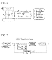
- FIG. 6 shows a schematic of the vibration control actuator system.
- FIG. 7 shows the schematic of a current loop of the LUICU.
- the five gains (g 1 through g 5 ) shown in the schematic are preferably optimized to achieve a desired performance.
Landscapes
- Engineering & Computer Science (AREA)
- Mechanical Engineering (AREA)
- General Engineering & Computer Science (AREA)
- Aviation & Aerospace Engineering (AREA)
- Physics & Mathematics (AREA)
- Electromagnetism (AREA)
- Vibration Prevention Devices (AREA)
- Apparatuses For Generation Of Mechanical Vibrations (AREA)
Abstract
Description
- The present invention relates to a method/system for controlling problematic vibrations. More particularly the invention relates to a method and system for controlling aircraft vehicle vibrations, particularly a method and system for canceling problematic rotary wing helicopter vibrations.
- Helicopter vibrations are particularly troublesome in that they can cause fatigue and wear on the equipment and occupants in the aircraft. In vehicles such as helicopters, vibrations are particularly problematic in that they can damage the actual structure and components that make up the vehicle in addition to the contents of the vehicle.
- There is a need for a system and method of accurately and economically canceling vehicle vibrations. There is a need for a system and method of accurately and economically controlling vibrations. There is a need for an economically feasible method of controlling vibrations in a helicopter so that the vibrations are efficiently cancelled and minimized. There is a need for a robust system of controlling vibrations in a helicopter so that the vibrations are efficiently cancelled and minimized. There is a need for an economic method/system for controlling problematic helicopter vibrations.
-
US-A-4922159 a vibration control actuator for controlling vibration of space deployed structures and seeks to remove any resonant component in the actuator.US-A-5920173 describes a vibration absorber.US-A-4497098 describes an instrument taken driver for providing a regulated beat or amplitude. - The invention includes a vibration canceling force generator for actively generating a vibration canceling force, as defined in
claim 1. The vibration canceling force generator includes a resonant actuator having a natural resonant frequency, and a resonant actuator electronic control system having a command input for receiving a command signal with the resonant actuator electronic control system providing an electrical drive current to the resonant actuator to drive the resonant actuator about the resonant frequency when commanded by a received command signal, and the resonant actuator has a feedback output with the feedback output fed back into the resonant actuator electronic control system wherein the resonant actuator electronic control system adjusts the electrical drive current based on the resonant actuator feedback output to generate the vibration canceling force. - The invention includes a method of making a vibration canceling force generator as defined in
claim 2. The method includes providing a resonant actuator having a natural resonant frequency, providing a resonant actuator electronic control system having a command input for receiving a command signal and a power amplifier for providing an electrical drive current to drive the resonant actuator, and connecting the resonant actuator with the resonant actuator electronic control system wherein the resonant actuator electronic control system electrical drive current drives the resonant actuator about the natural resonant frequency when commanded by a received command signal, with the resonant actuator feeding an electrical output back into the resonant actuator electronic control system wherein the resonant actuator electronic control system adjusts the electrical drive current based on the resonant actuator electrical output. - The invention includes a method of controlling vibrations as defined in
claim 3. The method includes providing a resonant actuator having a natural resonant frequency, providing a resonant actuator electronic control system for providing an electrical drive current to drive the resonant actuator, connecting the resonant actuator with the resonant actuator electronic control system, and driving the resonant actuator about the natural resonant frequency with the resonant actuator feeding an electrical output back into the resonant actuator electronic control system and adjusting the electrical drive current based on the resonant actuator electrical output. - The invention includes a vehicle vibration canceling system as defined in
claim 4. The vehicle vibration canceling system includes a resonant actuator having a natural resonant frequency. The vehicle vibration canceling system includes a resonant actuator electronic controller for providing an electrical drive current to the resonant actuator to drive the resonant actuator about the resonant frequency. The resonant actuator has a feedback electrical output with the feedback electrical output fed back into the resonant actuator electronic controller wherein said resonant actuator electronic controller adjusts said electrical drive current based on said resonant actuator feedback electrical output. - The invention includes a method of making a helicopter vibration canceling system as defined in
claim 5. The method includes providing a resonant actuator having a natural resonant frequency. The method includes providing a resonant actuator electronic control system for providing an electrical drive current to drive said resonant actuator. The method includes connecting the resonant actuator with the resonant actuator electronic control system wherein the resonant actuator electronic control system electrical drive current drives the resonant actuator about the natural resonant frequency with said resonant actuator feeding an electrical output back into the resonant actuator electronic control system wherein the resonant actuator electronic control system adjusts the electrical drive current based on the resonant actuator electrical output. - The invention includes a method of controlling helicopter vibrations as defined in claim 6. The method includes providing a resonant actuator having a natural resonant frequency. The method includes mounting the resonant actuator in a helicopter. The method includes providing a resonant actuator electronic control system for providing an electrical drive current to drive the resonant actuator. The method includes connecting the resonant actuator with the resonant actuator electronic control system. The method includes driving the resonant actuator about the natural resonant frequency with the resonant actuator feeding an electrical output back into the resonant actuator electronic control system and adjusting the electrical drive current based on the resonant actuator electrical output. Further features of the invention as defined in said independent method claim 6 are disclosed in dependent claims 7 to 13.
- It is to be understood that both the foregoing general description and the following detailed description are exemplary of the invention, and are intended to provide an overview or framework for understanding the nature and character of the invention as it is claimed. The accompanying drawings are included to provide a further understanding of the invention, and are incorporated in and constitute a part of this specification. The drawings illustrate various embodiments of the invention, and together with the description serve to explain the principles and operation of the invention.
-
-
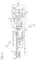
FIG. 1 shows methods and systems for controlling vibrations. -
FIG. 2A-D show resonant actuators for controlling vibrations. -
FIG. 3 shows methods and systems for controlling vibrations. -
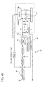
FIG. 4A-B show methods and systems for controlling vibrations. -
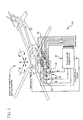
FIG. 5 shows methods and systems for controlling vibrations. -
FIG. 6 shows methods and systems for controlling vibrations. -
FIG. 7 shows methods and systems for controlling vibrations. -
FIG. 8 is a plot of Force (N) y-axis and Frequency (Hz) x-axis (Actuator Force for .75 volt command). -
FIG. 9 is a plot of Actuator Current (amps) y-axis and Frequency (Hz) x-axis (Actuator Current for .75 volt command). -
FIG. 10 is a plot of Actuator Voltage (volts) y-axis and Frequency (Hz) x-axis (Actuator Voltage for .75 volt command). -
FIG. 11 is a plot of Actuator Power (watts) y-axis and Frequency (Hz) x-axis (Actuator Power for .75 volt command). -
FIG. 12 is a plot of Resistive Power (watts) y-axis and Frequency (Hz) x-axis (Actuator Power for .75 volt command). -
FIG. 13 is a plot of Actuator Mass Displacement (mm) y-axis and Time (s) x-axis (Actuator Response to Step Input of .75 Volts). -
FIG. 14 is a plot of Actuator Mass Displacement (mm) y-axis and Time (s) x-axis (Actuator Response to 0.75 Volts Command at 22.1 Hz). -
FIG. 15 is a plot of Force (N) y-axis and Frequency (Hz) x-axis (Actuator Force for 0.75 volt command). -
FIG. 16 is a plot of Actuator Current (amps) y-axis and Frequency (Hz) x-axis (Actuator Current for 0.75 volt command). -
FIG. 17 is a plot of Actuator Voltage (volts) y-axis and Frequency (Hz) x-axis (Actuator Voltage for 0.75 volt command). - Additional features and advantages of the invention will be set forth in the detailed description which follows, and in part will be readily apparent to those skilled in the art from that description or recognized by practicing the invention as described herein, including the detailed description which follows, the claims, as well as the appended drawings.
- Reference will now be made in detail to the present preferred embodiments of the invention, examples of which are illustrated in the accompanying drawings.
- The invention comprises a vibration canceling force generator for actively generating a vibration canceling force. The vibration canceling force generator includes a resonant actuator having a natural resonant frequency, and a resonant actuator electronic control system with the resonant actuator electronic control system providing an electrical drive current to the resonant actuator to drive the resonant actuator about the resonant frequency when commanded. The resonant actuator has a feedback output with the feedback output fed back into the resonant actuator electronic control system wherein the resonant actuator electronic control system adjusts the electrical drive current based on the resonant actuator feedback output to generate the vibration canceling force.
- The invention includes a vibration canceling force generator for actively generating a vibration canceling force. The vibration canceling force generator includes a resonant actuator having a natural resonant frequency, and a resonant actuator electronic control system having a command input for receiving a command signal with the resonant actuator electronic control system providing an electrical drive current to the resonant actuator to drive the resonant actuator about the resonant frequency when commanded by a received command signal, and the resonant actuator has a feedback output with the feedback output fed back into the resonant actuator electronic control system wherein the resonant actuator electronic control system adjusts the electrical drive current based on the resonant actuator feedback output to generate the vibration canceling force. As shown in
FIG. 1-5 the vibration cancelingforce generator 20 actively generates avibration canceling force 22 which destructively interferes with and cancels an unwanted vibration force in astructure 50 that it is attached to. The vibration cancelingforce generator 20 preferably includes a linear voice coilresonant actuator 24 having a naturalresonant frequency 46. Preferably theresonant actuator 24 is an electromagnetically driven sprungmass 26 suspended onresilient metal flexures 32. As shown inFIG. 2A-D , the EM (ElectroMagnetic) drivenmass 26 is preferably suspended on a horizontal beam stack of multiple layers ofresilient metal flexures 32, which are preferably supported by two vertical side resilient metal flexures post plates, to provide a sprung mass that can be electromagnetically driven to oscillate at its natural resonant frequency. Preferably the resonant actuator sprung mass is driven by modulating an electromagnetic field so the sprung mass is attracted and repelled by the EM field at its resonant frequency. Preferably the resonant actuator sprung mass includes apermanent magnet 28 in alignment with anelectromagnetic coil 30, wherein a electrical drive current supplied to theEM coil 30 drives the sprung mass at resonance. The vibration cancelingforce generator 20 includes a resonant actuatorelectronic control system 34. Preferably the resonant actuatorelectronic control system 34 has acommand input 36 for receiving acommand signal 38 and the resonant actuator electronic control system includes apower amplifier 40 that produces the electrical drive current (i). The resonant actuatorelectronic control system 34 provides an electrical drive current 42 to theresonant actuator 24 to drive the resonant actuator about the resonant frequency when commanded by a receivedcommand signal 38, with the resonant actuator having afeedback output 44 fed back into the resonant actuator electronic control system wherein the resonant actuator electronic control system adjusts the electrical drive current (i) based on the resonantactuator feedback output 44 to generate thevibration canceling force 22. Preferably theresonant actuator 24 has a resonant actuator natural resonant frequency in a range of 15 to 40 Hz, more preferably in the range of 15-30 Hz, and most preferably in the range of 18 to 26 Hz. The vibration cancelingforce generator 20 is able to adapt to an aging of theresonant actuator 24 that alters the resonant actuator natural resonant frequency changes over an extended operation life time frame such as from the aging of the metal flexures and loosening of the metal flexure fasteners and fixtures over time, preferably with the utilization of the resonantactuator feedback output 44 to adjust the drive current to the resonant actuators aging natural resonant frequency so that the control system produced drive current can follow an aging change in the natural frequency over an extended period of time. Preferably theresonant actuator 24 has a damping level less than four percent of critical damping, more preferably a damping level less than two percent of critical damping. Preferably theresonant actuator 24 is a lightly damped resonant actuator. Preferably theresonant actuator 24 is a lightly damped resonant actuator with an effective damping ratio less than 0.5 (preferably with damping ratio = particular damping coefficient c / critical damping coefficient cr). The vibration cancelingforce generator 20 utilizes aresonant actuator 24 that has a lightly damped mass spring system highly resonant response, with the actuator driven at resonance because of its highly resonant response. Preferably thecommand signal 38 is an analog input voltage, which is received bycommand input 36 with the variable voltage input command signal commanding theelectronic control system 34 to produce aforce 22 to cancel the unwanted vibration force in the vibratingstructure 50. As shown inFIG. 4 , preferably the vibration canceling force generator includes electrical connector interfaces 52 for disengagably connecting theresonant actuator 24 to the resonant actuatorelectronic control system 34. Such an electrical connector interface preferably includes afeedback loop connector 52 and an electrical drivecurrent connector 52, with the connector interfaces 52 providing for interchanging ofactuators 24 with thecontrol systems 34 and the replacement and swapping ofresonant actuators 24. Preferably the resonantactuator feedback output 44 is an electrical output from the resonant actuator back into thecontrol system 34. In a preferred embodiment the actuator electrical output is directly fed from the actuator electrical output into the control system. In a preferred embodiment such as shown inFIG. 1 , no separate physical actuator motion sensor for producing the feedback output is utilized, with theelectrical feedback output 44 coming directly from the actuator and control system drive current. Preferably the resonant actuatorelectrical feedback output 44 is an electrical charge flow rate (i) through the resonant actuator, with the current (i_act) through the actuator fed back into the control system, with the actuator drive current (i) controlled and limited to a maximum operation value. Preferably the control system uses the current (i_act)feedback 44 in controlling the drive current (i) to drive the actuator at resonance and without the need of shape filtering. In an embodiment the resonantactuator feedback output 44 is an electrical potential difference through theresonant actuator 24, with the voltage (v_act) across the actuator fed back into the control system, with the voltage in the actuator controlled and limited to a maximum value corresponding to the rated voltage for the actuator for maximum operation displacement of the actuator at resonance. In an embodiment the resonantactuator feedback output 44 is the electrical charge flow rate (i_act) through the resonant actuator and the electrical potential difference (v_act) through the resonant actuator, with both the voltage and current fed back fromactuator 24. - The invention comprise a method of making a vibration canceling force generator. The method includes providing a resonant actuator having a natural resonant frequency, providing a resonant actuator electronic control system having a power amplifier for providing an electrical drive current to drive the resonant actuator, and connecting the resonant actuator with the resonant actuator electronic control system wherein the resonant actuator electronic control system electrical drive current drives the resonant actuator about the natural resonant frequency when commanded by a received command signal, with the resonant actuator feeding an electrical output back into the resonant actuator electronic control system wherein the resonant actuator electronic control system adjusts the electrical drive current based on the resonant actuator electrical output.
- The invention includes a method of making a vibration canceling
force generator 20. The method includes providing aresonant actuator 24 having a natural resonant frequency, providing a resonant actuatorelectronic control system 34 having a command input for receiving a command signal and a power amplifier for providing an electrical drive current (i) to drive the resonant actuator, and connecting the resonant actuator with the resonant actuator electronic control system wherein the resonant actuator electronic control system electrical drive current (i) drives the resonant actuator about the natural resonant frequency when commanded by a received command signal, with the resonant actuator feeding anelectrical output 44 back into the resonant actuator electronic control system wherein the resonant actuator electronic control system adjusts the electrical drive current (i) based on the resonant actuatorelectrical output 44. Providingresonant actuator 24 preferably includes providing an electromagnetically driven voice coil, preferably a sprungmass 26 driven by modulating a electromagnetic field produced by anEM coil 30 so the sprung mass is attracted and repelled by the EM field and the actuator resonates at its natural resonant frequency. Providing the resonant actuatorelectronic control system 34 preferably includes providing a resonant actuator electronic control system having acommand input 36 for receiving acommand signal 38 and apower amplifier 40 for providing an electrical drive current (i) to drive the resonant actuator about its resonant frequency. Preferably thecommand signal 38 is an analog input voltage, with the analog variable voltage input command signal commanding the control system to produce avibration canceling force 22 which destructively interferes with and cancels an unwanted vibration force in thestructure 50 that theactuator 24 is attached to. In a preferred embodiment such as shown inFIG. 1 , the actuatorelectrical output 44 is fed back directly into the control system, preferably with no separate physical actuator motion sensor needed for producing the feedback output. In an alternative embodiment, such as shown inFIG. 4 , the resonant actuatorelectrical output 44 includes an actuator sensor electrical output from anactuator sensor 54. Theactuator sensor 54 provides an actuator sensorelectrical output 44 relative to a physical motion characteristic of theactuator 24, such as a motion sensor measuring the motion of the movingmass 26. In an embodiment theactuator sensor 54 is an accelerometer mounted on the actuator driven sprung mass. In an embodiment theactuator sensor 54 is a velocity sensor measuring and sensing the velocity of the actuator driven sprung mass. In an embodiment theactuator sensor 54 is a displacement sensor measuring and sensing the displacement and position of the actuator driven sprung mass. Providing theresonant actuator 24, preferably includes providing a resonant actuator with a natural resonant frequency in the range of 15 to 40 Hz, more preferably 15-30Hz, and most preferably 18 to 26 Hz. Providing theresonant actuator 24, preferably includes providing a resonant actuator which has a damping level less than four percent of critical damping, more preferably less than two percent of critical damping. Preferably theactuator 24 is a lightly damped resonant actuator with an effective damping ratio less than 0.5 (damping ratio = particular damping coefficient c / critical damping coefficient cr). Preferably theactuator 24 has the highly resonant response of a lightly damped mass spring system. In an embodiment the method includes providing anelectrical connector interface 52 for disengagably connecting theresonant actuator 24 to the resonant actuatorelectronic control system 34, preferably including a feedbackoutput loop connectors 52, and electrical drivecurrent connectors 52, with the disengagement and engagement of the connector interfaces used to interchange ofactuators 24 with thecontrol system 34, and for replacing and swapping outactuators 24 driven by thecontrol system 34. Feeding back theelectrical feedback 44 preferably includes feeding back the electrical charge flow rate through the resonant actuator. The current (i) through theactuator 24 is fed back into the control system as (i_act) with the drive current controlled and limited to a maximum operation value, most preferably with no shape filtering used to drive theactuator 24. In an embodiment of the invention feeding back theelectrical feedback 44 preferably includes feeding back the electrical potential difference through the resonant actuator. The voltage across the actuator fed back into the control system as (v_act), with the voltage is controlled and limited to a maximum value corresponding to the rated voltage for theactuator 24 for maximum operation displacement of the actuator at resonance. In an embodiment feeding back theelectrical feedback 44 preferably includes feeding back both the electrical charge flow rate through the resonant actuator and the electrical potential difference through the resonant actuator, with both the voltage and current feedback from actuator. - The invention comprises a method of controlling vibrations. The method includes providing a resonant actuator having a natural resonant frequency, providing a resonant actuator electronic control system for providing an electrical drive current to drive the resonant actuator, connecting the resonant actuator with the resonant actuator electronic control system, and driving the resonant actuator about the natural resonant frequency with the resonant actuator feeding an electrical output back into the resonant actuator electronic control system and adjusting the electrical drive current based on the resonant actuator electrical output.
- The invention includes a method of controlling vibrations. The method includes providing a voice coil
resonant actuator 24 having a natural resonant frequency, preferably an electromagnetically driven sprung mass driven by modulating a electromagnetic field so the sprung mass is attracted and repelled by the EM field. The method includes providing a resonant actuatorelectronic control system 34 for providing an electrical drive current to drive the resonant actuator and connecting the resonant actuator with the resonant actuator electronic control system. The method includes driving the resonant actuator about the natural resonant frequency with the resonant actuator feeding an electrical output back into the resonant actuator electronic control system and adjusting the electrical drive current based on the resonant actuator electrical output. Preferably providing aresonant actuator 24 includes providing a resonant actuator with a natural resonant frequency in a range of 15 to 40 Hz, more preferably 15-30Hz, and most preferably 18 to 26 Hz. Preferably providing aresonant actuator 24 includes providing a resonant actuator with a damping level less than four percent of critical damping, more preferably less than two percent of critical damping. Preferably the lightly dampedresonant actuator 24 has an effective damping ratio less than 0.5 (damping ratio = particular damping coefficient c / critical damping coefficient cr), with the actuator having the highly resonant response of a lightly damped mass spring system. Preferably the method includes providing anelectrical connector interface 52 for disengagably connecting the resonant actuator to the resonant actuator electronic control system. Preferably the resonant actuatorelectrical output 44 is an electrical potential difference through the resonant actuator with the voltage across the actuator fed back into the control system, with voltage controlled/limited to a maximum value corresponding to the rated voltage for the actuator for maximum operation displacement of the actuator at resonance. Preferably the resonant actuatorelectrical output 44 is an electrical charge flow rate through the resonant actuator. Preferably the resonant actuator electrical output is an electrical charge flow rate through the resonant actuator and an electrical potential difference through the resonant actuator. In an embodiment the resonant actuator electrical output is an actuator sensor electrical output. - The invention includes a vehicle vibration canceling system. The vehicle vibration canceling system includes a resonant actuator having a natural resonant frequency. The vehicle vibration canceling system includes a resonant actuator electronic controller for providing an electrical drive current to the resonant actuator to drive the resonant actuator about the resonant frequency. The resonant actuator has a feedback electrical output with the feedback electrical output fed back into the resonant actuator electronic controller wherein said resonant actuator electronic controller adjusts said electrical drive current based on said resonant actuator feedback electrical output.
- The invention includes a vehicle vibration canceling system. The aircraft vehicle vibration canceling system includes a
resonant actuator 24 having a natural resonant frequency, and a resonant actuatorelectronic controller 34, with the resonant actuator electronic controller providing an electrical drive current to the resonant actuator to drive the resonant actuator about the resonant frequency, with the resonant actuator having a feedback electrical output, the feedback electrical output fed back into the resonant actuator electronic controller wherein the resonant actuator electronic controller adjusts the electrical drive current based on the resonant actuator feedback electrical output to produce a vibration canceling for 22 to cancel a vibration in thevehicle vibrating structure 50 to which it is attached. Preferably theresonant actuator 24 is an electromagnetically driven sprungmass 26 suspended onresilient metal flexures 32. As shown inFIG. 2A-D , the EM drivenmass 26 is preferably suspended on a horizontal beam stack of multiple layers ofresilient metal flexures 32, which are preferably supported by two vertical side resilient metal flexures post plates, to provide a sprung mass that can be electromagnetically driven to oscillate at its natural resonant frequency. Preferably the resonant actuator sprung mass is driven by modulating an electromagnetic field so the sprung mass is attracted and repelled by the EM field at its resonant frequency. Preferably the resonant actuator sprung mass includes apermanent magnet 28 in alignment with anelectromagnetic coil 30, wherein a electrical drive current supplied to theEM coil 30 drives the sprung mass at resonance. The vibration cancelingforce generator 20 includes a resonant actuatorelectronic control system 34. Preferably the resonant actuatorelectronic control system 34 has acommand input 36 for receiving acommand signal 38 and the resonant actuator electronic control system includes apower amplifier 40 that produces the electrical drive current (i). The resonant actuatorelectronic control system 34 provides an electrical drive current 42 to theresonant actuator 24 to drive the resonant actuator about the resonant frequency when commanded by a receivedcommand signal 38, with the resonant actuator having afeedback output 44 fed back into the resonant actuator electronic control system wherein the resonant actuator electronic control system adjusts the electrical drive current (i) based on the resonantactuator feedback output 44 to generate thevibration canceling force 22. Preferably theresonant actuator 24 has a resonant actuator natural resonant frequency in a range of 15 to 40 Hz, more preferably in the range of 15-30 Hz, and most preferably in the range of 18 to 26 Hz. The vibration cancelingforce generator 20 is able to adapt to an aging of theresonant actuator 24 that alters the resonant actuator natural resonant frequency changes over an extended operation life time frame such as from the aging of the metal flexures and loosening of the metal flexure fasteners and fixtures over time, preferably with the utilization of the resonantactuator feedback output 44 to adjust the drive current to the resonant actuators aging natural resonant frequency so that the control system produced drive current can follow an aging change in the natural frequency over an extended period of time. Preferably theresonant actuator 24 has a damping level less than four percent of critical damping, more preferably a damping level less than two percent of critical damping. Preferably theresonant actuator 24 is a lightly damped resonant actuator. Preferably theresonant actuator 24 is a lightly damped resonant actuator with an effective damping ratio less than 0.5 (preferably with damping ratio = particular damping coefficient c / critical damping coefficient cr). The vibration cancelingforce generator 20 utilizes aresonant actuator 24 that has a lightly damped mass spring system highly resonant response, with the actuator driven at resonance because of its highly resonant response. Preferably thecommand signal 38 is an analog input voltage, which is received bycommand input 36 with the variable voltage input command signal commanding theelectronic control system 34 to produce aforce 22 to cancel the unwanted vibration force in the vibratingstructure 50. As shown inFIG. 4 , preferably the vibration canceling force generator includes electrical connector interfaces 52 for disengagably connecting theresonant actuator 24 to the resonant actuatorelectronic control system 34. Such an electrical connector interface preferably includes afeedback loop connector 52 and an electrical drivecurrent connector 52, with the connector interfaces 52 providing for interchanging ofactuators 24 with thecontrol systems 34 and the replacement and swapping ofresonant actuators 24. Preferably the resonantactuator feedback output 44 is an electrical output from the resonant actuator back into thecontrol system 34. In a preferred embodiment the actuator electrical output is directly fed from the actuator electrical output into the control system. In a preferred embodiment such as shown inFIG. 1 , no separate physical actuator motion sensor for producing the feedback output is utilized, with theelectrical feedback output 44 coming directly from the actuator and control system drive current. Preferably the resonant actuatorelectrical feedback output 44 is an electrical charge flow rate (i) through the resonant actuator, with the current (i_act) through the actuator fed back into the control system, with the actuator drive current (i) controlled and limited to a maximum operation value. Preferably the control system uses the current (i_act)feedback 44 in controlling the drive current (i) to drive the actuator at resonance and without the need of shape filtering. In an embodiment the resonantactuator feedback output 44 is an electrical potential difference through theresonant actuator 24, with the voltage (v_act) across the actuator fed back into the control system, with the voltage in the actuator controlled and limited to a maximum value corresponding to the rated voltage for the actuator for maximum operation displacement of the actuator at resonance. In an embodiment the resonantactuator feedback output 44 is the electrical charge flow rate (i_act) through the resonant actuator and the electrical potential difference (v_act) through the resonant actuator, with both the voltage and current fed back fromactuator 24. - The invention includes a method of making a helicopter vibration canceling system. The method includes providing a resonant actuator having a natural resonant frequency. The method includes providing a resonant actuator electronic control system for providing an electrical drive current to drive said resonant actuator. The method includes connecting the resonant actuator with the resonant actuator electronic control system wherein the resonant actuator electronic control system electrical drive current drives the resonant actuator about the natural resonant frequency with said resonant actuator feeding an electrical output back into the resonant actuator electronic control system wherein the resonant actuator electronic control system adjusts the electrical drive current based on the resonant actuator electrical output.
- The invention includes a method of making a helicopter vibration canceling system for canceling vibrations generated in a helicopter. The method includes providing a
resonant actuator 24 having a natural resonant frequency, providing a resonant actuatorelectronic control system 34 for providing an electrical drive current to drive the resonant actuator, and connecting the resonant actuator with the resonant actuator electronic control system wherein the resonant actuator electronic control system electrical drive current drives the resonant actuator about the natural resonant frequency, with the resonant actuator feeding anelectrical output 44 back into the resonant actuator electronic control system wherein the resonant actuator electronic control system adjusts the electrical drive current based on the resonant actuator electrical output. Providingresonant actuator 24 preferably includes providing an electromagnetically driven voice coil, preferably a sprungmass 26 driven by modulating a electromagnetic field produced by anEM coil 30 so the sprung mass is attracted and repelled by the EM field and the actuator resonates at its natural resonant frequency. Providing the resonant actuatorelectronic control system 34 preferably includes providing a resonant actuator electronic control system having acommand input 36 for receiving acommand signal 38 and apower amplifier 40 for providing an electrical drive current (i) to drive the resonant actuator about its resonant frequency. Preferably thecommand signal 38 is an analog input voltage, with the analog variable voltage input command signal commanding the control system to produce avibration canceling force 22 which destructively interferes with and cancels an unwanted vibration force in thestructure 50 that theactuator 24 is attached to. In a preferred embodiment such as shown inFIG. 1 , the actuatorelectrical output 44 is fed back directly into the control system, preferably with no separate physical actuator motion sensor needed for producing the feedback output. In an alternative embodiment, such as shown inFIG. 4 , the resonant actuatorelectrical output 44 includes an actuator sensor electrical output from anactuator sensor 54. Theactuator sensor 54 provides an actuator sensorelectrical output 44 relative to a physical motion characteristic of theactuator 24, such as a motion sensor measuring the motion of the movingmass 26. In an embodiment theactuator sensor 54 is an accelerometer mounted on the actuator driven sprung mass. In an embodiment theactuator sensor 54 is a velocity sensor measuring and sensing the velocity of the actuator driven sprung mass. In an embodiment theactuator sensor 54 is a displacement sensor measuring and sensing the displacement and position of the actuator driven sprung mass. Providing theresonant actuator 24, preferably includes providing a resonant actuator with a natural resonant frequency in the range of 15 to 40 Hz, more preferably 15-30Hz, and most preferably 18 to 26 Hz. Providing theresonant actuator 24, preferably includes providing a resonant actuator which has a damping level less than four percent of critical damping, more preferably less than two percent of critical damping. Preferably theactuator 24 is a lightly damped resonant actuator with an effective damping ratio less than 0.5 (damping ratio = particular damping coefficient c / critical damping coefficient cr). Preferably theactuator 24 has the highly resonant response of a lightly damped mass spring system. In an embodiment the method includes providing anelectrical connector interface 52 for disengagably connecting theresonant actuator 24 to the resonant actuatorelectronic control system 34, preferably including a feedbackoutput loop connectors 52, and electrical drivecurrent connectors 52, with the disengagement and engagement of the connector interfaces used to interchange ofactuators 24 with thecontrol system 34, and for replacing and swapping outactuators 24 driven by thecontrol system 34. Feeding back theelectrical feedback 44 preferably includes feeding back the electrical charge flow rate through the resonant actuator. The current (i) through theactuator 24 is fed back into the control system as (i_act) with the drive current controlled and limited to a maximum operation value, most preferably with no shape filtering used to drive theactuator 24. In an embodiment of the invention feeding back theelectrical feedback 44 preferably includes feeding back the electrical potential difference through the resonant actuator. The voltage across the actuator fed back into the control system as (v_act), with the voltage is controlled and limited to a maximum value corresponding to the rated voltage for theactuator 24 for maximum operation displacement of the actuator at resonance. In an embodiment feeding back theelectrical feedback 44 preferably includes feeding back both the electrical charge flow rate through the resonant actuator and the electrical potential difference through the resonant actuator, with both the voltage and current feedback from actuator. - The invention includes a method of controlling helicopter vibrations. The method includes providing a resonant actuator having a natural resonant frequency. The method includes mounting the resonant actuator in a helicopter. The method includes providing a resonant actuator electronic control system for providing an electrical drive current to drive the resonant actuator. The method includes connecting the resonant actuator with the resonant actuator electronic control system. The method includes driving the resonant actuator about the natural resonant frequency with the resonant actuator feeding an electrical output back into the resonant actuator electronic control system and adjusting the electrical drive current based on the resonant actuator electrical output.
- The invention includes a method of controlling helicopter vibrations. The method includes providing a
resonant actuator 24 having a natural resonant frequency, mounting the resonant actuator in a helicopter to a vibratingstructure 50 of the helicopter, providing a resonant actuatorelectronic control system 34 for providing an electrical drive current to drive the resonant actuator, connecting the resonant actuator with the resonant actuator electronic control system, and driving the resonant actuator about the natural resonant frequency with the resonant actuator feeding an electrical output back into the resonant actuator electronic control system and adjusting the electrical drive current based on the resonant actuator electrical output. The method includes driving the resonant actuator about the natural resonant frequency with the resonant actuator feeding an electrical output back into the resonant actuator electronic control system and adjusting the electrical drive current based on the resonant actuator electrical output. Preferably providing aresonant actuator 24 includes providing a resonant actuator with a natural resonant frequency in a range of 15 to 40 Hz, more preferably 15-30Hz, and most preferably 18 to 26 Hz. Preferably providing aresonant actuator 24 includes providing a resonant actuator with a damping level less than four percent of critical damping, more preferably less than two percent of critical damping. Preferably the lightly dampedresonant actuator 24 has an effective damping ratio less than 0.5 (damping ratio = particular damping coefficient c / critical damping coefficient cr), with the actuator having the highly resonant response of a lightly damped mass spring system. Preferably the method includes providing anelectrical connector interface 52 for disengagably connecting the resonant actuator to the resonant actuator electronic control system. Preferably the resonant actuatorelectrical output 44 is an electrical potential difference through the resonant actuator with the voltage across the actuator fed back into the control system, with voltage controlled/limited to a maximum value corresponding to the rated voltage for the actuator for maximum operation displacement of the actuator at resonance. Preferably the resonant actuatorelectrical output 44 is an electrical charge flow rate through the resonant actuator. Preferably the resonant actuator electrical output is an electrical charge flow rate through the resonant actuator and an electrical potential difference through the resonant actuator. In an embodiment the resonant actuator electrical output is an actuator sensor electrical output. - The invention utilizes tuning of the current loop of the amplifier to provide force shaping without using a shaping filter, with such tuning limiting the maximum current and power delivered to the actuator at frequencies away from resonance and, keeps the moving mass displacements below fatigue limits at resonance. The amplifier behaves like a voltage controlled amplifier close to the resonance frequency and a current controlled amplifier away from resonance. Since the actuator voltage is proportional to flexure displacement near resonance, limiting the actuator voltage near resonance protects the actuator from being overdriven. Preferably the magnitude of the trans-conductance dip of the amplifier is tuned to limit displacement at resonance and the pass-band gain of the amplifier inorder to limit the current/power away from the resonance frequency. The invention allows the system to adapt to changes in the resonance frequency. With the invention no data is required from the installed actuators and no shaping filters are required in the system. With the invention the actuators can be changed, swapped, repaired, and/or replaced without making any changes and/or adjustments to the electronic control system.
-
FIG. 6 shows a schematic of the vibration control actuator system. The actuator system can be modeled using the following equations:


FIG. 7 shows the schematic of a current loop of the LUICU. The five gains (g1 through g5) shown in the schematic are preferably optimized to achieve a desired performance. Preferably with loop optimization, there are five parameters for optimization in the control scheme: - Input gain g1
- Compensator gains g2, g3, g4
- Feedback loop gain g5
- Preferably with loop optimization, there are two considerations:
- 1) The system should not exceed the physical limits;
- 2) The system should have sufficient stability margins.
- ■ Imax = 5amps, Pmax = 100 watts and Freq = 3000 N
- ■ w1 = 300, w2 = 1 and w3 = 6
- ■ ω1 = 10 Hz, ωn = 21.6 Hz
- It will be apparent to those skilled in the art that various modifications and variations can be made to the present invention without departing from the scope of the invention. Thus, it is intended that the present invention cover the modifications and variations of this invention provided they come within the scope of the appended claims.


where Imax and Pmax are the maximum allowed current and power respectively. The Freq is the desired force.
For simplicity and demonstration purposes, two gains are optimized, g 1 and g 5, with the following values used:
| Cost Function | g 1 | g 5 |
| Φ1 | 0.95555 | 0.10654 |
| Φ2 | 1.0396 | 0.2585 |
| Φ3 | 0.96887 | 0.13062 |
g1 = 0.295, g2 =50, g3 = 2*pi*2.4, g4 = 2*pi*354, g5 =0.1245 ; the testing was done for an actuator mass of 14.2 and resonance of 21.72 ; the optimization was done for mass of 13 ; the test demonstrated that the system performance was within specs. It is noted that the mass estimation is important to limit the force, since we tuned the resonant acceleration and not the force.
Claims (13)
- A vibration canceling force generator (20) for actively generating a vibration canceling force (22), said vibration canceling force generator (20) characterised in that the generator (20) comprises:a resonant actuator (24) having a natural resonant frequency (46), and a resonant actuator electronic control system (34) having a command input (36) for receiving a command signal (38), said resonant actuator electronic control system (34) providing an electrical drive current (42) to said resonant actuator to drive said resonant actuator (24) about said resonant frequency (46) when commanded by a received command signal (38), said resonant actuator (24) having a feedback output (44), said feedback output (44) fed back into said resonant actuator electronic control system (34) wherein said resonant actuator electronic control system (34) adjusts said electrical drive current (42) based on said resonant actuator feedback output (44) to generate said vibration canceling force (22).
- A method of making a vibration canceling force generator (20), characterised in that said method comprising the steps of: providing a resonant actuator (24) having a natural resonant frequency, providing a resonant actuator electronic control system (34) having a command input for receiving a command signal (38) and a power amplifier (40) for providing an electrical drive current to drive said resonant actuator (24), connecting said resonant actuator with said resonant actuator electronic control system wherein said resonant actuator electronic control system electrical drive current drives said resonant actuator about said natural resonant frequency when commanded by a received command signal, with said resonant actuator feeding an electrical output back into said resonant actuator electronic control system wherein said resonant actuator electronic control system adjusts said electrical drive current based on said resonant actuator electrical output.
- A method of controlling vibrations, characterised in that said method comprising the steps of: providing a resonant actuator (24) having a natural resonant frequency, providing a resonant actuator electronic control system (34) for providing an electrical drive current (42) to drive said resonant actuator (24), connecting said resonant actuator (24) with said resonant actuator electronic control system (34), driving said resonant actuator (24) about said natural resonant frequency (46) with said resonant actuator (24) feeding an electrical output (44) back into said resonant actuator electronic control system (34) and adjusting said electrical drive current (42) based on said resonant actuator electrical output (44).
- A vehicle vibration canceling system, characterised in that said vehicle vibration canceling system comprises: a resonant actuator (24) having a natural resonant frequency (46), and a resonant actuator electronic controller (34), said resonant actuator electronic controller (34) providing an electrical drive current (42) to said resonant actuator (24) to drive said resonant actuator (24) about said resonant frequency (46), said resonant actuator (24) having a feedback electrical output (44), said feedback electrical output (44) fed back into said resonant actuator electronic controller (34) wherein said resonant actuator electronic controller (34) adjusts said electrical drive current (42) based on said resonant actuator feedback electrical output (44).
- A method of making a helicopter vibration canceling system, characterised in that said method comprises the steps of: providing a resonant actuator (24) having a natural resonant frequency (46),
providing a resonant actuator electronic control system (34) for providing an electrical drive current (42) to drive said resonant actuator (24), connecting said resonant actuator (24) with said resonant actuator electronic control system (34) wherein said resonant actuator electronic control system electrical drive current (42) drives said resonant actuator about said natural resonant frequency (46), with said resonant actuator (24) feeding an electrical output (44) back into said resonant actuator electronic control system (34) wherein said resonant actuator electronic control system (34) adjusts said electrical drive current (42) based on said resonant actuator electrical output (44). - A method of controlling helicopter vibrations, characterised in that said method comprises the steps of: providing a resonant actuator (24) having a natural resonant frequency (46), mounting said resonant actuator (24) in a helicopter, providing a resonant actuator electronic control system (34) for providing an electrical drive current (42) to drive said resonant actuator (24), connecting said resonant actuator (24) with said resonant actuator electronic control system (34), driving said resonant actuator (24) about said natural resonant frequency with said resonant actuator (24) feeding an electrical output (44) back into said resonant actuator electronic control system (34) and adjusting said electrical drive current (42) based on said resonant actuator electrical output (44).
- A method as claimed in claim 6 wherein providing a resonant actuator (24) includes providing a resonant actuator (24) with a natural resonant frequency (46) in a range of 15 to 40 Hz.
- A method as claimed in claim 6 wherein said resonant actuator (24) has a damping level less than four percent of critical damping.
- A method as claimed in claim 6 wherein said method includes providing an electrical connector interface (52) for disengagably connecting said resonant actuator (24) to said resonant actuator electronic control system (34).
- A method as claimed in claim 6, wherein said resonant actuator electrical output (44) is an electrical potential difference through said resonant actuator (24).
- A method as claimed in claim 6, wherein said resonant actuator electrical output (44) is an electrical charge flow rate through said resonant actuator (24).
- A method as claimed in claim 6, wherein said resonant actuator electrical output (44) is an electrical charge flow rate through said resonant actuator (24) and an electrical potential difference through said resonant actuator (24).
- A method as claimed in claim 6, wherein said resonant actuator electrical output (44) is an actuator sensor electrical output.
Applications Claiming Priority (2)
| Application Number | Priority Date | Filing Date | Title |
|---|---|---|---|
| US57864504P | 2004-06-10 | 2004-06-10 | |
| PCT/US2005/020580 WO2006083295A1 (en) | 2004-06-10 | 2005-06-10 | A method and system for controlling helicopter vibrations |
Publications (2)
| Publication Number | Publication Date |
|---|---|
| EP1766261A1 EP1766261A1 (en) | 2007-03-28 |
| EP1766261B1 true EP1766261B1 (en) | 2012-02-08 |
Family
ID=36591328
Family Applications (1)
| Application Number | Title | Priority Date | Filing Date |
|---|---|---|---|
| EP05856808A Ceased EP1766261B1 (en) | 2004-06-10 | 2005-06-10 | A method and system for controlling helicopter vibrations |
Country Status (4)
| Country | Link |
|---|---|
| US (3) | US7370829B2 (en) |
| EP (1) | EP1766261B1 (en) |
| CN (1) | CN100535473C (en) |
| WO (1) | WO2006083295A1 (en) |
Families Citing this family (33)
| Publication number | Priority date | Publication date | Assignee | Title |
|---|---|---|---|---|
| CN100535473C (en) * | 2004-06-10 | 2009-09-02 | 洛德公司 | Method and system for controlling helicopter vibrations |
| US8162606B2 (en) | 2004-08-30 | 2012-04-24 | Lord Corporation | Helicopter hub mounted vibration control and circular force generation systems for canceling vibrations |
| US7722322B2 (en) | 2004-08-30 | 2010-05-25 | Lord Corporation | Computer system and program product for controlling vibrations |
| CN101022994B (en) | 2004-08-30 | 2012-07-04 | 洛德公司 | Helicopter vibration control system and rotary force generator for canceling vibrations |
| US8267652B2 (en) | 2004-08-30 | 2012-09-18 | Lord Corporation | Helicopter hub mounted vibration control and circular force generation systems for canceling vibrations |
| KR101140925B1 (en) * | 2006-05-08 | 2012-05-03 | 신꼬오덴끼가부시끼가이샤 | Damper for automobiles for reducing vibration of automobile body |
| CA2665700C (en) * | 2006-10-12 | 2013-11-19 | Bell Helicopter Textron Inc. | Vibration-attenuating hard-mounted pylon |
| WO2009055007A2 (en) * | 2007-10-25 | 2009-04-30 | Lord Corporation | Distributed active vibration control systems and rotary wing aircraft with suppressed vibrations |
| EP2279118B1 (en) * | 2008-04-07 | 2013-12-25 | Lord Corporation | Helicopter hub mounted vibration control and circular force generation systems for canceling vibrations |
| CA2722626A1 (en) | 2008-04-07 | 2009-10-15 | Lord Corporation | Helicopter vibration control system and circular force generation system for canceling vibrations |
| DE102008025298B4 (en) * | 2008-05-27 | 2010-12-16 | Deutsches Zentrum für Luft- und Raumfahrt e.V. | Method and device for active damping of vertical vibrations in a helicopter with attached external load |
| EP2350491B1 (en) * | 2008-11-04 | 2016-05-04 | LORD Corporation | Resonant inertial force generator having stable natural frequency |
| CA2752701C (en) * | 2009-02-27 | 2016-04-26 | Bell Helicopter Textron Inc. | System and method for vibration control in a rotorcraft using an adaptive reference model algorithm |
| US8129870B1 (en) * | 2009-08-04 | 2012-03-06 | Pusl Kenneth E | Asymmetric folded spring flexure suspension system for reciprocating devices |
| JP5022457B2 (en) * | 2010-02-17 | 2012-09-12 | 三菱重工業株式会社 | Vibration reducing apparatus and vibration reducing method |
| US8190307B2 (en) * | 2010-08-23 | 2012-05-29 | King Fahd University Of Petroleum & Minerals | Control optimization method for helicopters carrying suspended loads |
| EP2670661B1 (en) | 2011-02-04 | 2015-01-14 | Lord Corporation | Rotary wing aircraft vibration control system with resonant inertial actuators |
| JP5863528B2 (en) * | 2012-03-23 | 2016-02-16 | 三菱重工業株式会社 | Vibration reduction device |
| CN102890464B (en) * | 2012-09-29 | 2014-11-12 | 西安电子科技大学 | Method for controlling lifting and vibrating motions of large-span cantilever truss |
| US9274602B2 (en) * | 2012-10-30 | 2016-03-01 | Texas Instruments Incorporated | Haptic actuator controller |
| CN103884285B (en) * | 2012-12-21 | 2017-08-29 | 中国直升机设计研究所 | A kind of method of testing of dynamic component displacement |
| JP6144090B2 (en) * | 2013-04-08 | 2017-06-07 | 樋口 俊郎 | Electromagnetic actuator |
| US9344022B2 (en) | 2013-09-11 | 2016-05-17 | Qualcomm Incorporated | Circuits and methods for driving resonant actuators |
| EP2857313B1 (en) * | 2013-10-03 | 2015-12-23 | AGUSTAWESTLAND S.p.A. | Hover aircraft rotor comprising a vibration damping device |
| US9689453B2 (en) * | 2014-02-06 | 2017-06-27 | Asm Technology Singapore Pte. Ltd. | Active vibration absorber |
| US9146557B1 (en) * | 2014-04-23 | 2015-09-29 | King Fahd University Of Petroleum And Minerals | Adaptive control method for unmanned vehicle with slung load |
| WO2016048442A1 (en) * | 2014-09-26 | 2016-03-31 | Sikorsky Aircraft Corporation | Damage adaptive vibration control |
| JP6412409B2 (en) * | 2014-11-07 | 2018-10-24 | Kyb株式会社 | Suspension device and suspension control device |
| CN105257750B (en) * | 2015-11-19 | 2018-10-09 | 西安空间无线电技术研究所 | A kind of multi-modal Electromagnet absorber |
| DE102016223864A1 (en) * | 2016-11-30 | 2018-05-30 | Audi Ag | An active vibration absorption system for absorbing a vibration of a vibrating element, and a motor vehicle having the active vibration absorption system and a method for operating the active vibration absorption system |
| FR3064037B1 (en) | 2017-03-16 | 2019-03-22 | Airbus Helicopters | DEVICE FOR ANTI-VIBRATION SUSPENSION OF A MECHANICAL ELEMENT, AND AIRCRAFT. |
| US10648529B2 (en) | 2017-11-21 | 2020-05-12 | Bell Helicopter Textron Inc. | Hydraulic vibration control |
| US11118906B2 (en) * | 2019-03-29 | 2021-09-14 | Property Management Co., Ltd. | Oscillator circuit including oscillator |
Family Cites Families (40)
| Publication number | Priority date | Publication date | Assignee | Title |
|---|---|---|---|---|
| US4479098A (en) | 1981-07-06 | 1984-10-23 | Watson Industries, Inc. | Circuit for tracking and maintaining drive of actuator/mass at resonance |
| US4497098A (en) | 1982-09-07 | 1985-02-05 | Hitco | Fill yarn removal apparatus |
| US4483425A (en) | 1982-09-09 | 1984-11-20 | North American Philips Corporation | Vibration control system |
| US4819182A (en) * | 1985-06-21 | 1989-04-04 | Westland Plc | Method and apparatus for reducing vibration of a helicopter fuselage |
| US4808955A (en) | 1987-10-05 | 1989-02-28 | Bei Electronics, Inc. | Moving coil linear actuator with interleaved magnetic circuits |
| US4922159A (en) * | 1988-05-09 | 1990-05-01 | Harris Corporation | Linear precision actuator with accelerometer feedback |
| US5231336A (en) | 1992-01-03 | 1993-07-27 | Harman International Industries, Inc. | Actuator for active vibration control |
| US5219037A (en) * | 1992-01-21 | 1993-06-15 | General Motors Corporation | Component mount assembly providing active control of vehicle vibration |
| US5278913A (en) | 1992-07-28 | 1994-01-11 | Nelson Industries, Inc. | Active acoustic attenuation system with power limiting |
| US5345206A (en) | 1992-11-24 | 1994-09-06 | Bei Electronics, Inc. | Moving coil actuator utilizing flux-focused interleaved magnetic circuit |
| DE4301845C1 (en) * | 1993-01-23 | 1994-03-31 | Freudenberg Carl Fa | Active vibration damper for oscillating machine part - includes inertial, reciprocatable mass carrying plate via coupling spring and fixable at machine part |
| US5332061A (en) * | 1993-03-12 | 1994-07-26 | General Motors Corporation | Active vibration control system for attenuating engine generated vibrations in a vehicle |
| US5456341A (en) | 1993-04-23 | 1995-10-10 | Moog Inc. | Method and apparatus for actively adjusting and controlling a resonant mass-spring system |
| US5682069A (en) | 1994-08-30 | 1997-10-28 | Harris Corporation | Concentrically mounted vibration attenuator and method |
| US5526292A (en) | 1994-11-30 | 1996-06-11 | Lord Corporation | Broadband noise and vibration reduction |
| FR2730288B1 (en) * | 1995-02-03 | 1997-04-18 | Mesure Et Inf Mei | ACTIVE CONTROLLED VIBRATION REDUCTION DEVICES CONSISTING OF MOBILE MASSES EXCITED BY ELECTRO MAGNETS ACCORDING TO 2 OR 3 AXES |
| US5710822A (en) | 1995-11-07 | 1998-01-20 | Digisonix, Inc. | Frequency selective active adaptive control system |
| US5920173A (en) | 1995-11-15 | 1999-07-06 | Applied Power Inc. | Feedback enhanced adaptively tuned vibration absorber |
| GB9523651D0 (en) * | 1995-11-18 | 1996-01-17 | Gkn Westland Helicopters Ltd | Helicopter and method for reucing vibration of a helicopter fuselage |
| FR2749901B1 (en) | 1996-06-12 | 2000-12-08 | Eurocopter France | DEVICE FOR REDUCING THE VIBRATION GENERATED BY A LIFT ROTOR OF A TURNED AIRCRAFT |
| US5883478A (en) | 1996-10-11 | 1999-03-16 | Ts Engineering Inc. | Apparatus and method for controlling vibrating equipment |
| US6009985A (en) * | 1997-02-10 | 2000-01-04 | Lord Corporation | Efficient multi-directional active vibration absorber assembly |
| US6094601A (en) | 1997-10-01 | 2000-07-25 | Digisonix, Inc. | Adaptive control system with efficiently constrained adaptation |
| US5954169A (en) * | 1997-10-24 | 1999-09-21 | Lord Corporation | Adaptive tuned vibration absorber, system utilizing same and method of controlling vibration therewith |
| JP3564974B2 (en) | 1997-11-07 | 2004-09-15 | 東海ゴム工業株式会社 | Adaptive control method for periodic signals |
| FR2770825B1 (en) | 1997-11-13 | 1999-12-31 | Eurocopter France | DEVICE FOR REDUCING VIBRATION IN THE CABIN OF A TURNING AIRCRAFT, ESPECIALLY A HELICOPTER |
| US5896076A (en) | 1997-12-29 | 1999-04-20 | Motran Ind Inc | Force actuator with dual magnetic operation |
| US6006875A (en) | 1998-03-31 | 1999-12-28 | Motran Industries Inc | Electrically-tunable vibration absorbers |
| US6059274A (en) | 1998-05-04 | 2000-05-09 | Gte Internetworking Incorporated | Vibration reduction system using impedance regulated active mounts and method for reducing vibration |
| DE69939796D1 (en) | 1998-07-16 | 2008-12-11 | Matsushita Electric Industrial Co Ltd | Noise control arrangement |
| FR2784350B1 (en) | 1998-10-12 | 2000-12-08 | Eurocopter France | DEVICE FOR REDUCING VIBRATIONS GENERATED ON THE STRUCTURE OF A TURNED AIRCRAFT |
| WO2000049309A2 (en) | 1999-02-22 | 2000-08-24 | Cooper Tire & Rubber Company | Apparatus for vibrations attenuation using electronic and electromagnetic actuation |
| TW476679B (en) * | 1999-05-26 | 2002-02-21 | Shinko Electric Co Ltd | Device for suppressing the vibration of a steel plate |
| US6355994B1 (en) | 1999-11-05 | 2002-03-12 | Multibeam Systems, Inc. | Precision stage |
| US6467723B1 (en) | 2000-10-10 | 2002-10-22 | Lord Corporation | Active vibration control system for helicopter with improved actustor placement |
| US6639496B1 (en) | 2001-04-25 | 2003-10-28 | Van Namen Frederik T. | Bistable long-stroke electro-magnetic mechanical actuator |
| US6512435B2 (en) | 2001-04-25 | 2003-01-28 | Charles Willard | Bistable electro-magnetic mechanical actuator |
| US7288861B1 (en) * | 2004-03-06 | 2007-10-30 | Motran Industries Inc. | Inertial actuator with multiple flexure stacks |
| CN100535473C (en) * | 2004-06-10 | 2009-09-02 | 洛德公司 | Method and system for controlling helicopter vibrations |
| US7550880B1 (en) * | 2006-04-12 | 2009-06-23 | Motran Industries Inc | Folded spring flexure suspension for linearly actuated devices |
-
2005
- 2005-06-10 CN CNB2005800191027A patent/CN100535473C/en not_active Expired - Fee Related
- 2005-06-10 EP EP05856808A patent/EP1766261B1/en not_active Ceased
- 2005-06-10 WO PCT/US2005/020580 patent/WO2006083295A1/en not_active Ceased
- 2005-06-10 US US11/149,514 patent/US7370829B2/en not_active Expired - Lifetime
-
2007
- 2007-11-19 US US11/942,381 patent/US7686246B2/en not_active Expired - Lifetime
-
2009
- 2009-12-17 US US12/640,149 patent/US8272592B2/en not_active Expired - Lifetime
Also Published As
| Publication number | Publication date |
|---|---|
| US20080179451A1 (en) | 2008-07-31 |
| CN100535473C (en) | 2009-09-02 |
| US20100090054A1 (en) | 2010-04-15 |
| US20060054738A1 (en) | 2006-03-16 |
| US8272592B2 (en) | 2012-09-25 |
| US7686246B2 (en) | 2010-03-30 |
| EP1766261A1 (en) | 2007-03-28 |
| CN1973148A (en) | 2007-05-30 |
| WO2006083295A1 (en) | 2006-08-10 |
| US7370829B2 (en) | 2008-05-13 |
Similar Documents
| Publication | Publication Date | Title |
|---|---|---|
| US8272592B2 (en) | Method and system for controlling helicopter vibrations | |
| US6193206B1 (en) | Active vibration isolator | |
| EP1866555B1 (en) | Vibration isolation | |
| KR102371302B1 (en) | Operating units for devices, in particular vehicle components | |
| US7107127B2 (en) | Computationally efficient means for optimal control with control constraints | |
| EP2620670A1 (en) | Active damping device, vehicle, method for controlling active damping device | |
| KR101656841B1 (en) | An antivibration suspension device for a mechanical element, and an aircraft | |
| KR101120563B1 (en) | A method of tuning a vibration absorber | |
| Hansson et al. | Vibration suppression of railway car body with piezoelectric elements (A study by using a scale model) | |
| EP2541094B1 (en) | Helicopter and vibration reduction method | |
| US20240135790A1 (en) | Haptic output device and method for providing haptic output | |
| JP2021189229A (en) | Simulator device | |
| Pagliarulo et al. | Tunable magnetostrictive dynamic vibration absorber | |
| KR20070022703A (en) | Method and system to control helicopter vibration | |
| WO2005059397A1 (en) | Inertial actuator | |
| DE102017200300A1 (en) | Active damping device for reducing a body vibration of a component and motor vehicle | |
| US11203417B2 (en) | Rotorcraft fitted with an antivibration system, and a method of adjusting such an antivibration system | |
| Şahin et al. | Design of a Modified linear quadratic regulator for vibration control of suspension systems of military and civiL vehicle | |
| OKAMURA et al. | Multi-Degree-of-Freedom Active Seat Suspension for Ultra-Compact Mobility (Analytical Consideration on Control of Two-Degree-of-Freedom Vibration Using Linear Actuators) | |
| JP2010002033A (en) | Vibration reducing device and vibration reducing method | |
| EP3106710B1 (en) | Vibration absorber device | |
| DE102017001960A1 (en) | Method for controlling dual magnetic effects | |
| WO2020002381A1 (en) | Micromechanical component and method for operating a micromechanical component | |
| Sapinski | Real-time controllers for a MR damper in a quarter car suspension-Results of laboratory tests | |
| Lau | Active vibration control at machinery feet |
Legal Events
| Date | Code | Title | Description |
|---|---|---|---|
| PUAI | Public reference made under article 153(3) epc to a published international application that has entered the european phase |
Free format text: ORIGINAL CODE: 0009012 |
|
| 17P | Request for examination filed |
Effective date: 20061122 |
|
| AK | Designated contracting states |
Kind code of ref document: A1 Designated state(s): FR IT |
|
| DAX | Request for extension of the european patent (deleted) | ||
| RBV | Designated contracting states (corrected) |
Designated state(s): FR IT |
|
| 17Q | First examination report despatched |
Effective date: 20090626 |
|
| GRAP | Despatch of communication of intention to grant a patent |
Free format text: ORIGINAL CODE: EPIDOSNIGR1 |
|
| GRAS | Grant fee paid |
Free format text: ORIGINAL CODE: EPIDOSNIGR3 |
|
| GRAA | (expected) grant |
Free format text: ORIGINAL CODE: 0009210 |
|
| AK | Designated contracting states |
Kind code of ref document: B1 Designated state(s): FR IT |
|
| PLBE | No opposition filed within time limit |
Free format text: ORIGINAL CODE: 0009261 |
|
| STAA | Information on the status of an ep patent application or granted ep patent |
Free format text: STATUS: NO OPPOSITION FILED WITHIN TIME LIMIT |
|
| 26N | No opposition filed |
Effective date: 20121109 |
|
| PGFP | Annual fee paid to national office [announced via postgrant information from national office to epo] |
Ref country code: IT Payment date: 20140623 Year of fee payment: 10 |
|
| PG25 | Lapsed in a contracting state [announced via postgrant information from national office to epo] |
Ref country code: IT Free format text: LAPSE BECAUSE OF NON-PAYMENT OF DUE FEES Effective date: 20150610 |
|
| REG | Reference to a national code |
Ref country code: FR Ref legal event code: PLFP Year of fee payment: 12 |
|
| REG | Reference to a national code |
Ref country code: FR Ref legal event code: PLFP Year of fee payment: 13 |
|
| REG | Reference to a national code |
Ref country code: FR Ref legal event code: PLFP Year of fee payment: 14 |
|
| P01 | Opt-out of the competence of the unified patent court (upc) registered |
Effective date: 20230524 |
|
| PGFP | Annual fee paid to national office [announced via postgrant information from national office to epo] |
Ref country code: FR Payment date: 20230626 Year of fee payment: 19 |
|
| PG25 | Lapsed in a contracting state [announced via postgrant information from national office to epo] |
Ref country code: FR Free format text: LAPSE BECAUSE OF NON-PAYMENT OF DUE FEES Effective date: 20240630 |