EP1765670B2 - In-flight refueling system and method for facilitating emergency separation of in-flight refueling system components - Google Patents
In-flight refueling system and method for facilitating emergency separation of in-flight refueling system components Download PDFInfo
- Publication number
- EP1765670B2 EP1765670B2 EP05856875.9A EP05856875A EP1765670B2 EP 1765670 B2 EP1765670 B2 EP 1765670B2 EP 05856875 A EP05856875 A EP 05856875A EP 1765670 B2 EP1765670 B2 EP 1765670B2
- Authority
- EP
- European Patent Office
- Prior art keywords
- drogue
- elongate hose
- fuse device
- aircraft
- hose
- Prior art date
- Legal status (The legal status is an assumption and is not a legal conclusion. Google has not performed a legal analysis and makes no representation as to the accuracy of the status listed.)
- Active
Links
- 238000000034 method Methods 0.000 title claims abstract description 25
- 238000000926 separation method Methods 0.000 title claims abstract description 14
- 239000012530 fluid Substances 0.000 claims abstract description 12
- 238000004891 communication Methods 0.000 claims abstract description 11
- 239000000446 fuel Substances 0.000 claims description 23
- 230000000903 blocking effect Effects 0.000 claims description 4
- 239000000523 sample Substances 0.000 abstract description 47
- 230000007246 mechanism Effects 0.000 description 17
- 239000000463 material Substances 0.000 description 4
- 230000007257 malfunction Effects 0.000 description 3
- 239000002131 composite material Substances 0.000 description 2
- 239000002184 metal Substances 0.000 description 2
- 229910001092 metal group alloy Inorganic materials 0.000 description 2
- 229920000642 polymer Polymers 0.000 description 2
- 230000008439 repair process Effects 0.000 description 2
- 239000000853 adhesive Substances 0.000 description 1
- 230000001070 adhesive effect Effects 0.000 description 1
- 230000000295 complement effect Effects 0.000 description 1
- 238000007689 inspection Methods 0.000 description 1
- 238000011835 investigation Methods 0.000 description 1
Images
Classifications
-
- B—PERFORMING OPERATIONS; TRANSPORTING
- B64—AIRCRAFT; AVIATION; COSMONAUTICS
- B64D—EQUIPMENT FOR FITTING IN OR TO AIRCRAFT; FLIGHT SUITS; PARACHUTES; ARRANGEMENTS OR MOUNTING OF POWER PLANTS OR PROPULSION TRANSMISSIONS IN AIRCRAFT
- B64D39/00—Refuelling during flight
- B64D39/04—Adaptations of hose construction
Abstract
Description
- The present invention relates generally to in-flight refueling of a manned or unmanned aircraft using a probe and drogue in-flight refueling system, and specifically, providing a mechanical fuse device configured to safely and predictably separate two components of an in-flight refueling system. More particularly the mechanical fuse device and method of the present invention provide a mechanical fuse having a known yield point for use in an in-flight refueling system such that should the in-flight refueling system be subjected to tension or shear forces in excess of the yield point of the mechanical fuse device the mechanical fuse may separate in a controlled manner so as to minimize damage to other components of the in-flight refueling system.
- In-flight refueling (or air-to-air refueling) is an important method for extending the range of both manned and unmanned aircraft traveling long distances over areas having no feasible landing or refueling points. Although in-flight refueling is a relatively common operation, especially for military aircraft, the passage of large amounts of fuel between a first aircraft (serving, for example, as a tanker aircraft) and second aircraft during an in-flight refueling operation may create a potentially dangerous situation, especially if components of the in-flight refueling system separate and/or fail in an uncontrolled manner.
- In-flight refueling systems are for example disclosed in
US 2,973,171 orUS 4,438,793 . - One conventional system for in-flight refueling is the probe and drogue in-flight refueling system wherein the tanker aircraft may extend a flexible hose having an end attached to a drogue such that the second aircraft having a refueling probe, may engage the drogue while in flight in order to initiate the transfer of fuel. An operator of the second aircraft is responsible for maneuvering the second aircraft such that the refueling probe extending therefrom may enter and engage the drogue. According to some conventional probe and drogue in-flight refueling systems, the engagement of the refueling probe with the drogue is accomplished as the second aircraft accelerates with respect to the trailing drogue. The drogue may include, for instance, a catch mechanism for securing the refueling probe within the drogue so that the refueling probe may be securely fastened within the drogue during the transfer of fuel.
- At the conclusion of the in-flight refueling operation, the operator of the second aircraft may control the second aircraft such that the second aircraft may decelerate with respect to the trailing drogue such that a separating force is exerted on the refueling probe such that the refueling probe may be disengaged from the drogue and/or the catch mechanism within the drogue. The operator of the second aircraft is responsible for decelerating the second aircraft in a controlled manner so as to safely disengage the refueling probe from the drogue without introducing excessive tension or shear forces to the trailing hose or components of the in-flight refueling system that may be disposed within a fuselage of the tanker aircraft or in a pod hanging, for instance, on a wing hardpoint of the tanker aircraft. In some cases, however, the catch mechanism within the trailing drogue may malfunction such that the refueling probe may not be disengaged from the trailing drogue without subjecting the hose and/or other in-flight refueling system components to an excessive tension or shear force.
- In such cases, conventional probe and drogue in-flight refueling systems may provide a guillotine system disposed, for instance, in the fuselage of the tanker aircraft, for jettisoning the hose from the tanker aircraft. More particularly, a guillotine blade may be configured to be capable of cutting the hose at a point inside or near the fuselage of the tanker aircraft such that the hose may fall away from the tanker aircraft. In addition, the guillotine may block the fuel conduit defined within the remaining length of hose and may further, in cooperation with fuel shut-off valves disposed within the tanker aircraft, prevent additional fuel from flowing from the tanker aircraft. If the guillotine system is used, however, the jettisoned portion of the hose may still hang from the refueling probe of the second aircraft such that a long section of loose hose may be left trailing from the refueling probe. Such a situation may be extremely dangerous for the operator of the second aircraft, as the remaining section of hose may oscillate uncontrollably with respect to the second aircraft and may strike and shatter a windscreen of the second aircraft or strike and damage a control surface of the second aircraft. Additionally, if the second aircraft is a jet powered aircraft, the remaining section of hose may be drawn into a jet intake of the second aircraft and damage one or more of the engines of the second aircraft.
- If the catch mechanism of the drogue malfunctions as described above, the operators of the first and second aircraft, may also confer and decide to attempt to land the first and second aircraft in unison so as to prevent the need for jettisoning the hose. This option, however, may also be extremely dangerous, given the precision required to maintain the second aircraft in a position relative to the tanker aircraft so as to safely land the aircraft in unison. In addition, this option may not be available if, for instance, the in-flight refueling operation is underway far away from an available airfield. It is this situation that presents the need to conduct in-flight refueling operations in the first place. In addition, such a landing may be impossible in cases where the first and second aircraft may have significantly different stall characteristics.
- Thus, it would be advantageous to provide an alternative method for disengaging the hose and/or drogue from a refueling probe of a second aircraft should the refueling probe of the second aircraft be unable to be safely disengaged from the drogue during an in-flight refueling operation. In addition, it would be advantageous to provide a separating mechanism that may separate the drogue from the hose carried by the tanker aircraft in a controlled and predictable manner so as to avoid the dangerous situations described in more detail above. It would be especially advantageous to provide a separating mechanism disposed between an end of the hose and the drogue of a probe and drogue in-flight refueling system such that upon the exertion of a separating force, the hose may separate from the drogue such that a severed portion of hose may be less likely to hang from the refueling probe (and the drogue attached thereto) of the second aircraft. Thus, the second aircraft may safely extract itself from a refueling connection with the tanker aircraft leaving only the drogue attached to the refueling probe.
- Therefore, there exists a need for a mechanical fuse device and method for facilitating controlled separation of in-flight refueling system components that may be installed in a probe and drogue in-flight refueling system. More particularly, there exists a need for a mechanical fuse device that may be disposed between selected components of a probe and drogue in-flight refueling system such that the mechanical fuse device may be configured to be capable of separating in a controlled and predictable manner such that a second aircraft may safely disengage from the probe and drogue in-flight refueling system carried by a tanker aircraft even in cases where, for instance, an in-flight refueling probe carried by the second aircraft may not be capable of disengaging from a drogue trailing from the tanker aircraft.
- The embodiments of the present invention satisfy the needs listed above and provide other advantages as described below. The method of the present invention is defined by claim 1. An in-flight refueling system for use in an embodiment of a method in accordance with the present invention comprises: a tanker aircraft; an elongate hose having a first end carried by the tanker aircraft and a drogue operably engaged with and in fluid communication with an opposing second end of the elongate hose; and a fuse device operably engaged between a first end of the elongate hose and the drogue so as to allow fluid communication therebetween. The fuse device is configured to disengage the drogue from the elongate hose in response to a separating force experienced thereby. The fuse device is also further configured to be separable into a first segment operably engaged with a first portion of the elongate hose and a second segment operably engaged with the drogue in response to a separating force experienced by the fuse device. Thus, the in-flight refueling system allows the drogue to be separable from the first portion of the elongate hose in response to the separating force. Furthermore, the fuse device is positioned between the second end of the hose and the drogue such that the fuse device is capable of separating into a first segment operably engaged with the second end of the elongate hose and a second segment operably engaged with the drogue in response to a separating force experienced thereby, such that the drogue may be separable from the second end of the elongate hose in response to the separating force.
- The fuse device provided as part of the in-flight refueling system is further configured such that the separating force is less than a breakage force required to damage the elongate hose. Furthermore, a fuse device for use in the method of the present invention further comprises a first threaded portion configured to be capable of operably engaging a first threaded surface disposed on the second end of the elongate hose; and a second threaded portion configured to be capable of operably engaging a second threaded surface disposed on the drogue such that the elongate hose and drogue may be connected and in fluid communication via the fuse device.
- The present invention provides a method for facilitating the emergency separation of a drogue from an elongate hose wherein the drogue and elongate hose are operably engaged and in fluid communication via a fuse device as part of an in-flight refueling system. The method, according to one embodiment of the present invention, comprises the steps of: exerting a separating force on the drogue; and disengaging the drogue from elongate hose at the fuse device in response to a separating force exerted on the elongate hose and the drogue, such that the first portion of the elongate hose is separable from the drogue in response to the separating force. The disengaging step further comprises separating the fuse device into a first segment operably engaged with the elongate hose and a second segment operably engaged with the drogue in response to the separating force experienced thereby. The method of the present invention further comprises the step of blocking a flow of fuel through the elongate hose so as to prevent the flow of fuel from exiting the elongate hose via the first segment.
- Thus the various embodiments of the method of the present invention provide many advantages that may include, but are not limited to minimizing the chance that the elongate hose may be severed by the separating force so as to minimize the likelihood that a severed portion of the elongate hose may be attached to a refueling probe carried by a second aircraft.
- These advantages and others that will be evident to those skilled in the art are provided in the in-flight refueling system and method of the present invention.
- Having thus described the invention in general terms, reference will now be made to the accompanying drawings, which are not necessarily drawn to scale, and wherein:
-
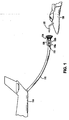
FIG.1 shows an elongate hose and attached drogue extending from a tanker aircraft according to one embodiment of the present invention and a second aircraft carrying a refueling probe approaching the tanker aircraft; -
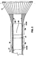
FIG. 2 shows a partial cross-section of a fuse device according to one embodiment of the present invention wherein the fuse device is disposed between an elongate hose and a drogue as part of a probe and drogue in-flight refueling system; -
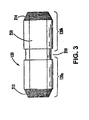
FIG. 3 shows a fuse device according to one embodiment of the present invention wherein the cross section of the fuse device is minimized at a channel defined in an outer surface of the fuse device; -
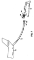
FIG. 4 shows an in-flight refueling system according to one embodiment of the present invention wherein the fuse device has been separated in response to a separating force so that the elongate hose is separated from the drogue. - The present inventions now will be described more fully hereinafter with reference to the accompanying drawings, in which some, but not all embodiments of the invention are shown. Indeed, these inventions may be embodied in many different forms and should not be construed as limited to the embodiments set forth herein; rather, these embodiments are provided so that this disclosure will satisfy applicable legal requirements. Like numbers refer to like elements throughout.
- While the in-flight refueling system and method embodiments of the present invention are described below in the context of a
fuse device 120 disposed between anelongate hose 112 and adrogue 114, it should be understood that the embodiments of the present invention may also be utilized to achieve the controlled and predictable separation of a variety of in-flight refueling system components that may be subjected to a separation force during the course of an in-flight refueling operation, including, but not limited to, connections between atanker aircraft 110 and an end of theelongate hose 112, connections between adjacent and separable portions ofelongate hose 112, connections between a fuel reservoir and a probe and drogue in-flight refueling system carried by atanker aircraft 110 and other fluid connections between in-flight refueling system components that may require safely controlled and predictable separation when subjected to a separating force. It should also be understood that the embodiments of the present invention may also be utilized in in-flight refueling systems other than probe and drogue refueling systems, such as, for instance boom in-flight refueling systems and/or wing-mounted pod-based probe and drogue in-flight refueling systems. -
FIG. 1 shows a schematic view of a probe and drogue in-flight refueling operation wherein atanker aircraft 110 is shown carrying and extending anelongate hose 112 having a first end (not shown) carried by (and in fluid communication with a fuel reservoir onboard) thetanker aircraft 110 and adrogue 114 operably engaged with and in fluid communication with an opposingsecond end 113 of theelongate hose 112. The first end of theelongate hose 112 may be operably engaged with a hose take-up assembly (such as a roller drum) carried by thetanker aircraft 110, and thesecond end 113 of theelongate hose 112 and thedrogue 114 operably engaged therewith way be configured to be taken up into a tunnel or/other aperture defined in a fuselage of thetanker aircraft 110 as the hose take-up assembly retracts theelongate hose 112. Also shown inFIG. 1 is asecond aircraft 130 carrying a refuelingprobe 132 configured to enter and become operably engaged with thedrogue 114 so as to enable fuel to pass from thetanker aircraft 110 through theelongate hose 112 to thesecond aircraft 130 as part of an in-flight refueling operation. An operator of the second aircraft (either, for instance, an on-board operator or a remote operator in the case of an unmanned aircraft (UAV)) is responsible for positioning thesecond aircraft 130 with respect to thedrogue 114 such that the refuelingprobe 132 may enter and engage thedrogue 114. Also shown is afuse device 120, disposed between thesecond end 113 of theelongate hose 112 and thedrogue 114 so as to allow fluid communication between theelongate hose 112 and thedrogue 114. Thefuse device 120, in some embodiments, may be disposed between thesecond end 113 of theelongate hose 112 and thedrogue 114 in a low-profile arrangement (as shown generally inFIG. 2 ) such that thefuse device 120 may be taken up into the tunnel or other aperture defined in a fuselage of thetanker aircraft 110 as the hose take-up assembly retracts theelongate hose 112. Furthermore, thefuse device 120 is configured to disengage the drogue from the elongate hose in response to a separating force experienced thereby, such that the elongate hose is separable from the drogue in response to the separating force. More particularly, in some embodiments, thefuse device 120 may be separable into afirst segment 120a operably engaged with thesecond end 113 of theelongate hose 112 and asecond segment 120b operably engaged with thedrogue 114 in response to a separating force experienced by thefuse device 120. Thus, according to the embodiments of the present invention, thedrogue 114 may be separable from thesecond end 113 of theelongate hose 112 in response to the separating force (as shown in FIG. 5). Although thefuse device 120 is shown to be between thesecond end 113 of theelongate hose 112 and thedrogue 114, thefuse device 120 may be positioned elsewhere along the hose such that thefuse device 120 is disposed between two portions of theelongate hose 112, thereby allowing the two portions of theelongate hose 112 to be separable in a similar manner when subjected to the separating force. -
FIG. 2 shows a more detailed view of thefuse device 120 and its disposition between theelongate hose 112 and thedrogue 114. Thefuse device 120 may define, for instance, afuel conduit 220 therein such that fuel may pass from thesecond end 113 of theelongate hose 112 through the first andsecond segments drogue 114 to a refueling probe 132 (seeFIG. 1 ) carried by asecond aircraft 130. An interior of thedrogue 114 may further comprise, for instance, acatch mechanism 250 configured to be capable of securing therefueling probe 132 carried by thesecond aircraft 130 after the operator of thesecond aircraft 130 has positioned thesecond aircraft 130 such that therefueling probe 132 enters thedrogue 114. Furthermore, one skilled in the art will appreciate that the operator of thesecond aircraft 130 may also be responsible for disengaging therefueling probe 132 from thedrogue 114 at the conclusion of the in-flight refueling operation by, for instance, decelerating with respect to thetanker aircraft 110 so as to exert a tension force on thedrogue 114 and thecatch mechanism 250 that holds therefueling probe 132 within thedrogue 114. In some cases, however, thecatch mechanism 250 may malfunction such that the operator of thesecond aircraft 130 may be unable to disengage therefueling probe 132 from thedrogue 114 without exerting an excessive tension force on thedrogue 114 and attachedelongate hose 112 carried by thetanker aircraft 110. Such tension forces may, in some cases, be transferred along theelongate hose 112 and into a fuselage of thetanker aircraft 110 to, for instance, a rotating drum hose take-up assembly. Such tension forces may also, if allowed to continue, tear or break theelongate hose 112 at an unpredictable point along the length of theelongate hose 112. - Thus, according to embodiments of the present invention, as shown in
FIG. 2 , thefuse device 120 may comprise aseparable portion 210 disposed between the first andsecond segments fuse device 120 may separate into afirst segment 120a that may remain attached to thesecond end 113 of theelongate hose 112 and asecond segment 120b that may remain attached to thedrogue 114 in response to a separating force (such as, for example, a predetermined tension force) experienced by thefuse device 120. According to some embodiments, the separating force may be predetermined such that the separating force may be less than a breakage force required to damage theelongate hose 112. - The
fuse device 120 may be connected to theelongate hose 112 and, in the illustrated embodiment, to thedrogue 114 in any manner known to those skilled in the art. As shown inFIG. 2 , however, some embodiments of the in-flight refueling system of the present invention may comprise afuse device 120 including a first threadedportion 212 configured to be capable of operably engaging a first threaded surface 230 disposed on thesecond end 113 of theelongate hose 112 and a second threadedportion 214 configured to be capable of operably engaging a second threaded surface 240 disposed on thedrogue 114. According to other embodiments, the fuse device may be configured so as to be capable of operably engaging thesecond end 113 of theelongate hose 112 and thedrogue 114 by a variety of other connection mechanisms and techniques that may include, but are not limited to, bolts, rivets, adhesives, clamps, frictional press-fit components, and/or other mechanisms that may be suitable for connecting thefuse device 120 with thesecond end 113 of theelongate hose 112 as well as with thedrogue 114 so as to be disposed between theelongate hose 112 and thedrogue 114 and to allow fluid communication therebetween. In other instances, thefuse device 120 may be operably engaged with thesecond end 113 of theelongate hose 112 and thedrogue 114 by a first connection mechanism as described above and also operably engaged therewith via a redundant safety mechanism (such as a safety wire connection) such that thefuse device 120 is connected to theelongate hose 112 and, in the illustrated embodiment, to thedrogue 114 in a manner that is sufficiently secure such that the separating force required to cause theseparable portion 210 to fail is less than that required to cause the connections of thefuse device 120 to theelongate hose 112 anddrogue 114 to fail. In addition, regardless of the type of connection, thefuse device 120 is advantageously connected to theelongate hose 112 and, in the illustrated embodiment, to thedrogue 114 in a manner that is sufficiently secure such that the separating force required to cause theseparable portion 210 to fail is less than that required to cause the connections of thefuse device 120 to theelongate hose 112 anddrogue 114 to fail, thereby ensuring that theseparable portion 210 may fail while the opposed first andsecond segments fuse device 120 remain coupled to theelongate hose 112 and thedrogue 114. - Thus, in advantageous embodiments of the present invention, should the
fuse device 120 be separated into thefirst segment 120a and thesecond segment 120b by, for instance, a separating force exerted during an in-flight refueling operation, both thetanker aircraft 110 and thesecond aircraft 130 may land safely with theelongate hose 112 anddrogue 114 still attached respectively thereto (see FIG. 5, depicting thefuse device 120 after separation into first andsecond segments tanker aircraft 110 and thesecond aircraft 130 have safely landed, a technician may examine the first andsecond segments elongate hose 112 and thedrogue 114, respectively. Thus, the technician may then simply insert anew fuse device 120 into a disposition between thesecond end 113 of theelongate hose 112 and thedrogue 114 so that the probe and drogue in-flight refueling system may be returned to operational status in a relatively quick procedure when compared to repairs and/or inspections that must be completed in conventional probe and drogue in-flight refueling systems wherein theelongate hose 112 has been torn, sheared, and/or broken by a separating force. The technician may also, in some cases, examine thedrogue 114 and its associatedcatch mechanism 250 in order to attempt to determine the cause for the catch mechanism's 250 failure to release therefueling probe 132 upon the exertion of a tension force exceeding the separation force that caused, for instance, the separation of thefuse device 120 into first andsecond segments catch mechanism 250, the technician may also repair and/or replace thedrogue 114 and its associatedcatch mechanism 250 when replacing thefuse device 120. - As shown in
FIGS. 1 and2 , and as described generally above, thefuse device 120 may comprise aseparable portion 210 configured to be capable of failing in response to a separating force such that thefuse device 120 may separate into afirst segment 120a that may remain attached to thesecond end 113 of theelongate hose 112 and asecond segment 120b that may remain attached to thedrogue 114 in response to the separating force experienced by thefuse device 120. The first and second segments may be composed of for instance, a metal, metallic alloy, polymer, composite material, or other material suitable for maintaining structural integrity as the adjacentseparable portion 210 is allowed to controllably fail as described in more detail below. As shown inFIG. 3 theseparable portion 210 may comprise a channel defined in thefuse device 120, wherein the channel is formed so as to purposely weaken thefuse device 120 such that thefuse device 120 will fail at a predictable point (the channel (or separable portion 210), for instance) in response to the applied separating force. According to some embodiments, the channel may be defined in an outer surface of the fuse device 250 (as shown inFIG. 3 ). In other embodiments, the channel may be defined in an inner surface of thefuse device 120. One skilled in the art will appreciate that theseparable portion 210 of thefuse device 120 may comprise a pair of complementary channels defined in the inner and outer surfaces of thefuse device 120 so long as a fuel conduit may be maintained between the adjacent portions of the in-flight refueling system that may be connected by thefuse device 120. In addition, according to other embodiments, theseparable portion 210 of thefuse device 120 may further comprise a material configured to fail elastically or after deforming in a substantially plastic mode prior to the failure of thefirst segment 120a, thesecond segment 120b, theelongate hose 112, or other components of the in-flight refueling system. The material used to produce theseparable portion 210 may comprise, for instance, a metal, metallic alloy, polymer, composite material, or other material suitable for failing in a controlled and predictable manner in response to the separating force. -
FIG. 4 shows an in-flight refueling system according to one embodiment of the present invention wherein the fuse device 120 (which is disposed between asecond end 113 of theelongate hose 112 and thedrogue 114 carried by thetanker aircraft 110 as part of a probe and drogue in-flight refueling system) has been separated into afirst segment 120a operably engaged with thesecond end 113 of theelongate hose 112 and asecond segment 120b operably engaged with adrogue 114. As shown inFIG. 4 the drogue 114 (and thesecond segment 120b of thefuse device 120 operably engaged therewith) has been separated from the in-flight refueling system due to, for instance, an emergency wherein a force at least as great as the separating force has been applied to thefuse device 120. Thus, thedrogue 114 may be carried by, for instance, therefueling probe 132 of thesecond aircraft 130. While this arrangement is not optimal (as thedrogue 114 may block the view of an operator of thesecond aircraft 130 as well as introduce aerodynamic disturbances to the flight characteristics of the second aircraft 130), the second aircraft may still, however, land safely with thedrogue 114 carried thereby without the danger of a portion of theelongate hose 112 being attached to thedrogue 114 and possibly striking thesecond aircraft 130 or being drawn into a jet intake of thesecond aircraft 130. In addition, thefirst segment 120a of thefuse device 120 is shown operably engaged with thesecond end 113 of theelongate hose 112. Upon the separation of thefuse device 120, an operator of the in-flight refueling system carried by thetanker aircraft 110 prevents a flow of fuel through the elongate hose, by, for instance, actuating a fuel shut-off valve (not shown) that is disposed within a fuselage of thetanker aircraft 110 so as to prevent the passage of fuel through theelongate hose 112 and out into the open air via the separatedfirst segment 120a of thefuse device 120. In addition, the in-flight refueling system carried by thetanker aircraft 110 may further comprise a guillotine device configured to jettison the elongate hose 112 (and thefirst segment 120a of thefuse device 120 attached thereto) if, for instance, the in-flight refueling system is incapable of safely retracting theelongate hose 112 into a fuselage of thetanker aircraft 110. - Referring again to
FIG. 1 , the embodiments of the present invention also provide a method for facilitating the emergency separation of adrogue 114 from anelongate hose 112 wherein thedrogue 114 andelongate hose 112 are operably engaged and in fluid communication via afuse device 120 disposed therebetween as part of an in-flight refueling system. The method may comprise the steps of exerting a separating force on the drogue 114 (such as by inserting arefueling probe 132 carried by asecond aircraft 130 into thedrogue 114 and subsequently decelerating thesecond aircraft 130 with respect to the movingdrogue 114; and disengaging thedrogue 114 fromelongate hose 112 at thefuse device 120 in response to a separating force exerted on theelongate hose 112 and thedrogue 114, such that the first portion of the elongate hose may be separable from thedrogue 114 in response to the separating force. In other embodiments of the method of the present invention, the disengaging step may further comprise the step of separating thefuse device 120 into afirst segment 120a operably engaged with theelongate hose 112 and asecond segment 120b operably engaged with thedrogue 114 in response to the separating force exerted on thedrogue 114. The method of the present invention further comprises blocking a flow of fuel through theelongate hose 112 so as to prevent the flow of fuel from exiting theelongate hose 112 via thefirst segment 120a. This blocking step may be accomplished by, for instance, actuating a fuel control valve carried by thetanker aircraft 110 so as to shut off the flow of fuel through the in-flight refueling system. Furthermore, according to other embodiments, the separating step (described in more detail above) may further comprise separating thefuse device 120 using a separating force that is less than a breakage force required to damage theelongate hose 112. Thus, thefuse device 120 may fail prior to the breakage of theelongate hose 112 so as to prevent the unpredictable and possibly violent breakage of theelongate hose 112 and/or other components of the in-flight refueling system carried by thetanker aircraft 110.
Claims (2)
- A method for facilitating the emergency separation of a drogue from an elongate hose wherein the drogue and elongate hose are operably engaged and in fluid communication via a fuse device disposed therebetween as part of an in-flight refuelling system, wherein the fuse device is a cylindrical conduit having a separable portion which comprises a channel to weaken the fuse device and allowing its separation into a first segment operably engaged with the second end of the elongate hose and a second segment operably engaged with the drogue in response to a separating force experienced thereby, such that the drogue is separable from the second end of the elongate hose in response to the separating force, the method comprising:exerting a separating force on the drogue;disengaging the drogue from the elongate hose at the fuse device in response to a separating force exerted on the elongate hose and the drogue, such that the first segment is separated from the second segment in response to the separating force, andblocking a flow of fuel through the elongate hose so as to prevent the flow of fuel from exiting the elongate hose via the first segment,wherein the channel is defined in an inner surface and/or an outer surface of the fuse device.
- A method according to claim 1, wherein the disengaging step further comprises disengaging the drogue from the elongate hose at the fuse device using a separating force that is less than a breakage force required to damage the elongate hose.
Applications Claiming Priority (2)
| Application Number | Priority Date | Filing Date | Title |
|---|---|---|---|
| US10/890,664 US7281687B2 (en) | 2004-07-14 | 2004-07-14 | In-flight refueling system and method for facilitating emergency separation of in-flight refueling system components |
| PCT/US2005/024603 WO2006085985A1 (en) | 2004-07-14 | 2005-07-11 | In-flight refueling system and method for facilitating emergency separation of in-flight refueling system components |
Publications (3)
| Publication Number | Publication Date |
|---|---|
| EP1765670A1 EP1765670A1 (en) | 2007-03-28 |
| EP1765670B1 EP1765670B1 (en) | 2010-02-10 |
| EP1765670B2 true EP1765670B2 (en) | 2015-12-23 |
Family
ID=35598467
Family Applications (1)
| Application Number | Title | Priority Date | Filing Date |
|---|---|---|---|
| EP05856875.9A Active EP1765670B2 (en) | 2004-07-14 | 2005-07-11 | In-flight refueling system and method for facilitating emergency separation of in-flight refueling system components |
Country Status (5)
| Country | Link |
|---|---|
| US (2) | US7281687B2 (en) |
| EP (1) | EP1765670B2 (en) |
| AT (1) | ATE457268T1 (en) |
| DE (1) | DE602005019298D1 (en) |
| WO (1) | WO2006085985A1 (en) |
Families Citing this family (25)
| Publication number | Priority date | Publication date | Assignee | Title |
|---|---|---|---|---|
| US7309047B2 (en) * | 2005-02-25 | 2007-12-18 | The Boeing Company | Systems and methods for controlling flexible communication links used for aircraft refueling |
| US7469863B1 (en) * | 2005-03-24 | 2008-12-30 | The Boeing Company | Systems and methods for automatically and semiautomatically controlling aircraft refueling |
| US7213787B2 (en) * | 2005-06-07 | 2007-05-08 | The Boeing Company | Valves for annular conduits including aircraft fuel conduits and associated systems and methods |
| US7637458B2 (en) * | 2005-06-08 | 2009-12-29 | The Boeing Company | Systems and methods for providing back-up hydraulic power for aircraft, including tanker aircraft |
| US7293741B2 (en) * | 2005-06-09 | 2007-11-13 | The Boeing Company | System and methods for distributing loads from fluid conduits, including aircraft fuel conduits |
| US7533850B2 (en) * | 2005-06-09 | 2009-05-19 | The Boeing Company | Fittings with redundant seals for aircraft fuel lines, fuel tanks, and other systems |
| US7581700B2 (en) * | 2005-06-09 | 2009-09-01 | The Boeing Company | Adjustable fittings for attaching support members to fluid conduits, including aircraft fuel conduits, and associated systems and methods |
| US7458543B2 (en) * | 2005-06-10 | 2008-12-02 | The Boeing Company | Aerial refueling system |
| US7219857B2 (en) * | 2005-06-20 | 2007-05-22 | The Boeing Company | Controllable refueling drogues and associated systems and methods |
| US20070040065A1 (en) * | 2005-08-19 | 2007-02-22 | Von Thal German | Flexible refueling boom extendable tube |
| ATE419178T1 (en) * | 2006-08-29 | 2009-01-15 | Eads Constr Aeronauticas Sa | INTELLIGENT REFUELING BOOM POINT DEVICE |
| US8074931B2 (en) * | 2007-11-12 | 2011-12-13 | The Boeing Company | Drogue deploying/retrieval device, system, and method |
| GB201012737D0 (en) * | 2010-07-29 | 2010-09-15 | Airbus Operations Ltd | Improvements to aircraft refuel system piping |
| GB201102184D0 (en) * | 2011-02-08 | 2011-03-23 | Flight Refueling Ltd | Air-to-air refuelling drogue assemblies |
| US9150311B2 (en) | 2012-01-04 | 2015-10-06 | Israel Aerospace Industries Ltd. | Systems and methods for air vehicles |
| GB2500669B (en) * | 2012-03-29 | 2016-03-30 | Icon Polymer Group | Hose for conveying fluid |
| CA2884639A1 (en) | 2012-09-14 | 2014-03-20 | The Government of the United State of America as represented by the Secretary of the Navy | Magnetically attracted connector system and method |
| US10597166B2 (en) | 2012-12-12 | 2020-03-24 | Northrop Grumman Systems Corporation | In-flight refueling probe for an aircraft |
| US9631744B2 (en) | 2013-10-09 | 2017-04-25 | Mide Technology Corporation | Aerial refueling hose |
| US9540115B2 (en) | 2015-04-28 | 2017-01-10 | Northrop Grumman Systems Corporation | Dual mode frangible refueling nozzle |
| EP3342716A1 (en) * | 2016-12-28 | 2018-07-04 | Airbus Defence and Space SA | Aircraft refueling boom system with nozzle security means |
| IL253015B2 (en) | 2017-06-18 | 2023-07-01 | Israel Aerospace Ind Ltd | System and method for refueling air vehicles |
| IL253407B (en) | 2017-07-10 | 2020-08-31 | Israel Aerospace Ind Ltd | Refueling |
| WO2023112023A1 (en) * | 2021-12-16 | 2023-06-22 | Israel Aerospace Industries Ltd. | Boom member for refueling air vehicles |
| CN116663457B (en) * | 2023-07-25 | 2023-11-17 | 山东大学 | Conical drag parachute drag resistance prediction method and system based on half-analytic equation |
Family Cites Families (47)
| Publication number | Priority date | Publication date | Assignee | Title |
|---|---|---|---|---|
| US2642297A (en) * | 1948-09-10 | 1953-06-16 | Breco Mfg Company | Coupling |
| US2634927A (en) * | 1949-01-18 | 1953-04-14 | Flight Refueling Ltd | Apparatus for transferring fuel and other liquids from one aircraft to another in flight |
| US2793828A (en) * | 1953-05-18 | 1957-05-28 | Boeing Co | Airplane inflight refueling apparatus |
| US2973171A (en) * | 1957-01-15 | 1961-02-28 | Flight Refueling Inc | In-flight connection for aircraft |
| US3062247A (en) * | 1959-12-23 | 1962-11-06 | Buckeye Iron And Brass Works | Automatic dispensing nozzle |
| US3687491A (en) * | 1970-01-06 | 1972-08-29 | Goodall Semi Metallic Hose & M | Hose coupling |
| US3915206A (en) * | 1973-10-12 | 1975-10-28 | Weil Mclain Company Inc | Gasoline dispensing and vapor recovery system |
| US4090539A (en) * | 1976-11-10 | 1978-05-23 | The B. F. Goodrich Company | Anti-pollution service station assembly |
| US4167958A (en) * | 1978-03-20 | 1979-09-18 | Atlantic Richfield Company | Hydrocarbon fuel dispensing, vapor controlling system |
| US4288845A (en) * | 1979-08-08 | 1981-09-08 | The United States Of America As Represented By The Secretary Of The Air Force | Aerial refueling receptacle floodlights-spoiler and fuselage, nose mounted |
| US4361165A (en) * | 1980-08-07 | 1982-11-30 | Exxon Research And Engineering Co. | Breakaway pipe coupling with automatically closed valves |
| US4438793A (en) * | 1981-05-04 | 1984-03-27 | International Telephone & Telegraph Corp. | Aerial refueling boom nozzle |
| US4625746A (en) * | 1982-04-06 | 1986-12-02 | Calvin John H | Automatic fluid sealing mechanism for a conduit with a frangible connector |
| US4617975A (en) * | 1982-07-23 | 1986-10-21 | Charles Rabushka | Tension actuated uncoupler |
| US4615547A (en) * | 1982-11-24 | 1986-10-07 | Husky Corporation | Multi-plane swivel connector |
| US4687033A (en) * | 1984-03-15 | 1987-08-18 | Gilbarco, Inc. | Venturi liquid evacuator system for maintaining clear vapor path in vapor recovery hose |
| US4691941A (en) * | 1984-06-11 | 1987-09-08 | Charles Rabushka | Tension actuated uncoupler |
| US4667883A (en) * | 1984-12-17 | 1987-05-26 | Husky Corporation | Butterfly valve for fluid flow line |
| US4828183A (en) * | 1984-12-17 | 1989-05-09 | Husky Corporation | Butterfly valve for fluid flow line |
| US4682795A (en) * | 1985-08-02 | 1987-07-28 | Charles Rabushka | Tension actuated uncoupler |
| US4899792A (en) * | 1988-02-29 | 1990-02-13 | Emco Wheaton, Inc. | Fueling nozzle providing combination breakaway and swivel coupling |
| US4827977A (en) * | 1988-10-11 | 1989-05-09 | Husky Corporation | Breakaway hose coupling |
| FR2638731B1 (en) * | 1988-11-09 | 1991-02-08 | Fmc Europe | METHOD FOR PROVIDING A DISCONNECTION BETWEEN A FLUID LOADING ARM AND A TANK, ONE OF WHICH IS CARRIED BY A VEHICLE IN THE EVENT OF AN UNEXPECTED DEPARTURE OF THE VEHICLE; FLUID LOADING ARM IMPLEMENTING THIS PROCESS; SAFETY DISCONNECTOR FOR ITS IMPLEMENTATION |
| US5131438A (en) * | 1990-08-20 | 1992-07-21 | E-Systems, Inc. | Method and apparatus for unmanned aircraft in flight refueling |
| US5326052A (en) * | 1991-10-02 | 1994-07-05 | Enig Associates, Inc. | Controllable hose-and-drogue in-flight refueling system |
| US5506570A (en) * | 1994-03-28 | 1996-04-09 | Scott; Paul B. | Gasoline dispenser warning announces |
| US5564471A (en) * | 1995-01-23 | 1996-10-15 | Dover Corporation | Fuel hose breakaway unit |
| US5660206A (en) * | 1995-04-25 | 1997-08-26 | Walbro Corporation | Fuel tank filler neck check valve |
| US5826610A (en) * | 1996-05-06 | 1998-10-27 | Vita International, Inc. | Breakaway coupling device |
| US5720327A (en) * | 1996-05-24 | 1998-02-24 | Foster, Jr.; James C. | Vehicle safety fueling system |
| US5758682A (en) * | 1996-06-05 | 1998-06-02 | Metal Goods Manufacturing Company | Safety shut off valve |
| US5921266A (en) * | 1997-06-03 | 1999-07-13 | Mapco, Inc. | Safety system for transfer of pressurized fluid |
| US6021823A (en) * | 1997-08-18 | 2000-02-08 | Hale; David L. | Method and apparatus for pull away prevention |
| US5906336A (en) * | 1997-11-14 | 1999-05-25 | Eckstein; Donald | Method and apparatus for temporarily interconnecting an unmanned aerial vehicle |
| US6050297A (en) * | 1998-11-17 | 2000-04-18 | Dresser Industries, Inc. | Breakaway hose coupling for fuel dispensers |
| US6464173B1 (en) * | 1999-09-30 | 2002-10-15 | Sargent Fletcher, Inc. | Paradrogue assembly |
| US6182695B1 (en) * | 2000-04-28 | 2001-02-06 | Husky Corporation | Breakaway coupling and coupler therefor |
| US6601800B2 (en) * | 2000-09-19 | 2003-08-05 | Charles Howard Ollar | Aerial refueling pod and constant tension line apparatus |
| US6604711B1 (en) * | 2000-11-20 | 2003-08-12 | Sargent Fletcher, Inc. | Autonomous system for the aerial refueling or decontamination of unmanned airborne vehicles |
| US6334474B1 (en) * | 2001-04-26 | 2002-01-01 | Brent D. Rababy | Breakaway separation detection and alert system |
| US6692034B2 (en) * | 2001-10-29 | 2004-02-17 | Chart Inc. | Breakaway device for fueling stations |
| US20030136874A1 (en) * | 2001-12-10 | 2003-07-24 | Gjerdrum David Michael | Method for safer mid-air refueling |
| US6588465B1 (en) * | 2002-01-15 | 2003-07-08 | West Coast Netting, Inc. | Passive variable speed drogue |
| US6651933B1 (en) * | 2002-05-01 | 2003-11-25 | The Boeing Company | Boom load alleviation using visual means |
| US6786455B1 (en) * | 2002-09-05 | 2004-09-07 | Asher Bartov | Method for engaging a probe and drogue for aerial refueling |
| US6669145B1 (en) * | 2002-12-30 | 2003-12-30 | The Boeing Company | Apparatus, method and system for fluid-motion-powered modulation of a retroreflector for remote position sensing |
| US7036770B2 (en) * | 2003-07-25 | 2006-05-02 | The Boeing Company | Methods and apparatus for illumination of refueling hoses |
-
2004
- 2004-07-14 US US10/890,664 patent/US7281687B2/en not_active Expired - Fee Related
-
2005
- 2005-07-11 AT AT05856875T patent/ATE457268T1/en not_active IP Right Cessation
- 2005-07-11 WO PCT/US2005/024603 patent/WO2006085985A1/en not_active Application Discontinuation
- 2005-07-11 EP EP05856875.9A patent/EP1765670B2/en active Active
- 2005-07-11 DE DE602005019298T patent/DE602005019298D1/en active Active
-
2007
- 2007-07-27 US US11/829,369 patent/US7516920B2/en not_active Expired - Fee Related
Also Published As
| Publication number | Publication date |
|---|---|
| DE602005019298D1 (en) | 2010-03-25 |
| US20060011782A1 (en) | 2006-01-19 |
| EP1765670A1 (en) | 2007-03-28 |
| US7516920B2 (en) | 2009-04-14 |
| US20080017757A1 (en) | 2008-01-24 |
| EP1765670B1 (en) | 2010-02-10 |
| WO2006085985A1 (en) | 2006-08-17 |
| ATE457268T1 (en) | 2010-02-15 |
| US7281687B2 (en) | 2007-10-16 |
Similar Documents
| Publication | Publication Date | Title |
|---|---|---|
| EP1765670B2 (en) | In-flight refueling system and method for facilitating emergency separation of in-flight refueling system components | |
| EP1827979B1 (en) | Aerial refuelling vehicle | |
| US20190375505A1 (en) | Detachable Pilotable Capsules and Aircrafts Including Detachable Pilotable Capsules | |
| CN109204774B (en) | Frangible fastener and method for manufacturing unmanned aerial vehicle | |
| EP3268280B1 (en) | Intelligent parachute rescue system for manned and unmanned aerial vehicles | |
| US20090014587A1 (en) | Aircraft safety system | |
| US20080173763A1 (en) | Fuel jettison system | |
| EP1824734B1 (en) | In-flight refueling system and method for preventing oscillations in system components | |
| US8256716B2 (en) | Aircraft flight termination system and method | |
| EP3115562B1 (en) | Pressure relief door assembly | |
| US11161594B2 (en) | Flap support breakaway and fail safety configuration | |
| US5108049A (en) | Device for overcoming the problem of crew safety during a spacecraft launch and improve the joints connecting the segments of the solid rocket booster | |
| US9540115B2 (en) | Dual mode frangible refueling nozzle | |
| EP3546371B1 (en) | Installation tool and method | |
| EP2293982B1 (en) | Fuel jettison system | |
| EP3342716A1 (en) | Aircraft refueling boom system with nozzle security means | |
| RU2473003C1 (en) | Board detachable joint | |
| US10538330B2 (en) | Store ejection system and method of discharging a store from a vehicle | |
| EP3140576B1 (en) | Fuel system breakaway valve reaction bridge and reaction collar | |
| RU2123458C1 (en) | Flying vehicle spin-recovery system | |
| DE102009007731A1 (en) | Flight crash device for a missile | |
| US10072769B2 (en) | Charged cylinder valve retention arrangement | |
| WO2023112023A1 (en) | Boom member for refueling air vehicles | |
| CN116294831A (en) | Solid carrier rocket one-stage recovery system and method | |
| CLARKE et al. | V/STOL aircraft testing for the sea control ship environment |
Legal Events
| Date | Code | Title | Description |
|---|---|---|---|
| PUAI | Public reference made under article 153(3) epc to a published international application that has entered the european phase |
Free format text: ORIGINAL CODE: 0009012 |
|
| 17P | Request for examination filed |
Effective date: 20061208 |
|
| AK | Designated contracting states |
Kind code of ref document: A1 Designated state(s): AT BE BG CH CY CZ DE DK EE ES FI FR GB GR HU IE IS IT LI LT LU LV MC NL PL PT RO SE SI SK TR |
|
| DAX | Request for extension of the european patent (deleted) | ||
| 17Q | First examination report despatched |
Effective date: 20080311 |
|
| GRAP | Despatch of communication of intention to grant a patent |
Free format text: ORIGINAL CODE: EPIDOSNIGR1 |
|
| GRAS | Grant fee paid |
Free format text: ORIGINAL CODE: EPIDOSNIGR3 |
|
| GRAA | (expected) grant |
Free format text: ORIGINAL CODE: 0009210 |
|
| AK | Designated contracting states |
Kind code of ref document: B1 Designated state(s): AT BE BG CH CY CZ DE DK EE ES FI FR GB GR HU IE IS IT LI LT LU LV MC NL PL PT RO SE SI SK TR |
|
| REG | Reference to a national code |
Ref country code: GB Ref legal event code: FG4D |
|
| REG | Reference to a national code |
Ref country code: CH Ref legal event code: EP |
|
| REG | Reference to a national code |
Ref country code: IE Ref legal event code: FG4D |
|
| REF | Corresponds to: |
Ref document number: 602005019298 Country of ref document: DE Date of ref document: 20100325 Kind code of ref document: P |
|
| REG | Reference to a national code |
Ref country code: NL Ref legal event code: VDEP Effective date: 20100210 |
|
| LTIE | Lt: invalidation of european patent or patent extension |
Effective date: 20100210 |
|
| PG25 | Lapsed in a contracting state [announced via postgrant information from national office to epo] |
Ref country code: LT Free format text: LAPSE BECAUSE OF FAILURE TO SUBMIT A TRANSLATION OF THE DESCRIPTION OR TO PAY THE FEE WITHIN THE PRESCRIBED TIME-LIMIT Effective date: 20100210 Ref country code: ES Free format text: LAPSE BECAUSE OF FAILURE TO SUBMIT A TRANSLATION OF THE DESCRIPTION OR TO PAY THE FEE WITHIN THE PRESCRIBED TIME-LIMIT Effective date: 20100521 Ref country code: IS Free format text: LAPSE BECAUSE OF FAILURE TO SUBMIT A TRANSLATION OF THE DESCRIPTION OR TO PAY THE FEE WITHIN THE PRESCRIBED TIME-LIMIT Effective date: 20100610 Ref country code: PT Free format text: LAPSE BECAUSE OF FAILURE TO SUBMIT A TRANSLATION OF THE DESCRIPTION OR TO PAY THE FEE WITHIN THE PRESCRIBED TIME-LIMIT Effective date: 20100611 |
|
| PG25 | Lapsed in a contracting state [announced via postgrant information from national office to epo] |
Ref country code: SI Free format text: LAPSE BECAUSE OF FAILURE TO SUBMIT A TRANSLATION OF THE DESCRIPTION OR TO PAY THE FEE WITHIN THE PRESCRIBED TIME-LIMIT Effective date: 20100210 Ref country code: PL Free format text: LAPSE BECAUSE OF FAILURE TO SUBMIT A TRANSLATION OF THE DESCRIPTION OR TO PAY THE FEE WITHIN THE PRESCRIBED TIME-LIMIT Effective date: 20100210 Ref country code: LV Free format text: LAPSE BECAUSE OF FAILURE TO SUBMIT A TRANSLATION OF THE DESCRIPTION OR TO PAY THE FEE WITHIN THE PRESCRIBED TIME-LIMIT Effective date: 20100210 Ref country code: FI Free format text: LAPSE BECAUSE OF FAILURE TO SUBMIT A TRANSLATION OF THE DESCRIPTION OR TO PAY THE FEE WITHIN THE PRESCRIBED TIME-LIMIT Effective date: 20100210 Ref country code: AT Free format text: LAPSE BECAUSE OF FAILURE TO SUBMIT A TRANSLATION OF THE DESCRIPTION OR TO PAY THE FEE WITHIN THE PRESCRIBED TIME-LIMIT Effective date: 20100210 |
|
| PG25 | Lapsed in a contracting state [announced via postgrant information from national office to epo] |
Ref country code: RO Free format text: LAPSE BECAUSE OF FAILURE TO SUBMIT A TRANSLATION OF THE DESCRIPTION OR TO PAY THE FEE WITHIN THE PRESCRIBED TIME-LIMIT Effective date: 20100210 Ref country code: BE Free format text: LAPSE BECAUSE OF FAILURE TO SUBMIT A TRANSLATION OF THE DESCRIPTION OR TO PAY THE FEE WITHIN THE PRESCRIBED TIME-LIMIT Effective date: 20100210 Ref country code: CY Free format text: LAPSE BECAUSE OF FAILURE TO SUBMIT A TRANSLATION OF THE DESCRIPTION OR TO PAY THE FEE WITHIN THE PRESCRIBED TIME-LIMIT Effective date: 20100210 Ref country code: EE Free format text: LAPSE BECAUSE OF FAILURE TO SUBMIT A TRANSLATION OF THE DESCRIPTION OR TO PAY THE FEE WITHIN THE PRESCRIBED TIME-LIMIT Effective date: 20100210 Ref country code: GR Free format text: LAPSE BECAUSE OF FAILURE TO SUBMIT A TRANSLATION OF THE DESCRIPTION OR TO PAY THE FEE WITHIN THE PRESCRIBED TIME-LIMIT Effective date: 20100511 Ref country code: NL Free format text: LAPSE BECAUSE OF FAILURE TO SUBMIT A TRANSLATION OF THE DESCRIPTION OR TO PAY THE FEE WITHIN THE PRESCRIBED TIME-LIMIT Effective date: 20100210 Ref country code: SE Free format text: LAPSE BECAUSE OF FAILURE TO SUBMIT A TRANSLATION OF THE DESCRIPTION OR TO PAY THE FEE WITHIN THE PRESCRIBED TIME-LIMIT Effective date: 20100210 |
|
| PLBI | Opposition filed |
Free format text: ORIGINAL CODE: 0009260 |
|
| PG25 | Lapsed in a contracting state [announced via postgrant information from national office to epo] |
Ref country code: SK Free format text: LAPSE BECAUSE OF FAILURE TO SUBMIT A TRANSLATION OF THE DESCRIPTION OR TO PAY THE FEE WITHIN THE PRESCRIBED TIME-LIMIT Effective date: 20100210 Ref country code: BG Free format text: LAPSE BECAUSE OF FAILURE TO SUBMIT A TRANSLATION OF THE DESCRIPTION OR TO PAY THE FEE WITHIN THE PRESCRIBED TIME-LIMIT Effective date: 20100510 Ref country code: CZ Free format text: LAPSE BECAUSE OF FAILURE TO SUBMIT A TRANSLATION OF THE DESCRIPTION OR TO PAY THE FEE WITHIN THE PRESCRIBED TIME-LIMIT Effective date: 20100210 |
|
| 26 | Opposition filed |
Opponent name: EADS CONSTRUCCIONES AERONAUTICAS S.A. Effective date: 20101102 |
|
| PG25 | Lapsed in a contracting state [announced via postgrant information from national office to epo] |
Ref country code: DK Free format text: LAPSE BECAUSE OF FAILURE TO SUBMIT A TRANSLATION OF THE DESCRIPTION OR TO PAY THE FEE WITHIN THE PRESCRIBED TIME-LIMIT Effective date: 20100210 |
|
| PG25 | Lapsed in a contracting state [announced via postgrant information from national office to epo] |
Ref country code: MC Free format text: LAPSE BECAUSE OF NON-PAYMENT OF DUE FEES Effective date: 20100731 |
|
| REG | Reference to a national code |
Ref country code: CH Ref legal event code: PL |
|
| PLAX | Notice of opposition and request to file observation + time limit sent |
Free format text: ORIGINAL CODE: EPIDOSNOBS2 |
|
| PG25 | Lapsed in a contracting state [announced via postgrant information from national office to epo] |
Ref country code: IT Free format text: LAPSE BECAUSE OF FAILURE TO SUBMIT A TRANSLATION OF THE DESCRIPTION OR TO PAY THE FEE WITHIN THE PRESCRIBED TIME-LIMIT Effective date: 20100210 |
|
| PG25 | Lapsed in a contracting state [announced via postgrant information from national office to epo] |
Ref country code: LI Free format text: LAPSE BECAUSE OF NON-PAYMENT OF DUE FEES Effective date: 20100731 Ref country code: CH Free format text: LAPSE BECAUSE OF NON-PAYMENT OF DUE FEES Effective date: 20100731 |
|
| PG25 | Lapsed in a contracting state [announced via postgrant information from national office to epo] |
Ref country code: IE Free format text: LAPSE BECAUSE OF NON-PAYMENT OF DUE FEES Effective date: 20100711 |
|
| PLAF | Information modified related to communication of a notice of opposition and request to file observations + time limit |
Free format text: ORIGINAL CODE: EPIDOSCOBS2 |
|
| PLBB | Reply of patent proprietor to notice(s) of opposition received |
Free format text: ORIGINAL CODE: EPIDOSNOBS3 |
|
| PLAB | Opposition data, opponent's data or that of the opponent's representative modified |
Free format text: ORIGINAL CODE: 0009299OPPO |
|
| R26 | Opposition filed (corrected) |
Opponent name: EADS CONSTRUCCIONES AERONAUTICAS S.A. Effective date: 20101102 |
|
| PG25 | Lapsed in a contracting state [announced via postgrant information from national office to epo] |
Ref country code: HU Free format text: LAPSE BECAUSE OF FAILURE TO SUBMIT A TRANSLATION OF THE DESCRIPTION OR TO PAY THE FEE WITHIN THE PRESCRIBED TIME-LIMIT Effective date: 20100811 Ref country code: LU Free format text: LAPSE BECAUSE OF NON-PAYMENT OF DUE FEES Effective date: 20100711 |
|
| PG25 | Lapsed in a contracting state [announced via postgrant information from national office to epo] |
Ref country code: TR Free format text: LAPSE BECAUSE OF FAILURE TO SUBMIT A TRANSLATION OF THE DESCRIPTION OR TO PAY THE FEE WITHIN THE PRESCRIBED TIME-LIMIT Effective date: 20100210 |
|
| REG | Reference to a national code |
Ref country code: FR Ref legal event code: PLFP Year of fee payment: 11 |
|
| PUAH | Patent maintained in amended form |
Free format text: ORIGINAL CODE: 0009272 |
|
| STAA | Information on the status of an ep patent application or granted ep patent |
Free format text: STATUS: PATENT MAINTAINED AS AMENDED |
|
| 27A | Patent maintained in amended form |
Effective date: 20151223 |
|
| AK | Designated contracting states |
Kind code of ref document: B2 Designated state(s): AT BE BG CH CY CZ DE DK EE ES FI FR GB GR HU IE IS IT LI LT LU LV MC NL PL PT RO SE SI SK TR |
|
| REG | Reference to a national code |
Ref country code: DE Ref legal event code: R102 Ref document number: 602005019298 Country of ref document: DE |
|
| REG | Reference to a national code |
Ref country code: FR Ref legal event code: PLFP Year of fee payment: 12 |
|
| REG | Reference to a national code |
Ref country code: FR Ref legal event code: PLFP Year of fee payment: 13 |
|
| REG | Reference to a national code |
Ref country code: FR Ref legal event code: PLFP Year of fee payment: 14 |
|
| P01 | Opt-out of the competence of the unified patent court (upc) registered |
Effective date: 20230503 |
|
| PGFP | Annual fee paid to national office [announced via postgrant information from national office to epo] |
Ref country code: GB Payment date: 20230727 Year of fee payment: 19 |
|
| PGFP | Annual fee paid to national office [announced via postgrant information from national office to epo] |
Ref country code: FR Payment date: 20230725 Year of fee payment: 19 Ref country code: DE Payment date: 20230727 Year of fee payment: 19 |