EP1765022B1 - Improvements in or relating to switching in telecommunications systems - Google Patents
Improvements in or relating to switching in telecommunications systems Download PDFInfo
- Publication number
- EP1765022B1 EP1765022B1 EP05447244A EP05447244A EP1765022B1 EP 1765022 B1 EP1765022 B1 EP 1765022B1 EP 05447244 A EP05447244 A EP 05447244A EP 05447244 A EP05447244 A EP 05447244A EP 1765022 B1 EP1765022 B1 EP 1765022B1
- Authority
- EP
- European Patent Office
- Prior art keywords
- connection
- transmission path
- path input
- cross
- output terminal
- Prior art date
- Legal status (The legal status is an assumption and is not a legal conclusion. Google has not performed a legal analysis and makes no representation as to the accuracy of the status listed.)
- Active
Links
Images


Classifications
-
- H—ELECTRICITY
- H04—ELECTRIC COMMUNICATION TECHNIQUE
- H04Q—SELECTING
- H04Q3/00—Selecting arrangements
- H04Q3/64—Distributing or queueing
- H04Q3/68—Grouping or interlacing selector groups or stages
-
- H—ELECTRICITY
- H04—ELECTRIC COMMUNICATION TECHNIQUE
- H04Q—SELECTING
- H04Q3/00—Selecting arrangements
- H04Q3/0004—Selecting arrangements using crossbar selectors in the switching stages
-
- H—ELECTRICITY
- H04—ELECTRIC COMMUNICATION TECHNIQUE
- H04Q—SELECTING
- H04Q2213/00—Indexing scheme relating to selecting arrangements in general and for multiplex systems
- H04Q2213/1302—Relay switches
-
- H—ELECTRICITY
- H04—ELECTRIC COMMUNICATION TECHNIQUE
- H04Q—SELECTING
- H04Q2213/00—Indexing scheme relating to selecting arrangements in general and for multiplex systems
- H04Q2213/1304—Coordinate switches, crossbar, 4/2 with relays, coupling field
-
- H—ELECTRICITY
- H04—ELECTRIC COMMUNICATION TECHNIQUE
- H04Q—SELECTING
- H04Q2213/00—Indexing scheme relating to selecting arrangements in general and for multiplex systems
- H04Q2213/13076—Distributing frame, MDF, cross-connect switch
-
- H—ELECTRICITY
- H04—ELECTRIC COMMUNICATION TECHNIQUE
- H04Q—SELECTING
- H04Q2213/00—Indexing scheme relating to selecting arrangements in general and for multiplex systems
- H04Q2213/13092—Scanning of subscriber lines, monitoring
-
- H—ELECTRICITY
- H04—ELECTRIC COMMUNICATION TECHNIQUE
- H04Q—SELECTING
- H04Q2213/00—Indexing scheme relating to selecting arrangements in general and for multiplex systems
- H04Q2213/13109—Initializing, personal profile
-
- H—ELECTRICITY
- H04—ELECTRIC COMMUNICATION TECHNIQUE
- H04Q—SELECTING
- H04Q2213/00—Indexing scheme relating to selecting arrangements in general and for multiplex systems
- H04Q2213/13141—Hunting for free outlet, circuit or channel
-
- H—ELECTRICITY
- H04—ELECTRIC COMMUNICATION TECHNIQUE
- H04Q—SELECTING
- H04Q2213/00—Indexing scheme relating to selecting arrangements in general and for multiplex systems
- H04Q2213/13146—Rerouting upon blocking/overload, rearrangement
-
- H—ELECTRICITY
- H04—ELECTRIC COMMUNICATION TECHNIQUE
- H04Q—SELECTING
- H04Q2213/00—Indexing scheme relating to selecting arrangements in general and for multiplex systems
- H04Q2213/13166—Fault prevention
-
- H—ELECTRICITY
- H04—ELECTRIC COMMUNICATION TECHNIQUE
- H04Q—SELECTING
- H04Q2213/00—Indexing scheme relating to selecting arrangements in general and for multiplex systems
- H04Q2213/13173—Busy signals
-
- H—ELECTRICITY
- H04—ELECTRIC COMMUNICATION TECHNIQUE
- H04Q—SELECTING
- H04Q2213/00—Indexing scheme relating to selecting arrangements in general and for multiplex systems
- H04Q2213/1334—Configuration within the switch
Definitions
- the present invention relates to a method and apparatus for rearranging connections between a multitude of transmission lines for providing telecommunications services especially to the provision of a permanent new service such as xDSL.
- Preferred embodiments relate to a method and apparatus for rearranging connections between a first and a second set of lines, e.g. subscriber and service transmission lines.
- MDF main distribution frame
- An MDF is a cross-connection frame where incoming cables terminate and can be cross-connected manually to central office telecommunications equipment.
- An MDF may be placed together with the local exchange, or for instance, in a remote subscriber access node.
- EP 1549102 describes a method and apparatus for a non-blocking multistage optical switch using crosspoint switches for performing group switching in DWDM optical networks.
- the group connector comprises a first stage comprising r n x m crossbar switch modules, wherein m is greater than or equall to n-1; a second stage comprising m r x r crossbar switch modules; and a third stage comprising r M x N concentrator switch modules.
- the switches used are any-to-any switches requiring a very large number of individual switches.
- the present invention also provides a cross-connect device having a plurality of N first transmission path input/output terminals and a plurality of M second transmission path input/output terminals, the device having a remotely actuated cross-connection arrangement comprising:
- At least a fourth sparse cross-bar arrangement can also be provided having seventh connection lines connected to at least some of the sixth connection lines, and eighth connection lines and a plurality of fourth switch elements for connecting selective ones of the seventh connection lines to selective ones of the eighth connection lines, the eighth connection lines being connected to at least some of the second connection lines, whereby the total number of switching elements of the first to fourth sparse cross-bar is less than N x M.
- the addition of a fourth sparse cross-bar provides additional switching possibilities which helps to obtain a non-blocking cross-connect.
- S can be less than N and for the first connection lines which are not connected to the second sparse cross-bar arrangement, connections to the second transmission path input/output terminals is only possible using the first switching elements. This has the advantage that for a certain number of inputs, there is already a possible output and the number of switches in the first stage is lower.
- the third and fourth sparse cross-bar arrangements are adapted so that a fourth connection line from the first set can be connected to a third set of the second transmission path input/output terminals and a fourth connection line from the second set can be connected to a fourth set of the second transmission path input/output terminals. Again this improves the possibility of obtaining a connection between the inputs and outputs.
- the device is adapted to implement a non-blocking rerouting by an automatic process. This allows remote switching and deblocking.
- the non-blocking rerouting can be by rearrangement. By allowing rearrangement of which switches are activated, the opportunities to make a through connection are increased.
- the rearrangement can be a chain of rearrangements. For instance multiple switches may be deactivated/activated in order to rearrange the switching matrix.
- the device may be arranged to bridge the connection between a subscriber terminal and a telecommunications service.
- one or more of the first transmission path input/output terminals can be arranged to provide connection to subscriber transmission lines and the one or more of the second transmission path input/output terminals can be arranged to provide connection for service transmission lines.
- the present invention provides a method of adapting in situ a telecommunications network apparatus, the apparatus having a plurality of N first transmission path input/output terminals and a plurality of M second transmission path input/output terminals, and a remotely actuated cross-connection arrangement comprising:
- a further rerouting step can be determining if there is an idle second transmission path input/output terminal and if so, determining if this idle second transmission path input/output terminal can be connected to a busy first transmission path input/output terminal through a third connection path, and if so rearranging the busy first transmission path input/output terminal to be connected to the idle second transmission path input/output terminal via the third connection path followed by activating selective ones of the first to at least third switching elements to provide the first or second connection path between a first transmission path input/output terminal and a second transmission path input/output terminal.
- a further rerouting step can be selecting a busy a first transmission path input/output terminal and de-selecting the first switching element which provides the connection of the busy first terminal to a second transmission path input/output terminal, and activating second and at least third switching elements to provide the connection path between the busy first transmission path input/output terminal and a second transmission path input/output
- Providing the first or second connection includes a chain of rearrangements in which more than one rearrangement of the activation of switching elements is carried out in the second sparse cross-bar.
- the device may be adapted to be used in a wired telecommunications system.
- the network apparatus may be adapted to be used in a wireless or optical telecommunications system.
- one, more or all of the first and second inputs/outputs (N, M) may be adapted for conductive transmission path technology.
- One, more, or all first and second inputs/outputs (N, M) may be adapted for optical transmission path technology.
- One, more or all the connection paths may be conductive transmission paths.
- One, more or all connection paths may be optical transmission paths.
- connection options i.e. three or more interlinked sparse cross-bars
- the cross connection device is comprised in a switch card arranged to be connectable to one or more switch cards.
- the cross connection device is comprised in a switch card arranged to be connectable to one or more subscriber transmission lines.
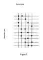
- FIG. 2 shows a cross connection arrangement in which each subscriber line has four different connection paths (S1-D1, S1-D2... S1-D8, S2-D1 S2-D3 ??S2-D8) to connect with four of the eight DSLAM port lines.
- Some of the DSLAM port lines are connected to only one of the two shown subscriber lines e.g. D2, D3, D4.
- Other DSLAM port lines are connected to both of the two subscriber lines D1, D8.
- the arrangement provides a 4x expansion for each subscriber line.
- FIGS 3a and 3b show two alternative possible implementations of the present invention using relay contact switches which can be used at the crosspoints of the embodiments of the present invention.
- switches could be used in any embodiment, e.g. electromechanical or semiconductor switches.
- Latching relays are preferably used in order to preserve the switching state when power is removed. Switching of the relays will be under the control of a controller, e.g. microcontroller which may be onboard or remote. In order to save power, relay operations will be done sequentially, i.e. power will only ever be applied to one relay at a time. Switching an individual relay takes of the order of 5ms, so an entire relay of 100 relays can be refreshed in less than 1s.
- Figures 3a and 3b show two possible arrangements for an expansion of four for a single subscriber line with four DSLAM lines.
- Figure 5 A similar illustration to Figure 4 is shown in Figure 5 , also with an expansion factor of two. In this example however, there are ten subscriber lines and five service ports.
- Service Port Blocking all service ports are used, and no further service can be granted.
- the only de-blocking option here is to install more service ports, together with another matrix to connect the subscribers to them.
- the present invention has as an object to delay this moment as long as possible.
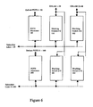
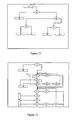
- Figures 6 and 7 shows examples of systems and communications architectures which can be used to implement the present invention.
- Figure 6 shows a switch matrix of two rows of switch modules 100-102, 200-202. The dashed lines indicate that the matrix can be expanded in the horizontal and/or vertical direction.
- Fifty subscriber lines are each connected to POTS disconnect switches 100, 200. These switches 100, 200 are provided to allow each subscriber to be connected to its respective default POTS port. A relay contact (not shown) on the switches 100, 200 for each subscriber line is provided to connect each line through to its default POTS connection.
- Each switch 100, 200 is respectively connected to corresponding cross connection switch cards 101, 102, 201, 202.
- Switch cards 101, 102 provide connection for subscriber lines 1-50 and switch cards 201, 202 provide connection for subscriber lines 51-100.
- Cross connection switch cards 101, 201, and 102, 202 are respectively connected to DSLAM transmission lines 1-24 and 25-48.
- switches 100 and 101 Fifty subscribers would be connected to twenty-four DSLAM ports. On the addition of switch 102, fifty subscribers could be connected to forty-eight DSLAM ports. On the addition of the bottom row, one hundred subscribers could be connected to forty-eight DSLAM ports.
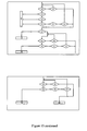
- FIG. 7 shows a proposed communications architecture in which the switch cards are connected together by means of a serial bus (e.g. RS485), under the control of a master controller card 300.
- This master control card 300 controls the configuration of each of the switches, and the switch cards determine their address, and hence their position in the matrix, from pins on the backplane connector (provides connectivity between individual elements of the system) into which they are plugged.
- a cross-connect arrangement or a concentrator connects specific, idle inputs/outputs to arbitrary, idle inputs/outputs.
- concentrators where one number of inputs/outputs N is greater than the other number of inputs/outputs M are mainly of interest.
- the topology of the switching matrix is irregular.
- a switching matrix is said to be irregular if input-output connections can have different delays, where delay is defined as the number of switching elements through which the signal must pass.
- delay is defined as the number of switching elements through which the signal must pass.
- the present invention concerns an irregular R-stage switching matrix with R equal to or greater than 3 and will be described for example only with respect to 3 and 4 stage switching matrices.
- the cross-connect arrangements according to the present invention having N first inputs/outputs that are to be connected to any of M second input/outputs, and the total number of switches is less than N x M.
- Fig. 8 shows a 4-stage switching matrix in accordance with an embodiment of the present invention with stages 26-29.
- the matrix comprises on the left hand side of the figure N horizontal conductive lines terminated by first inputs/outputs and M vertical conductive lines terminated by second inputs/outputs. Reference to horizontal and vertical lines applies only to the figure - it is not intended that the words horizontal or vertical refer to the physical arrangement of the lines.
- switching elements are provided in accordance with a particular scheme.
- the subscriber inputs 20 are shown on the left and the service outputs 22 (e.g. xDSL) are shown on the left at the top.
- the crosspoints 24 of the first stage 26 are switching elements through which the outputs are directly reachable from the inputs.
- all inputs 20 of the first stage 26 have at least the same number "a" of crosspoints or switches 24.
- Some of the lines in Fig. 8 have 2 switches.
- Other lines have 3, e.g. input lines 65-96.
- the present invention is not limited to a constant number of switches per line and can be extended to a variable number of switches at crosspoints.
- the present invention also includes a first block of inputs 20 connected by horizontal lines to a first number of switches at crosspoints, e.g. 1 switch at a crosspoint per input and a second block has a second number of switches at crosspoints, e.g. more than 1 switch at a crosspoint per input as shown schematically in Fig. 9 .
- the ordering of the crosspoints in the second block of the first stage is not at random, but avoids repeating combinations in order to increase the connectivity of the switching matrix.
- a topology having a first stage comprising a first block 30 with 1 switch at a crosspoint per input 20 and second block 32 with 2 switches at crosspoints per input 20 as shown in Fig. 9 .
- inputs 20 belonging to the first block 30 are said to be class 1 inputs; inputs belonging to the second block 32 are said to be class 2 inputs.
- the 2 nd , 3 rd and 4 th stages 27-29 of the switching matrix are a means of connecting an arbitrary input of the first stage 26 to one of a part of the set of outputs 22 or the entire set of outputs 22.
- the second stage 27 has always one or more switches at crosspoints 25 on a first set of lines, e.g. the odd lines, and one or more switches at a crosspoints on a second set of lines, e.g. even lines, whereby the first and second set do not overlap.
- a first set e.g. the first half of the outputs 22 is reachable through the third and fourth stages 28 and 29.
- a second set e.g. the second half, of the outputs 22 is reachable through the third and fourth stages 28 and 29 (see Fig. 10 ).
- the outputs 22 are reachable through the first stage 26 directly for some of the inputs 20 and also outputs 22 are reachable from the fourth stage 29 via the second and third stages 27, 28.
- the inputs 20 have access to the outputs 22.
- a controlling means which may be located anywhere, e.g. with the cross-connect or somewhere else in the telecommunications network, i.e. remote controlling means, first checks the possibility to route the specified input 20 to an output 22 directly through the first stage 26.
- the controlling means tries first of all to find a way through the second to fourth stages 27-29 to reach an idle output 22. If this is not possible, the controlling means can attempt a rearrangement of the matrix, i.e. try to reroute the connection paths by altering the switches along those paths.
- a routing policy in accordance with an embodiment of the present invention will be described with reference to the embodiments described with reference to figures 8 to 11 .
- the present invention is not limited to four stage switching matrices and can be applied to any R-stage matrices where R is equal to or greater than 3.
- the controlling means can be implemented by software running on a suitable computing device, e.g. a personal computer or a workstation.
- the software is provided with code for detecting connection requests. Furthermore the software runs initially on an internal database. When a solution is found, the physical connection is performed. This approach makes a make-before-break strategy possible. This means that whenever a rearrangement of an existing connection should be performed, first a parallel connection is made before breaking the original one.
- an input for which the connection request arrives is designated as input A.
- the controlling means starts the search for an output to which the specific input can be connected.
- the routing policy comprises the following steps:
- a set of 25 inputs is selected none of which can be connected to 7 of the 25 outputs. If a connection request arrives for this set of inputs, independent of the order, at least 7 inputs will be blocked for this concentrator, no matter how intelligent the control algorithm. Another property is that the blocking can possibly occur before a reasonable number of connection requests has been made, e.g. before the 19 th connection request. The appearance of blocking in a little employed switching matrix is unacceptable. In the following simulation results will be discussed, proving the quasi-non-blocking property of the current invention.
- the present invention also includes a telecommunications network apparatus as hereinbefore described with reference to Figures 2 to 15 or a telecommunications network system as hereinbefore described with reference to Figures 2 to 15 .
- the present invention also includes a method of adapting an in situ telecommunications network apparatus as hereinbefore described with reference to Figures 2 to 15 .
- Stubs cause a degradation in frequency performance of the circuit and, in fact, the number and characteristics of the stubs attached to a particular live circuit varies as other subscribers are connected or disconnected, and this change in electrical characteristic can be enough for the line to drop out of service. Accordingly, a design that reduces the number or size of stubs is a significant benefit.
- the second to at least third stages of the cross-connect device according to the present invention as well as the controller may be supplied as separate modules which may be used to upgrade an existing installation.
Description
- The present invention relates to a method and apparatus for rearranging connections between a multitude of transmission lines for providing telecommunications services especially to the provision of a permanent new service such as xDSL. Preferred embodiments relate to a method and apparatus for rearranging connections between a first and a second set of lines, e.g. subscriber and service transmission lines.
- Traditional telephony systems have relied on a combination of automatic (for example Strowger) and manual (cross-connect jumpering, i.e. using jumper cables to connect) methods to provide a continuous metallic path between two telephone users, so that a conversation could take place.
- More recently, electronic switching has replaced some of this connectivity function, specifically for individual telephone conversations, but there has continued to be a requirement for connecting and disconnecting individual pairs of wires at various 'flexibility points' such as street cabinets and exchanges, so that only the pairs of wires connected to subscribing customers are connected to the (expensive) electronic switches.
- This remaining connectivity function is still predominantly carried out manually, and there is significant interest in automating the process (e.g.
WO01/20922 US6710268 ,US4833708 ,US2001/0030521 ,US6265842 ,US6253071 andUS5456608 ). However the high cost of automatic systems has prevented their widespread deployment. - Taking a specific prior art example as outlined in
WO01/20922 - One problem is that it becomes desirable sooner or later to rearrange the connections of certain conductors to the local exchange. For instance, a subscriber may have purchased a broadband service and needs to be connected to an ISDN (Integrated Services Digital Network) line interface board instead of to a conventional PSTN (Public Switched Telephone Network) line interface board. Although this rearrangement can be effected manually in the MDF, it necessitates a visit to the access node, i.e. the location in which the MDF is placed.
- In order to avoid visiting the access node each time a rearrangement is required, a Metallic Cross-Connect (MXC) is placed between the MDF and the local exchange (or could replace the MDF). The MXC includes a large number of connection points, so called cross-points, arranged in connection matrices, and enables remotely controlled reconnections of connected conductors. A very large number of cross points are required to achieve a coupling that is totally free from congestion, and consequently the MXCs are expensive.
- Cross-connects are not solely used in the access network. Digital cross-connects, (DXC) and optical cross-connects (OXC) are used in the transport network to enable conductors to be reconnected between transmission equipment.
- As indicated above, the prior art cross-connects have a very large number of cross points as they are arranged to allow the connection of every subscriber transmission line to every service transmission line port (e.g. POTS (Plain Old Telephone Service) port, ADSL Asymmetric Digital Subscriber Line port, DSLAM (Digital Subscriber Line Access Multiplexer) port, ISDN port) in a "any to any" switching relationship i.e. full connectivity.
- Concentrators are known, in which inputs are connected to arbitrary outputs by means of switch elements. Concentrators are in common use in central offices and street cabinets of a telephone network.
- Attempts have been made to reduce the total number of switches at crosspoints of the matrix and by consequence reduce the overall cost of the concentrator. Most of those topologies use sparse crossbars in which the connections to subscribers do not all have corresponding connections towards all of the network connections. This relies on not all subscribers wanting the service at the same time. The main problem which arises when reducing the total number of switch elements is the increasing blocking probability. In telephone switching systems blocking is annoying but the system can be deblocked by users terminating calls. However, when permanent service connections are to be made this form of deblocking is not very suitable.
-
US 4,750,202 describes an optimum way of connecting services when using a sparse crossbar switching arrangement. It is said to be non-blocking but in fact the switching arrangement will block with some certainty, e.g. only 9 calls placed by random selection from 125 subscribers may be switched through 25 outputs without blocking, when each input line is connectable to one of five of the output lines. -
EP 1549102 describes a method and apparatus for a non-blocking multistage optical switch using crosspoint switches for performing group switching in DWDM optical networks. One embodiment is an N x N three-stage group connector with N inputs and N outputs, wherein the N outputs are divided into r output groups, each group including n outputs such that r = N / n. The group connector comprises a first stage comprising r n x m crossbar switch modules, wherein m is greater than or equall to n-1; a second stage comprising m r x r crossbar switch modules; and a third stage comprising r M x N concentrator switch modules. The switches used are any-to-any switches requiring a very large number of individual switches. - It is the objective of this invention to provide a solution that has a comparatively low cost of ownership, and therefore justifies the automation of the majority of the remaining manual processes.
- In a first aspect the present invention provides a cross-connect device: comprising a plurality of first transmission path inputs/outputs (N) and a plurality of second transmission path inputs/outputs (M), a remotely actuated cross connection arrangement to remotely connect selective first transmission path inputs (N) to selective second transmission path inputs (M), and a controller for the remotely actuated cross connection arrangement, the controller being adapted to execute a deblocking algorithm.
- The present invention also provides a cross-connect device having a plurality of N first transmission path input/output terminals and a plurality of M second transmission path input/output terminals, the device having a remotely actuated cross-connection arrangement comprising:
- a first sparse cross-bar arrangement having first connection lines connected to the plurality of first transmission path input/output terminals and second connection lines connected to the plurality of second transmission path input/output terminals and a plurality of first switch elements for connecting selective ones of the first connection lines to selective ones of the second connection lines,
- a second sparse cross-bar arrangement having third connection lines connected to at least some of the first connection lines, and fourth connection lines and a plurality of second switch elements for connecting selective ones of the third connection lines to selective ones of the fourth connection lines, and
- at least a third sparse cross-bar arrangement having fifth connection lines connected to at least some of the fourth connection lines, and sixth connection lines and a plurality of third switch elements for connecting selective ones of the fifth connection lines to selective one of the sixth connection lines, the device having selectable connection paths between the sixth connection lines and at least some of the second transmission path input/output terminals, whereby the total number of switching elements for the at least first to third sparse cross-bar arrangements is less than N x M. Reduction in the number of switching elements below N x M has the advantage of cost savings while still maintaining a non-blocking cross-connect device.
- The above cross connection arrangement comprises a plurality of connection paths between the first transmission path inputs/outputs (N) and second transmission path inputs/outputs (M) which can be selectively remotely actuated to cross connect a selective first transmission path input/output to a selective second transmission path input/output, and wherein the number of connection paths in the first sparse crossbar represent a percentage less than 50% of full connectivity.
- At least a fourth sparse cross-bar arrangement can also be provided having seventh connection lines connected to at least some of the sixth connection lines, and eighth connection lines and a plurality of fourth switch elements for connecting selective ones of the seventh connection lines to selective ones of the eighth connection lines, the eighth connection lines being connected to at least some of the second connection lines, whereby the total number of switching elements of the first to fourth sparse cross-bar is less than N x M. The addition of a fourth sparse cross-bar provides additional switching possibilities which helps to obtain a non-blocking cross-connect.
- Preferably, in the cross-connect device the total number of switching elements is less than 50%, less than 40%, less than 30%, or less than 20% of N x M. The present invention based on the surprising finding that with a low number of switches arranged in a switching matrix comprising R stages where R is greater than or equal to 3, a substantially non-blocking functionality can be obtained.
- In the switching matrix there can be S third lines and T fourth lines, U fifth lines and V sixth lines and the relationships between N, M, S, T, U, and V are:
- S is less than or equal to N,
- T is less than or equal to S,
- U or V are less than or equal to T.
- If a fourth stage is added there are W seventh lines and X eighth lines, and W and X are less than or equal to T.
- In addition, S can be less than N and for the first connection lines which are not connected to the second sparse cross-bar arrangement, connections to the second transmission path input/output terminals is only possible using the first switching elements. This has the advantage that for a certain number of inputs, there is already a possible output and the number of switches in the first stage is lower.
- One design rule which can be of advantage is that the second sparse cross-bar arrangement has first and second non-overlapping sets of fourth connection lines and each third connection line can be connected to a fourth connection line in either the first or second sets by the second switching elements. This improves the ability to find and connect to an idle output.
- Another design rule is that the third and fourth sparse cross-bar arrangements (if present) are adapted so that a fourth connection line from the first set can be connected to a third set of the second transmission path input/output terminals and a fourth connection line from the second set can be connected to a fourth set of the second transmission path input/output terminals. Again this improves the possibility of obtaining a connection between the inputs and outputs.
- Preferably, the device is adapted to implement a non-blocking rerouting by an automatic process. This allows remote switching and deblocking.
- The non-blocking rerouting can be by rearrangement. By allowing rearrangement of which switches are activated, the opportunities to make a through connection are increased.
- The rearrangement can be a chain of rearrangements. For instance multiple switches may be deactivated/activated in order to rearrange the switching matrix.
- The device may be arranged to bridge the connection between a subscriber terminal and a telecommunications service. For example, one or more of the first transmission path input/output terminals can be arranged to provide connection to subscriber transmission lines and the one or more of the second transmission path input/output terminals can be arranged to provide connection for service transmission lines.
- In another aspect the present invention provides a method of adapting in situ a telecommunications network apparatus, the apparatus having a plurality of N first transmission path input/output terminals and a plurality of M second transmission path input/output terminals, and a remotely actuated cross-connection arrangement comprising:
- a first sparse cross-bar arrangement having first connection lines connected to the plurality of first transmission path input/output terminals and second connection lines connected to the plurality of second transmission path input/output terminals and a plurality of first switch elements for connecting selective ones of the first connection lines to selective ones of the second connection lines,
- a second sparse cross-bar arrangement having third connection lines connected to at least some of the first connection lines, and fourth connection lines and a plurality of second switch elements for connecting selective ones of the third connection lines to selective ones of the fourth connection lines, and
- at least a third sparse cross-bar arrangement having fifth connection lines connected to at least some of the fourth connection lines, and sixth connection lines and a plurality of third switch elements for connecting selective ones of the fifth connection lines to selective one of the sixth connection lines, the arrangement having selectable connection paths between the sixth connection lines and at least some of the second transmission path input/output terminals, the method comprising:
- activating a first switching element to provide a first connection path between a first transmission path input/output terminal and a second transmission path input/output terminal,
- and if this is not possible, activating selective ones of the second to at least third switching elements to provide a second connection path between a first transmission path input/output terminal and a second transmission path input/output terminal.
- Another rerouting step could be: determining if there is an idle second transmission path input/output terminal and if so, determining if this idle second transmission path input/output terminal can be connected to a busy first transmission path input/output terminal through a third connection path of the cross-connection arrangement, and if so rearranging the busy first transmission path input/output terminal to be connected to the idle second transmission path input/output terminal via the third connection path followed by activating selective ones of the first to at least third switching elements to provide the first or second connection path between a first transmission path input/output terminal and a second transmission path input/output terminal. A first connection path represents a connection made through the first sparse crossbar; a second connection path represents a connection made through the second and at least third sparse crossbar.
- Another rerouting step can be: selecting a busy a first transmission path input/output terminal and de-selecting the first switching element which provides the connection of the busy first terminal to a busy second transmission path input/output terminal, and activating another first switching element to provide a connection path between the busy first transmission path input/output terminal and another idle second transmission path input/output terminal, and activating a first switching element to provide the first connection path between a first transmission path input/output terminal and a second transmission path input/output terminal, and, if this is not possible, activating selective ones of the second to at least third switching elements to provide a second connection path between a first transmission path input/output terminal and an idle second transmission path input/output terminal.
- If the previous steps have failed, a further rerouting step can be determining if there is an idle second transmission path input/output terminal and if so, determining if this idle second transmission path input/output terminal can be connected to a busy first transmission path input/output terminal through a third connection path, and if so rearranging the busy first transmission path input/output terminal to be connected to the idle second transmission path input/output terminal via the third connection path followed by activating selective ones of the first to at least third switching elements to provide the first or second connection path between a first transmission path input/output terminal and a second transmission path input/output terminal.If these previous steps have failed, a further rerouting step can be selecting a busy a first transmission path input/output terminal and de-selecting the first switching element which provides the connection of the busy first terminal to a second transmission path input/output terminal, and activating second and at least third switching elements to provide the connection path between the busy first transmission path input/output terminal and a second transmission path input/output terminal, followed by
activating selective ones of the first to at least third switching elements to provide the first or second connection path between a first transmission path input/output terminal and a second transmission path input/output terminal. - Providing the first or second connection includes a chain of rearrangements in which more than one rearrangement of the activation of switching elements is carried out in the second sparse cross-bar.
- The present invention also provides a computer program product comprising code segments for carrying out any of the methods of the present invention. The computer program product can be stored on a machine readable storage medium such as a hard disk, diskettes, tape storage media, optical disks such as CD-ROM or DVD-ROM, solid state memory, etc.
- The present invention also includes a telecommunications system comprising a device according to the present invention or which implements a method according to the present invention.
- With full connectivity being defined by NxM connection paths, the present invention provides substantially less connection paths but still provides a high probability of connection between the first and second inputs, given the comparatively small number of cross connections required at the outset and also over a period of time following initial installation of the network apparatus.
- In preferred embodiments, the number of switching elements may represent any one percentage less than 50% of the number of switch elements required for full connectivity (i.e. les than 49, 48, 47 .... 3, 2, 1) in a single crossbar arrangement. Preferably, the number of switching elements may represent a percentage between 50 and 5, 50 and 10, 50 and 15, 50 and 20, 45 and 20, 40 and 20, 35 and 20, 30 and 20, or 25 and 15 % of the number of switching elements required for full connectivity in a single crossbar arrangement. Preferably, the number of switching elements may represent a percentage between 40 and 5, 40 and 10, 40 and 15, 35 and 15, 30 and 15, 25 and 15, or 25 and 20 % of the number of switching elements required for full connectivity in a single crossbar arrangement. Preferably, the number of connection paths may represent a percentage between 30 and 5, 30 and 10, 30 and 15, 25 and 15 of the number of switching elements required for full connectivity in a single crossbar arrangement.
Although a less than NxM number of connection paths can lead to a blocking arrangement as more and more of the connection paths are used to connect first and second inputs (N, M), any blocks can be subsequently unblocked automatically by the methods of the present invention or they may be manually unblocked during routine service visits. The present invention provides a surprising practical solution which is not as expensive as a corresponding fully connected network apparatus, and which can progressively be configured to be adapted to provide protection paths and, in the meantime, provide a service which has a high probability of providing cross connections. - In addition to the automatic rerouting processes of the present invention the connection arrangement may be deblocked by manual jumpering (i.e. use of jumper cables to connect) of one or more inputs/outputs (N, M) to alternative (N, M) inputs/outputs.
- Preferably, the network apparatus is arranged to bridge the connection between a subscriber terminal and a telecommunications service. Preferably, one or more of the first inputs/outputs (N) are arranged to provide connection to subscriber transmission lines. One or more of these subscriber transmission lines may be arranged to connect to a subscriber terminal such as a computer, a phone, a television or other electronic device. Preferably, on or more of the second inputs/outputs (M) are arranged to provide connection for service transmission lines. These service transmission lines may be arranged to provide broadband, POTS, ISDN, DSL (Digital Subscriber Line), ADSL, or other telecommunications services.
- One, more or all of the first inputs/outputs could be at a subscriber end or service end of a telecommunications network. One, more or all of the second inputs/outputs could be at a subscriber end or service end of a telecommunications network.
- In a specific embodiment, one, more or all the second input/output terminals are arranged to be connected to one or more DSLAM connection ports.
- The cross-connect device may also comprise one or more other connection paths which are "hard-wired" or which provide permanent connection, and thus are not required to provide actuated connection. Furthermore, one or more of the connection paths may be arranged to be non-remotely actuated. One or more of the connection paths may be arranged to be both remotely and non-remotely actuated.
- The device may be adapted to be used in a wired telecommunications system. The network apparatus may be adapted to be used in a wireless or optical telecommunications system. For example, one, more or all of the first and second inputs/outputs (N, M) may be adapted for conductive transmission path technology. One, more, or all first and second inputs/outputs (N, M) may be adapted for optical transmission path technology. One, more or all the connection paths may be conductive transmission paths. One, more or all connection paths may be optical transmission paths.
- Preferably, the device is arranged to be used in an access network. Preferably, the device is arranged to be used in a transport network to enable connection to transmission equipment.
- The device may comprise a linear and/or rotary motor drives to enable the automation of the cross connection arrangement, e.g. to switch the switching elements selectively.
- The device may be a MDF. The device may also be a street cabinet. The device may be arranged to be part of the local exchange.
- Preferably, each connection path is provided by a number of switching elements, the cross connection arrangement being adapted to provide between two and ten, more preferably four, switching options for each first input/output (N).
- It has unexpectedly been found that acceptably low risk of blocking can be achieved with the relatively low numbers of connection options, i.e. three or more interlinked sparse cross-bars, according to the present invention, especially surprisingly with the preferred 2 to 10 (especially 4) switching connection options, and this leads to commercially significant advantages.
- Preferably, the cross connection device is comprised in a switch card arranged to be connectable to one or more switch cards.
- Preferably, the cross connection device is comprised in a switch card arranged to be connectable to one or more service transmission lines.
- Preferably, the cross connection device is comprised in a switch card arranged to be connectable to one or more subscriber transmission lines.
- In another aspect the present invention provides a method of adapting in situ a telecommunications network apparatus by adding additional stages of sparse cross-bars according to the present invention. Each of these sparse cross-bars comprise one or more self-contained cross connection arrangement modules, each of these modules providing less than 50% connectivity.
- Embodiments of the present invention will be described, by way of example, with reference to the following figures in which :
-
Figure 1 is a block diagram illustrating an arrangement for reconnecting conductors in an access network by remote control in accordance with known technology; -
Figure 2 illustrates a basic architecture of a sparse crossbar in accordance with the present invention; -
Figures 3a and 3b illustrate an arrangement according to the present invention using relay switches; -
Figure 4 shows an arrangement according to the present invention, which can be viewed as a sub-equipped (non-full connectivity) crossbar switch (sparse crossbar); -
Figure 5 shows an arrangement according to the present invention, which can be viewed as a sub-equipped (non-full connectivity) crossbar switch (sparse crossbar) to illustrate blocking. -
Figure 6 shows a system architecture which can be used to implement the present invention; -
Figure 7 shows a communications architecture which can be used to implement the present invention. -
Figure 8 shows a non-blocking 4-stage cross-connect in accordance with an embodiment of the present invention. -
Figure 9 shows a further non-blocking 4-stage cross-connect in accordance with an embodiment of the present invention. -
Figure 10 shows that in a cross-connect according toFig. 8 from an uneven fourth line there are connections paths to the first 16 of the second lines and from an even fourth line there are connection paths to the second 16 of the second lines. -
Figure 11 shows a 3-stage cross-connect in accordance with an embodiment of the present invention. -
Figures 12 and 13 show a re-routing method flow in accordance with an embodiment of the present invention. -
Figure 14 shows an embodiment of a chain of arrangements of a cross-connect in accordance with the present invention. -
Figures 15 and16 show a cross-connect according to the present invention and a prior art device which are used for comparison purposes. - The present invention will be described with respect to particular embodiments and with reference to certain drawings but the invention is not limited thereto but only by the claims. Any reference signs in the claims shall not be construed as limiting the scope. The drawings described are only schematic and are nonlimiting. In the drawings, the size of some of the elements may be exaggerated and not drawn on scale for illustrative purposes. Where the term "comprising" is used in the present description and claims, it does not exclude other elements or steps. Where an indefinite or definite article is used when referring to a singular noun e.g. "a" or "an", "the", this includes a plural of that noun unless something else is specifically stated.
- Furthermore, the terms first, second, third and the like in the description and in the claims, are used for distinguishing between similar elements and not necessarily for describing a sequential or chronological order. It is to be understood that the terms so used are interchangeable under appropriate circumstances and that the embodiments of the invention described herein are capable of operation in other sequences than described or illustrated herein.
- Moreover, the terms top, bottom, over, under and the like in the description and the claims are used for descriptive purposes and not necessarily for describing relative positions. It is to be understood that the terms so used are interchangeable under appropriate circumstances and that the embodiments of the invention described herein are capable of operation in other orientations than described or illustrated herein.
- Although transmission lines are often formed from electrical conductors, the present invention is also applicable to systems incorporating wireless or optical transmission technology (e.g. radio frequency wireless or fibre optics). In such cases, the sparse crossbars include wireless or optical switches at crosspoints. However, for convenience, the foregoing description will primarily focus on conductor transmissions systems for illustration purposes only.
- In the following reference will be made to stages of a cross-connect, each stage being a sparse crossbar. Although these are shown in drawings as separate crossbars, any topology which implements the present invention is included within the scope. Accordingly, the lines of the first and second stages, etc. can be interlaced or intercalated to form a single large switching matrix in which however, the individual sparse cross-bars can still be identified from the logic of operation.
- In the following description reference will be made to "inputs" and "outputs". This is only for clarity purposes. Due to the fact that usually bidirectional transmission is possible an input can also be an output, i.e. it can be an input/output device or terminal. Wherever the word input is used it may be replaced with input/output (I/O) or I/O terminal.
- The term "switch" or "switching element" should be construed broadly. The present invention is not considered to be restricted to or limited by any particular type of switch. For example, the present invention includes any type of device which is able to make and break a connection such as reed switches, relays, especially latching relays, and also simple conductive pegs which are located in holes by means of a robot device, optical switching devices, e.g. electrically operated mirror deflecting devices, or similar.
-
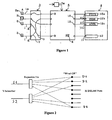
Figure 1 illustrates an arrangement for switching conductor connections in an access network by remote control with known technology. A number of twin-cables 1 are connected at one end tosubscriber equipments 2 and at the other end to anMDF 3 belonging to alocal exchange 4. Eachcopper twin cable 1 is connected via the MDF to an MXC (Metallic Cross Connect) 5, which is a cross connect that includes a large number ofcross points 6 and anoperating device 5a for setting cross points. The ports 8 to which the copper twin-cables are connected are connected toinputs 9 in the MXC byjumper cables 7 in the MDF. The MXC also includesoutputs 10 to whichinputs 11 for thelocal exchange 4 are connected. Several different types of communications services are associated with theinput 11 in the local exchange.Figure 1 shows symbolically that aninput 11a is associated withequipment 12a adapted for PSTN, that aninput 11b is associated withequipment 12b adapted for ISDN, and that aninput 11c is associated withequipment 12c adapted for ADSL. - The purpose of the
MXC 5 is to enable thecopper twin cables 1 to be reconnected to theinputs 11 by remote control. For instance, assume that a subscriberA having equipment 2a is originally a PSTN subscriber. A copper twin cable 1a is connected at one end to thesubscriber equipment 2a and at the other end to theinput 11a of the local exchange4, via theMDF 3 and theMXC 5. Also assume that the subscriber A changes the type of subscription by purchasing an ISDN service. Thesubscriber equipment 2a must then be connected to equipment in thelocal exchange 4 that is adapted for ISDN. Reconnection of the cable 1a to theinput 11b can be effected by remote control in theMXC 5, by resetting a number of cross points with the aid of the operating device. - Embodiments of the present invention provide a modified and improved cross connection compared to the prior art. Any of the cross connection arrangements described with respect to the present invention can be used in the
MXC 5, thelocal exchange 4, theMDF 3, or street cabinets (not shown). -
Figure 2 shows two subscriber lines (S1, S2) on the left hand side for connection with eight DSLAM port lines (D1-D8) on the right hand side. There are a corresponding number of inputs (N=2, M=8) for cross connection of each of the subscriber lines and DSLAM port lines. Typically however, there would be many more subscriber lines and DSLAM port lines. For example, in a typical street cabinet, there may be 300 subscriber lines and 120 DSLAM port lines. In a typical switch card there may be 50 subscriber lines and 24 service port lines. Due to the fact that not every subscriber may want an xDSL connection, there is an optimum number of subscriber lines that is in excess of the service port lines. -
Figure 2 shows a cross connection arrangement in which each subscriber line has four different connection paths (S1-D1, S1-D2... S1-D8, S2-D1 S2-D3 .....S2-D8) to connect with four of the eight DSLAM port lines. Some of the DSLAM port lines are connected to only one of the two shown subscriber lines e.g. D2, D3, D4. Other DSLAM port lines are connected to both of the two subscriber lines D1, D8. The arrangement provides a 4x expansion for each subscriber line. -
Figures 3a and 3b show two alternative possible implementations of the present invention using relay contact switches which can be used at the crosspoints of the embodiments of the present invention. However, other types of switches could be used in any embodiment, e.g. electromechanical or semiconductor switches. Latching relays are preferably used in order to preserve the switching state when power is removed. Switching of the relays will be under the control of a controller, e.g. microcontroller which may be onboard or remote. In order to save power, relay operations will be done sequentially, i.e. power will only ever be applied to one relay at a time. Switching an individual relay takes of the order of 5ms, so an entire relay of 100 relays can be refreshed in less than 1s. -
Figures 3a and 3b show two possible arrangements for an expansion of four for a single subscriber line with four DSLAM lines. -
Figure 4 shows an alternative illustration used to explain an expansion factor of two. Each subscriber line can be connected to two of the DSLAM lines, i.e. there is an expansion factor of 2. This figure shows certain principles of a sparse crossbar. The number of subscriber lines is large - at least as large as the number of DSLAM lines and usually considerably larger. To reduce the number of switches not every subscriber line can be connected to every DSLAM line - inFig. 4 there are only two switches per DSLAM line, i.e. there are two possibilities for connection of each subscriber line to DSLAM lines. This reduces the number of switches but has the disadvantage that, if for a particular subscriber line the corresponding two DSLAM lines have been already used for other subscribers, then there is no possibility of connecting the particular subscriber. The cross-connect is then blocked. How to prevent blocking will be described below. - Taking the aforementioned typical switch card example, conventional arrangements would have 50x24 (i.e. 1200) cross connection points. With an expansion factor of 4, i.e. four switches to DSLAM lines, the present invention would have 200 cross points. With the aforementioned typical street cabinet arrangement, there would be 300x120 (i.e. 36000) cross points. Again, with an expansion factor of 4, the present invention would have 1200 cross points. In an arbitrary example, if you consider a 10X10 matrix, the prior art would provide 100 cross points. With an expansions factor of 2, the present invention has 20 cross points.
- A similar illustration to
Figure 4 is shown inFigure 5 , also with an expansion factor of two. In this example however, there are ten subscriber lines and five service ports. - Two types of blocking can occur - blocking of the switch fabric itself, and blocking due to all service ports being used.
- The Switch Fabric is blocked when after a certain number of lines have been switched through, there are no more possibilities to reach an output line even though some of these are free.
- A first type of deblocking includes automatic rearrangement. This form of deblocking can be performed by a re-routing or deblocking algorithm in accordance with the present invention.
- A second type of deblocking involves manually patching a subscriber to another subscriber input of the switching matrix. This requires a visit and the present invention has an object to reduce such visits.
- A third type of blocking requires a new card: Install an expansion card giving each subscriber line more connection options, increasing "M". Again this requires a manual intervention. The present invention has as an object to delay this moment as long as possible.
- In the case of Service Port Blocking all service ports are used, and no further service can be granted. The only de-blocking option here is to install more service ports, together with another matrix to connect the subscribers to them. The present invention has as an object to delay this moment as long as possible.
-
Figures 6 and7 shows examples of systems and communications architectures which can be used to implement the present invention.Figure 6 shows a switch matrix of two rows of switch modules 100-102, 200-202. The dashed lines indicate that the matrix can be expanded in the horizontal and/or vertical direction. - Fifty subscriber lines are each connected to POTS disconnect
switches switches switches - Each
switch connection switch cards Switch cards switch cards connection switch cards - Each cross
connection switch card - If the switching matrix is required to handle more and more subscribers then more switches can be added in the vertical direction. If more DSLAM ports (or ports carrying another service) are required, then more cross connection switches can be added horizontally. As more and more cards are added, the overall size of the switch is increasing, rather than adding smaller switches. The possible connections for each subscriber line are spread across all the available DSLAM ports.
- So consider an apparatus which initially only comprised
switches switch 102, fifty subscribers could be connected to forty-eight DSLAM ports. On the addition of the bottom row, one hundred subscribers could be connected to forty-eight DSLAM ports. - It is possible to add further switch cards in parallel to increase the expansion. For example, an additional n=2 switch card can be added in parallel to an existing n=2 switch card. In other words, this additional switch card would be between the same POTS disconnect switch (i.e. subscriber lines) and the same DSLAM ports of the existing switch card. This additional switch card would be arranged to provide different connection options between the subscriber lines and the DSLAM ports to the existing switch card. This could involve adapting the connection paths in the existing switch card. In this way, the expansion would be increased to 4. This method could be used to add a different expansion to an existing expansion. (e.g. n=3 to n=2). Alternatively, the expansion provided by a switch card could be increased by providing a replacement switch card with a higher expansion (i.e. replacing an n=2 with an n=4).
-
Figure 7 shows a proposed communications architecture in which the switch cards are connected together by means of a serial bus (e.g. RS485), under the control of amaster controller card 300. Thismaster control card 300 controls the configuration of each of the switches, and the switch cards determine their address, and hence their position in the matrix, from pins on the backplane connector (provides connectivity between individual elements of the system) into which they are plugged. - The present invention also provides apparatus and methods for non-blocking cross-connects of the type described above, i.e. a cross-connect with means of connecting one of a plurality of inputs to a non-busy one of a plurality of outputs.
These embodiments can include: - i. The description of an R-stage irregular concentration switching matrix and method of operating the same, where R is an integer and is at least 3, and/or
- ii. Means and methods to control such a switching matrix, leading to a good non-blocking performance.
- These embodiments of the present invention include the operation of a rearrangeable, non-blocking cross-connect or concentrator. A switching matrix is said to be rearrangeable and non-blocking if the following is satisfied. Suppose connection requests arrive serially. Whenever a connection request arrives, the matrix is in a state where certain inputs are connected to certain outputs through the matrix. In the following a non-busy input or output is called an idle input or output. A switching matrix is defined as rearrangeable and non-blocking if every connection request can be satisfied, eventually by rescheduling the existing connections up to the point when a certain number of outputs are used. Ideally the switching matrix should only block when the number of outputs used is 100%. Such a cross-connect is known as a "wide sense non-blocking" device. However, in accordance with the present invention blocking at less than 100% is also an acceptable solution. For example, if for a cross-connect according to the present invention a random selection of any of 80% of the output ports can be assigned to an input port without blocking there is a considerable improvement over the crossbar of
US 4,750,202 which blocked after 9 from 25 service ports were allocated, i.e. after only 36% utilisation. - With a sparse crossbar, a connection between an input and an output need not be possible, despite the fact that neither of them is already connected. This situation occurs when the existing connections block all the possible routes between a specific input and an arbitrary output. In the context of a concentrator, rearranging the existing connections means finding a possible route between the requested set of inputs and an arbitrary set of outputs by altering the switch elements used in the sparse crossbar, so that every input is connected to a distinct output. After a rearrangement the set of inputs will be connected to another arbitrary set of outputs. The switching matrix can be operated in a make-before-break strategy. In other words, whenever a line should be rescheduled, a path between the input in question and an idle output can be made, before the original connection can be broken.
- A cross-connect arrangement or a concentrator connects specific, idle inputs/outputs to arbitrary, idle inputs/outputs. Obviously, concentrators where one number of inputs/outputs N is greater than the other number of inputs/outputs M are mainly of interest. In the present invention the topology of the switching matrix is irregular. A switching matrix is said to be irregular if input-output connections can have different delays, where delay is defined as the number of switching elements through which the signal must pass. By using an irregular switch topology, the total number of cross points, i.e. switches, is reduced. By applying an intelligent routing algorithm and an R-stage switching matrix, the non-blocking property is obtained.
- Topology of a switching matrix in accordance with embodiments of the present invention
- The present invention concerns an irregular R-stage switching matrix with R equal to or greater than 3 and will be described for example only with respect to 3 and 4 stage switching matrices. The cross-connect arrangements according to the present invention having N first inputs/outputs that are to be connected to any of M second input/outputs, and the total number of switches is less than N x M.
Fig. 8 shows a 4-stage switching matrix in accordance with an embodiment of the present invention with stages 26-29. The matrix comprises on the left hand side of the figure N horizontal conductive lines terminated by first inputs/outputs and M vertical conductive lines terminated by second inputs/outputs. Reference to horizontal and vertical lines applies only to the figure - it is not intended that the words horizontal or vertical refer to the physical arrangement of the lines. At a certain number of the crosspoints of the horizontal and vertical lines switching elements are provided in accordance with a particular scheme. Thesubscriber inputs 20 are shown on the left and the service outputs 22 (e.g. xDSL) are shown on the left at the top. Thecrosspoints 24 of thefirst stage 26 are switching elements through which the outputs are directly reachable from the inputs. In an embodiment of the present invention allinputs 20 of thefirst stage 26 have at least the same number "a" of crosspoints or switches 24. Some of the lines inFig. 8 have 2 switches. Other lines have 3, e.g. input lines 65-96. The present invention is not limited to a constant number of switches per line and can be extended to a variable number of switches at crosspoints. The present invention also includes a first block ofinputs 20 connected by horizontal lines to a first number of switches at crosspoints, e.g. 1 switch at a crosspoint per input and a second block has a second number of switches at crosspoints, e.g. more than 1 switch at a crosspoint per input as shown schematically inFig. 9 . The ordering of the crosspoints in the second block of the first stage is not at random, but avoids repeating combinations in order to increase the connectivity of the switching matrix. - In this embodiment a topology is shown having a first stage comprising a
first block 30 with 1 switch at a crosspoint perinput 20 andsecond block 32 with 2 switches at crosspoints perinput 20 as shown inFig. 9 . Furthermore,inputs 20 belonging to thefirst block 30 are said to beclass 1 inputs; inputs belonging to thesecond block 32 are said to beclass 2 inputs. The 2nd, 3rd and 4th stages 27-29 of the switching matrix are a means of connecting an arbitrary input of thefirst stage 26 to one of a part of the set ofoutputs 22 or the entire set ofoutputs 22. - In an embodiment of the present invention the
second stage 27 has always one or more switches atcrosspoints 25 on a first set of lines, e.g. the odd lines, and one or more switches at a crosspoints on a second set of lines, e.g. even lines, whereby the first and second set do not overlap. By making use of a line from the first set in thesecond stage 27, a first set, e.g. the first half of theoutputs 22 is reachable through the third andfourth stages second stage 27, a second set, e.g. the second half, of theoutputs 22 is reachable through the third andfourth stages 28 and 29 (seeFig. 10 ). The first and second sets ofoutputs 22 preferably do not overlap. As a result, if the second to fourth additional stages 27-29 are idle, every input of thesecond stage 27 can reach everyoutput 22 through the third andfourth stages - In the embodiments of the present invention shown in
Figs. 8 to 10 , theoutputs 22 are reachable through thefirst stage 26 directly for some of theinputs 20 and also outputs 22 are reachable from thefourth stage 29 via the second andthird stages elements 24 of thefirst stage 26 and thefourth stage 29 theinputs 20 have access to theoutputs 22. If a connection request arrives for a specifiedinput 20, a controlling means which may be located anywhere, e.g. with the cross-connect or somewhere else in the telecommunications network, i.e. remote controlling means, first checks the possibility to route the specifiedinput 20 to anoutput 22 directly through thefirst stage 26. If there is no possibility to make a direct connection through thefirst stage 26, then the controlling means tries first of all to find a way through the second to fourth stages 27-29 to reach anidle output 22. If this is not possible, the controlling means can attempt a rearrangement of the matrix, i.e. try to reroute the connection paths by altering the switches along those paths. - In
Fig. 11 another embodiment of the present invention is shown. In this case only threestages 26 to 28 are used. At thethird stage 28 outputs are connected to selected lines of thefirst stage 26, i.e. are chosen to select a line different from the lines that thisinput 20 in thefirst stage 26 could reach. Other details remain the same. This embodiment has the disadvantage of not having the additional lines made available by thefourth stage 29 in the previous embodiments but may use less switches. - A routing policy in accordance with an embodiment of the present invention will be described with reference to the embodiments described with reference to
figures 8 to 11 . However the present invention is not limited to four stage switching matrices and can be applied to any R-stage matrices where R is equal to or greater than 3. - A routing policy is illustrated in
Fig. 12 and Fig. 13 and is based on the following data structures. For every stage 26-29 an input matrix configuration as well as an output matrix configuration is stored. The input matrix configuration contains the following information: - ■ A dynamic part: for every input-line of the considered stage the data structure includes a parameter indicating the state of the specified input (idle or busy).
- ■ A static part: for every input-line of the considered stage the data structure comprises the position of the different switching elements.
- The output matrix contains for every output the following information:
- ■ A parameter indicating the state of the considered output (idle or busy)
- ■ If the considered output is busy, the output matrix contains a pointer to the input line to which the considered busy output is connected.
- The controlling means can be implemented by software running on a suitable computing device, e.g. a personal computer or a workstation. The software is provided with code for detecting connection requests. Furthermore the software runs initially on an internal database. When a solution is found, the physical connection is performed. This approach makes a make-before-break strategy possible. This means that whenever a rearrangement of an existing connection should be performed, first a parallel connection is made before breaking the original one. In the following, an input for which the connection request arrives, is designated as input A. When a connection request arrives (
Fig. 12 , state 100), the controlling means starts the search for an output to which the specific input can be connected. The routing policy comprises the following steps: - ■ In
step 200 the controlling means considers the possibility to connect the input directly to an idle output through thefirst stage 26. In order to do so, the controlling means checks the positions of the switchingelements 24 in thefirst stage 26 for input A. If the output corresponding to one of those positions is idle, input A can be connected to this output. - ■ If YES in
step 200, the connection through thefirst stage 26 will be executed (state 300). In this state the dynamic part of input matrix of the first stage26 as well as the first stage output matrix are updated. - ■ If
step 200 does not find an idle output, the algorithm proceeds to step 400. Step 400 controls if the input is aclass 1 input. If YES instep 400,step 410 is performed which rearranges an existing connection. Step 410 will be discussed later. If NO instep 400,step 420 is performed. - ■ Step 420 occurs when a direct routing of an input of
class 2 is not possible. An important feature of the present invention is the development of an intelligent routing algorithm, leading to the rearrangeable non-blocking property. Step 420 comprises a number of refinements (Fig. 13 ), used when a direct connection through thefirst stage 26 is not possible. The different refinements are ordered by increasing complexity. - ■ Step 421 controls if there is a connection path through the second, third and
fourth stages 26 to 29 leading to anidle output 24. Starting from a specific input ofclass 2, every possible connection path through theadditional stages 26 to 29 is tested on its output (busy or idle). If a connection path can be found, the connection is made and the corresponding input and output matrices are updated (step 700). If noidle output 24 can be reached through the second to fourth stages, the controlling means proceeds to step 422. - ■ Step 422 executes a rearrangement and comprises steps 422.1, 422.2, 422.3, 422.4, 422.5 and 422.6. In the following the rearrangement of
step 422 will be called a backward rearrangement. In step 422.1 an idle output is selected. Then the controlling means tests the possibility to connect a busy input, connected through the additional stages 27-29, to the selected idle output. - ■ If NO in step 422.1, step 422.2 controls the presence of another idle output. If YES in step 422.2, step 422.1 is performed for the next idle output. If NO in step 422.2, the controlling means proceeds to step 423.
- ■ If YES in step 422.1, the selected busy connection is disconnected, the data structures are updated and step 422.3 is executed. After the
backward rearrangement stages stage 1 . If YES in step 422.3, the data structures are updated and the connection is made (step 700). If NO in step 422.3, the controlling means proceeds to step 422.4. In step 422.4 the controlling means tests the possibility to connect input A to an idle output through stages 27-29. If NO in step 422.4, the original state ofstages - ■ Arriving in
step 423 means that there is no direct connection path through thefirst stage 26 towards an idle output, nor through the additional stages 27-29, nor exists the possibility to do a backward rearrangement and make a connection. Step 423 aims at changing the initial state of the switching matrix by changing the connection path of an existing connection, connected directly through thefirst stage 26. Step 423 selects a busy input ofclass 2, connected to an output through thefirst stage 26, and tests if the busy input can be reconnected to an idle output, again however through thefirst stage 26. In thefollowing step 423 will be called a "first stage rearrangement". If NO instep 423, step 424 tests the presence of another busy input ofclass 2. If YES instep 424 the next busy input ofclass 2 is selected and step 423 is repeated. If NO instep 424, the controlling means proceeds to step 430. If YES instep 423, the corresponding data structure is updated and the controlling means proceeds to step 425. - ■ Step 425 tests the possibility to connect input A directly through the
first stage 26. Since the state of thefirst stage 26 has been changed, this may be possible. If YES instep 425, the controlling means proceeds to step 700 - ■ Step 426 tests the possibility to connect an input A to an idle output through stages 27-29 in the new state of the switching matrix.. If YES in
step 426, the controlling means proceeds to step 700 where the data structure is updated and the connection is made. If NO instep 426, the controlling means proceeds to step 427. - ■ Step 427 has the same functionality as step 422: see description of
step 422. If YES instep 427 the controlling means proceeds to step 700 where the connection is made and the data structure is updated. If NO instep 427,step 428 restores the state beforestep 423 and step 429 tests the presence of other busy inputs directly scheduled through the first stage. If YES instep 429, the controlling means loops to step 423. If NO instep 429, the controlling means tested all possible ways to do a first stage rearrangement. At this point no solution has been found and the controlling means proceeds to step 430. - ■ In the former step, the controlling means tested the possibility to rearrange the first stage by selecting a busy input connected directly through the first stage. As for
step 423, the goal ofstep 430 is to change the initial state of the switching matrix by changing the connection path of an existing connection, directly connected through the first stage. Step 430 selects a busy input connected to an output directly through the first stage and tests the possibility to reconnect the selected busy input through stages 27 -29. In the following we call step 430 a "first stage-to-second stage rearrangement". If NO instep 430, step 431 tests the presence of another busy input and the same procedure (step 430) is repeated. If YES instep 430 the corresponding data structures are updated and the state of the switching matrix is changed. The controlling means proceeds to step 432 which tests the possibility to connect input A directly through thefirst stage 26. If YES in 432 the controlling means proceeds to step 700 where the connection is made and the data structures are updated. If NO instep 432 the control means proceeds to step 433 which tests the possibility to reach an idle output through the additional stages 27-29. If YES in 433 the controlling means proceeds to step 700 where the connection is made and the data structures are updated. If NO instep 433 the algorithm proceeds to step 434 which has the same functionality asstep 422. It concerns a backward rearrangement: see description above relating to step422. If YES instep 434, the connection is made and the corresponding data structures are updated. If NO instep 434,step 435 restores the state beforestep 430 after which step 436 checks the presence of another busy input. If YES instep 436, the controlling means loops to step 430. If finally all busy inputs ofclass 2 are tested and no solution has been found, the controlling means proceeds to step 437. - ■ Up to this point the controlling means tested the possibility to reach an idle output by changing the state of the
first stage 26, by changing the state of the stages 27-29 or by a combined change of the first and the rest of the stages 26-29. The transformation of the state involved however not more than the connection path of one busy input. Step 437 tests the possibility to perform a chain of rearrangements in the stages 27-29 and to connect finally input A with an idle output. This is useful for example in the following situation (seeFig. 14 ). Input A cannot reach an idle output through thefirst stage 26 and in thesecond stage 27 the outputs corresponding with the two switching elements are busy. The input which uses the first of those busy outputs will be called input P. Input P can not be rearranged, because the controlling means already tested this possibility (step 422). If the second switch element of input P is also busy, we call the input that occupies the corresponding output Q. These method steps are repeated until the controlling means finds an input with a second idle switch element. This final input is the final element of a chain. The controller tests the possibility to route this final input through the stages 27-29 using the idle switch element. If YES, then all the other connections of the chain can be rearranged too, starting with the penultimate element of the chain. In the following we will call a rearrangement of this type a chain of forward rearrangement, in which 'forward' indicates that the rearrangement procedure does not start at an idle output at the output side. Finally input A can be connected through the stages 27-29 using the switch element that was originally busy. If however the ultimate element of the chain cannot reach an idle output through the idle switch element, the same procedure can be repeated for the second switch element of input A. If a solution is found, the controlling means proceeds to step 700: the corresponding data structures are updated and the connections are made. If no success is reached the controlling means proceeds to step 438. - ■ If the chain of forward rearrangements of
step 437 did not have any success, the controlling means performs step 438 which has the same functionality as the first stage rearrangement of step 423 (description see above), followed by a chain of forward rearrangements. Step 438 tests the possibility to rearrange thefirst stage 26. If NO instep 438, step 439 tests the presence of another busy input. If YES instep 439, the controller loops to step 438. If NO instep 439, the algorithm proceeds to step 443. If YES in 438,step 440 is performed. Step 440 has the same functionality as step 437: it tries to perform a chain of forward rearrangements. IF YES instep 440, the corresponding data structures are updated and the connection is made. If NO instep 440, the state of the switching matrix beforestep 438 is restored instep 441. Step 442 tests the presence of other busy inputs. If YES instep 442, the controlling means loops to step 438. If NO instep 442, the controlling means proceeds to step 443. - ■ Step 443 has the same functionality as the first stage-to-second stage rearrangement of step 430 (description see above). If NO in
step 443, step 444 tests the presence of another busy input. If YES instep 444, the controller loops to step 443. If NO instep 444 the controlling means proceeds to step 800 which means input A is blocked. If YES instep 443,step 445 is performed. Step 445 has the same functionality of step 437 (description see above) and tries to execute a chain of forward rearrangements. If YES instep 445, the controller proceeds to step 700 - ■ Step 410 will now be considered. In this situation a
class 1 input is blocked. The busy input B which blocks input A has to be reconnected to another idle output. Output C, the only output to which input A can be connected, is presently connected to input B. The connection path of input B is removed from the data structure. At this point a connection path will be searched for inputB using steps step 410 is restored. If YES the data structure is updated and the connection of input A and B is performed. - Taking a specific prior art example as outlined in
US 4,750,202 (orEP 0 257 290 B1Fig. 16 . The position of the crosspoints is determined by the following formula rx2 + sx + t = y, where (r,s,t) is an input described in a 5-base system and (x,y) is an output in a 5-base system. By consequence this concentrator has q3 inputs and q2 outputs, or 125 inputs and 25 outputs. For this system a worst-case scenario is depicted inFig. 16 . A set of inputs is selected which cannot be connected to the indicated outputs. In the considered example a set of 25 inputs is selected none of which can be connected to 7 of the 25 outputs. If a connection request arrives for this set of inputs, independent of the order, at least 7 inputs will be blocked for this concentrator, no matter how intelligent the control algorithm. Another property is that the blocking can possibly occur before a reasonable number of connection requests has been made, e.g. before the 19th connection request. The appearance of blocking in a little employed switching matrix is unacceptable. In the following simulation results will be discussed, proving the quasi-non-blocking property of the current invention. - In order to validate the contentions, a simulator of the current invention has been built. For illustration purposes a concentrator with 100 inputs and 24 outputs was considered as shown in
Fig. 15 . For thisspecific design 1 000 000 simulations have been performed. An overview is given in Table 1 and Table 2.Table 1: performance concentrator Total Percentage Number of concentrators 1 000 000 Concentrators with success 998 650 99,87 Concentrators with blocking 1350 0,13 Connection requests 24 000 000 Connection requests with success 23 998 647 99,994 Connection requests blocked 1353 0,006 Table 2: first blocking Total Percentage Concentrators with blocking 1350 0,135 24th request blocked 1320 0,132 23rd request blocked 24 0,0024 22nd request blocked 5 0,0005 21st request blocked 1 0,0001 - For this specific design it appears from Table 1 that 99,994% of the connection requests can be fulfilled. When blocking occurs, the blocked connection is in 97,78% (1320/1350) the final connection request. Furthermore maximum 2 lines were blocked, however only in 0.0002% of all cabinets. Also it can be guaranteed that there is no blocking up to 20 requests. This compares very favourably with the blocking after the 9th request in the prior art system.
- The present invention also includes a telecommunications network apparatus as hereinbefore described with reference to
Figures 2 to 15 or a telecommunications network system as hereinbefore described with reference toFigures 2 to 15 . The present invention also includes a method of adapting an in situ telecommunications network apparatus as hereinbefore described with reference toFigures 2 to 15 . - It will be appreciated by the person skilled in the art that various modifications can be made without departing from the scope of the invention. For example, the expansion could be applied to the DSLAM (service ports) ends so that every DSLAM port is connected to an array of relays, the output of which are each connected to several subscriber lines. The electrical performance of the switching matrix apparatus is enhanced if the switch structure is 'reversed' so that each DSLAM port is connected to several subscriber lines, rather than vice versa. There are usually less DSLAM ports than subscriber lines, and it is a preferred if there are less un-terminated lines (stubs) hanging off each DSLAM or subscriber line. Stubs cause a degradation in frequency performance of the circuit and, in fact, the number and characteristics of the stubs attached to a particular live circuit varies as other subscribers are connected or disconnected, and this change in electrical characteristic can be enough for the line to drop out of service. Accordingly, a design that reduces the number or size of stubs is a significant benefit.
- The second to at least third stages of the cross-connect device according to the present invention as well as the controller may be supplied as separate modules which may be used to upgrade an existing installation.
Claims (23)
- A cross-connect device having a plurality of N first transmission path input/output terminals (20) and a plurality of M second transmission path input/output terminals (22), the device having a remotely actuated cross-connection arrangement characterised by:a first sparse cross-bar arrangement (26) having first connection lines connected to the plurality of first transmission path input/output terminals (20) and second connection lines connected to the plurality of second transmission path input/output terminals (22) and a plurality of first switch elements (24) for connecting selective ones of the first connection lines to selective ones of the second connection lines,
a second sparse cross-bar arrangement (27) having third connection lines connected to at least some of the first connection lines, and fourth connection lines and a plurality of second switch elements (25) for connecting selective ones of the third connection lines to selective ones of the fourth connection lines, and
at least a third sparse cross-bar arrangement (28) having fifth connection lines connected to at least some of the fourth connection lines, and sixth connection lines and a plurality of third switch elements for connecting selective ones of the fifth connection lines to selective one of the sixth connection lines, the device having selectable connecting paths between the sixth connection lines and at least some of the second transmission path input/output terminals (22), whereby the total number of switching elements for the at least first to third sparse cross-bar arrangements is less than N x M. - The cross-connect device of claim 1, further characterised by at least a fourth sparse cross-bar arrangement (29) having seventh connection lines connected to at least some of the sixth connection lines, and eighth connection lines and a plurality of fourth switch elements for connecting selective ones of the seventh connection lines to selective ones of the eighth connection lines, the eighth connection lines being connected to at least some of the second connection lines, whereby the total number of switching elements of the first to fourth sparse cross-bar is less than N x M.
- The cross-connect device according to claim 1 or 2 characterised in that the total number of switching elements is less than 50%, less than 40%, less than 30%, or less than 20% of N x M.
- The cross-connect device of any previous claim characterised in that there are S third lines and T fourth lines, U fifth lines and V sixth lines and the relationships between N, M, S, T, U, and V are:S is less than or equal to N,T is less than or equal to S,U or V are less than or equal to T.
- The cross-connect device according to claim 5, characterised in that there are W seventh lines and X eighth lines, and W and X are less than or equal to T.
- The cross-connect device according to claim 4 or 5, characterised in that S is less than N and for the first connection lines which are not connected to the second sparse cross-bar arrangement (27), connections to the second transmission path input/output terminals (22) is only possible using the first switching elements (24).
- The cross-connect device of any previous claim, characterised in that the second sparse cross-bar arrangement (27) has first and second non-overlapping sets of fourth connection lines and each third connection line can be connected to a fourth connection line in either the first or second sets by the second switching elements (25).
- The cross-connect device of claim 7, characterised in that the third and fourth sparse cross-bar arrangements (28, 29) if present are adapted so that a fourth connection line from the first set can be connected to a third set of the second transmission path input/output terminals (22) and a fourth connection line from the second set can be connected to a fourth set of the second transmission path input/output terminals (22).
- The cross-connect device according to any previous claim, characterised in that the device is adapted to implement a non-blocking rerouting by an automatic process.
- The cross-connect device according to claim 9, characterised in that the non-blocking rerouting is by rearrangement.
- The cross-connect device of claim 10, characterised in that the rearrangement is a chain of rearrangements.
- The cross-connect device according to any previous claim arranged to bridge the connection between a subscriber terminal and a telecommunications service.
- A cross-connect device according to any previous claim, characterised in that one or more of the first transmission path input/output terminals (20) are arranged to provide connection to subscriber transmission lines.
- A cross-connect device according to any of the previous claims, characterised in that one or more of the second transmission path input/output terminals (22) are arranged to provide connection for service transmission lines.
- A method of adapting in situ a telecommunications network apparatus, the apparatus having a plurality of N first transmission path input/output terminals (20) and a plurality of M second transmission path input/output terminals (22), and the device having a remotely actuated cross-connection arrangement comprising:a first sparse cross-bar arrangement (26) having first connection lines connected to the plurality of first transmission path input/output terminals (20) and second connection lines connected to the plurality of second transmission path input/output terminals (22) and a plurality of first switch elements (24) for connecting selective ones of the first connection lines to selective ones of the second connection lines,a second sparse cross-bar arrangement (27) having third connection lines connected to at least some of the first connection lines, and fourth connection lines and a plurality of second switch elements (25) for connecting selective ones of the third connection lines to selective ones of the fourth connection lines, andat least a third sparse cross-bar arrangement (27) having fifth connection lines connected to at least some of the fourth connection lines, and sixth connection lines and a plurality of third switch elements for connecting selective ones of the fifth connection lines to selective one of the sixth connection lines, the arrangement having selectable connecting paths between the sixth connection lines and at least some of the second transmission path input/output terminals (22), the method comprising:activating a first switching element (24) to provide a first connection path between a first transmission path input/output terminal (20) and a second transmission path input/output terminal (22),and if this is not possible, activating selective ones of the second to at least third switching elements to provide a second connection path between a first transmission path input/output terminal (20) and a second transmission path input/output terminal (22).
- The method of claim 15, further characterised by: providing as a routing option: determining if there is an idle second transmission path input/output terminal (22) and if so, determining if this idle second transmission path input/output terminal (22) can be connected to a busy first transmission path input/output terminal (20) through a third connection path, and if so rearranging the busy first transmission path input/output terminal (20) to be connected to the idle second transmission path input/output terminal (22) via the third connection path followed by activating selective ones of the first to at least third switching elements to provide the second connection path between a first transmission path input/output terminal (20) and a second transmission path input/output terminal (22).
- The method of claim 16, further characterised by: providing as a routing option, selecting a busy first transmission path input/output terminal (20) and selecting another first switching element (24) to provide the first connection to a second transmission path input/output terminal (22), and activating a first switching element (24) to provide the first connection path between a first transmission path input/output terminal (20) and a second transmission path input/output terminal (22),
and, if this is not possible, activating selective ones of the second to at least third switching elements to provide the second connection path between a first transmission path input/output terminal (20) and a second transmission path input/output terminal (22). - The method of claim 17, further characterised by: providing a routing option of determining if there is an idle second transmission path input/output terminal (22) and if so, determining if this idle second transmission path input/output terminal (22) can be connected to a busy first transmission path input/output terminal (20) through a third connection path, and if so rearranging the busy first transmission path input/output terminal (20) to be connected to the idle second transmission path input/output terminal (22) via the third connection path followed by activating selective ones of the first to at least third switching elements to provide the first or second connection path between a first transmission path input/output terminal (20) and a second transmission path input/output terminal (22).
- The method of claim 15, further characterised by: providing a routing option of selecting a busy a first transmission path input/output terminal (20) and de-selecting the first switching element (24) which provides the connection of the busy first transmission path input/output terminal (20) to a second transmission path input/output terminal (22), and activating second to at least third switching elements to provide the connection path between the busy first transmission path input/output terminal (20) and a second transmission path input/output terminal (22), followed by
activating selective ones of the first to at least third switching elements to provide the first or second connection path between a first transmission path input/output terminal (20) and a second transmission path input/output terminal (22). - The method of claim 15, characterised in that providing the first or second connection includes a chain of rearrangments in which more than one rearrangement of the activation of switching elements is carried out in the second sparse cross-bar (27).
- Computer program product comprising code segments for carrying out any of the methods of claims 15 to 20.
- The computer program product of claim 21 stored on a machine readable storage medium.
- A telecommunications system comprising a device according to any of claims 1 to 14.
Applications Claiming Priority (1)
| Application Number | Priority Date | Filing Date | Title |
|---|---|---|---|
| GB0519002A GB2430326A (en) | 2005-09-16 | 2005-09-16 | Cross connect device comprising a plurality of sparse cross bars |
Publications (2)
| Publication Number | Publication Date |
|---|---|
| EP1765022A1 EP1765022A1 (en) | 2007-03-21 |
| EP1765022B1 true EP1765022B1 (en) | 2008-06-18 |
Family
ID=35248954
Family Applications (1)
| Application Number | Title | Priority Date | Filing Date |
|---|---|---|---|
| EP05447244A Active EP1765022B1 (en) | 2005-09-16 | 2005-11-04 | Improvements in or relating to switching in telecommunications systems |
Country Status (9)
| Country | Link |
|---|---|
| EP (1) | EP1765022B1 (en) |
| AR (1) | AR056054A1 (en) |
| AT (1) | ATE398894T1 (en) |
| DE (1) | DE602005007605D1 (en) |
| ES (1) | ES2308425T3 (en) |
| GB (1) | GB2430326A (en) |
| PE (1) | PE20070486A1 (en) |
| TW (1) | TW200721795A (en) |
| WO (1) | WO2007031385A1 (en) |
Families Citing this family (2)
| Publication number | Priority date | Publication date | Assignee | Title |
|---|---|---|---|---|
| ATE530023T1 (en) * | 2007-08-06 | 2011-11-15 | Ericsson Telefon Ab L M | COUPLING FIELD AND METHOD FOR SPECIFYING A COMBINATION FIELD |
| TW201212588A (en) * | 2010-05-28 | 2012-03-16 | Ibm | Switching device for routing data, computer interconnection network and routing method using such device |
Family Cites Families (17)
| Publication number | Priority date | Publication date | Assignee | Title |
|---|---|---|---|---|
| DE1180006B (en) * | 1963-05-11 | 1964-10-22 | Standard Elektrik Lorenz Ag | Multi-stage coupling arrangement for telecommunications, especially telephone switching systems |
| GB1293386A (en) * | 1969-04-18 | 1972-10-18 | Plessey Co Ltd | Switching networks for telecommunications switching system |
| JPS50111907A (en) * | 1974-02-04 | 1975-09-03 | ||
| CA1108736A (en) * | 1979-03-29 | 1981-09-08 | Mitel Corporation | Switching matrix |
| US4417244A (en) * | 1981-09-01 | 1983-11-22 | International Business Machines Corp. | Automatic path rearrangement for blocking switching matrix |
| US4654842A (en) * | 1984-08-02 | 1987-03-31 | Coraluppi Giorgio L | Rearrangeable full availability multistage switching network with redundant conductors |
| US4750202A (en) | 1986-08-20 | 1988-06-07 | International Business Machines Corporation | Non-blocking concentrator |
| US4887079A (en) * | 1986-12-23 | 1989-12-12 | At&T Bell Laboratories | Rearrangeable multiconnection switching networks constructed using combinatorial designs |
| US4833708A (en) | 1987-11-19 | 1989-05-23 | Remote Switch Systems, Inc. | Remote cable pair cross-connect system |
| DE3802579A1 (en) * | 1988-01-29 | 1989-08-10 | Ant Nachrichtentech | THREE-STAGE NON-BLOCKING DOMESTIC |
| US5456608A (en) | 1993-08-25 | 1995-10-10 | Conx Corporation | Cross-connect system |
| US5812934A (en) | 1993-08-25 | 1998-09-22 | Con-X Corporation | Method and apparatus for a cross-connect system with automatic facility information transference to a remote location |
| US6031349A (en) | 1993-08-25 | 2000-02-29 | Con-X Corporation | Cross-connect method and apparatus |
| US6597692B1 (en) * | 1999-04-21 | 2003-07-22 | Hewlett-Packard Development, L.P. | Scalable, re-configurable crossbar switch architecture for multi-processor system interconnection networks |
| SE9903281L (en) * | 1999-09-15 | 2001-03-16 | Ericsson Telefon Ab L M | Method and apparatus for switching the wiring connection to a telecommunications equipment |
| US6710268B2 (en) | 2000-11-03 | 2004-03-23 | Telefonaktiebolagot Lm Ericsson (Publ) | Device for matrix switching |
| US20050141804A1 (en) | 2003-12-24 | 2005-06-30 | Yuanyuan Yang | Group switching method and apparatus for dense wavelength division multiplexing optical networks |
-
2005
- 2005-09-16 GB GB0519002A patent/GB2430326A/en not_active Withdrawn
- 2005-11-04 EP EP05447244A patent/EP1765022B1/en active Active
- 2005-11-04 DE DE602005007605T patent/DE602005007605D1/en active Active
- 2005-11-04 ES ES05447244T patent/ES2308425T3/en active Active
- 2005-11-04 AT AT05447244T patent/ATE398894T1/en not_active IP Right Cessation
-
2006
- 2006-08-16 WO PCT/EP2006/065374 patent/WO2007031385A1/en active Application Filing
- 2006-09-07 AR ARP060103902A patent/AR056054A1/en not_active Application Discontinuation
- 2006-09-14 PE PE2006001121A patent/PE20070486A1/en not_active Application Discontinuation
- 2006-09-15 TW TW095134154A patent/TW200721795A/en unknown
Also Published As
| Publication number | Publication date |
|---|---|
| PE20070486A1 (en) | 2007-06-07 |
| TW200721795A (en) | 2007-06-01 |
| ES2308425T3 (en) | 2008-12-01 |
| ATE398894T1 (en) | 2008-07-15 |
| AR056054A1 (en) | 2007-09-12 |
| EP1765022A1 (en) | 2007-03-21 |
| WO2007031385A1 (en) | 2007-03-22 |
| GB0519002D0 (en) | 2005-10-26 |
| GB2430326A (en) | 2007-03-21 |
| DE602005007605D1 (en) | 2008-07-31 |
Similar Documents
| Publication | Publication Date | Title |
|---|---|---|
| EP1825692B1 (en) | Provision of alternative telecommunication services | |
| US20070211882A1 (en) | Control method for a telecommunication distribution system | |
| US8280034B2 (en) | Provision of telecommunication services | |
| US5831979A (en) | Method and apparatus for crossconnecting transmission members in the outside distribution plant of a telecommunications network for providing access to customer lines to a plurality of service providers | |
| US8437344B2 (en) | Telecommunication distribution device with multi-circuit board arrangement | |
| EP2183926B1 (en) | Switching matrix and method for specifying a switching matrix | |
| EP1765022B1 (en) | Improvements in or relating to switching in telecommunications systems | |
| Cuda et al. | Design and control of next generation distribution frames | |
| US6914902B2 (en) | Distributed semi-rearrangeable non-blocking algorithm for clos networks | |
| CN1375167A (en) | A method and arrangement for reconnecting conductor connections in telecommuniations equipment | |
| US6101183A (en) | Method and apparatus for crossconnecting transmission members in the outside distribution plant of a telecommunications network | |
| US8503668B2 (en) | Provision of telecommunication services | |
| JP5111749B2 (en) | Device for disassembling automatic cross-connect system of remote wiring hub | |
| US6411619B1 (en) | Remotely reconfigurable switching network | |
| CN112083530B (en) | NxM blocked low-cost optical cross matrix | |
| US3993874A (en) | Multi-stage switching networks for use in telecommunications exchanges | |
| KR100867024B1 (en) | Relay and cross-connect | |
| WO2007060197A1 (en) | Provision of telecommunication services | |
| JP3620897B2 (en) | Large-scale link structure of automatic main wiring board equipment | |
| JPH08149524A (en) | Electronic main distribution board | |
| JPH0993621A (en) | Three-stage link structure for automatic main distributing board |
Legal Events
| Date | Code | Title | Description |
|---|---|---|---|
| PUAI | Public reference made under article 153(3) epc to a published international application that has entered the european phase |
Free format text: ORIGINAL CODE: 0009012 |
|
| 17P | Request for examination filed |
Effective date: 20051124 |
|
| AK | Designated contracting states |
Kind code of ref document: A1 Designated state(s): AT BE BG CH CY CZ DE DK EE ES FI FR GB GR HU IE IS IT LI LT LU LV MC NL PL PT RO SE SI SK TR |
|
| AX | Request for extension of the european patent |
Extension state: AL BA HR MK YU |
|
| 17Q | First examination report despatched |
Effective date: 20070615 |
|
| AKX | Designation fees paid |
Designated state(s): AT BE BG CH CY CZ DE DK EE ES FI FR GB GR HU IE IS IT LI LT LU LV MC NL PL PT RO SE SI SK TR |
|
| AXX | Extension fees paid |
Extension state: HR Payment date: 20051124 Extension state: YU Payment date: 20051124 Extension state: BA Payment date: 20051124 Extension state: AL Payment date: 20051124 Extension state: MK Payment date: 20051124 |
|
| GRAP | Despatch of communication of intention to grant a patent |
Free format text: ORIGINAL CODE: EPIDOSNIGR1 |
|
| GRAS | Grant fee paid |
Free format text: ORIGINAL CODE: EPIDOSNIGR3 |
|
| GRAA | (expected) grant |
Free format text: ORIGINAL CODE: 0009210 |
|
| AK | Designated contracting states |
Kind code of ref document: B1 Designated state(s): AT BE BG CH CY CZ DE DK EE ES FI FR GB GR HU IE IS IT LI LT LU LV MC NL PL PT RO SE SI SK TR |
|
| AX | Request for extension of the european patent |
Extension state: AL BA HR MK YU |
|
| REG | Reference to a national code |
Ref country code: GB Ref legal event code: FG4D |
|
| REF | Corresponds to: |
Ref document number: 602005007605 Country of ref document: DE Date of ref document: 20080731 Kind code of ref document: P |
|
| REG | Reference to a national code |
Ref country code: CH Ref legal event code: EP |
|
| REG | Reference to a national code |
Ref country code: IE Ref legal event code: FG4D |
|
| PG25 | Lapsed in a contracting state [announced via postgrant information from national office to epo] |
Ref country code: FI Free format text: LAPSE BECAUSE OF FAILURE TO SUBMIT A TRANSLATION OF THE DESCRIPTION OR TO PAY THE FEE WITHIN THE PRESCRIBED TIME-LIMIT Effective date: 20080618 Ref country code: SI Free format text: LAPSE BECAUSE OF FAILURE TO SUBMIT A TRANSLATION OF THE DESCRIPTION OR TO PAY THE FEE WITHIN THE PRESCRIBED TIME-LIMIT Effective date: 20080618 |
|
| PG25 | Lapsed in a contracting state [announced via postgrant information from national office to epo] |
Ref country code: AT Free format text: LAPSE BECAUSE OF FAILURE TO SUBMIT A TRANSLATION OF THE DESCRIPTION OR TO PAY THE FEE WITHIN THE PRESCRIBED TIME-LIMIT Effective date: 20080618 Ref country code: LV Free format text: LAPSE BECAUSE OF FAILURE TO SUBMIT A TRANSLATION OF THE DESCRIPTION OR TO PAY THE FEE WITHIN THE PRESCRIBED TIME-LIMIT Effective date: 20080618 Ref country code: PL Free format text: LAPSE BECAUSE OF FAILURE TO SUBMIT A TRANSLATION OF THE DESCRIPTION OR TO PAY THE FEE WITHIN THE PRESCRIBED TIME-LIMIT Effective date: 20080618 |
|
| REG | Reference to a national code |
Ref country code: ES Ref legal event code: FG2A Ref document number: 2308425 Country of ref document: ES Kind code of ref document: T3 |
|
| PG25 | Lapsed in a contracting state [announced via postgrant information from national office to epo] |
Ref country code: LT Free format text: LAPSE BECAUSE OF FAILURE TO SUBMIT A TRANSLATION OF THE DESCRIPTION OR TO PAY THE FEE WITHIN THE PRESCRIBED TIME-LIMIT Effective date: 20080618 Ref country code: CZ Free format text: LAPSE BECAUSE OF FAILURE TO SUBMIT A TRANSLATION OF THE DESCRIPTION OR TO PAY THE FEE WITHIN THE PRESCRIBED TIME-LIMIT Effective date: 20080618 Ref country code: IS Free format text: LAPSE BECAUSE OF FAILURE TO SUBMIT A TRANSLATION OF THE DESCRIPTION OR TO PAY THE FEE WITHIN THE PRESCRIBED TIME-LIMIT Effective date: 20081018 Ref country code: SE Free format text: LAPSE BECAUSE OF FAILURE TO SUBMIT A TRANSLATION OF THE DESCRIPTION OR TO PAY THE FEE WITHIN THE PRESCRIBED TIME-LIMIT Effective date: 20080918 |
|
| PG25 | Lapsed in a contracting state [announced via postgrant information from national office to epo] |
Ref country code: SK Free format text: LAPSE BECAUSE OF FAILURE TO SUBMIT A TRANSLATION OF THE DESCRIPTION OR TO PAY THE FEE WITHIN THE PRESCRIBED TIME-LIMIT Effective date: 20080618 Ref country code: PT Free format text: LAPSE BECAUSE OF FAILURE TO SUBMIT A TRANSLATION OF THE DESCRIPTION OR TO PAY THE FEE WITHIN THE PRESCRIBED TIME-LIMIT Effective date: 20081118 Ref country code: RO Free format text: LAPSE BECAUSE OF FAILURE TO SUBMIT A TRANSLATION OF THE DESCRIPTION OR TO PAY THE FEE WITHIN THE PRESCRIBED TIME-LIMIT Effective date: 20080618 |
|
| PLBE | No opposition filed within time limit |
Free format text: ORIGINAL CODE: 0009261 |
|
| STAA | Information on the status of an ep patent application or granted ep patent |
Free format text: STATUS: NO OPPOSITION FILED WITHIN TIME LIMIT |
|
| PG25 | Lapsed in a contracting state [announced via postgrant information from national office to epo] |
Ref country code: DK Free format text: LAPSE BECAUSE OF FAILURE TO SUBMIT A TRANSLATION OF THE DESCRIPTION OR TO PAY THE FEE WITHIN THE PRESCRIBED TIME-LIMIT Effective date: 20080618 Ref country code: BG Free format text: LAPSE BECAUSE OF FAILURE TO SUBMIT A TRANSLATION OF THE DESCRIPTION OR TO PAY THE FEE WITHIN THE PRESCRIBED TIME-LIMIT Effective date: 20080918 Ref country code: EE Free format text: LAPSE BECAUSE OF FAILURE TO SUBMIT A TRANSLATION OF THE DESCRIPTION OR TO PAY THE FEE WITHIN THE PRESCRIBED TIME-LIMIT Effective date: 20080618 |
|
| 26N | No opposition filed |
Effective date: 20090319 |
|
| PG25 | Lapsed in a contracting state [announced via postgrant information from national office to epo] |
Ref country code: MC Free format text: LAPSE BECAUSE OF NON-PAYMENT OF DUE FEES Effective date: 20081130 |
|
| REG | Reference to a national code |
Ref country code: IE Ref legal event code: MM4A |
|
| PG25 | Lapsed in a contracting state [announced via postgrant information from national office to epo] |
Ref country code: IE Free format text: LAPSE BECAUSE OF NON-PAYMENT OF DUE FEES Effective date: 20081104 |
|
| REG | Reference to a national code |
Ref country code: CH Ref legal event code: PL |
|
| PG25 | Lapsed in a contracting state [announced via postgrant information from national office to epo] |
Ref country code: HU Free format text: LAPSE BECAUSE OF FAILURE TO SUBMIT A TRANSLATION OF THE DESCRIPTION OR TO PAY THE FEE WITHIN THE PRESCRIBED TIME-LIMIT Effective date: 20081219 Ref country code: CY Free format text: LAPSE BECAUSE OF FAILURE TO SUBMIT A TRANSLATION OF THE DESCRIPTION OR TO PAY THE FEE WITHIN THE PRESCRIBED TIME-LIMIT Effective date: 20080618 Ref country code: LU Free format text: LAPSE BECAUSE OF NON-PAYMENT OF DUE FEES Effective date: 20081104 |
|
| PG25 | Lapsed in a contracting state [announced via postgrant information from national office to epo] |
Ref country code: TR Free format text: LAPSE BECAUSE OF FAILURE TO SUBMIT A TRANSLATION OF THE DESCRIPTION OR TO PAY THE FEE WITHIN THE PRESCRIBED TIME-LIMIT Effective date: 20080618 |
|
| PG25 | Lapsed in a contracting state [announced via postgrant information from national office to epo] |
Ref country code: CH Free format text: LAPSE BECAUSE OF NON-PAYMENT OF DUE FEES Effective date: 20091130 Ref country code: LI Free format text: LAPSE BECAUSE OF NON-PAYMENT OF DUE FEES Effective date: 20091130 Ref country code: GR Free format text: LAPSE BECAUSE OF FAILURE TO SUBMIT A TRANSLATION OF THE DESCRIPTION OR TO PAY THE FEE WITHIN THE PRESCRIBED TIME-LIMIT Effective date: 20080919 |
|
| PGFP | Annual fee paid to national office [announced via postgrant information from national office to epo] |
Ref country code: FR Payment date: 20101202 Year of fee payment: 6 Ref country code: NL Payment date: 20101123 Year of fee payment: 6 |
|
| PGFP | Annual fee paid to national office [announced via postgrant information from national office to epo] |
Ref country code: DE Payment date: 20101126 Year of fee payment: 6 |
|
| PGFP | Annual fee paid to national office [announced via postgrant information from national office to epo] |
Ref country code: BE Payment date: 20101117 Year of fee payment: 6 Ref country code: IT Payment date: 20101123 Year of fee payment: 6 Ref country code: GB Payment date: 20101124 Year of fee payment: 6 |
|
| PGFP | Annual fee paid to national office [announced via postgrant information from national office to epo] |
Ref country code: ES Payment date: 20101125 Year of fee payment: 6 |
|
| BERE | Be: lapsed |
Owner name: TYCO ELECTRONICS RAYCHEM NV Effective date: 20111130 |
|
| REG | Reference to a national code |
Ref country code: NL Ref legal event code: V1 Effective date: 20120601 |
|
| GBPC | Gb: european patent ceased through non-payment of renewal fee |
Effective date: 20111104 |
|
| PG25 | Lapsed in a contracting state [announced via postgrant information from national office to epo] |
Ref country code: NL Free format text: LAPSE BECAUSE OF NON-PAYMENT OF DUE FEES Effective date: 20120601 |
|
| REG | Reference to a national code |
Ref country code: FR Ref legal event code: ST Effective date: 20120731 |
|
| PG25 | Lapsed in a contracting state [announced via postgrant information from national office to epo] |
Ref country code: BE Free format text: LAPSE BECAUSE OF NON-PAYMENT OF DUE FEES Effective date: 20111130 Ref country code: IT Free format text: LAPSE BECAUSE OF NON-PAYMENT OF DUE FEES Effective date: 20111104 |
|
| REG | Reference to a national code |
Ref country code: DE Ref legal event code: R119 Ref document number: 602005007605 Country of ref document: DE Effective date: 20120601 |
|
| PG25 | Lapsed in a contracting state [announced via postgrant information from national office to epo] |
Ref country code: GB Free format text: LAPSE BECAUSE OF NON-PAYMENT OF DUE FEES Effective date: 20111104 |
|
| PG25 | Lapsed in a contracting state [announced via postgrant information from national office to epo] |
Ref country code: FR Free format text: LAPSE BECAUSE OF NON-PAYMENT OF DUE FEES Effective date: 20111130 |
|
| REG | Reference to a national code |
Ref country code: ES Ref legal event code: FD2A Effective date: 20130604 |
|
| PG25 | Lapsed in a contracting state [announced via postgrant information from national office to epo] |
Ref country code: DE Free format text: LAPSE BECAUSE OF NON-PAYMENT OF DUE FEES Effective date: 20120601 |
|
| PG25 | Lapsed in a contracting state [announced via postgrant information from national office to epo] |
Ref country code: ES Free format text: LAPSE BECAUSE OF NON-PAYMENT OF DUE FEES Effective date: 20111105 |