EP1765003A1 - Liquid cooled combustion monitoring camera - Google Patents
Liquid cooled combustion monitoring camera Download PDFInfo
- Publication number
- EP1765003A1 EP1765003A1 EP06254788A EP06254788A EP1765003A1 EP 1765003 A1 EP1765003 A1 EP 1765003A1 EP 06254788 A EP06254788 A EP 06254788A EP 06254788 A EP06254788 A EP 06254788A EP 1765003 A1 EP1765003 A1 EP 1765003A1
- Authority
- EP
- European Patent Office
- Prior art keywords
- camera
- liquid
- tube
- coolant
- tri
- Prior art date
- Legal status (The legal status is an assumption and is not a legal conclusion. Google has not performed a legal analysis and makes no representation as to the accuracy of the status listed.)
- Withdrawn
Links
- 238000002485 combustion reaction Methods 0.000 title claims abstract description 59
- 239000007788 liquid Substances 0.000 title claims description 15
- 238000012544 monitoring process Methods 0.000 title 1
- 239000002826 coolant Substances 0.000 claims abstract description 32
- XLYOFNOQVPJJNP-UHFFFAOYSA-N water Substances O XLYOFNOQVPJJNP-UHFFFAOYSA-N 0.000 claims abstract description 17
- 239000010453 quartz Substances 0.000 claims abstract description 11
- VYPSYNLAJGMNEJ-UHFFFAOYSA-N silicon dioxide Inorganic materials O=[Si]=O VYPSYNLAJGMNEJ-UHFFFAOYSA-N 0.000 claims abstract description 11
- 239000000498 cooling water Substances 0.000 description 10
- 230000000712 assembly Effects 0.000 description 8
- 238000000429 assembly Methods 0.000 description 8
- 238000013461 design Methods 0.000 description 7
- 239000002184 metal Substances 0.000 description 6
- 239000000463 material Substances 0.000 description 5
- 230000006835 compression Effects 0.000 description 4
- 238000007906 compression Methods 0.000 description 4
- 238000001816 cooling Methods 0.000 description 4
- 238000000034 method Methods 0.000 description 4
- 238000007789 sealing Methods 0.000 description 4
- 238000013459 approach Methods 0.000 description 3
- 229910001026 inconel Inorganic materials 0.000 description 3
- 229910001220 stainless steel Inorganic materials 0.000 description 3
- 239000010935 stainless steel Substances 0.000 description 3
- 238000012360 testing method Methods 0.000 description 3
- 239000012530 fluid Substances 0.000 description 2
- 238000009434 installation Methods 0.000 description 2
- 238000005219 brazing Methods 0.000 description 1
- 230000006866 deterioration Effects 0.000 description 1
- 238000007599 discharging Methods 0.000 description 1
- 230000000694 effects Effects 0.000 description 1
- 238000003384 imaging method Methods 0.000 description 1
- 238000003754 machining Methods 0.000 description 1
- 230000007257 malfunction Effects 0.000 description 1
- 238000012986 modification Methods 0.000 description 1
- 230000004048 modification Effects 0.000 description 1
- 230000000704 physical effect Effects 0.000 description 1
- 238000012552 review Methods 0.000 description 1
- 230000035945 sensitivity Effects 0.000 description 1
- 238000000926 separation method Methods 0.000 description 1
- 238000004513 sizing Methods 0.000 description 1
- 238000012546 transfer Methods 0.000 description 1
- 238000012800 visualization Methods 0.000 description 1
Images


Classifications
-
- F—MECHANICAL ENGINEERING; LIGHTING; HEATING; WEAPONS; BLASTING
- F23—COMBUSTION APPARATUS; COMBUSTION PROCESSES
- F23M—CASINGS, LININGS, WALLS OR DOORS SPECIALLY ADAPTED FOR COMBUSTION CHAMBERS, e.g. FIREBRIDGES; DEVICES FOR DEFLECTING AIR, FLAMES OR COMBUSTION PRODUCTS IN COMBUSTION CHAMBERS; SAFETY ARRANGEMENTS SPECIALLY ADAPTED FOR COMBUSTION APPARATUS; DETAILS OF COMBUSTION CHAMBERS, NOT OTHERWISE PROVIDED FOR
- F23M11/00—Safety arrangements
- F23M11/04—Means for supervising combustion, e.g. windows
- F23M11/045—Means for supervising combustion, e.g. windows by observing the flame
-
- F—MECHANICAL ENGINEERING; LIGHTING; HEATING; WEAPONS; BLASTING
- F23—COMBUSTION APPARATUS; COMBUSTION PROCESSES
- F23N—REGULATING OR CONTROLLING COMBUSTION
- F23N5/00—Systems for controlling combustion
- F23N5/02—Systems for controlling combustion using devices responsive to thermal changes or to thermal expansion of a medium
- F23N5/08—Systems for controlling combustion using devices responsive to thermal changes or to thermal expansion of a medium using light-sensitive elements
- F23N5/082—Systems for controlling combustion using devices responsive to thermal changes or to thermal expansion of a medium using light-sensitive elements using electronic means
-
- H—ELECTRICITY
- H04—ELECTRIC COMMUNICATION TECHNIQUE
- H04N—PICTORIAL COMMUNICATION, e.g. TELEVISION
- H04N23/00—Cameras or camera modules comprising electronic image sensors; Control thereof
- H04N23/50—Constructional details
-
- H—ELECTRICITY
- H04—ELECTRIC COMMUNICATION TECHNIQUE
- H04N—PICTORIAL COMMUNICATION, e.g. TELEVISION
- H04N23/00—Cameras or camera modules comprising electronic image sensors; Control thereof
- H04N23/50—Constructional details
- H04N23/51—Housings
-
- F—MECHANICAL ENGINEERING; LIGHTING; HEATING; WEAPONS; BLASTING
- F23—COMBUSTION APPARATUS; COMBUSTION PROCESSES
- F23N—REGULATING OR CONTROLLING COMBUSTION
- F23N2229/00—Flame sensors
- F23N2229/20—Camera viewing
-
- F—MECHANICAL ENGINEERING; LIGHTING; HEATING; WEAPONS; BLASTING
- F23—COMBUSTION APPARATUS; COMBUSTION PROCESSES
- F23N—REGULATING OR CONTROLLING COMBUSTION
- F23N2241/00—Applications
- F23N2241/20—Gas turbines
Definitions
- the present invention generally relates to camera assemblies for viewing commercial combustion processes and, more particularly, but not by way of limitation, to combustion cameras that are liquid-cooled.
- Combustion cameras have been designed and used for the visualization of the combustion process in industrial gas turbines.
- the known design have utilized air to cool the camera used in the assembly, which generally is a charged-coupled device ("CCD") camera. Because of the limitations associated with using air as a coolant, these assemblies were relatively large. Nevertheless, these assemblies were still not sufficiently cooled, which often caused the CCD camera to malfunction because of its sensitivity to heat.
- the larger size required by the air cooling medium necessitated approximately a 2.0-inch (about 5 cm) diameter opening in the combustion chamber to view the combustion process. An opening of this size, however, is generally larger than what is acceptable in commercial gas turbines.
- combustion cameras assemblies generally had been mounted on the outside of the gas turbine such that only a small portion of the camera, such as a lens set, extended into the high temperature and high pressure turbine environment. Mounting the combustion camera entirely inside the gas turbine, as now required by many commercial gas turbines, may greatly overheat the CCD camera and result in failure.
- Known combustion cameras generally included as a design feature a threaded mechanical fastener and gasket arrangement to mount and seal the quartz window cap, which is the transparent layer through which the CCD camera views the combustion process.
- This arrangement has two undesirable effects: (1) a large camera housing diameter and (2) frequent servicing of the gaskets due to deterioration in the high temperature environment.
- Known combustion cameras also have included assemblies that have been adapted from camera designs used for viewing the combustion process in boilers. These adapted assemblies also were air-cooled and, as a result, were large in size.
- Another popular design included the separation of the lens from the camera.
- the lens of such camera assemblies generally included a "lens sets" that was used to project the combustion process image back to the CCD camera, which was located outside of the boiler. This arrangement allowed only the lens sets to be located in the extreme temperature and pressure conditions of the turbine.
- the drawbacks of this design include light attenuation and image distortion. Light attenuation prevents observation of low light aspects of the combustion process, such as observing the spark during the ignition process. Image distortion causes the image to be somewhat blurry, which prevents the observation of the fine details of the combustion process.
- combustion camera assemblies be designed to satisfy the following criteria: (1) operate while installed entirely within a 350 psi, 825 °F (24.6 kg/cm 2 , 440 °C) environment and while viewing a 3000 °F (1650 °C) combustion process; (2) cooled in such a manner that the cooling medium is not exhausted into the combustor, which can affect the combustion process thus making it not representative of the actual process; (3) view the combustion process through a 1.0-inch (about 2.5 cm) diameter opening; (4) limit the amount of light attenuation such that the CCD camera is able to view the operation of the spark plug during the combustion ignition process; (5) have an overall small size envelope that satisfies the space limitations of the commercial turbine and combustion test stand; and (6) be capable of many hours of operation without servicing due to the limited and difficult access to its location in the turbine or test stand. Accordingly, there is a long felt need for a combustion camera assembly that satisfies these requirements and improves upon the several limitations found
- a liquid-cooled camera assembly that includes a camera for viewing the combustion process in an industrial gas turbine that further includes a tri-concentric tube assembly, and a window cap positioned at a first end of the tri-concentric tube assembly is described.
- the camera may be positioned adjacent to and behind the window cap and the tri-concentric tube assembly may form channels between the tubes that direct the flow of coolant to the camera from an inlet and from the camera to an outlet.
- the coolant may be water.
- the width of the window cap may not exceed 1 inch (2.54 cm) in length. In other embodiments, the window cap may be cylindrical and may not exceed 1 inch (2.54 cm) in diameter.
- the window cap may be brazed quartz.
- the liquid-cooled combustion camera may further include a liquid circulation means for delivering a flow of liquid coolant to the inlet and draining the flow of liquid coolant from the outlet.
- the liquid-cooled combustion camera further may include a housing that is connected to a second end of a tri-concentric tube assembly.
- the housing may include the inlet, which is connected to a supply hose, and the outlet, which is connected to a drain hose.
- the housing further may include a plurality of housing channels that direct the flow of water from the inlet to the tri-concentric tube assembly and from the tri-concentric tube assembly to the outlet.
- the tri-concentric tube assembly may include an inner camera tube, an intermediate camera tube, and an outer camera tube.
- the inner camera tube may be positioned within the intermediate camera tube to create a first coolant channel and the intermediate camera tube may be positioned within the outer camera tube to create a second coolant channel.
- a first housing channel may direct the flow of coolant from the inlet to the first coolant channel and a second housing channel may direct the flow of coolant from the second coolant channel to the outlet.
- FIG. 1 demonstrates an embodiment of a liquid-cooled combustion camera assembly 100 as described herein.
- the liquid-cooled combustion camera 100 may include a window cap 102.
- the window cap 102 may be made of a brazed quartz material known in the art, such as GE-214.
- the window cap 102 may be a transparent pressure boundary for a camera 103 to view the combustion process.
- Other known materials also may be used for the window cap 102 as long as they provide the necessary physical properties for operating in the combustion environment while allowing for a transparent window through which the camera 103 may view the combustion process.
- the diameter of the window cap 102 may be approximately one inch (about 2.54 cm) or less.
- the thickness of the window cap 102 may be between 1/8 and 1/4 inches (about 3.18 and 6.35 cm).
- the window cap 102 may be secured in a window cap holder 104.
- the liquid-cooled combustion camera assembly 100 further may include a tri-concentric tube configuration, which may include a outer camera tube 106, a intermediate camera tube 108, and an inner camera tube 110.
- the tri-concentric tube configuration may be made of stainless steel, inconel, or other similar materials known in the art. These tubes may be sized such that the inner camera tube 110 fits within the intermediate camera tube 108 and the intermediate camera tube 108 fits within the outer camera tube 106. Further, when assembled, the sizing of the tri-concentric tube configuration may allow space to remain between the outer-radius of the inner camera tube 110 and the inner-radius of the intermediate camera tube 108 and between the outer-radius of the intermediate camera tube 108 and the inner-radius of the outer camera tube 106. This space may create channels through which fluid may pass.
- the window cap holder 104 may be fixed, by weld or other means known in the art, to one end of the outer camera tube 106, thus forming an integral part.
- the other end of the outer camera tube 106 may be attached and sealed to a camera mounting flange 112 via a tube compression fitting 114.
- the camera mounting flange 112 may include a central opening 116 into which the tube compression fitting 114 may mount.
- the camera mounting flange 112 also may include interior channels that direct the flow of liquid through the interior thereof in a particular manner.
- the camera mounting flange 112 further may include a plurality of openings 118 through which bolts 120 may be used to mount the liquid-cooled combustion camera 100 into a desired location.
- the camera mounting flange 112 may be made of stainless steel, inconel, or other similar materials known in the art.
- the intermediate camera tube 110 may be attached, by weld or other means, to an upper housing 122, thus forming an integral part.
- the upper housing may be made of stainless steel, inconel, or other similar materials known in the art.
- the upper housing 122 may include an inlet 124 and an outlet 126.
- the inlet 124 may connect to an inlet fitting 128 so that the inlet 124 may be connected to a supply hose (not shown).
- a pump (not shown) may circulate pressurized liquid through the supply hose and into the inlet 124.
- the pump may be any pump known in the art, such as a centrifugal pump, reciprocating pump or other similar pumps and fluid moving devices.
- the outlet 124 may connect to an outlet fitting 130 such that the outlet 126 may be connect to a drain hose (not shown).
- the upper housing 122 further may include interior channels that may direct the flow of water through the interior thereof in a particular manner.
- An inlet interior channel 202 in the upper housing 122 may direct the flow of water to from the inlet 124 to the space between the outer-radius of the inner camera tube 110 and the inner-radius of the intermediate camera tube 108.
- An outlet channel 132 in the upper housing 122 may direct the flow of liquid coolant from a connecting channel 204 that is formed within the camera mounting flange 112 to the outlet 126.
- the connecting channel 204 may direct the flow of liquid coolant from the space between the outer-radius of the intermediate camera tube 108 and the inner-radius of the outer camera tube 106 to the outlet channel 132.
- the upper housing 114 may be sealed to the camera mounting flange 112 by an o-ring 134.
- the connecting channel 204 of the camera mounting flange 112 may be sealed to the outlet channel 132 of the upper housing 122 by an o-ring 136.
- a camera holder 138 may support and align the camera 103, which may be a CCD camera, in proximity to the window cap 102 during use.
- the CCD camera 103 may be selected from cameras of this type known in the art.
- a plurality of screws 139 may rigidly fix the CCD camera 103 in place in the camera holder 138.
- the camera holder 110 may be welded or attached by other means known in the art to one end of the inner camera tube 110.
- a camera cable 140 of the CCD camera then may be routed up the inner camera tube 110 and directed into the water supply hose, where it may exit the gas turbine to connect with camera imaging equipment (not shown) known in the art so that the images the CCD camera 103 views may be examined and recorded.
- This approach may position the CCD camera 103 in close proximity to the combustion flame with little or no light attenuation, which may produce a bright, clear, and sharp image of the combustion process while protecting the low temperature CCD camera 103 and camera cable 140 from the high temperatures of the turbine environment.
- the inner camera tube 110 may be fixed to a four bolt flange 141.
- the four bolt flange 141 may align with several openings (not shown) on the top surface of the upper housing 122 and be attached thereto by bolts 142, which, when assembled, may mechanically fix and align the inner camera tube 110 in the upper housing 114 and within the intermediate camera tube 108.
- An upper camera flange 144 and o-ring 146 may be positioned above the four bolt flange 141 and used in conjunction with a plurality of sealing bolts 148 to seal and draw the assembly together.
- the sealing bolts 148 may feed through openings 150 in the upper camera flange 144 and openings 152 in the upper housing 122 to insert into treaded openings (not shown) in the top surface of the camera mounting flange 112.
- the sealing bolts 148 also may mechanically fix and align the intermediate camera tube 108 in the outer camera tube 106.
- Those of ordinary skill in the art will appreciate that other known means may be used to seal and draw the assembly together.
- the design of the liquid-cooled combustion camera 100 may allow the device to be efficiently assembled and serviced. For example, if the window cap 102 becomes damaged, it may be efficiently replaced by disconnecting the outer camera tube 106 from the tube compression fitting 114 and replacing the window cap 102/window cap holder 104/outer camera tube 106 assembly with a new one.
- brazed quartz window cap 102 may allow the diameter of the camera housing, i.e., which generally comprises the diameter of the window cap 102 and the window cap holder 104 or similar components, to be reduced to a 1-inch (about 2.54 cm) or less diameter by eliminating threaded mechanical attachments. Brazing the quartz to the metal holder may fuse the quartz and metal together, thus forming a hermatic seal. As such, mechanical fasteners may not be required to restrain/fix the quartz to the metal, which may allow for the reduction in size of the assembly.
- the brazed quartz approach also may eliminate the need for high temperature gaskets or seals that typically require frequent servicing in high temperature and pressure environments. That is, the seal formed by the brazed quartz approach may eliminate the need for gaskets or other seals.
- the camera holder 138/inner camera tube 110/four bolt flange 141 assembly may allow for efficient installation and replacement of the CCD camera 103.
- the CCD camera 103 may be installed by inserting it down the inner camera tube 110 into the camera holder 138 and tightening the three screws 139 while the inner camera tube 110 is removed from the upper housing 122.
- the inner support tube 110 then may be inserted into the upper housing 122 and fixed into place with the seal bolts 148.
- the liquid-cooled combustion camera assembly 100 may protect and cool a CCD camera 103 that is inside the high pressure and high temperature environment of an industrial gas turbine with an internal flow of liquid coolant.
- the greater cooling capacity of water over air may allow the size of the camera housing to be reduced.
- the liquid coolant will be described as water, though other liquids may be used.
- cooling water may enter the upper housing 122 through inlet 124 from outside the turbine via a flexible metal hose (not shown) that attaches to the inlet fitting 128.
- a water pump (not shown) may supply a flow of pressurized water through the flexible metal hose.
- the water may be supplied at a pressure of between 10 to 80 psi and at a flow rate of about 5 to 30 gal/s (approximately 0.32 to 1.89 I/s).
- the cooling water then may flow through the inlet interior channel 202 to the space defined by the outer radius of the inner camera table 110 and the inner radius of the intermediate camera tube 108. The water then may flow down this space toward the window cap 102.
- the window cap 102 may redirect the flow 180 degrees such that the cooling water is directed to the space defined by the outer radius of the intermediate camera tube 108 and the inner radius of the outer camera tube 106. The cooling water may then flow through this space back toward the camera mounting flange 112. At the camera mounting flange 112, the cooling water may be directed into the connecting channel 204 machined in the camera mounting flange 112.
- the cooling water may be directed into the outlet channel 132 in the upper housing 122.
- the cooling water may then flow through the outlet channel 132 to the outlet 126 and the outlet fitting 130, where it may be carried away by a flexible metal hose (not shown) that is connected to the outlet fitting 130.
- the camera 103 may be cooled without discharging any coolant into the combustion chamber that might affect the combustion process.
- the coolant may enter the assembly at about 80 °F (approximately 26.7 °C) and exit it at about 92 °F (approximately 33.3 °C). Being cooled in this manner, the liquid-cooled combustion camera 100 may operate within an industrial gas turbine, where often pressures exceed 350 psi and temperatures exceed 900 °F (approximately 482.2 °C).
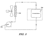
- the cooling water exiting the assembly then may be recirculated using a water pump 502, heat exchanger 504 and other devices and valves known in the art (not shown), thus creating a closed loop cooling system.
- the cooling water may dissipate the energy absorbed during the flow through the combustion camera assembly 100 before it is recirculated in the assembly by the water pump 502.
Landscapes
- Engineering & Computer Science (AREA)
- Multimedia (AREA)
- Signal Processing (AREA)
- Chemical & Material Sciences (AREA)
- Combustion & Propulsion (AREA)
- Mechanical Engineering (AREA)
- General Engineering & Computer Science (AREA)
- Studio Devices (AREA)
Abstract
Description
- The present invention generally relates to camera assemblies for viewing commercial combustion processes and, more particularly, but not by way of limitation, to combustion cameras that are liquid-cooled.
- Combustion cameras have been designed and used for the visualization of the combustion process in industrial gas turbines. The known design have utilized air to cool the camera used in the assembly, which generally is a charged-coupled device ("CCD") camera. Because of the limitations associated with using air as a coolant, these assemblies were relatively large. Nevertheless, these assemblies were still not sufficiently cooled, which often caused the CCD camera to malfunction because of its sensitivity to heat. The larger size required by the air cooling medium necessitated approximately a 2.0-inch (about 5 cm) diameter opening in the combustion chamber to view the combustion process. An opening of this size, however, is generally larger than what is acceptable in commercial gas turbines.
- Further, the known combustion cameras assemblies generally had been mounted on the outside of the gas turbine such that only a small portion of the camera, such as a lens set, extended into the high temperature and high pressure turbine environment. Mounting the combustion camera entirely inside the gas turbine, as now required by many commercial gas turbines, may greatly overheat the CCD camera and result in failure.
- Known combustion cameras generally included as a design feature a threaded mechanical fastener and gasket arrangement to mount and seal the quartz window cap, which is the transparent layer through which the CCD camera views the combustion process. This arrangement, however, has two undesirable effects: (1) a large camera housing diameter and (2) frequent servicing of the gaskets due to deterioration in the high temperature environment.
- Known combustion cameras also have included assemblies that have been adapted from camera designs used for viewing the combustion process in boilers. These adapted assemblies also were air-cooled and, as a result, were large in size. Another popular design included the separation of the lens from the camera. The lens of such camera assemblies generally included a "lens sets" that was used to project the combustion process image back to the CCD camera, which was located outside of the boiler. This arrangement allowed only the lens sets to be located in the extreme temperature and pressure conditions of the turbine. The drawbacks of this design include light attenuation and image distortion. Light attenuation prevents observation of low light aspects of the combustion process, such as observing the spark during the ignition process. Image distortion causes the image to be somewhat blurry, which prevents the observation of the fine details of the combustion process.
- Many of the newer industrial gas turbines require that combustion camera assemblies be designed to satisfy the following criteria: (1) operate while installed entirely within a 350 psi, 825 °F (24.6 kg/cm2, 440 °C) environment and while viewing a 3000 °F (1650 °C) combustion process; (2) cooled in such a manner that the cooling medium is not exhausted into the combustor, which can affect the combustion process thus making it not representative of the actual process; (3) view the combustion process through a 1.0-inch (about 2.5 cm) diameter opening; (4) limit the amount of light attenuation such that the CCD camera is able to view the operation of the spark plug during the combustion ignition process; (5) have an overall small size envelope that satisfies the space limitations of the commercial turbine and combustion test stand; and (6) be capable of many hours of operation without servicing due to the limited and difficult access to its location in the turbine or test stand. Accordingly, there is a long felt need for a combustion camera assembly that satisfies these requirements and improves upon the several limitations found in known designs that have been described above.
- According to a first aspect of the present invention, a liquid-cooled camera assembly that includes a camera for viewing the combustion process in an industrial gas turbine that further includes a tri-concentric tube assembly, and a window cap positioned at a first end of the tri-concentric tube assembly is described. The camera may be positioned adjacent to and behind the window cap and the tri-concentric tube assembly may form channels between the tubes that direct the flow of coolant to the camera from an inlet and from the camera to an outlet. The coolant may be water.
- In some embodiments, the width of the window cap may not exceed 1 inch (2.54 cm) in length. In other embodiments, the window cap may be cylindrical and may not exceed 1 inch (2.54 cm) in diameter. The window cap may be brazed quartz. The liquid-cooled combustion camera may further include a liquid circulation means for delivering a flow of liquid coolant to the inlet and draining the flow of liquid coolant from the outlet.
- In some embodiments, the liquid-cooled combustion camera further may include a housing that is connected to a second end of a tri-concentric tube assembly. The housing may include the inlet, which is connected to a supply hose, and the outlet, which is connected to a drain hose. The housing further may include a plurality of housing channels that direct the flow of water from the inlet to the tri-concentric tube assembly and from the tri-concentric tube assembly to the outlet.
- In other embodiments, the tri-concentric tube assembly may include an inner camera tube, an intermediate camera tube, and an outer camera tube. The inner camera tube may be positioned within the intermediate camera tube to create a first coolant channel and the intermediate camera tube may be positioned within the outer camera tube to create a second coolant channel. A first housing channel may direct the flow of coolant from the inlet to the first coolant channel and a second housing channel may direct the flow of coolant from the second coolant channel to the outlet.
- These and other features of the present invention will become apparent upon review of the following detailed description of the preferred embodiments when taken in conjunction with the drawings, in which:
- FIG. 1 is an exploded view illustrating an embodiment of a liquid-cooled combustion camera of the present invention.
- FIG. 2 is a plan view of the liquid-cooled combustion camera of FIG. 1.
- FIG. 3 is a side cross-sectional view of the liquid-cooled combustion camera of FIG. 1.
- FIG. 4 is a side cross-sectional view illustrating the flow of the liquid coolant through the liquid-cooled combustion camera of FIG. 1.
- FIG. 5 is a schematic of an example of a closed-loop cooling system that may be used with the liquid-cooled combustion camera of FIG. 1.
- Referring now to the drawings, in which like numerals refer to like elements throughout the several views, FIG. 1 demonstrates an embodiment of a liquid-cooled combustion camera assembly 100 as described herein. The liquid-cooled combustion camera 100 may include a
window cap 102. Thewindow cap 102 may be made of a brazed quartz material known in the art, such as GE-214. Thewindow cap 102 may be a transparent pressure boundary for acamera 103 to view the combustion process. Other known materials also may be used for thewindow cap 102 as long as they provide the necessary physical properties for operating in the combustion environment while allowing for a transparent window through which thecamera 103 may view the combustion process. - The diameter of the
window cap 102 may be approximately one inch (about 2.54 cm) or less. The thickness of thewindow cap 102 may be between 1/8 and 1/4 inches (about 3.18 and 6.35 cm). Thewindow cap 102 may be secured in awindow cap holder 104. - The liquid-cooled combustion camera assembly 100 further may include a tri-concentric tube configuration, which may include a
outer camera tube 106, aintermediate camera tube 108, and aninner camera tube 110. The tri-concentric tube configuration may be made of stainless steel, inconel, or other similar materials known in the art. These tubes may be sized such that theinner camera tube 110 fits within theintermediate camera tube 108 and theintermediate camera tube 108 fits within theouter camera tube 106. Further, when assembled, the sizing of the tri-concentric tube configuration may allow space to remain between the outer-radius of theinner camera tube 110 and the inner-radius of theintermediate camera tube 108 and between the outer-radius of theintermediate camera tube 108 and the inner-radius of theouter camera tube 106. This space may create channels through which fluid may pass. - The
window cap holder 104 may be fixed, by weld or other means known in the art, to one end of theouter camera tube 106, thus forming an integral part. The other end of theouter camera tube 106 may be attached and sealed to acamera mounting flange 112 via atube compression fitting 114. Thecamera mounting flange 112 may include acentral opening 116 into which the tube compression fitting 114 may mount. As described in more detail below and shown in more detail in Figs. 2 and 3, thecamera mounting flange 112 also may include interior channels that direct the flow of liquid through the interior thereof in a particular manner. Thecamera mounting flange 112 further may include a plurality ofopenings 118 through whichbolts 120 may be used to mount the liquid-cooled combustion camera 100 into a desired location. Thecamera mounting flange 112 may be made of stainless steel, inconel, or other similar materials known in the art. - The
intermediate camera tube 110 may be attached, by weld or other means, to anupper housing 122, thus forming an integral part. The upper housing may be made of stainless steel, inconel, or other similar materials known in the art. Theupper housing 122 may include aninlet 124 and anoutlet 126. Theinlet 124 may connect to an inlet fitting 128 so that theinlet 124 may be connected to a supply hose (not shown). A pump (not shown) may circulate pressurized liquid through the supply hose and into theinlet 124. The pump may be any pump known in the art, such as a centrifugal pump, reciprocating pump or other similar pumps and fluid moving devices. Theoutlet 124 may connect to an outlet fitting 130 such that theoutlet 126 may be connect to a drain hose (not shown). As shown in more detail in Figs. 2 and 3, theupper housing 122 further may include interior channels that may direct the flow of water through the interior thereof in a particular manner. - An inlet
interior channel 202 in theupper housing 122 may direct the flow of water to from theinlet 124 to the space between the outer-radius of theinner camera tube 110 and the inner-radius of theintermediate camera tube 108. Anoutlet channel 132 in theupper housing 122 may direct the flow of liquid coolant from a connectingchannel 204 that is formed within thecamera mounting flange 112 to theoutlet 126. The connectingchannel 204 may direct the flow of liquid coolant from the space between the outer-radius of theintermediate camera tube 108 and the inner-radius of theouter camera tube 106 to theoutlet channel 132. Theupper housing 114 may be sealed to thecamera mounting flange 112 by an o-ring 134. The connectingchannel 204 of thecamera mounting flange 112 may be sealed to theoutlet channel 132 of theupper housing 122 by an o-ring 136. By machining these cooling passages in thecamera mounting flange 112 and theupper housing 122, which together may be referred to as the housing of the assembly, the overall size of the device may be reduced, which is significant given the space constraints associated with the installation of observation and test devices in commercial combustion devices. - A
camera holder 138 may support and align thecamera 103, which may be a CCD camera, in proximity to thewindow cap 102 during use. TheCCD camera 103 may be selected from cameras of this type known in the art. A plurality ofscrews 139 may rigidly fix theCCD camera 103 in place in thecamera holder 138. Thecamera holder 110 may be welded or attached by other means known in the art to one end of theinner camera tube 110. Acamera cable 140 of the CCD camera then may be routed up theinner camera tube 110 and directed into the water supply hose, where it may exit the gas turbine to connect with camera imaging equipment (not shown) known in the art so that the images theCCD camera 103 views may be examined and recorded. This approach may position theCCD camera 103 in close proximity to the combustion flame with little or no light attenuation, which may produce a bright, clear, and sharp image of the combustion process while protecting the lowtemperature CCD camera 103 andcamera cable 140 from the high temperatures of the turbine environment. - At its other end, the
inner camera tube 110 may be fixed to a fourbolt flange 141. The fourbolt flange 141 may align with several openings (not shown) on the top surface of theupper housing 122 and be attached thereto by bolts 142, which, when assembled, may mechanically fix and align theinner camera tube 110 in theupper housing 114 and within theintermediate camera tube 108. - An
upper camera flange 144 and o-ring 146 may be positioned above the fourbolt flange 141 and used in conjunction with a plurality of sealingbolts 148 to seal and draw the assembly together. The sealingbolts 148 may feed throughopenings 150 in theupper camera flange 144 andopenings 152 in theupper housing 122 to insert into treaded openings (not shown) in the top surface of thecamera mounting flange 112. In drawing together the assembly, the sealingbolts 148 also may mechanically fix and align theintermediate camera tube 108 in theouter camera tube 106. Those of ordinary skill in the art will appreciate that other known means may be used to seal and draw the assembly together. - The design of the liquid-cooled combustion camera 100 may allow the device to be efficiently assembled and serviced. For example, if the
window cap 102 becomes damaged, it may be efficiently replaced by disconnecting theouter camera tube 106 from the tube compression fitting 114 and replacing thewindow cap 102/window cap holder 104/outer camera tube 106 assembly with a new one. - Further, the use of a brazed
quartz window cap 102 may allow the diameter of the camera housing, i.e., which generally comprises the diameter of thewindow cap 102 and thewindow cap holder 104 or similar components, to be reduced to a 1-inch (about 2.54 cm) or less diameter by eliminating threaded mechanical attachments. Brazing the quartz to the metal holder may fuse the quartz and metal together, thus forming a hermatic seal. As such, mechanical fasteners may not be required to restrain/fix the quartz to the metal, which may allow for the reduction in size of the assembly. The brazed quartz approach also may eliminate the need for high temperature gaskets or seals that typically require frequent servicing in high temperature and pressure environments. That is, the seal formed by the brazed quartz approach may eliminate the need for gaskets or other seals. - Also, the
camera holder 138/inner camera tube 110/fourbolt flange 141 assembly may allow for efficient installation and replacement of theCCD camera 103. TheCCD camera 103 may be installed by inserting it down theinner camera tube 110 into thecamera holder 138 and tightening the threescrews 139 while theinner camera tube 110 is removed from theupper housing 122. Theinner support tube 110 then may be inserted into theupper housing 122 and fixed into place with theseal bolts 148. - In use, the liquid-cooled combustion camera assembly 100 may protect and cool a
CCD camera 103 that is inside the high pressure and high temperature environment of an industrial gas turbine with an internal flow of liquid coolant. - The greater cooling capacity of water over air may allow the size of the camera housing to be reduced. For this example of use, the liquid coolant will be described as water, though other liquids may be used.
- As shown in FIG. 3, cooling water may enter the
upper housing 122 throughinlet 124 from outside the turbine via a flexible metal hose (not shown) that attaches to the inlet fitting 128. A water pump (not shown) may supply a flow of pressurized water through the flexible metal hose. The water may be supplied at a pressure of between 10 to 80 psi and at a flow rate of about 5 to 30 gal/s (approximately 0.32 to 1.89 I/s). The cooling water then may flow through the inletinterior channel 202 to the space defined by the outer radius of the inner camera table 110 and the inner radius of theintermediate camera tube 108. The water then may flow down this space toward thewindow cap 102. When the cooling water reaches thewindow cap 102, thewindow cap 102 may redirect the flow 180 degrees such that the cooling water is directed to the space defined by the outer radius of theintermediate camera tube 108 and the inner radius of theouter camera tube 106. The cooling water may then flow through this space back toward thecamera mounting flange 112. At thecamera mounting flange 112, the cooling water may be directed into the connectingchannel 204 machined in thecamera mounting flange 112. - From the connecting
channel 204, the cooling water may be directed into theoutlet channel 132 in theupper housing 122. The cooling water may then flow through theoutlet channel 132 to theoutlet 126 and the outlet fitting 130, where it may be carried away by a flexible metal hose (not shown) that is connected to the outlet fitting 130. In this manner, thecamera 103 may be cooled without discharging any coolant into the combustion chamber that might affect the combustion process. The coolant may enter the assembly at about 80 °F (approximately 26.7 °C) and exit it at about 92 °F (approximately 33.3 °C). Being cooled in this manner, the liquid-cooled combustion camera 100 may operate within an industrial gas turbine, where often pressures exceed 350 psi and temperatures exceed 900 °F (approximately 482.2 °C). - As shown in Fig. 5, the cooling water exiting the assembly then may be recirculated using a
water pump 502,heat exchanger 504 and other devices and valves known in the art (not shown), thus creating a closed loop cooling system. In theheat exchanger 504, the cooling water may dissipate the energy absorbed during the flow through the combustion camera assembly 100 before it is recirculated in the assembly by thewater pump 502. Those of ordinary skill in the art will appreciate other methods of satisfying this heat transfer objective. - It should be apparent that the foregoing relates only to the preferred embodiments of the present invention and that numerous changes and modifications may be made herein without departing from the spirit and scope of the invention as defined by the following claims and the equivalents thereof.
-
- 100
- Liquid-cooled combustion camera
- 102
- window cap
- 103
- camera
- 104
- window camp holder
- 106
- outer camera tube
- 108
- intermediate camera tube
- 110
- inner camera tube
- 112
- camera mounting flange
- 114
- tube compression fitting
- 116
- central opening
- 118
- openings
- 120
- bolts
- 122
- upper housing
- 124
- inlet
- 126
- outlet
- 128
- inlet fitting
- 130
- outlet fitting
- 132
- outlet channel
- 134
- o-ring
- 136
- o-ring
- 138
- camera holder
- 139
- screws
- 140
- camera cable
- 141
- four bolt flange
- 142
- bolts
- 144
- upper camera flange
- 146
- o-ring
- 148
- sealing bolts
- 150
- openings
- 152
- openings
- 202
- inlet interior channel
- 204
- connecting channel
- 502
- water pump
- 504
- heat exchanger
Claims (10)
- A liquid-cooled camera assembly (100) that includes a camera (103) for viewing the combustion process in an industrial gas turbine, comprising:a tri-concentric tube assembly (106, 108, 110); anda window cap (102) positioned at a first end of the tri-concentric tube assembly (106, 108, 110);wherein the camera (103) is positioned adjacent to and behind the window cap (102) and the tri-concentric tube assembly (106, 108, 110) forms channels between the tubes that direct the flow of coolant to the camera (103) from an inlet (124) and from the camera (103) to an outlet (126).
- The liquid-cooled combustion camera (100) of claim 1, wherein the coolant is water.
- The liquid-cooled combustion camera (100) of claim 1 or claim 2, wherein the width of the window cap (102) does not exceed 1 inch (2.54 cm).
- The liquid-cooled combustion camera (100) of any preceding claim wherein the window cap (102) is cylindrical and does not exceed 1 inch (2.54 cm) in diameter.
- The liquid-cooled combustion camera (100) of any preceding claim, wherein the window cap (102) comprises brazed quartz.
- The liquid-cooled combustion camera (100) of any preceding claim, further comprising liquid circulation means (502) for delivering a flow of liquid coolant to the inlet (124) and draining the flow of liquid coolant from the outlet (126).
- The liquid-cooled combustion camera (100) of any preceding claim, further comprising a housing (112, 122) connected to a second end of a tri-concentric tube assembly (106, 108, 110);
wherein the housing (112, 122) includes the inlet (124), which is connected to a supply hose, and the outlet (126), which is connected to a drain hose. - The liquid-cooled combustion camera (100) of claim 7, wherein the housing (112, 122) includes a plurality of housing channels that direct the flow of water from the inlet (124) to the tri-concentric tube assembly (106, 108, 110) and from the tri-concentric tube assembly (106, 108, 110) to the outlet (126).
- The liquid-cooled combustion camera (100) of claim 8, wherein the tri-concentric tube assembly (106, 108, 110) comprises an inner camera (110) tube, an intermediate camera tube (108), and an outer camera tube (106); and
wherein the inner camera tube is positioned within the intermediate camera tube (108) to create a first coolant channel and the intermediate camera tube (108) is positioned within the outer camera tube (106) to create a second coolant channel. - The liquid-cooled combustion camera (100) of claim 9, wherein a first housing channel (202) directs the flow of coolant from the inlet (124) to the first coolant channel and a second housing channel (132) directs the flow of coolant from the second coolant channel to the outlet (126).
Applications Claiming Priority (1)
| Application Number | Priority Date | Filing Date | Title |
|---|---|---|---|
| US11/162,702 US7336897B2 (en) | 2005-09-20 | 2005-09-20 | Liquid-cooled combustion camera |
Publications (1)
| Publication Number | Publication Date |
|---|---|
| EP1765003A1 true EP1765003A1 (en) | 2007-03-21 |
Family
ID=37521870
Family Applications (1)
| Application Number | Title | Priority Date | Filing Date |
|---|---|---|---|
| EP06254788A Withdrawn EP1765003A1 (en) | 2005-09-20 | 2006-09-14 | Liquid cooled combustion monitoring camera |
Country Status (4)
| Country | Link |
|---|---|
| US (1) | US7336897B2 (en) |
| EP (1) | EP1765003A1 (en) |
| JP (1) | JP2007085345A (en) |
| CN (1) | CN1945124B (en) |
Cited By (4)
| Publication number | Priority date | Publication date | Assignee | Title |
|---|---|---|---|---|
| US8461474B2 (en) | 2010-03-31 | 2013-06-11 | Sciaky, Inc. | Raster methodology, apparatus and system for electron beam layer manufacturing using closed loop control |
| US8546717B2 (en) | 2009-09-17 | 2013-10-01 | Sciaky, Inc. | Electron beam layer manufacturing |
| US8598523B2 (en) | 2009-11-13 | 2013-12-03 | Sciaky, Inc. | Electron beam layer manufacturing using scanning electron monitored closed loop control |
| EP3747558B1 (en) * | 2019-06-07 | 2023-09-06 | MML Solutions GmbH | Device, machine or machine component with the device, method for monitoring by means of the device and method for cleaning the device |
Families Citing this family (9)
| Publication number | Priority date | Publication date | Assignee | Title |
|---|---|---|---|---|
| US8432440B2 (en) * | 2009-02-27 | 2013-04-30 | General Electric Company | System and method for adjusting engine parameters based on flame visualization |
| WO2011079422A1 (en) * | 2009-12-30 | 2011-07-07 | 北京航天万源煤化工工程技术有限公司 | Flame detecting device |
| KR101187822B1 (en) | 2010-06-30 | 2012-10-05 | 한국전력공사 | Burner Monitoring System |
| US8387399B1 (en) | 2011-09-12 | 2013-03-05 | General Electric Company | System and method for controlling a combustor assembly |
| US10197473B2 (en) * | 2015-12-09 | 2019-02-05 | General Electric Company | System and method for performing a visual inspection of a gas turbine engine |
| CN105628384B (en) * | 2015-12-21 | 2018-02-27 | 中国燃气涡轮研究院 | A kind of aeroengine thrust augmentation combustion monitoring device |
| WO2022072943A1 (en) * | 2020-10-02 | 2022-04-07 | Delta Controls Corporation | Reactor camera |
| US11995925B2 (en) * | 2020-12-10 | 2024-05-28 | Ford Global Technologies, Llc | Vision system for a vehicle coolant system |
| DE102021200378B4 (en) | 2021-01-15 | 2025-03-20 | Carl Zeiss Industrielle Messtechnik Gmbh | Image capture device and method for manufacturing an image capture device |
Citations (3)
| Publication number | Priority date | Publication date | Assignee | Title |
|---|---|---|---|---|
| US3277238A (en) * | 1964-01-24 | 1966-10-04 | Diamond Power Speciality | Cooling system utilizing a ranque tube |
| WO2001051854A1 (en) * | 2000-01-14 | 2001-07-19 | Ecomb Ab | A feeding device for a fluid to a combustion chamber |
| GB2390675A (en) * | 2002-07-10 | 2004-01-14 | Univ Greenwich | Flame characteristic monitor using digitising image camera |
Family Cites Families (10)
| Publication number | Priority date | Publication date | Assignee | Title |
|---|---|---|---|---|
| JPS60232488A (en) * | 1984-05-01 | 1985-11-19 | 品川白煉瓦株式会社 | Device for observing inside of furnace |
| US4749337A (en) * | 1987-08-20 | 1988-06-07 | American Sigma, Inc. | Reciprocating bladder pump, and methods of constructing and utilizing same |
| US4978608A (en) * | 1987-09-04 | 1990-12-18 | Molecular Devices Corporation | DNA detection system |
| JPH02157515A (en) * | 1988-12-09 | 1990-06-18 | Hitachi Ltd | Gas turbine combustor flame spectroscopic imaging device |
| JPH03267617A (en) * | 1990-03-19 | 1991-11-28 | Hitachi Ltd | Flame monitoring device in gas turbine combustor |
| CN2166322Y (en) * | 1993-04-30 | 1994-05-25 | 李传统 | Imaging lens cooling device for flame supervising device |
| CN2226204Y (en) * | 1995-09-01 | 1996-05-01 | 电子工业部第五十四研究所 | Boiler flame television apparatus |
| US6778209B1 (en) * | 1997-09-26 | 2004-08-17 | Diamond Power International, Inc. | Furnace video camera apparatus |
| GB2385735B (en) * | 2002-02-21 | 2003-12-31 | Keymed | Image capture and display system |
| US20060088793A1 (en) * | 2004-10-22 | 2006-04-27 | Siemens Westinghouse Power Corporation | Optical viewing system for monitoring a wide angle area of interest exposed to high temperature |
-
2005
- 2005-09-20 US US11/162,702 patent/US7336897B2/en not_active Expired - Fee Related
-
2006
- 2006-09-14 EP EP06254788A patent/EP1765003A1/en not_active Withdrawn
- 2006-09-19 JP JP2006252366A patent/JP2007085345A/en active Pending
- 2006-09-19 CN CN2006101395916A patent/CN1945124B/en not_active Expired - Fee Related
Patent Citations (3)
| Publication number | Priority date | Publication date | Assignee | Title |
|---|---|---|---|---|
| US3277238A (en) * | 1964-01-24 | 1966-10-04 | Diamond Power Speciality | Cooling system utilizing a ranque tube |
| WO2001051854A1 (en) * | 2000-01-14 | 2001-07-19 | Ecomb Ab | A feeding device for a fluid to a combustion chamber |
| GB2390675A (en) * | 2002-07-10 | 2004-01-14 | Univ Greenwich | Flame characteristic monitor using digitising image camera |
Cited By (12)
| Publication number | Priority date | Publication date | Assignee | Title |
|---|---|---|---|---|
| US8546717B2 (en) | 2009-09-17 | 2013-10-01 | Sciaky, Inc. | Electron beam layer manufacturing |
| US9399264B2 (en) | 2009-09-17 | 2016-07-26 | Sciaky, Inc. | Electron beam layer manufacturing |
| US10189114B2 (en) | 2009-09-17 | 2019-01-29 | Sciaky, Inc. | Electron beam layer manufacturing |
| US11344967B2 (en) | 2009-09-17 | 2022-05-31 | Sciaky, Inc. | Electron beam layer manufacturing |
| US12210327B2 (en) | 2009-09-17 | 2025-01-28 | Sciaky, Inc. | Electron beam layer manufacturing |
| US8598523B2 (en) | 2009-11-13 | 2013-12-03 | Sciaky, Inc. | Electron beam layer manufacturing using scanning electron monitored closed loop control |
| US8809780B2 (en) | 2009-11-13 | 2014-08-19 | Sciaky, Inc. | Electron beam layer manufacturing using scanning electron monitored closed loop control |
| US8461474B2 (en) | 2010-03-31 | 2013-06-11 | Sciaky, Inc. | Raster methodology, apparatus and system for electron beam layer manufacturing using closed loop control |
| US9174300B2 (en) | 2010-03-31 | 2015-11-03 | Sciaky, Inc. | Raster methodology, apparatus and system for electron beam layer manufacturing using closed loop control |
| US10071437B2 (en) | 2010-03-31 | 2018-09-11 | Sciaky, Inc. | Raster methodology, apparatus and system for electron beam layer manufacturing using closed loop control |
| US10946474B2 (en) | 2010-03-31 | 2021-03-16 | Sciaky, Inc. | Raster methodology, apparatus and system for electron beam layer manufacturing using closed loop control |
| EP3747558B1 (en) * | 2019-06-07 | 2023-09-06 | MML Solutions GmbH | Device, machine or machine component with the device, method for monitoring by means of the device and method for cleaning the device |
Also Published As
| Publication number | Publication date |
|---|---|
| JP2007085345A (en) | 2007-04-05 |
| CN1945124B (en) | 2011-08-03 |
| US20070065141A1 (en) | 2007-03-22 |
| CN1945124A (en) | 2007-04-11 |
| US7336897B2 (en) | 2008-02-26 |
Similar Documents
| Publication | Publication Date | Title |
|---|---|---|
| US7336897B2 (en) | Liquid-cooled combustion camera | |
| US7278516B2 (en) | Apparatus and method for bearing lubrication in turbine engines | |
| US20080053060A1 (en) | Bypass lip seal | |
| EP1898069B1 (en) | Turbofan bypass duct air cooled fluid cooler installation | |
| EP1040665B1 (en) | Furnace video camera apparatus | |
| US4872689A (en) | Mechanical seal with heat exchanger | |
| US11698004B2 (en) | Aircraft propulsion assembly comprising air-liquid heat exchangers | |
| EP3828399B1 (en) | Internal fuel/air heat exchangers | |
| CN109116547A (en) | Endoscope | |
| JP5259463B2 (en) | High temperature dead end seal | |
| US6778209B1 (en) | Furnace video camera apparatus | |
| US20040226694A1 (en) | Heat exchanger with removable core | |
| CN109790750A (en) | Screw compressor for commercial vehicle | |
| US20140176695A1 (en) | Imaging system for inspecting a turbine | |
| CN218450312U (en) | High-temperature protection device for camera | |
| US20220349662A1 (en) | Connector | |
| EP1249591A2 (en) | Cooling structure for gas turbines | |
| JP7034603B2 (en) | Industrial oil degassing system and method | |
| CN219656629U (en) | Sintering machine tail thermal imaging device | |
| KR101187822B1 (en) | Burner Monitoring System | |
| CN208818931U (en) | Endoscope | |
| CN220453698U (en) | Flue gas cooling device for power station boiler | |
| CN113507556B (en) | Endoscope assembly for a gas turbine | |
| CN105423799B (en) | Remanufacture the method for the shell of heat exchanger and the shell remanufactured | |
| CA2358374C (en) | Furnace video camera apparatus |
Legal Events
| Date | Code | Title | Description |
|---|---|---|---|
| PUAI | Public reference made under article 153(3) epc to a published international application that has entered the european phase |
Free format text: ORIGINAL CODE: 0009012 |
|
| AK | Designated contracting states |
Kind code of ref document: A1 Designated state(s): AT BE BG CH CY CZ DE DK EE ES FI FR GB GR HU IE IS IT LI LT LU LV MC NL PL PT RO SE SI SK TR |
|
| AX | Request for extension of the european patent |
Extension state: AL BA HR MK YU |
|
| 17P | Request for examination filed |
Effective date: 20070921 |
|
| 17Q | First examination report despatched |
Effective date: 20071026 |
|
| AKX | Designation fees paid |
Designated state(s): CH DE FR GB LI |
|
| STAA | Information on the status of an ep patent application or granted ep patent |
Free format text: STATUS: THE APPLICATION IS DEEMED TO BE WITHDRAWN |
|
| 18D | Application deemed to be withdrawn |
Effective date: 20110817 |