EP1764954A1 - Information processing apparatus and control method for the information processing apparatus - Google Patents
Information processing apparatus and control method for the information processing apparatus Download PDFInfo
- Publication number
- EP1764954A1 EP1764954A1 EP06120327A EP06120327A EP1764954A1 EP 1764954 A1 EP1764954 A1 EP 1764954A1 EP 06120327 A EP06120327 A EP 06120327A EP 06120327 A EP06120327 A EP 06120327A EP 1764954 A1 EP1764954 A1 EP 1764954A1
- Authority
- EP
- European Patent Office
- Prior art keywords
- aparatus
- processing aparatus
- information processing
- service area
- radio
- Prior art date
- Legal status (The legal status is an assumption and is not a legal conclusion. Google has not performed a legal analysis and makes no representation as to the accuracy of the status listed.)
- Granted
Links
Images


Classifications
-
- H—ELECTRICITY
- H04—ELECTRIC COMMUNICATION TECHNIQUE
- H04W—WIRELESS COMMUNICATION NETWORKS
- H04W4/00—Services specially adapted for wireless communication networks; Facilities therefor
- H04W4/02—Services making use of location information
- H04W4/029—Location-based management or tracking services
-
- G—PHYSICS
- G06—COMPUTING OR CALCULATING; COUNTING
- G06F—ELECTRIC DIGITAL DATA PROCESSING
- G06F21/00—Security arrangements for protecting computers, components thereof, programs or data against unauthorised activity
- G06F21/70—Protecting specific internal or peripheral components, in which the protection of a component leads to protection of the entire computer
- G06F21/88—Detecting or preventing theft or loss
-
- H—ELECTRICITY
- H04—ELECTRIC COMMUNICATION TECHNIQUE
- H04W—WIRELESS COMMUNICATION NETWORKS
- H04W4/00—Services specially adapted for wireless communication networks; Facilities therefor
- H04W4/02—Services making use of location information
-
- H—ELECTRICITY
- H04—ELECTRIC COMMUNICATION TECHNIQUE
- H04W—WIRELESS COMMUNICATION NETWORKS
- H04W48/00—Access restriction; Network selection; Access point selection
- H04W48/02—Access restriction performed under specific conditions
- H04W48/04—Access restriction performed under specific conditions based on user or terminal location or mobility data, e.g. moving direction, speed
-
- G—PHYSICS
- G06—COMPUTING OR CALCULATING; COUNTING
- G06F—ELECTRIC DIGITAL DATA PROCESSING
- G06F2221/00—Indexing scheme relating to security arrangements for protecting computers, components thereof, programs or data against unauthorised activity
- G06F2221/21—Indexing scheme relating to G06F21/00 and subgroups addressing additional information or applications relating to security arrangements for protecting computers, components thereof, programs or data against unauthorised activity
- G06F2221/2111—Location-sensitive, e.g. geographical location, GPS
-
- H—ELECTRICITY
- H04—ELECTRIC COMMUNICATION TECHNIQUE
- H04W—WIRELESS COMMUNICATION NETWORKS
- H04W24/00—Supervisory, monitoring or testing arrangements
-
- H—ELECTRICITY
- H04—ELECTRIC COMMUNICATION TECHNIQUE
- H04W—WIRELESS COMMUNICATION NETWORKS
- H04W64/00—Locating users or terminals or network equipment for network management purposes, e.g. mobility management
Definitions
- One embodiment of the invention relates to a security technique which is appropriate to apply, for instance, to a notebook-sized personal computer easy to carry.
- each notebook-sized personal computer has been extremely enhanced its performance. And, for instance, it is easy to house the notebook-sized personal computer in a drawer of a desk and a locker, so that the number of users adopting the notebook-sized personal as tools for the deskwork has increased.
- the present invention is invented by given consideration to such situation, and its object is to provide an information processing apparatus and a control method for the information processing apparatus which realizes to restrict use at an outside of a predetermined area.
- an information processing apparatus including a function of performing dial-up access to a server computer through a radio base station forming a radio service area in a predetermined geographic area, includes a monitoring unit configured to monitor whether or not the processing apparatusus is placed in a radio service area to which the processing apparatusus belongs when dial-up access is performed successfully, and an automatic log-off unit configured to forcibly complete use of the processing apparatusus when the monitoring unit detects that the processing apparatusus depart from the service area.
- the information processing apparatus and the control method for the information processing apparatus which realizes to restrict the use at the outside of the predetermined area can be provided.
- FIG. 1 shows the operation environment of the information processing apparatus regarding the one embodiment of the present invention.
- an information processing apparatus 6 is a notebook-sized personal computer which is provided for each staff of an enterprise.
- which base station 4 makes the personal computer be operable only under the control by the defined base station 4 and the information about the defined base station 4 is registered in a server computer 1 together with user identification information.
- Each base station 4 forms radio service areas 5, respectively, to make radio communication with mobile stations.
- the processing apparatus 6 has a function to execute a radio communication with the base station 4, as a mobile station.
- a control station 3 houses each base station 4 to relay to a public line network 2.
- the server computer 1 is connected to the line network 2.
- the information processing apparatus 6 can use dial-up access to the server computer 1 in logging on.
- the request for the dial-up access is transmitted to the server computer 1 via the base station 4.
- the server computer 1 checks a user name and a password, and in addition to this, further checks whether or not the base station 4 which has relayed the transmission of the request coincides with a base station 4 defined to enable operating the processing apparatus 6. If all of the user names, passwords and base stations 4 are coincident with one another, the server computer 1 then replies an authentication establishment of the dial-up access.
- the processing apparatus 6 which has received the reply of the authentication establishment carries on with monitoring whether or not the processing apparatus 6 itself is placed within the radio service area 5 to which it belongs after completing the dial-up access to the server computer 1 after logging on.
- the monitoring does not need to perform an actual data transmission/reception to/from the base station 4 forming the service area 5. And it may determine that the processing apparatus 6 departs from the service area 5 when an electric field intensity of a radio signal from the base station 4 reaches a level not more than a prescribed level, or that it departs form the service area 5 when handoff occurs.
- the processing apparatus 6 logs off voluntarily and forcibly.
- the processing apparatus 6 becomes possible to operate only under the predetermined base station 4, and in other words, the use at the outside of the service area 5 formed by the prescribed base station 4 is subjected to be restricted.
- FIG. 2 is a perspective view when viewed from the front side of the computer 6 in a state where its display unit is opened.
- the computer 6 consists of a computer main body 11 and a display unit 12.
- the display unit 12 has a built-in display device consisting of a liquid crystal display (LCD) 20, and the display screen of the LCD 20 is positioned at the almost the center of the display unit 12.
- LCD liquid crystal display
- the display unit 12 is supported by the computer main body 11 and attached rotatably between an opening position at which the upper surface of the main body 11 is exposed and a closing position at which the upper surface thereof is covered.
- the main body 11 has a thin box-shaped housing, and a keyboard 13, a power button 14 to turn on/off the main body 6 and a touch pad 15 are disposed on the upper surface of the housing.
- the main body 11 has a communication device built-in.
- a wireless communication switch 16 is disposed on the left side surface of the main body 11.
- the communication switch 16 is an operation switch to permit or inhibit an execution of a radio communication.
- the communication switch 16 is set to one state of a first state allowing executing the radio communication and a second state inhibiting executing the radio communication. With setting the communication switch 16 to the second state, it becomes possible to prevent the radio communication from being executed at a place, for instance, such as a hospital where the use of electric waves is restricted.
- FIG. 3 is a perspective view showing the exterior appearance of the computer 6 in the state in which the display unit 12 is closed.
- a sub-display 21 is arranged on the rear surface of the display unit 12.
- the sub-display 21 displays information, etc. indicating, for example, the electric field intensity of the radio signal from a base station. Owing to the sub-display unit 21, a user can confirm whether or not the current position of the computer 6 is within the communication service area even in the state in which the display unit 12 is closed.
- FIG. 4 shows an example of the hardware configuration of the computer 6.
- the computer 6 includes a CPU 111, a north bridge 112, a main memory 113, a graphics controller 114, a south bridge 115, a hard disk drive (HDD) 116, a flash basic input output system (BIOS)-ROM 118, embedded controller/keyboard controller (EC/KBC) IC 119, a power supply circuit 120, an auxiliary processor unit (APU) 130, communication devices 131-134, etc.
- a CPU 111 central processing unit
- APU auxiliary processor unit
- APU auxiliary processor unit
- the CPU 111 is a main processor to control operations of the computer 6.
- the CPU 111 executes an operating system (OS) and a variety of application programs/utility programs which are loaded into the main memory 113 from the HDD 116.
- the CPU 111 also executes a BIOS stored in the flash BIOS-ROM 118.
- the BIOS is a program to control hardware.
- the north bridge 112 is a bridge device to connect between a local bus of the CPU 111 and the south bridge 115.
- the north bridge 112 also has a function of executing communication with the graphics controller 114 via an accelerated graphics port (AGP) bus, etc.
- the north bridge 112 further has a main controller to control the main memory 113 built-in.
- the graphics controller 114 is a display controller to control the LCD 20 used as a display monitor of the computer 6.
- the south bridge 115 is connected to a peripheral component interconnect (PCI) bus and to a low pin count (LPC) bus independently.
- PCI peripheral component interconnect
- LPC low pin count
- the south bridge 115 also incorporates an IDE controller to control the HDD 116.
- the EC/KBC 119 is a one-chip microcomputer in which an embedded controller to manage a power source and a keyboard controller to control the keyboard (KB) 13 and the touch pad 15, etc.
- the EC/KBC 119 cooperates with the power supply circuit 120 to turn on/off the computer 6 depending on the operations of the power button switch 14 by the user.
- the power supply circuit 120 uses an external power source to be supplied through a battery 121 or an AC adopter 122 to generate operation power to be supplied to each component of the computer 6. Even in a state in which the computer 6 is turned off, the power supply circuit 120 supplies the operation power to the EC/KBC 119.
- the EC/KBC 119 also detects the on/off of the communication switch 16 to transfer the fact to the BIOS.
- the APU 130 has a function to monitor each operation of the communication devices 131-134. That is, the APU 130 is electrically connected to each communication devices 131-134 through serial buses (for example, SMBUS, USB, etc.) in a point-to-point manner and capable of communicating with each communication device 131-134 directly.
- the APU 130 determines whether or not each of the communication devices 131-134 is available, namely, whether or not each of the communication devices 131-134 is in an executable state of a communication with an external device via a wired or radio network by making communications with each communication device 131-134.
- the APU 130 also has a function of controlling the sub-display 21.
- the communication device 131 is a radio communication device and executes radio communication with base station 4 in accordance with a radio communication specification such as a 3G Wireless LAN.
- the 3G wireless LAN is a wide radio network of a mobile phone network, etc.
- the communication device 132 is also a radio communication device and performs radio communication with an access point (AP) in accordance with the radio communication specification such as the Wireless LAN.
- AP access point
- the communication devices 133 and 134 are wired communication devices each.
- the communication device 133 performs communication with the external device via a Wired LAN.
- the communication device 134 is composed, for instance, of a modem to conduct communication with the external device via a telephone network.
- An OS 301 is a basic program integrally control a resource management of the computer 6 and has a variety of modules including a dial-up service 301a to execute dial-up access to the server computer 1 and a communication driver 301b to drive and control each radio communication device.
- the OS 301 When the computer 6 logs on, the OS 301 outputs an input screen for log-on shown in FIG. 6.
- the user inputs the user name and password in the input screen, and checks a check box (a2) of "log on by using a dial-up access” as well as specifies the server computer 1 for authentication in a field (a1) of "log-on destination".
- the computer 6 tries to make dial-up access to the server computer 1 through the dial-up service 301a of the OS 301. Then, when the server computer 1 confirms the user name, password and relay base station 4 to reply the authentication establishment of the dial-up access, log-on is permitted and the permission is notified to a support service 303 that is a utility program.
- the support service 303 is a resident-type program, and when the log-on is notified from the OS 301, it monitors whether or not the computer 6 has departed from the service area of the base station 4 to which the computer 6 has belonged at the time of the log-on as well as whether or not the handoff has occurred.
- the support service 303 monitors whether the communication switch 16 has not been switched to off through the BIOS 302 (which is stored in the flash BIOS-ROM 118).
- the support service 303 If the support service 303 detects that the computer 6 has departed from the service area 5 of the base station 4 to which the computer 6 has belonged in a log-on time or that the communication switch 16 has switched to off, the support service 303 transmits a log-off request to the OS 301 as measurements to the case in which, for instance, the computer 6 has carried away by the outsider. Thereby, the limitation of the use at the outside of the predetermined area is achieved.
- the computer 6 Even when an authorized user has erroneously carried away the computer 6 at the outside of the service area, the computer 6 is forcibly logged off. In this case, the user may return back to the predetermined area and log on again. In the case of having a suspend/resume function, the computer 6 becoming to be suspended in a log-on state, for such a situation, the computer 6 may log-off immediately in a suspension time and may log-off at timing when it is detected that the computer 6 has moved to the outside of the service area or it has switched off after a resume.
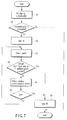
- FIG. 7 is a flowchart showing an operation procedure to restrict the use of the computer 6 at the outside of the prescribed area.
- the computer 6 firstly tries the dial-up access to the server computer for authentication 1 (block A1). If the authorized user (who can input a correct user name and password) is present in the predetermined area, the authentication is completed successfully (yes in block A2), so that the computer 6 is permitted to log on (block A3).
- the computer 6 When logged on, the computer 6 checks by itself whether the self has departed from the service area of the base station 4 in logging on (block A4,A5) and also checks whether or not the wireless communication switch 16 has switched off (block A6,A7).
- the computer 6 in the embodiment is controlled so as to become operable only within the predetermined area of the base station 4. That is to say, it is achieved that the computer 6 is restricted to be used at the outside of the predetermined area.
Landscapes
- Engineering & Computer Science (AREA)
- Signal Processing (AREA)
- Computer Networks & Wireless Communication (AREA)
- Theoretical Computer Science (AREA)
- Computer Hardware Design (AREA)
- Computer Security & Cryptography (AREA)
- Software Systems (AREA)
- Physics & Mathematics (AREA)
- General Engineering & Computer Science (AREA)
- General Physics & Mathematics (AREA)
- Mobile Radio Communication Systems (AREA)
- Small-Scale Networks (AREA)
- Telephonic Communication Services (AREA)
- Information Transfer Between Computers (AREA)
- Transceivers (AREA)
Abstract
Description
- One embodiment of the invention relates to a security technique which is appropriate to apply, for instance, to a notebook-sized personal computer easy to carry.
- In recent years, deskwork in an office has been performed by using a personal computer generally.
- Recently, many offices have laid wireless LANs therein; connected personal computers to the wireless LANs without using any cable at their own conveniences and each staff of the office has become possible to simply take in necessary data from a shared file server, etc.
- In the personal computers, there are a variety of types such as a desktop-type and a notebook-sized, so each notebook-sized personal computer has been extremely enhanced its performance. And, for instance, it is easy to house the notebook-sized personal computer in a drawer of a desk and a locker, so that the number of users adopting the notebook-sized personal as tools for the deskwork has increased.
- Meanwhile, as for the notebook-sized personal computer, running a large risk of a theft such that it is carried away by an outsider is unavoidable.
Nowadays in which the capacity of storage as well as the performance of the notebook-size personal computer have been enhanced, storing a large volume of important data has lost much of its novelty now. Therefore, it is needed to take account of sufficient measures for the case that the notebook-sized personal computer has been carried away by the outsider. - The present invention is invented by given consideration to such situation, and its object is to provide an information processing aparatus and a control method for the information processing aparatus which realizes to restrict use at an outside of a predetermined area.
- To achieve the forgoing object, an information processing aparatus including a function of performing dial-up access to a server computer through a radio base station forming a radio service area in a predetermined geographic area, includes a monitoring unit configured to monitor whether or not the processing aparatus is placed in a radio service area to which the processing aparatus belongs when dial-up access is performed successfully, and an automatic log-off unit configured to forcibly complete use of the processing aparatus when the monitoring unit detects that the processing aparatus depart from the service area.
- According to the present invention, the information processing aparatus and the control method for the information processing aparatus which realizes to restrict the use at the outside of the predetermined area can be provided.
- The invention can be more fully understood from the following detailed description when taken in conjunction with the accompanying drawings, in which:
- FIG. 1 is an exemplary view showing an operation environment of an information processing aparatus regarding an embodiment of the present invention;
- FIG. 2 is an exemplary perspective view showing an exterior appearance of the full face of the information processing aparatus of the embodiment;
- FIG. 3 is an exemplary perspective view showing an exterior appearance in a state in which a display unit of the information processing aparatus of the embodiment is closed;
- FIG. 4 is an exemplary block diagram showing a configuration of hardware of the information processing aparatus of the embodiment;
- FIG. 5 is an exemplary block diagram showing a configuration of software of the information processing aparatus of the embodiment;
- FIG. 6 is an exemplary view exemplifying an input screen for logging on displayed on the information processing aparatus of the embodiment; and
- FIG. 7 is an exemplary flowchart showing an operation procedure for restricting use at the outside of a predetermined area by the embodiment.
- Various embodiments according to the invention will be described hereinafter with reference to the accompanying drawings.
- FIG. 1 shows the operation environment of the information processing aparatus regarding the one embodiment of the present invention. Here, it is presumed, for instance, that an
information processing aparatus 6 is a notebook-sized personal computer which is provided for each staff of an enterprise. To provide the personal computer to each staff, it is defined that whichbase station 4 makes the personal computer be operable only under the control by thedefined base station 4 and the information about thedefined base station 4 is registered in aserver computer 1 together with user identification information. - Each
base station 4 forms radio service areas 5, respectively, to make radio communication with mobile stations. Theprocessing aparatus 6 has a function to execute a radio communication with thebase station 4, as a mobile station. Acontrol station 3 houses eachbase station 4 to relay to apublic line network 2. Theserver computer 1 is connected to theline network 2. - The
information processing aparatus 6 can use dial-up access to theserver computer 1 in logging on. The request for the dial-up access is transmitted to theserver computer 1 via thebase station 4. Upon receiving the request, theserver computer 1 checks a user name and a password, and in addition to this, further checks whether or not thebase station 4 which has relayed the transmission of the request coincides with abase station 4 defined to enable operating theprocessing aparatus 6. If all of the user names, passwords andbase stations 4 are coincident with one another, theserver computer 1 then replies an authentication establishment of the dial-up access. - The
processing aparatus 6 which has received the reply of the authentication establishment carries on with monitoring whether or not theprocessing aparatus 6 itself is placed within the radio service area 5 to which it belongs after completing the dial-up access to theserver computer 1 after logging on. The monitoring does not need to perform an actual data transmission/reception to/from thebase station 4 forming the service area 5. And it may determine that theprocessing aparatus 6 departs from the service area 5 when an electric field intensity of a radio signal from thebase station 4 reaches a level not more than a prescribed level, or that it departs form the service area 5 when handoff occurs. Upon detecting the departing from the service area 5, theprocessing aparatus 6 logs off voluntarily and forcibly. - That is, the
processing aparatus 6 becomes possible to operate only under thepredetermined base station 4, and in other words, the use at the outside of the service area 5 formed by the prescribedbase station 4 is subjected to be restricted. - Next to this, referring to FIG. 2 and FIG. 3, the configuration of the
information processing aparatus 6 will be set forth. As mentioned above, the processing apparatus (hereinafter referred to as a computer) 6 is composed as the notebook-sized personal computer. FIG. 2 is a perspective view when viewed from the front side of thecomputer 6 in a state where its display unit is opened. - The
computer 6 consists of a computermain body 11 and adisplay unit 12. Thedisplay unit 12 has a built-in display device consisting of a liquid crystal display (LCD) 20, and the display screen of theLCD 20 is positioned at the almost the center of thedisplay unit 12. - The
display unit 12 is supported by the computermain body 11 and attached rotatably between an opening position at which the upper surface of themain body 11 is exposed and a closing position at which the upper surface thereof is covered. Themain body 11 has a thin box-shaped housing, and akeyboard 13, apower button 14 to turn on/off themain body 6 and atouch pad 15 are disposed on the upper surface of the housing. Themain body 11 has a communication device built-in. - A
wireless communication switch 16 is disposed on the left side surface of themain body 11. Thecommunication switch 16 is an operation switch to permit or inhibit an execution of a radio communication. Thecommunication switch 16 is set to one state of a first state allowing executing the radio communication and a second state inhibiting executing the radio communication. With setting thecommunication switch 16 to the second state, it becomes possible to prevent the radio communication from being executed at a place, for instance, such as a hospital where the use of electric waves is restricted. - FIG. 3 is a perspective view showing the exterior appearance of the
computer 6 in the state in which thedisplay unit 12 is closed. Asub-display 21 is arranged on the rear surface of thedisplay unit 12. Thesub-display 21 displays information, etc. indicating, for example, the electric field intensity of the radio signal from a base station. Owing to thesub-display unit 21, a user can confirm whether or not the current position of thecomputer 6 is within the communication service area even in the state in which thedisplay unit 12 is closed. - FIG. 4 shows an example of the hardware configuration of the
computer 6. - The
computer 6 includes aCPU 111, anorth bridge 112, amain memory 113, agraphics controller 114, asouth bridge 115, a hard disk drive (HDD) 116, a flash basic input output system (BIOS)-ROM 118, embedded controller/keyboard controller (EC/KBC) IC 119, apower supply circuit 120, an auxiliary processor unit (APU) 130, communication devices 131-134, etc. - The
CPU 111 is a main processor to control operations of thecomputer 6. TheCPU 111 executes an operating system (OS) and a variety of application programs/utility programs which are loaded into themain memory 113 from theHDD 116. TheCPU 111 also executes a BIOS stored in the flash BIOS-ROM 118. The BIOS is a program to control hardware. - The
north bridge 112 is a bridge device to connect between a local bus of theCPU 111 and thesouth bridge 115. Thenorth bridge 112 also has a function of executing communication with thegraphics controller 114 via an accelerated graphics port (AGP) bus, etc. Thenorth bridge 112 further has a main controller to control themain memory 113 built-in. - The
graphics controller 114 is a display controller to control theLCD 20 used as a display monitor of thecomputer 6. Thesouth bridge 115 is connected to a peripheral component interconnect (PCI) bus and to a low pin count (LPC) bus independently. Thesouth bridge 115 also incorporates an IDE controller to control theHDD 116. - The EC/KBC 119 is a one-chip microcomputer in which an embedded controller to manage a power source and a keyboard controller to control the keyboard (KB) 13 and the
touch pad 15, etc. The EC/KBC 119 cooperates with thepower supply circuit 120 to turn on/off thecomputer 6 depending on the operations of thepower button switch 14 by the user. Thepower supply circuit 120 uses an external power source to be supplied through abattery 121 or anAC adopter 122 to generate operation power to be supplied to each component of thecomputer 6. Even in a state in which thecomputer 6 is turned off, thepower supply circuit 120 supplies the operation power to the EC/KBC 119. The EC/KBC 119 also detects the on/off of thecommunication switch 16 to transfer the fact to the BIOS. - The
APU 130 has a function to monitor each operation of the communication devices 131-134. That is, theAPU 130 is electrically connected to each communication devices 131-134 through serial buses (for example, SMBUS, USB, etc.) in a point-to-point manner and capable of communicating with each communication device 131-134 directly. TheAPU 130 determines whether or not each of the communication devices 131-134 is available, namely, whether or not each of the communication devices 131-134 is in an executable state of a communication with an external device via a wired or radio network by making communications with each communication device 131-134. TheAPU 130 also has a function of controlling the sub-display 21. - The
communication device 131 is a radio communication device and executes radio communication withbase station 4 in accordance with a radio communication specification such as a 3G Wireless LAN. The 3G wireless LAN is a wide radio network of a mobile phone network, etc. Thecommunication device 132 is also a radio communication device and performs radio communication with an access point (AP) in accordance with the radio communication specification such as the Wireless LAN. - The
communication devices communication device 133 performs communication with the external device via a Wired LAN. Thecommunication device 134 is composed, for instance, of a modem to conduct communication with the external device via a telephone network. - In succession, a software configuration to realize a restriction of the use at the outside of a specified area for the
computer 6 having such a hardware configuration will be described with reference to FIG. 5. - An
OS 301 is a basic program integrally control a resource management of thecomputer 6 and has a variety of modules including a dial-upservice 301a to execute dial-up access to theserver computer 1 and acommunication driver 301b to drive and control each radio communication device. - When the
computer 6 logs on, theOS 301 outputs an input screen for log-on shown in FIG. 6. The user inputs the user name and password in the input screen, and checks a check box (a2) of "log on by using a dial-up access" as well as specifies theserver computer 1 for authentication in a field (a1) of "log-on destination". - In a state where the foregoing inputs have been performed, when an "OK" button is operated, the
computer 6 tries to make dial-up access to theserver computer 1 through the dial-upservice 301a of theOS 301. Then, when theserver computer 1 confirms the user name, password andrelay base station 4 to reply the authentication establishment of the dial-up access, log-on is permitted and the permission is notified to asupport service 303 that is a utility program. - The
support service 303 is a resident-type program, and when the log-on is notified from theOS 301, it monitors whether or not thecomputer 6 has departed from the service area of thebase station 4 to which thecomputer 6 has belonged at the time of the log-on as well as whether or not the handoff has occurred. Thesupport service 303 monitors whether thecommunication switch 16 has not been switched to off through the BIOS 302 (which is stored in the flash BIOS-ROM 118). - If the
support service 303 detects that thecomputer 6 has departed from the service area 5 of thebase station 4 to which thecomputer 6 has belonged in a log-on time or that thecommunication switch 16 has switched to off, thesupport service 303 transmits a log-off request to theOS 301 as measurements to the case in which, for instance, thecomputer 6 has carried away by the outsider. Thereby, the limitation of the use at the outside of the predetermined area is achieved. - Even when an authorized user has erroneously carried away the
computer 6 at the outside of the service area, thecomputer 6 is forcibly logged off. In this case, the user may return back to the predetermined area and log on again. In the case of having a suspend/resume function, thecomputer 6 becoming to be suspended in a log-on state, for such a situation, thecomputer 6 may log-off immediately in a suspension time and may log-off at timing when it is detected that thecomputer 6 has moved to the outside of the service area or it has switched off after a resume. - FIG. 7 is a flowchart showing an operation procedure to restrict the use of the
computer 6 at the outside of the prescribed area. - The
computer 6 firstly tries the dial-up access to the server computer for authentication 1 (block A1). If the authorized user (who can input a correct user name and password) is present in the predetermined area, the authentication is completed successfully (yes in block A2), so that thecomputer 6 is permitted to log on (block A3). - When logged on, the
computer 6 checks by itself whether the self has departed from the service area of thebase station 4 in logging on (block A4,A5) and also checks whether or not thewireless communication switch 16 has switched off (block A6,A7). - The result of this checking having checked the fact that the
computer 6 is at the outside of the service area of the base station in logging on (Yes in block A5) or that thecommunication switch 16 is switched off (Yes in block A7), thecomputer 6 is forcibly logged off at that moment (block A8). - As mentioned above, the
computer 6 in the embodiment is controlled so as to become operable only within the predetermined area of thebase station 4. That is to say, it is achieved that thecomputer 6 is restricted to be used at the outside of the predetermined area.
Claims (10)
- An information processing (6) aparatus including a function (301a) of performing dial-up access to a server computer (1) through a radio base station (4) forming a radio service area (5) in a predetermined geographic area, characterized by comprising:means (303) for monitoring whether or not the processing aparatus is placed in a radio service area to which the processing aparatus belongs when dial-up access is performed successfully; andmeans (303) for forcibly terminating use of the processing aparatus when the monitoring detects that the processing aparatus departs from the service area.
- The information processing aparatus according to claim 1, characterized in that the monitoring monitors an electric field intensity of a radio signal from the radio base station forming the service area.
- The information processing aparatus according to claim 1, characterized in that the monitoring determines that the processing aparatus departs from the service area when handoff occurs.
- The information processing aparatus according to claim 1, characterized by further comprising a switch (16) to turn on/off radio communication control between the radio base station,
wherein the terminating forcibly terminates the use of the processing aparatus when the switch is turned off. - The information processing aparatus according to claim 1, characterized by further comprising a suspend/resume function,
wherein the terminating forcibly terminates the use of the processing aparatus in a suspension time. - The information processing aparatus according to claim 1, characterized by further comprising a suspend/resume function,
wherein the terminating forcibly terminates the use of the processing aparatus when the monitoring detects that the processing aparatus departs from the service area after resume. - A control method for an information processing aparatus (6) including a function (301a) of performing dial-up access to a server computer (1) through a radio base station (4) forming a radio service area (5) in a predetermined geographic area, characterized by comprising:monitoring (A4) whether or not the processing aparatus is placed in a radio service area to which the processing aparatus belongs when dial-up access to a predetermined server computer is performed successfully; andforcibly terminating (A8) use of the processing aparatus when the monitoring means detects that the processing aparatus departs from the service area.
- The control method according to claim 7, wherein the information processing aparatus includes a switch for turn on/off radio communication control between the radio base station, and
the terminating forcibly terminates the use of the processing aparatus when the switch is turned off. - The control method according to claim 7, wherein the information processing aparatus includes a suspend/resume function, and
the terminating forcibly terminates the use of the processing aparatus in a suspension time. - The control method according to claim 7, wherein the information processing aparatus includes a suspend/resume function, and
the terminating forcibly terminates the use of the processing aparatus when the monitoring means detects that the processing aparatus departs from the service are after resume.
Applications Claiming Priority (1)
| Application Number | Priority Date | Filing Date | Title |
|---|---|---|---|
| JP2005272560A JP2007088624A (en) | 2005-09-20 | 2005-09-20 | Information processing apparatus and control method thereof |
Publications (2)
| Publication Number | Publication Date |
|---|---|
| EP1764954A1 true EP1764954A1 (en) | 2007-03-21 |
| EP1764954B1 EP1764954B1 (en) | 2008-11-19 |
Family
ID=37621939
Family Applications (1)
| Application Number | Title | Priority Date | Filing Date |
|---|---|---|---|
| EP06120327A Not-in-force EP1764954B1 (en) | 2005-09-20 | 2006-09-07 | Information processing apparatus and control method for the information processing apparatus |
Country Status (5)
| Country | Link |
|---|---|
| US (1) | US20070067811A1 (en) |
| EP (1) | EP1764954B1 (en) |
| JP (1) | JP2007088624A (en) |
| CN (1) | CN100492385C (en) |
| DE (1) | DE602006003707D1 (en) |
Families Citing this family (5)
| Publication number | Priority date | Publication date | Assignee | Title |
|---|---|---|---|---|
| JP2013236317A (en) * | 2012-05-10 | 2013-11-21 | Sharp Corp | Communication terminal device and data control method |
| JP5891992B2 (en) * | 2012-08-02 | 2016-03-23 | 富士通株式会社 | Electronic device, control program and control method thereof |
| JPWO2014155498A1 (en) * | 2013-03-25 | 2017-02-16 | 株式会社東芝 | Electronics |
| US11093592B2 (en) * | 2016-03-23 | 2021-08-17 | Nec Corporation | Information processing system, information processing device, authentication method and recording medium |
| JP6836374B2 (en) * | 2016-11-17 | 2021-03-03 | 株式会社Nttドコモ | Relay device and program |
Citations (3)
| Publication number | Priority date | Publication date | Assignee | Title |
|---|---|---|---|---|
| US5821854A (en) * | 1997-06-16 | 1998-10-13 | Motorola, Inc. | Security system for a personal computer |
| WO2003034192A1 (en) * | 2001-10-17 | 2003-04-24 | Enuvis, Inc. | Systems and methods for facilitating transactions in accordance with a region requirement |
| US20040128560A1 (en) * | 2002-12-31 | 2004-07-01 | Challener David Carroll | Security system preventing computer access upon removal from a controlled area |
Family Cites Families (17)
| Publication number | Priority date | Publication date | Assignee | Title |
|---|---|---|---|---|
| US5519760A (en) * | 1994-06-22 | 1996-05-21 | Gte Laboratories Incorporated | Cellular network-based location system |
| US5870029A (en) * | 1996-07-08 | 1999-02-09 | Harris Corporation | Remote mobile monitoring and communication system |
| US6594765B2 (en) * | 1998-09-29 | 2003-07-15 | Softvault Systems, Inc. | Method and system for embedded, automated, component-level control of computer systems and other complex systems |
| US6321090B1 (en) * | 1998-11-06 | 2001-11-20 | Samir S. Soliman | Mobile communication system with position detection to facilitate hard handoff |
| US6643781B1 (en) * | 1999-05-14 | 2003-11-04 | Sun Microsystems, Inc. | Method and apparatus for rendering stolen computing devices inoperable |
| US6415018B1 (en) * | 2000-02-08 | 2002-07-02 | Lucent Technologies Inc. | Telecommunication system and method for handling special number calls having geographic sensitivity |
| US6915123B1 (en) * | 2000-03-02 | 2005-07-05 | Lucent Technologies Inc. | Method and system for monitoring an operational area of a subscriber station |
| GB2360173B (en) * | 2000-03-07 | 2004-04-07 | Hewlett Packard Co | Distributed telemetry method and system |
| US20020052180A1 (en) * | 2000-08-09 | 2002-05-02 | Hughes Electronics | System and method for mobility management for a satellite based packet data system |
| US6542740B1 (en) * | 2000-10-24 | 2003-04-01 | Litepoint, Corp. | System, method and article of manufacture for utilizing a wireless link in an interface roaming network framework |
| JP3512735B2 (en) * | 2000-11-30 | 2004-03-31 | 株式会社東芝 | Information processing equipment |
| US8041820B2 (en) * | 2001-11-16 | 2011-10-18 | Verizon Business Global Llc | Dial-up access manager |
| KR20030046891A (en) * | 2001-12-07 | 2003-06-18 | 에스케이텔레텍주식회사 | Folder type mobile communication terminal having touch screen and function key on the outside of upper folder |
| US7046989B2 (en) * | 2002-09-12 | 2006-05-16 | Broadcom Corporation | Controlling and enhancing handoff between wireless access points |
| US7034659B2 (en) * | 2002-09-23 | 2006-04-25 | Intermec Ip Corp. | Method and system for limiting use of electronic equipment |
| US20050148345A1 (en) * | 2003-01-24 | 2005-07-07 | Fujitsu Limited | Location management program, computer program, and storage medium |
| JP2004234330A (en) * | 2003-01-30 | 2004-08-19 | Toshiba Corp | Information processing apparatus and network connection diagnosis method |
-
2005
- 2005-09-20 JP JP2005272560A patent/JP2007088624A/en not_active Withdrawn
-
2006
- 2006-09-07 EP EP06120327A patent/EP1764954B1/en not_active Not-in-force
- 2006-09-07 DE DE602006003707T patent/DE602006003707D1/en active Active
- 2006-09-14 US US11/520,660 patent/US20070067811A1/en not_active Abandoned
- 2006-09-20 CN CNB2006101540479A patent/CN100492385C/en not_active Expired - Fee Related
Patent Citations (3)
| Publication number | Priority date | Publication date | Assignee | Title |
|---|---|---|---|---|
| US5821854A (en) * | 1997-06-16 | 1998-10-13 | Motorola, Inc. | Security system for a personal computer |
| WO2003034192A1 (en) * | 2001-10-17 | 2003-04-24 | Enuvis, Inc. | Systems and methods for facilitating transactions in accordance with a region requirement |
| US20040128560A1 (en) * | 2002-12-31 | 2004-07-01 | Challener David Carroll | Security system preventing computer access upon removal from a controlled area |
Also Published As
| Publication number | Publication date |
|---|---|
| DE602006003707D1 (en) | 2009-01-02 |
| EP1764954B1 (en) | 2008-11-19 |
| US20070067811A1 (en) | 2007-03-22 |
| CN100492385C (en) | 2009-05-27 |
| JP2007088624A (en) | 2007-04-05 |
| CN1936914A (en) | 2007-03-28 |
Similar Documents
| Publication | Publication Date | Title |
|---|---|---|
| US8542833B2 (en) | Systems and methods to secure laptops or portable computing devices | |
| US8494576B1 (en) | Near field communication authentication and validation to access corporate data | |
| KR101654778B1 (en) | Hardware-enforced access protection | |
| CN100571466C (en) | Computer, computer security setting method | |
| US20090119468A1 (en) | Systems, methods, and apparatuses for erasing memory on wireless devices | |
| CN107483213B (en) | Security authentication method, related device and system | |
| US20070280186A1 (en) | Information processing apparatus and access control method | |
| WO2018072215A1 (en) | Security verification method and apparatus | |
| CA2691072A1 (en) | Methods and systems for providing a wireless security service and/or a wireless technical support service for personal computers | |
| KR20090031756A (en) | Portable computer system with wireless communication and satellite positioning | |
| US20220361266A1 (en) | Information handling system and keyboard dual mode pairing | |
| CN106327193B (en) | A kind of system unlocking method and equipment | |
| US20070136804A1 (en) | Method and apparatus for login local machine | |
| EP1653386A2 (en) | Information processing apparatus and operation control method | |
| EP1764954B1 (en) | Information processing apparatus and control method for the information processing apparatus | |
| JP2007323313A (en) | Information processing apparatus and control method | |
| CN105930700A (en) | Data processing method, electronic terminal and data processing system | |
| US20140359712A1 (en) | Electronic apparatus and control method | |
| CN106899963A (en) | Mobile hard disk and application method with sharing functionality | |
| CN106919817A (en) | The mobile hard disk and application method of account are accessed with multiple | |
| EP2073492B1 (en) | Managing SIM lock by a network operator | |
| JP2009015377A (en) | Information processing device | |
| JP2003333656A (en) | Mobile terminal device | |
| JP4852586B2 (en) | Communication device and data synchronization method | |
| JP4852161B2 (en) | Information processing device |
Legal Events
| Date | Code | Title | Description |
|---|---|---|---|
| PUAI | Public reference made under article 153(3) epc to a published international application that has entered the european phase |
Free format text: ORIGINAL CODE: 0009012 |
|
| 17P | Request for examination filed |
Effective date: 20060908 |
|
| AK | Designated contracting states |
Kind code of ref document: A1 Designated state(s): AT BE BG CH CY CZ DE DK EE ES FI FR GB GR HU IE IS IT LI LT LU LV MC NL PL PT RO SE SI SK TR |
|
| AX | Request for extension of the european patent |
Extension state: AL BA HR MK YU |
|
| AKX | Designation fees paid |
Designated state(s): DE FR GB |
|
| GRAP | Despatch of communication of intention to grant a patent |
Free format text: ORIGINAL CODE: EPIDOSNIGR1 |
|
| GRAS | Grant fee paid |
Free format text: ORIGINAL CODE: EPIDOSNIGR3 |
|
| GRAA | (expected) grant |
Free format text: ORIGINAL CODE: 0009210 |
|
| AK | Designated contracting states |
Kind code of ref document: B1 Designated state(s): DE FR GB |
|
| REG | Reference to a national code |
Ref country code: GB Ref legal event code: FG4D |
|
| REF | Corresponds to: |
Ref document number: 602006003707 Country of ref document: DE Date of ref document: 20090102 Kind code of ref document: P |
|
| PLBE | No opposition filed within time limit |
Free format text: ORIGINAL CODE: 0009261 |
|
| STAA | Information on the status of an ep patent application or granted ep patent |
Free format text: STATUS: NO OPPOSITION FILED WITHIN TIME LIMIT |
|
| 26N | No opposition filed |
Effective date: 20090820 |
|
| REG | Reference to a national code |
Ref country code: FR Ref legal event code: ST Effective date: 20100531 |
|
| PG25 | Lapsed in a contracting state [announced via postgrant information from national office to epo] |
Ref country code: FR Free format text: LAPSE BECAUSE OF NON-PAYMENT OF DUE FEES Effective date: 20090930 |
|
| PGFP | Annual fee paid to national office [announced via postgrant information from national office to epo] |
Ref country code: DE Payment date: 20100901 Year of fee payment: 5 |
|
| GBPC | Gb: european patent ceased through non-payment of renewal fee |
Effective date: 20100907 |
|
| PG25 | Lapsed in a contracting state [announced via postgrant information from national office to epo] |
Ref country code: GB Free format text: LAPSE BECAUSE OF NON-PAYMENT OF DUE FEES Effective date: 20100907 |
|
| REG | Reference to a national code |
Ref country code: DE Ref legal event code: R119 Ref document number: 602006003707 Country of ref document: DE Effective date: 20120403 |
|
| PG25 | Lapsed in a contracting state [announced via postgrant information from national office to epo] |
Ref country code: DE Free format text: LAPSE BECAUSE OF NON-PAYMENT OF DUE FEES Effective date: 20120403 |