EP1764535A2 - Solenoid valve with integrated structure - Google Patents
Solenoid valve with integrated structure Download PDFInfo
- Publication number
- EP1764535A2 EP1764535A2 EP20060018958 EP06018958A EP1764535A2 EP 1764535 A2 EP1764535 A2 EP 1764535A2 EP 20060018958 EP20060018958 EP 20060018958 EP 06018958 A EP06018958 A EP 06018958A EP 1764535 A2 EP1764535 A2 EP 1764535A2
- Authority
- EP
- European Patent Office
- Prior art keywords
- valve
- armature
- force
- fluid
- port
- Prior art date
- Legal status (The legal status is an assumption and is not a legal conclusion. Google has not performed a legal analysis and makes no representation as to the accuracy of the status listed.)
- Withdrawn
Links
Images


Classifications
-
- F—MECHANICAL ENGINEERING; LIGHTING; HEATING; WEAPONS; BLASTING
- F16—ENGINEERING ELEMENTS AND UNITS; GENERAL MEASURES FOR PRODUCING AND MAINTAINING EFFECTIVE FUNCTIONING OF MACHINES OR INSTALLATIONS; THERMAL INSULATION IN GENERAL
- F16K—VALVES; TAPS; COCKS; ACTUATING-FLOATS; DEVICES FOR VENTING OR AERATING
- F16K31/00—Actuating devices; Operating means; Releasing devices
- F16K31/02—Actuating devices; Operating means; Releasing devices electric; magnetic
- F16K31/06—Actuating devices; Operating means; Releasing devices electric; magnetic using a magnet, e.g. diaphragm valves, cutting off by means of a liquid
- F16K31/0603—Multiple-way valves
- F16K31/0606—Multiple-way valves fluid passing through the solenoid coil
-
- F—MECHANICAL ENGINEERING; LIGHTING; HEATING; WEAPONS; BLASTING
- F16—ENGINEERING ELEMENTS AND UNITS; GENERAL MEASURES FOR PRODUCING AND MAINTAINING EFFECTIVE FUNCTIONING OF MACHINES OR INSTALLATIONS; THERMAL INSULATION IN GENERAL
- F16K—VALVES; TAPS; COCKS; ACTUATING-FLOATS; DEVICES FOR VENTING OR AERATING
- F16K11/00—Multiple-way valves, e.g. mixing valves; Pipe fittings incorporating such valves
- F16K11/02—Multiple-way valves, e.g. mixing valves; Pipe fittings incorporating such valves with all movable sealing faces moving as one unit
- F16K11/06—Multiple-way valves, e.g. mixing valves; Pipe fittings incorporating such valves with all movable sealing faces moving as one unit comprising only sliding valves, i.e. sliding closure elements
- F16K11/065—Multiple-way valves, e.g. mixing valves; Pipe fittings incorporating such valves with all movable sealing faces moving as one unit comprising only sliding valves, i.e. sliding closure elements with linearly sliding closure members
- F16K11/07—Multiple-way valves, e.g. mixing valves; Pipe fittings incorporating such valves with all movable sealing faces moving as one unit comprising only sliding valves, i.e. sliding closure elements with linearly sliding closure members with cylindrical slides
- F16K11/0716—Multiple-way valves, e.g. mixing valves; Pipe fittings incorporating such valves with all movable sealing faces moving as one unit comprising only sliding valves, i.e. sliding closure elements with linearly sliding closure members with cylindrical slides with fluid passages through the valve member
-
- Y—GENERAL TAGGING OF NEW TECHNOLOGICAL DEVELOPMENTS; GENERAL TAGGING OF CROSS-SECTIONAL TECHNOLOGIES SPANNING OVER SEVERAL SECTIONS OF THE IPC; TECHNICAL SUBJECTS COVERED BY FORMER USPC CROSS-REFERENCE ART COLLECTIONS [XRACs] AND DIGESTS
- Y10—TECHNICAL SUBJECTS COVERED BY FORMER USPC
- Y10T—TECHNICAL SUBJECTS COVERED BY FORMER US CLASSIFICATION
- Y10T137/00—Fluid handling
- Y10T137/8593—Systems
- Y10T137/86493—Multi-way valve unit
- Y10T137/86574—Supply and exhaust
- Y10T137/86622—Motor-operated
Definitions
- the present invention relates to electrically operated valves, and more particularly to electrically operated solenoid valves that control fluid pressure based on the amount of current through the solenoid.
- Solenoid operated valves have found widespread usage in on-board vehicle applications for controlling hydraulic pressure and fluid flow in automatic shifting power transmissions on the vehicle.
- Conventional solenoid valve structures include a solenoid that receives an electrical current signal, an armature that moves in response to the signal via magnetic force, and a spool that operates in response to the armature movement to change a pressure output of the valve.
- a pin acts as a mechanical interface between the armature and the spool.
- a spring force acts on the armature as well; as a result, the position of the armature and spool, and therefore the valve pressure, depends on the counterbalance of forces in the spring, the magnetic forces on the armature, and the hydraulic pressure.
- the spool is continually engaged with the armature via any pressure imbalances on the spool, the spring force, or both. The spool therefore meters fluid out of the valve based on the armature position.
- valve structures require tight manufacturing tolerances.
- the alignment of the pin, armature and spool are particularly delicate and must be perfectly linear and centered to ensure proper valve operation. If any one of these components is even slightly out of alignment, the valve will fail.
- the pin in particular, must be perfectly aligned with the spool; however, the length of the pin and the spool causes any misalignments in the pin to be magnified at the spool.
- the many components in current valve assemblies makes it challenging to manufacture and introduces greater opportunities for potential valve malfunctions.
- the present invention is directed to a solenoid valve and, method having a simplified structure that integrates the fluid metering functions of the spool in the armature, thereby eliminating the need for a separate spool, bearings and pin in the armature.
- the valve assembly includes an armature that is responsive to a spring force, a magnetic force generated by the solenoid, and fluid pressure in the valve.
- the armature has an aperture that communicates with at least one port in a valve body, The position of the differential in the armature with respect to the ports in the valve body controls the pressure of fluid exiting the outputs of the valve body.
- the same overall valve structure can be modified by changing the position of a pole piece and the porting in the valve body to form both inversely proportional valves and directly proportional valves.
- the inventive valve assembly By integrating the fluid metering functions of the spool into a single ported armature, the inventive valve assembly reduces the number of parts in the valve and simplifies the alignment of parts within the valve. Moreover, the simplified valve structure allows the same overall structure be used for different types of valves with only minor modifications.
- Figures 1 is a perspective view of a representative solenoid valve assembly
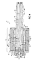
- Figure 2 is a representative section view of the valve taken along line 2-2 in Figure 1;
- Figures 3A through 3C are schematic diagrams of a relationship between a aperture in the armature and the ports at various stages of operation in the valve of Figure 1.
- Figure 4 is a section view taken along line 2-2 of Figure 1 of an alternative embodiment of the invention.
- Figures 5A through 5C are schematic diagrams of a relationship between the aperture in the armature and the ports at various stages of operation in the valve of Figure 4.
- a valve 10 having an inventive integrated structure includes a housing 12 and a valve body 14.
- the housing 12 encases other valve components and includes a casing portion 16 and a cover portion 18.
- either the casing 16 or the cover 18 can act as a magnetic pole for the valve 10, depending on the desired operation of the valve 10.
- An exposed portion 20 of the valve body 14 is configured to fit in a manifold (not shown) and has one or more openings 36b through which fluid can flow at various pressures.
- FIG 2 is a section view of the valve 10 taken along line 2-2 of Figure 1.
- the cover portion 16 of the housing 12 acts as the magnetic pole for the valve 10 to create an inversely proportional valve.
- the housing 12 encases an armature 30 that surrounds a hidden portion 32 of the valve body 14.
- the armature 30 has an aperture 34 that communicates with one or more ports 36 of the valve body 14 to meter fluid flow in response to changes in fluid pressure at the ports 36.
- the ports 36 each have a first opening 36a within the housing 12 and a second opening 36b outside the housing 12, allowing fluid to freely communicate through the ports 36 to and from a fluid supply (not shown), a fluid exhaust (not shown) and a manifold (not shown).
- a spring 38 also applies a biasing force on the armature 30 to push the armature 30 toward the cover 18 (toward the right in Figure 2), in the opposite direction of the force from the fluid pressure in the aperture 34.
- the armature 30 is disposed inside a non-magnetic bobbin 40, which supports a conductive winding forming a solenoid 42.
- a magnetic force having a strength that is proportional to the amount of current, and this magnetic force is applied to the armature 30 to pull the armature toward the casing 16 of the housing 12 (toward the left in the orientation shown in Figure 2).
- the position of the armature 30 is dependent on the interacting forces applied to the armature 30 by the spring 38, the magnetic force, and the hydraulic force generated by the fluid flowing through the aperture 34.
- the armature 30 will change position until these forces counterbalance each other into an equilibrium state.
- the output pressure of the valve 10 decreases as the current to the valve 10 increases.
- the fluid pressure at the outputs 36 can be controlled by changing the amount of current through the solenoid 42, which in turn changes the magnetic force on the armature 30; the movement of the armature's position will then change which internal openings 36a are covered or exposed, changing the control pressure inside the ports 36 through the valve body 14 and therefore changing the output pressure of the valve 10.
- a calibration assembly 50 is connected to the housing 12 to allow control of the tension in the spring 38 and/or the size of an air gap 52 between the casing 16, which acts as the magnetic pole in this embodiment, and the armature 30
- the calibration assembly 50 can have any desired structure and is not critical to the claimed invention.
- the calibration assembly 50 includes a first threaded portion 54 that engages with the valve body 14 to set the size of the air gap 52 and a second threaded portion 58 that engages with the first threaded portion 54 to set the spring 38 tension.
- first and second threaded portions 54, 58 are threaded in opposite directions (i.e., one has a left-hand thread and the other has a right-hand thread), and a calibration support 56 locks the first threaded portion 54 and the second threaded portion 58 together.
- a spring,washer 60 creates physical resistance against movement of the first threaded portion 54 to set the size of the air gap 52.
- a clip 62 is attached to the valve body 14 to hold the valve 10 assembly together.
- FIGS 3A through 3C show the armature 30 in various operating states. Because the valve 10 in this embodiment is an inversely proportional valve, the fluid pressure at the valve output 36 decreases as the current applied to the solenoid 42 increases.
- the port openings 36a in the hidden portion 32 of the valve body 14 include a supply port P1, a control port P2, and an exhaust port P3.
- the control port P2 is always fluidically coupled to the armature 30 via the aperture 34 and controls the output pressure of the valve 10.
- the aperture 34 is configured so that the control port P2 is connectable primarily to either the supply port P1 or the exhaust port P3.
- the magnetic force F magnet applied to the armature 30 is changed, causing the armature 30 to move along the valve body 14.
- This causes the aperture 34 to connect the control port P2 to either the supply port P1 or exhaust port P3, depending on whether the fluid pressure is to be increased or decreased at the output 36b of the control port P2.
- the changing fluid pressure brings the armature 30 back to an equilibrium state.
- Figure 3A shows the armature in a steady state position.
- F magnet + F fluid F spring and therefore the aperture 34 only exposes the control port P2, substantially covering the supply port P1 and the exhaust port P3 so that only leakage fluid can enter or exit the aperture 34, allowing the armature 30 to maintain its steady state position.
- the magnetic force F magnet is zero, and the fluid force F fluid is equal to the spring force F spring .
- the spring force is calibrated via the calibration assembly 50 based on the desired fluid force that will be considered "steady state" when the solenoid is de-energized.
- FIGS 4 and 5A through 5C show the structure and operation of a proportional valve 10 according to one embodiment of the invention.
- the cover portion 18 of the housing 12 serves as the magnetic pole.
- the pole orientation and the spring tension causes the valve 10 to operate so that when the output pressure of the valve 10 increases as the current to the valve 10 increases.
- the steady state position of the armature 30 relative to the inputs 36a of the ports 36 as shown in Figure 5A is conceptually the same as the position shown in Figure 3A, with the aperture 34 in the armature fluidically coupled to the control port P2, with possible leakage coming through the supply port P1 and the exhaust port P3 to maintain the selected fluid pressure.
- the current through the solenoid 42 is increased, thereby increasing the magnetic force F magnet on the armature 30.
- the combined spring force F spring and increased magnetic force F magnet is initially greater than the fluid force F fluid , pushing the armature 30 toward the cover 18 (i.e., toward the right in Figure 4).
- the aperture 34 exposes the supply port P1 and couples it with the control port P2 ( Figure 5C). Fluid then flows through the supply port P1 into the control port P2 and is metered by the armature 30 until the increased fluid pressure F fluid compensates for the increase in the magnetic force F magnet .
- Decreasing the current through the solenoid 42 decreases the magnetic force F magnet , thereby decreasing the fluid pressure F fluid at the output 36b corresponding to the output port P2. More particularly, the reduction in the magnetic force F magnet causes the combined forces applied on the armature 30 by the magnet F magnet and the spring F spring to be less than the force applied in the opposite direction by the fluid F fluid , forcing the armature 30 toward the calibration assembly 50 (toward the left in Figure 4). This causes the aperture 34 to uncover the exhaust port P3 and couple it to the control port P2, which in turn allows fluid to drain out of the control port P2 through the aperture 34 and out the exhaust port P3 to reduce fluid pressure. The position of the aperture adjusts and meters until the fluid pressure F fluid has been reduced sufficiently to compensate for the drop in magnetic force F magnet .
- the inventive structure By configuring the armature 30 with an aperture 34 that meters fluid flow through the inputs 36a of the ports in the valve body 14, the inventive structure eliminates the need for a separate spool, bearings, and armature pin, thereby reducing the number of components in the valve 10 compared to currently known assemblies. Also, aligning the various components in the inventive valve 10 is simpler because the armature 30 is tube-shaped and fits around the valve body 14; as a result, if the armature 30 is properly aligned with the hidden portion 32 of the valve body 14 the valve 10 will work properly. This structure makes it difficult to misalign the armature 30 with the valve body 14 and also ensures that any misalignments that do occur are not magnified along the entire length of the valve body 14.
- the lack of a separate spool in the inventive valve 10 makes it impossible for any disconnection between the armature 30 and pressure control.
- dithering of the armature can be reliably conducted by simply varying the current applied to the valve; proper dithering is not dependent on the fluid pressure in the valve 10. These factors improve the valve's reliability and robustness.
- the simple configuration also makes it possible to use the same overall configuration for different valve types (i.e., proportional, inversely proportional) through minor machining modifications, reducing manufacturing complexity.
Abstract
Description
- The present invention relates to electrically operated valves, and more particularly to electrically operated solenoid valves that control fluid pressure based on the amount of current through the solenoid.
- Solenoid operated valves have found widespread usage in on-board vehicle applications for controlling hydraulic pressure and fluid flow in automatic shifting power transmissions on the vehicle. Conventional solenoid valve structures include a solenoid that receives an electrical current signal, an armature that moves in response to the signal via magnetic force, and a spool that operates in response to the armature movement to change a pressure output of the valve. A pin acts as a mechanical interface between the armature and the spool. A spring force acts on the armature as well; as a result, the position of the armature and spool, and therefore the valve pressure, depends on the counterbalance of forces in the spring, the magnetic forces on the armature, and the hydraulic pressure. Normally, the spool is continually engaged with the armature via any pressure imbalances on the spool, the spring force, or both. The spool therefore meters fluid out of the valve based on the armature position.
- Occasionally, contaminants may enter the valve. To loosen the contaminants so that they can be flushed out of the valve, a dithered signal is applied to the armature to continually oscillate the armature, and therefore the spool. However, proper valve operation requires the armature and spool to be in constant contact. Low operating pressures within the valve may cause the spool to lose contact with the armature, preventing dither in the armature from being transferred to the spool. As a result, any future movement by the spool must first overcome static friction, causing the spool to unstick itself in an uncontrolled fashion, creating undesirably rapid pressure change at the valve output.
- Also, currently known valve structures require tight manufacturing tolerances. The alignment of the pin, armature and spool are particularly delicate and must be perfectly linear and centered to ensure proper valve operation. If any one of these components is even slightly out of alignment, the valve will fail. The pin, in particular, must be perfectly aligned with the spool; however, the length of the pin and the spool causes any misalignments in the pin to be magnified at the spool. The many components in current valve assemblies makes it challenging to manufacture and introduces greater opportunities for potential valve malfunctions.
- There is a desire for a solenoid valve assembly that operates more reliably and also has a simpler construction than currently known valve assemblies.
- The present invention is directed to a solenoid valve and, method having a simplified structure that integrates the fluid metering functions of the spool in the armature, thereby eliminating the need for a separate spool, bearings and pin in the armature. The valve assembly includes an armature that is responsive to a spring force, a magnetic force generated by the solenoid, and fluid pressure in the valve. The armature has an aperture that communicates with at least one port in a valve body, The position of the differential in the armature with respect to the ports in the valve body controls the pressure of fluid exiting the outputs of the valve body. In one embodiment, the same overall valve structure can be modified by changing the position of a pole piece and the porting in the valve body to form both inversely proportional valves and directly proportional valves.
- By integrating the fluid metering functions of the spool into a single ported armature, the inventive valve assembly reduces the number of parts in the valve and simplifies the alignment of parts within the valve. Moreover, the simplified valve structure allows the same overall structure be used for different types of valves with only minor modifications.
- Figures 1 is a perspective view of a representative solenoid valve assembly;
- Figure 2 is a representative section view of the valve taken along line 2-2 in Figure 1;
- Figures 3A through 3C are schematic diagrams of a relationship between a aperture in the armature and the ports at various stages of operation in the valve of Figure 1.
- Figure 4 is a section view taken along line 2-2 of Figure 1 of an alternative embodiment of the invention; and
- Figures 5A through 5C are schematic diagrams of a relationship between the aperture in the armature and the ports at various stages of operation in the valve of Figure 4.
- Referring to Figure 1, a
valve 10 having an inventive integrated structure includes a housing 12 and avalve body 14. The housing 12 encases other valve components and includes acasing portion 16 and acover portion 18. As will be described in greater detail below, either thecasing 16 or thecover 18 can act as a magnetic pole for thevalve 10, depending on the desired operation of thevalve 10. An exposedportion 20 of thevalve body 14 is configured to fit in a manifold (not shown) and has one ormore openings 36b through which fluid can flow at various pressures. - Figure 2 is a section view of the
valve 10 taken along line 2-2 of Figure 1. In this embodiment, thecover portion 16 of the housing 12 acts as the magnetic pole for thevalve 10 to create an inversely proportional valve. The housing 12 encases anarmature 30 that surrounds ahidden portion 32 of thevalve body 14. Thearmature 30 has anaperture 34 that communicates with one ormore ports 36 of thevalve body 14 to meter fluid flow in response to changes in fluid pressure at theports 36. Theports 36 each have a first opening 36a within the housing 12 and a second opening 36b outside the housing 12, allowing fluid to freely communicate through theports 36 to and from a fluid supply (not shown), a fluid exhaust (not shown) and a manifold (not shown). The fluid pressure within theaperture 34 pushes thearmature 30 toward the casing 16 (toward the left in the orientation shown in Figure 2). Aspring 38 also applies a biasing force on thearmature 30 to push thearmature 30 toward the cover 18 (toward the right in Figure 2), in the opposite direction of the force from the fluid pressure in theaperture 34. - The
armature 30 is disposed inside anon-magnetic bobbin 40, which supports a conductive winding forming asolenoid 42. As is known in the art, current flow through thesolenoid 42 generates a magnetic force having a strength that is proportional to the amount of current, and this magnetic force is applied to thearmature 30 to pull the armature toward thecasing 16 of the housing 12 (toward the left in the orientation shown in Figure 2). As a result, the position of thearmature 30 is dependent on the interacting forces applied to thearmature 30 by thespring 38, the magnetic force, and the hydraulic force generated by the fluid flowing through theaperture 34. Thearmature 30 will change position until these forces counterbalance each other into an equilibrium state. In this inversely proportional valve example, the spring force is equal to the sum of the magnetic force and the fluid force applied to thearmature 30, or Fmagnet + Ffluid = Fspring. In this example, the output pressure of thevalve 10 decreases as the current to thevalve 10 increases. - As a result, the fluid pressure at the
outputs 36 can be controlled by changing the amount of current through thesolenoid 42, which in turn changes the magnetic force on thearmature 30; the movement of the armature's position will then change whichinternal openings 36a are covered or exposed, changing the control pressure inside theports 36 through thevalve body 14 and therefore changing the output pressure of thevalve 10. - A
calibration assembly 50 is connected to the housing 12 to allow control of the tension in thespring 38 and/or the size of anair gap 52 between thecasing 16, which acts as the magnetic pole in this embodiment, and thearmature 30 Thecalibration assembly 50 can have any desired structure and is not critical to the claimed invention. In one embodiment, thecalibration assembly 50 includes a first threadedportion 54 that engages with thevalve body 14 to set the size of theair gap 52 and a second threadedportion 58 that engages with the first threadedportion 54 to set thespring 38 tension. In one embodiment, the first and second threadedportions portion 54 and the second threadedportion 58 together. - Near the
cover portion 18 of the housing 12, a spring,washer 60 creates physical resistance against movement of the first threadedportion 54 to set the size of theair gap 52. Aclip 62 is attached to thevalve body 14 to hold thevalve 10 assembly together. - Figures 3A through 3C show the
armature 30 in various operating states. Because thevalve 10 in this embodiment is an inversely proportional valve, the fluid pressure at thevalve output 36 decreases as the current applied to thesolenoid 42 increases. - The
port openings 36a in thehidden portion 32 of thevalve body 14 include a supply port P1, a control port P2, and an exhaust port P3. The control port P2 is always fluidically coupled to thearmature 30 via theaperture 34 and controls the output pressure of thevalve 10. As can be seen in the figures, theaperture 34 is configured so that the control port P2 is connectable primarily to either the supply port P1 or the exhaust port P3. To change the output pressure, the magnetic force Fmagnet applied to thearmature 30 is changed, causing thearmature 30 to move along thevalve body 14. This, in turn, causes theaperture 34 to connect the control port P2 to either the supply port P1 or exhaust port P3, depending on whether the fluid pressure is to be increased or decreased at theoutput 36b of the control port P2. The changing fluid pressure brings thearmature 30 back to an equilibrium state. - Figure 3A shows the armature in a steady state position. At this point, Fmagnet + Ffluid = Fspring and therefore the
aperture 34 only exposes the control port P2, substantially covering the supply port P1 and the exhaust port P3 so that only leakage fluid can enter or exit theaperture 34, allowing thearmature 30 to maintain its steady state position. If there is no current being sent through the solenoids, the magnetic force Fmagnet is zero, and the fluid force Ffluid is equal to the spring force Fspring. During manufacturing, the spring force is calibrated via thecalibration assembly 50 based on the desired fluid force that will be considered "steady state" when the solenoid is de-energized. - Referring to Figure 3B, increasing the current through the
solenoid 42 decreases the fluid pressure at the control port P2 and therefore itscorresponding output 36b. More particularly, the increasing current will increase the magnetic force Fmagnet acting on thearmature 30, causing the armature to move toward thecasing portion 16 of the housing 12 (toward the left) acting as the magnetic pole. This creates a pressure imbalance because the increased magnetic force Fmagnet causes the sum of the magnetic force Fmagnet and the fluid force Ffluid to be greater than the counteracting spring force Fspring. The new position of thearmature 30, as shown in Figure 3B, causes theaperture 34 to be fluidically coupled to both the control port P2 and the exhaust port P3. This allows fluid contributing to the excess fluid pressure Ffluid to flow from the control port P2 into theaperture 34 and out the exhaust port P3, decreasing the fluid pressure Ffluid in the control port P2 and causing thearmature 30 to move and meter (i.e., cover/uncover the supply port P1 and/or the exhaust port P3 to varying degrees) in response to the changing fluid pressure. The fluid pressure Ffluid continues to decrease until it compensates for the increased magnetic force Fmagnet to equalize the spring force Fspring. At this point, the armature has metered so that thearmature 30 covers the exhaust port P3 nearly completely and is at the steady state (Figure 3A) at the new fluid pressure. - When the current is reduced or shut off, the magnetic force Fmagnet will go down as well. As a result, the imbalance between the fluid force Ffluid and the spring force Fspring will cause the fluid force within the
aperture 34 to initially push thearmature 30 toward thecover portion 18 of the housing 12 (because the spring force Fspring at this point will be greater than the sum of the magnetic force Fmagnet and the fluid pressure Ffluid). This causes theaperture 34 in the armature to fluidically couple the control port P2 with the supply port P1, as shown in Figure 3C. Additional fluid flows from the supply port P1 into theaperture 34 and increase the fluid pressure Ffluid at the control port P2, causing thearmature 30 to move and meter the fluid flow until the fluid pressure in the aperture compensates for the decreased magnetic force Fmagnet to equalize the spring force Fspring. Once this occurs, thearmature 30 will again reach the steady state position in Figure 3A, substantially closing off the supply port P1 to maintain the fluid pressure corresponding to the amount of current through thesolenoid 42.. - The examples described above focus on an inversely proportional valve assembly, but the same inventive concept can be used in a proportional valve. Figures 4 and 5A through 5C show the structure and operation of a
proportional valve 10 according to one embodiment of the invention. In this embodiment, thecover portion 18 of the housing 12 serves as the magnetic pole. In this embodiment, thevalve 10 operates according to the equation Fmagnet = Fspring + Ffluid. The pole orientation and the spring tension causes thevalve 10 to operate so that when the output pressure of thevalve 10 increases as the current to thevalve 10 increases. - The steady state position of the
armature 30 relative to theinputs 36a of theports 36 as shown in Figure 5A is conceptually the same as the position shown in Figure 3A, with theaperture 34 in the armature fluidically coupled to the control port P2, with possible leakage coming through the supply port P1 and the exhaust port P3 to maintain the selected fluid pressure. To increase the fluid pressure, the current through thesolenoid 42 is increased, thereby increasing the magnetic force Fmagnet on thearmature 30. As a result, the combined spring force Fspring and increased magnetic force Fmagnet is initially greater than the fluid force Ffluid, pushing thearmature 30 toward the cover 18 (i.e., toward the right in Figure 4). As a result, theaperture 34 exposes the supply port P1 and couples it with the control port P2 (Figure 5C). Fluid then flows through the supply port P1 into the control port P2 and is metered by thearmature 30 until the increased fluid pressure Ffluid compensates for the increase in the magnetic force Fmagnet. - Decreasing the current through the
solenoid 42 decreases the magnetic force Fmagnet, thereby decreasing the fluid pressure Ffluid at theoutput 36b corresponding to the output port P2. More particularly, the reduction in the magnetic force Fmagnet causes the combined forces applied on thearmature 30 by the magnet Fmagnet and the spring Fspring to be less than the force applied in the opposite direction by the fluid Ffluid, forcing thearmature 30 toward the calibration assembly 50 (toward the left in Figure 4). This causes theaperture 34 to uncover the exhaust port P3 and couple it to the control port P2, which in turn allows fluid to drain out of the control port P2 through theaperture 34 and out the exhaust port P3 to reduce fluid pressure. The position of the aperture adjusts and meters until the fluid pressure Ffluid has been reduced sufficiently to compensate for the drop in magnetic force Fmagnet. - By configuring the
armature 30 with anaperture 34 that meters fluid flow through theinputs 36a of the ports in thevalve body 14, the inventive structure eliminates the need for a separate spool, bearings, and armature pin, thereby reducing the number of components in thevalve 10 compared to currently known assemblies. Also, aligning the various components in theinventive valve 10 is simpler because thearmature 30 is tube-shaped and fits around thevalve body 14; as a result, if thearmature 30 is properly aligned with the hiddenportion 32 of thevalve body 14 thevalve 10 will work properly. This structure makes it difficult to misalign thearmature 30 with thevalve body 14 and also ensures that any misalignments that do occur are not magnified along the entire length of thevalve body 14. - Also, the lack of a separate spool in the
inventive valve 10 makes it impossible for any disconnection between thearmature 30 and pressure control. As a result, dithering of the armature can be reliably conducted by simply varying the current applied to the valve; proper dithering is not dependent on the fluid pressure in thevalve 10. These factors improve the valve's reliability and robustness. The simple configuration also makes it possible to use the same overall configuration for different valve types (i.e., proportional, inversely proportional) through minor machining modifications, reducing manufacturing complexity. - Although the invention has hereinabove been described with respect to the illustrated embodiments, it will be understood that the invention is capable of modification and variation and is limited only by the following claims.
Claims (19)
- A solenoid operated valve (10), comprising:a valve body (14) having at least one port (36) formed therein to form a fluid path, said at least one port having a first opening (36a) and a second opening (36b);a solenoid (42) that generates a magnetic force; andan armature (30) that surrounds a portion of the valve body, wherein the armature is movable in response to the magnetic force along at least a portion of the valve body, the armature having an aperture (34) that selectively couples with the first opening to control a fluid force through said at least one port.
- The valve of claim 1, further comprising a spring (38) that applies a spring force on the armature.
- The valve of claim 2, wherein the armature moves to equalize the spring force with a sum of the magnetic force and the fluid force.
- The valve of claim 2, wherein the armature moves to equalize the fluid force with a sum of the magnetic force and the spring force.
- The valve of claim 1, further comprising a housing (12) having a casing (16) that covers the solenoid and the armature and a cover (18).
- The valve of claim 1, wherein at least one of the casing and the cover is a magnetic pole in the valve.
- A solenoid operated valve (10), comprising:a valve body (14) having a control port (P2), a supply port (P1), and an exhaust port (P3) formed therein;a solenoid (42) that generates a magnetic force;an armature (30) disposed inside the solenoid and that surrounds a portion of the valve body, wherein the armature is movable in response to the magnetic force along at least a portion of the valve body, the armature having an aperture (34) that selectively couples with at least one of the control port, supply port, and exhaust port to control a fluid force through the control port;a spring (38) that applies a spring force on the armature, wherein a position of the armature is controlled by a combination of the magnetic force, the fluid force, and the spring force; anda housing (12) having a casing that covers the solenoid and the armature and a cover, wherein at least one of the casing and the cover is a magnetic pole in the valve.
- The valve of claim 7, wherein the valve is an inversely proportional valve, wherein:the casing is the magnetic pole; andthe armature moves to equalize the spring force with a sum of the magnetic force and the spring force.
- The valve of claim 8, wherein the fluid force causes the aperture to couple the control port with the supply port when the magnetic force decreases and wherein the fluid force causes the aperture to couple the control port with the exhaust port when the magnetic force increases.
- The valve of claim 7, wherein the valve is a directly proportional valve, wherein:the cover is the magnetic pole; andthe armature moves to equalize the spring force with a sum of the magnetic force and the fluid force.
- The valve of claim 10, wherein the fluid force causes the aperture to couple the control port with the supply port when the magnetic force increases and wherein the fluid force causes the aperture to couple the control port with the exhaust port when the magnetic force decreases.
- The valve of claim 7, further comprising a calibration assembly (50) that sets at least one of a spring force and an air gap in the valve.
- A method of manufacturing a solenoid operated valve (10), comprising:forming a valve body (14) having a control port (P2), a supply port (P1), and an exhaust port (P3) formed therein;placing an armature (30) to surround a portion of the valve body; andplacing a solenoid (42) to surround at least a portion of the armature, wherein the solenoid generates a magnetic force,wherein the armature (30) is movable in response to the magnetic force along at least a portion of the valve body, the armature having an aperture (34) that selectively couples with at least one of the control port, supply port, and exhaust port to control a fluid force through the control port.
- The method of claim 13, further comprising coupling the armature with a spring that applies a spring force on the armature, wherein a position of the armature is controlled by a combination of the magnetic force, the fluid force, and the spring force.
- The method of claim 14, further comprising placing the portion of the valve body, the armature, the solenoid, and the spring in a housing, wherein the housing leaves a second portion of the valve body exposed.
- The method of claim 15, wherein the housing comprises a casing (16) and a cover (18), and wherein the method further comprising magnetizing at least one of the casing and the cover to form a magnetic pole.
- The method of claim 14, further comprising:attaching a calibration assembly (50) to the valve; andadjusting at least one of an air gap (52) and the spring force with the calibration assembly.
- The method of claim 17, wherein the valve is an inversely proportional valve, and wherein the adjusting step comprises adjusting the spring force to be equal to a sum of the fluid force and the magnetic force at steady state.
- The method of claim 17, wherein the valve is a directly proportional valve, and wherein the adjusting step comprises adjusting the spring force to be equal to a difference between the magnetic force and the fluid force at steady state.
Applications Claiming Priority (1)
| Application Number | Priority Date | Filing Date | Title |
|---|---|---|---|
| US11/227,054 US7556062B2 (en) | 2005-09-15 | 2005-09-15 | Solenoid valve with integrated structure |
Publications (2)
| Publication Number | Publication Date |
|---|---|
| EP1764535A2 true EP1764535A2 (en) | 2007-03-21 |
| EP1764535A3 EP1764535A3 (en) | 2007-12-26 |
Family
ID=37440757
Family Applications (1)
| Application Number | Title | Priority Date | Filing Date |
|---|---|---|---|
| EP20060018958 Withdrawn EP1764535A3 (en) | 2005-09-15 | 2006-09-11 | Solenoid valve with integrated structure |
Country Status (3)
| Country | Link |
|---|---|
| US (1) | US7556062B2 (en) |
| EP (1) | EP1764535A3 (en) |
| JP (1) | JP2007078188A (en) |
Cited By (2)
| Publication number | Priority date | Publication date | Assignee | Title |
|---|---|---|---|---|
| DE102008044790A1 (en) | 2008-08-28 | 2010-03-04 | Robert Bosch Gmbh | way valve |
| WO2017144860A1 (en) * | 2016-02-26 | 2017-08-31 | Norgren Limited | Flow divider valve |
Families Citing this family (5)
| Publication number | Priority date | Publication date | Assignee | Title |
|---|---|---|---|---|
| US20090151790A1 (en) * | 2007-12-12 | 2009-06-18 | Baker Hughes Incorporated | Electro-magnetic multi choke position valve |
| DE102008013602B4 (en) * | 2008-03-11 | 2019-07-04 | Robert Bosch Gmbh | Method for driving a plurality of valves and control block with a plurality of valves |
| USD753795S1 (en) * | 2014-05-05 | 2016-04-12 | Buschjost GmbH | Valve |
| JP7308642B2 (en) * | 2019-03-29 | 2023-07-14 | 日立Astemo株式会社 | Flow switching valve |
| DE102019210488A1 (en) | 2019-07-16 | 2021-01-21 | Robert Bosch Gmbh | Valve piston and valve with the valve piston |
Citations (1)
| Publication number | Priority date | Publication date | Assignee | Title |
|---|---|---|---|---|
| US5488973A (en) | 1993-11-19 | 1996-02-06 | Unisia Jecs Corporation | Structure for control valve |
Family Cites Families (11)
| Publication number | Priority date | Publication date | Assignee | Title |
|---|---|---|---|---|
| US3129724A (en) * | 1960-08-13 | 1964-04-21 | Erich Herion | Solenoid controlled distributing valve |
| US3703165A (en) * | 1971-07-15 | 1972-11-21 | Gen Motors Corp | Fuel tank vent control |
| US4339109A (en) * | 1979-04-04 | 1982-07-13 | Aisin Seiki Kabushiki Kaisha | Electromagnetically operated valve unit |
| US4513780A (en) * | 1984-02-08 | 1985-04-30 | General Motors Corporation | Solenoid valve |
| US4917150A (en) * | 1988-07-29 | 1990-04-17 | Colt Industries Inc. | Solenoid operated pressure control valve |
| US5064166A (en) * | 1990-09-20 | 1991-11-12 | Ford Motor Company | Solenoid valve with high flow capacity and low energy consumption |
| US5076326A (en) | 1990-10-15 | 1991-12-31 | Coltec Industries Inc. | Electromagnetically operated fluid control valve |
| IT1260476B (en) * | 1992-05-28 | 1996-04-09 | ELECTROMAGNETIC ACTUATOR DEVICE IN PARTICULAR FOR VALVES AND ELECTRO-HYDRAULIC APPLICATIONS | |
| US5445189A (en) * | 1992-11-20 | 1995-08-29 | Unisia Jecs Corporation | Structure for control valve |
| US5419369A (en) * | 1994-02-28 | 1995-05-30 | Coltec Industries Inc. | Solenoid operated pressure control valve |
| JPH084937A (en) * | 1994-06-17 | 1996-01-12 | Unisia Jecs Corp | Fluid control valve |
-
2005
- 2005-09-15 US US11/227,054 patent/US7556062B2/en not_active Expired - Fee Related
-
2006
- 2006-09-11 EP EP20060018958 patent/EP1764535A3/en not_active Withdrawn
- 2006-09-14 JP JP2006249509A patent/JP2007078188A/en active Pending
Patent Citations (1)
| Publication number | Priority date | Publication date | Assignee | Title |
|---|---|---|---|---|
| US5488973A (en) | 1993-11-19 | 1996-02-06 | Unisia Jecs Corporation | Structure for control valve |
Cited By (3)
| Publication number | Priority date | Publication date | Assignee | Title |
|---|---|---|---|---|
| DE102008044790A1 (en) | 2008-08-28 | 2010-03-04 | Robert Bosch Gmbh | way valve |
| WO2010022868A1 (en) * | 2008-08-28 | 2010-03-04 | Robert Bosch Gmbh | Directional control valve |
| WO2017144860A1 (en) * | 2016-02-26 | 2017-08-31 | Norgren Limited | Flow divider valve |
Also Published As
| Publication number | Publication date |
|---|---|
| JP2007078188A (en) | 2007-03-29 |
| EP1764535A3 (en) | 2007-12-26 |
| US20070056645A1 (en) | 2007-03-15 |
| US7556062B2 (en) | 2009-07-07 |
Similar Documents
| Publication | Publication Date | Title |
|---|---|---|
| US7556062B2 (en) | Solenoid valve with integrated structure | |
| EP1186816B1 (en) | Solenoid valve | |
| KR101783540B1 (en) | Solenoid operated fluid control valve | |
| KR102113102B1 (en) | Direct acting solenoid actuator | |
| JP5615286B2 (en) | Solenoid valve | |
| KR20010006364A (en) | Electromagnetic hydraulic valve | |
| US7118088B2 (en) | Fluid control valve | |
| US7938143B2 (en) | Fluid pressure control apparatus | |
| JP4141375B2 (en) | 3-way bleed proportional solenoid valve | |
| JP2004504566A (en) | Proportional pressure control valve | |
| US6167906B1 (en) | Bi-directional flow control valve | |
| US20040129322A1 (en) | Pressure control valve for controlling two pressure load paths | |
| WO2020054837A1 (en) | Linear solenoid valve | |
| JP4492649B2 (en) | Bleed valve device | |
| EP0385286B1 (en) | Variable force solenoid pressure regulator for electronic transmission controller | |
| JP2007100829A (en) | Valve device | |
| US20090057594A1 (en) | Bleed valve apparatus | |
| US20110131947A1 (en) | Trim valves for modulating fluid flow | |
| US20180355993A1 (en) | Hydraulic valve configuration for nh vbs with a nl solenoid | |
| JPH084934A (en) | Solenoid valve for fluid control | |
| US20050056034A1 (en) | Flow-regulating expansion valve | |
| JP4110894B2 (en) | Solenoid valve | |
| KR100578086B1 (en) | Magnetically levitated, electromagnetically actuated valve for fluidic mass flow control | |
| JP2848812B2 (en) | Electric expansion valve | |
| JP4044804B2 (en) | Control valve |
Legal Events
| Date | Code | Title | Description |
|---|---|---|---|
| PUAI | Public reference made under article 153(3) epc to a published international application that has entered the european phase |
Free format text: ORIGINAL CODE: 0009012 |
|
| AK | Designated contracting states |
Kind code of ref document: A2 Designated state(s): AT BE BG CH CY CZ DE DK EE ES FI FR GB GR HU IE IS IT LI LT LU LV MC NL PL PT RO SE SI SK TR |
|
| AX | Request for extension of the european patent |
Extension state: AL BA HR MK YU |
|
| PUAL | Search report despatched |
Free format text: ORIGINAL CODE: 0009013 |
|
| AK | Designated contracting states |
Kind code of ref document: A3 Designated state(s): AT BE BG CH CY CZ DE DK EE ES FI FR GB GR HU IE IS IT LI LT LU LV MC NL PL PT RO SE SI SK TR |
|
| AX | Request for extension of the european patent |
Extension state: AL BA HR MK YU |
|
| 17P | Request for examination filed |
Effective date: 20080521 |
|
| 17Q | First examination report despatched |
Effective date: 20080702 |
|
| AKX | Designation fees paid |
Designated state(s): AT BE BG CH CY CZ DE DK EE ES FI FR GB GR HU IE IS IT LI LT LU LV MC NL PL PT RO SE SI SK TR |
|
| STAA | Information on the status of an ep patent application or granted ep patent |
Free format text: STATUS: THE APPLICATION IS DEEMED TO BE WITHDRAWN |
|
| 18D | Application deemed to be withdrawn |
Effective date: 20100331 |