EP1764530A1 - Drive unit with speed reducer - Google Patents
Drive unit with speed reducer Download PDFInfo
- Publication number
- EP1764530A1 EP1764530A1 EP05765101A EP05765101A EP1764530A1 EP 1764530 A1 EP1764530 A1 EP 1764530A1 EP 05765101 A EP05765101 A EP 05765101A EP 05765101 A EP05765101 A EP 05765101A EP 1764530 A1 EP1764530 A1 EP 1764530A1
- Authority
- EP
- European Patent Office
- Prior art keywords
- rotor
- gear
- flexible
- teeth
- drive unit
- Prior art date
- Legal status (The legal status is an assumption and is not a legal conclusion. Google has not performed a legal analysis and makes no representation as to the accuracy of the status listed.)
- Granted
Links
Images


Classifications
-
- F—MECHANICAL ENGINEERING; LIGHTING; HEATING; WEAPONS; BLASTING
- F16—ENGINEERING ELEMENTS AND UNITS; GENERAL MEASURES FOR PRODUCING AND MAINTAINING EFFECTIVE FUNCTIONING OF MACHINES OR INSTALLATIONS; THERMAL INSULATION IN GENERAL
- F16H—GEARING
- F16H49/00—Other gearings
- F16H49/001—Wave gearings, e.g. harmonic drive transmissions
-
- H—ELECTRICITY
- H02—GENERATION; CONVERSION OR DISTRIBUTION OF ELECTRIC POWER
- H02K—DYNAMO-ELECTRIC MACHINES
- H02K41/00—Propulsion systems in which a rigid body is moved along a path due to dynamo-electric interaction between the body and a magnetic field travelling along the path
- H02K41/06—Rolling motors, i.e. motors having the rotor axis parallel to the stator axis and following a circular path as the rotor rolls around the inside or outside of the stator ; Nutating motors, i.e. having the rotor axis parallel to the stator axis inclined with respect to the stator axis and performing a nutational movement as the rotor rolls on the stator
-
- F—MECHANICAL ENGINEERING; LIGHTING; HEATING; WEAPONS; BLASTING
- F16—ENGINEERING ELEMENTS AND UNITS; GENERAL MEASURES FOR PRODUCING AND MAINTAINING EFFECTIVE FUNCTIONING OF MACHINES OR INSTALLATIONS; THERMAL INSULATION IN GENERAL
- F16H—GEARING
- F16H49/00—Other gearings
- F16H49/001—Wave gearings, e.g. harmonic drive transmissions
- F16H2049/003—Features of the flexsplines therefor
-
- Y—GENERAL TAGGING OF NEW TECHNOLOGICAL DEVELOPMENTS; GENERAL TAGGING OF CROSS-SECTIONAL TECHNOLOGIES SPANNING OVER SEVERAL SECTIONS OF THE IPC; TECHNICAL SUBJECTS COVERED BY FORMER USPC CROSS-REFERENCE ART COLLECTIONS [XRACs] AND DIGESTS
- Y10—TECHNICAL SUBJECTS COVERED BY FORMER USPC
- Y10T—TECHNICAL SUBJECTS COVERED BY FORMER US CLASSIFICATION
- Y10T74/00—Machine element or mechanism
- Y10T74/19—Gearing
Definitions
- the present invention relates to a drive unit with reducer.
- a harmonic drive gearing which serves as a reducer to be used in a conventional drive unit, has a configuration as shown in FIG.12 (see patent literature 1). That is, in this conventional unit, a flex spline 30 is positioned so as to surround a wave generator 40, which has an outer peripheral surface that is formed to an elliptical shape, across a flexible bearing 50. Also, a circular spline 20, which has a circular inner peripheral surface, is positioned at the outside of the flex spline 30.
- Inner teeth are formed on the inner peripheral surface of the circular spline 20
- outer teeth, which are engageable with the inner teeth of the circular spline 20 are formed on an outer peripheral surface of the flex spline 30, and the flex spline 30 is enabled to deflect in radial directions.
- the number of teeth of the flex spline 30 is set to be slightly less than the number of teeth of the circular spline 20.
- the wave generator 40 deflects the flex spline 30 via the flexible bearing 50 and makes the outer teeth of the flex spline 30 engage with the inner teeth of the circular spline 20.
- FIG. 13 is a diagram showing a joint of the leg of the leg type mobile robot.
- a first link 70 and a second link 90 are joined through a rotary supporting mechanism 91 and are enabled to rotate with respect to each other.
- a harmonic drive gearing 60 is mounted so that the rotating shaft thereof matches with the center of rotation of first link 70 and second link 90. That is, the circular spline 20 is fixed to the second link 90.
- the flex spline 30 is fixed, at a first rotating shaft 30a (output shaft), to the first link 70 by means of a plurality of bolts 80.
- the wave generator 40 is provided with a second rotating shaft 40a, the second rotating shaft 40a is supported in a manner enabling rotation with respect to the first rotating shaft 30a.
- a pulley 61 for transmitting a driving force, is fixed to the first rotating shaft 30a at the end section to which the first rotating shaft 30a is not provided.
- the wave generator 40 is driven. Then, the flex spline 30 is rotated at a reduced speed than the rotation speed of the pulley 61 in accordance with the rotation of the wave generator 40, and thus the first link 70 is rotated.
- the harmonic drive gearing cannot be positioned between two sets of bearings, when for example the first rotating shaft 30a is supported by two sets of bearings. This provides the problem of low degree of freedom in terms of layout.
- the pulley 61 which transmits a driving force to the wave generator 40 and is disposed on the second rotating shaft 40a, is positioned next to the wave generator 40, the size in a direction along the rotating shaft inevitably becomes large. This may make worse the usability depending on a usage.
- the present invention is intended to provide a drive unit with reducer that can improve the degree of freedom in terms of layout and can provide the improved response.
- the first aspect of the present invention relates to a harmonic drive gearing which has: a circular rigid gear, having outer teeth formed on an outer peripheral surface; an annular flexible gear, positioned at the outside of the rigid gear, having an inner peripheral length that is greater than the outer peripheral length of the rigid gear, and having inner teeth, which are engageable with the outer teeth of the rigid gear, formed on an inner peripheral surface; and a wave generator, deflecting the flexible gear in radial directions to make the inner teeth of the flexible gear engage with the outer teeth of the rigid gear and moving the engagement positions, at which the flexible gear is deflected, in a circumferential direction, and the wave generator is a rotor of a motor.
- the second aspect of the present invention relates to a drive unit with reducer that has: a circular rigid gear, having outer teeth formed on an outer peripheral surface; an annular flexible gear, positioned at the outer side of the rigid gear, having an inner peripheral length that is greater than the outer peripheral length of the rigid gear, and having inner teeth, which are engageable with the outer teeth of the rigid gear, formed on an inner peripheral surface; and a wave generator, deflecting the flexible gear in radial directions to make the inner teeth of the flexible engage with the outer teeth of the rigid gear and moving the engagement positions, at which the flexible gear is deflected, in a circumferential direction.
- the wave generator is a rotating member, which is positioned at the outside of the flexible gear in a manner enabling rotation with respect to the flexible gear and is equipped with pressing portions that press and thereby deflect the flexible gear in radial directions, and the rotating member is a rotor of a motor.
- a stator of the motor which rotates the rotor is disposed at outer peripheral side of the rotor, and the rigid gear is joined to a first member, and is rotatably supported by a second member at both ends of the rigid gear.
- a total of two flexible gears having a cylindrical part with the same diameter are provided, and flexible gears are disposed so that one end of each of flexible gears is face to face each other, and are respectively engageable to the rigid gear, and each of flexible gears is supported at the other end thereof.
- the rotor in addition to the configuration of the first or second aspect of the invention, includes: an inner peripheral surface formed to an elliptical shape; and a plurality of magnets disposed on the inner peripheral surface, and a plurality of magnets are disposed symmetrically with respect to a major axis or minor axis of the elliptical shape.
- a deformation controller which controls the deformation of the rotor is disposed at outer periphery of the rotor.
- the rotor is adapted to cause a magnetic flux along a rotation axis of the motor, and a stator is adapted to cause the magnetic flux along the rotation axis.
- the stator is disposed facing the regions wherein a magnetic flux is caused of the rotor.
- the rigid gear is disposed at an inside
- the flexible gear is disposed at an outside of the rigid gear
- the wave generator is composed of a rotor of a motor that is disposed at an outside of the flexible gear and is rotatable with respect to the flexible gear.
- the wave generator is a rotor of the motor
- the output of the motor can be directory used as an input to a harmonic drive gearing, and thus the size of the harmonic drive gearing can be compacted.
- the rigidity at an input part of the harmonic drive gearing can be high and the response of the apparatus can be improved.
- the rotation shaft of the rigid gear is, for example, made as a hollow structure and used for an wiring of an electrical harness, since the rotation speed of the rigid gear with respect to the rotation speed of the rotor is decreased largely, the causing of damage on harnesses can be limited.
- the size in the axial direction can be made small in comparison to the conventional art.
- the rotor of the motor is positioned at outside in a radial direction than the flexible gear, it is not required to using one end or both ends of the rotation axis for the input of a driving force. Thus, this improves the degree of freedom in terms of layout in the vicinity of each end of the rotation axis.
- the wave generator is a rotor of the motor and the flexible gear is deflected mechanically by the pressing portions, the outer teeth of the rigid gear and the inner teeth of the flexible gear can be engaged reliably.
- the size of the joint of the link can be minimized while allowing high torque transmission.
- the size in a width direction of the flex spline can be wide, and further high torque transmission can be enabled.
- a torque ripple is reduced, and also flux paths are symmetrically formed.
- a magnetic resistance becomes low, and a maximum torque of the motor is improved.
- the rigidity of the wave generator can be high.
- the occurrence of an upset of a magnetic flux is not caused.
- a heat to be caused due to the upset of a magnetic flux can be controlled.
- the size of the outer diameter of the rotor can be made large irrespective of the arrangement of the stator, the rigidity of the wave generator can thus be maintained at high.
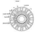
- FIG.1 is an explanatory view showing the configuration of a harmonic drive gearing, which is a basic unit of a drive unit with reducer;
- FIG.2 is an exploded perspective view of the harmonic drive gearing;
- FIG. 3 is a schematic view showing the A-A section of FIG.1.
- a harmonic drive gearing 10 mainly includes a circular spline 1, serves a rigid gear, a flex spline 2, positioned at the outside of the circular spline 1, and a pulley 3, positioned at the outside of the flex spline 2.
- the circular spline 1 has outer teeth 1a formed on an outer peripheral surface at the end section of a small-diameter portion, and has a through hole at a central portion thereof.
- the flex spline 2 is a cylindrical member having flexibility that enables deformation in a radial direction.
- the flex spline 2 has inner teeth 2a, which are engageable with outer teeth 1a, on the inner peripheral surface thereof, and has a rigid flange 2b at an end portion thereof.
- the position where the flange 2b is formed is the end position opposite to the inner teeth 2a.
- Outer teeth 1a of the circular spline 1 are set to be less in number than the inner teeth 2a of the flex spline 2.
- the pulley 3 is provided with a groove, to which a belt 9 is fitted, at a circular peripheral surface thereof, and an inner peripheral surface of the pulley 3 is formed to an elliptical shape whose center is the same as that of the outer peripheral surface of the pulley 3.
- the pulley 3 deflects the flex spline 2 through a flexible bearing 4, and fits inner teeth 2a of the flex spline 2 to outer teeth 1a of the circular spline 1 at minor axis portions of the pulley 3.
- the minor axis portions thus function as pressing portions that press the flex spline 2 in a radial direction and thereby deflect the flex spline 2.
- the pulley 3 thus serves not just the function of a pulley for transmitting a driving force but also serves the function of a wave generator in the harmonic drive gearing.
- a pulley supporting ring 6 and a link 8 are connected across the flange 2b by a plurality of bolts 8 that are aligned in a circumferential direction.
- the flange 2b serves as a fixed end and the region where inner teeth 2a are provided is adapted to deflect in a radial direction.
- a pulley supporting ring 6 supports the pulley 3 via a first bearing 5
- the link 8 supports the circular spline 1 via a second bearing 7.
- the circular spline 1 can be rotated relative to the flex spline 2. Meanwhile, the pulley 3 can rotate while deflecting the outer peripheral surface of the flex spline 2 via the flexible bearing 4. That is, the pulley 3, the flex spline 2, and the circular spline 1 can thus be rotated relatively and independently while maintaining a predetermined relationship with each other.
- the harmonic drive gearing of this embodiment can be used as a reducer or a speed-increasing gear. Additionally, by using one of these three rotating elements as an output and using remainder of rotating elements as an input, the harmonic drive gearing of this embodiment can provide the function of a differential mechanism.
- FIG.4A to FIG.4C shows diagrams illustrating the operation in the case where the circular spline is driven by applying a driving force to the pulley while keeping the flex spline fixed.
- teeth m of the circular spline 1 and teeth n of the flex spline 2 are engaged at minor axis portions of the inner peripheral surface of the pulley 3.
- engagement point "a” is rotated by 90 degrees in the same manner as the minor axis portion of the inner peripheral surface of the pulley 3 as shown in FIG. 4B.
- teeth m and teeth n become disengaged.
- engagement point "a" is likewise rotated by 180 degrees.
- teeth n of the flex spline 2 become engaged again with teeth of the circular spline 1, since the number of teeth of the circular spline 1 is less than that of the flex spline 2, teeth m of the circular spline 1 will be shifted from teeth n.
- the pulley 3 is positioned at the outermost periphery and the circular spline 1, by which the rotation speed is decreased with respect to the pulley 3, is positioned at the central portion.
- the rotating shaft of circular spline 1 may, for example, be made a hollow structure for installing therein an electrical harness.
- the driving force can be output from the circular spline 1 disposed at the central portion.
- the disposing position of the harmonic drive gearing 10 with respect to the output shaft can thus be set not just at an end portion of the output shaft but at an inner side as well.
- a driving force can be output from the output shaft that extends from both sides of the harmonic drive gearing, when the position of the harmonic drive gearing 10 is nearer to the middle than the end of the output shaft.
- FIG.5 is a sectional view showing the configuration of the drive unit with reducer.
- FIG. 6 is a schematic view showing the B-B section of FIG. 1.
- a downsized apparatus in which a power source is put together with a reducer can be configured, by using the rotor of a motor as the pulley 3 and by outputting directory a driving force given by the motor after reducing the speed.
- a flex spline 2' having inner teeth 2a', is disposed at the outside of a circular spline 1', having outer teeth 1a', and a rotor 16, which is an example of a rotation axis of the motor, is disposed at the outside of flex spline 2' across flexible bearing 4.
- the rotor of this embodiment produces a rotation by receiving a magnetic force, e.g. an attractive or repulsive force, that is caused between the rotor and a stator which is disposed coaxially with respect to the rotor.
- a magnetic force e.g. an attractive or repulsive force
- a permanent magnet or an electric magnet is provided to the rotor, and interacts with the stator facing to this rotor.
- An inner peripheral surface of the rotor 16 is formed to an elliptical shape and the rotor 16 deflects the flex spline 2' with its minor axis portions to make the inner teeth 2a' of the flex spline 2' engage with outer teeth 1a' of the circular spline 1' . That is, the rotor 16 functions as a wave generator, like the pulley 3 of the above-described harmonic drive gearing 10.
- the circular spline 1' is rotatably supported by a link 8' via a second bearing 7', and the flex spline 2' is fixed by bolts 8a with its flange being sandwiched between the wall surfaces of the link 8' and a casing 15.
- the rotor 16 is rotatably supported by the casing 15 via pair of first bearings 5.
- a stator 17 is disposed at the outside of the rotor 16 and is fixed to the casing 15.
- a plurality of salient poles are formed along a circumferential direction of the stator 17 and a coil 17a is wound around each of the salient pole. By successively supplying electricity to these coils 17a, a rotating magnetic field across the rotor 16 can be formed.
- the rotor 16 has a plurality of permanent magnets 16a disposed at equal intervals along the circumferential direction, and the rotor 16 can thus rotate upon receiving a driving force by magnetic attractive or repulsive force with respect to the stator 17.
- An encoder 18, which detects the rotation speed of the rotor 16, is disposed at an end side in a longitudinal direction of the circular spline 1' .
- a rotating disk 18a of the encoder 18 is rotatably supported by casing 15 via a third bearing 19 and is connected to the rotor 16.
- the drive unit 10' with reducer has a configuration as described above, and the rotor 16 of this unit is driven by successively supplying electricity to respective coils 17a of the stator 17.
- the engagement points between the circular spline 1' and the flex spline 2' are moved in a circumferential direction, and the circular spline 1' is thus driven in a speed-reduced manner.
- the rotor 16 thus has a function of a wave generator and also makes up a motor along with stator 17 and provides the function of an output shaft that outputs the driving force of the motor, the driving force can be output directly upon being speed-reduced.
- the drive unit 10' with reducer benefits as follows can be obtained. That is, firstly, since the motor is not disposed at the end of the shaft and a coreless type motor is adopted and is disposed at an outer peripheral side, the length in a axial direction can be shortened.
- the conventional harmonic drive gearing which consists of a flexible gear with outer teeth, since the motor is too small in comparison to an output of the harmonic drive gearing if the wave generator is integrated with the rotor (outer rotor), the apparatus is not suitable for practical use.
- the rotor since the rotor itself functions as the wave generator and is not joined with the wave generator through the axis, it can be considered that an elastic element to the rotator does not exist. Thus, the response can be improved by making higher the speed loop gain. Furthermore, since the rotor has a cylindrical shape and is large in diameter, this provides a high torsional rigidity and hereby a response becomes good.
- the motor is made as a hollow structure and has a wide surface area, a superior cooling capacity and a keeping of high torque are expected.
- the assembling is completed by a fastening after the insertion of integrated parts into the link, which has the circular spline.
- the number of parts and the number of man-hour to be required for assembling can be decreased, and hereby a reducing of cost is enabled.
- a key for preventing the rotation has been used when joining each shaft of the motor and wave generator. Since this key is not required in the drive unit 10' with reducer, the occurrence of rattling due to a fatigue of a groove of key can be prevented. Thereby, the rattling on the torque transmission path from the rotor to the wave generator can be zero. Also, a response of the wave generator can be improved as described above, and noise decreasing and improved durability can be expected.
- the joining method which uses a tapered shaft and a tapered housing and requires sufficient accuracy, has been done, when joining each shaft of the motor and wave generator.
- the drive unit 10' with reducer a treatment of tapering is not required, and the reduction of the number of man-hour and the reducing of cost are thus enabled.
- the degree of freedom in terms of layout of the drive unit with reducer can be improved.
- FIG.7 is an explanatory view showing a positional layout of the drive unit with reducer.
- the position of the harmonic drive gearing is limited to an end portion of output shaft 24 (first rotating shaft 30a).
- the output shaft can thus be set only at one side with such an arrangement.
- the position of the harmonic drive gearing can be set not only at an end portion but also between bearings 21, 22, and 23 that support the output shaft 24 (rotating shaft of circular spline 1) as illustrated.
- the degree of freedom in terms of layout can be improved.
- the inner peripheral surface of the rotor 16 is made elliptical and the flex spline 2 is deflected by the minor axis portions, the inner peripheral surface does not necessarily have to be of elliptical shape, and for example as shown in FIG.8, protrusions 16b' and 16b' may be formed as pressing portions at two opposing locations of a circular inner peripheral surface and the flex spline 2 may be deflected by means of protrusions 16b' and 16b'.
- protrusions 16b' and 16b' cause the engagement points of the flex spline 2 and the circular spline 1' to move to thereby enable the rotation speed of the circular spline 1 to be reduced.
- the end surface of each of protrusions 16b' and 16b' may be a portion of a circle or a portion of an ellipse. As a matter of course, just one protrusion 16b' may be formed.
- FIG.9 is a sectional view showing another modification example of the drive unit with reducer.
- the drive unit 10" with reducer shown in FIG.9 corresponds to the unit which is realized by changing the supporting manner of the circular spline 1' of the drive unit 10' with reducer of FIG.5 from a single support to a double support
- a flex spline 2 having inner teeth 2a” formed thereon, is positioned at the outside of a circular spline 1", having outer teeth 1a” formed thereon, and a rotor 16" is positioned via flexible bearing 4 at the outside of the flex spline 2".
- An inner peripheral surface of the rotor 16" is formed to an elliptical shape, and the rotor 16" deflects the flex spline 2" by minor axis portions thereof to engage inner teeth 2a" of the flex spline 2" with outer teeth 1a" of the circular spline 1".
- the rotor 16" functions as a wave generator.
- the circular spline 1" comprises a cylindrical section 101 which is inserted into the inside of the flex spline 2" and a link connection section 102 which has a cylindrical shape slightly larger than the cylindrical section 101.
- the link connection section 102 is disposed at a right side in FIG. 9 with respect to the cylindrical section 101.
- bolt holes 109 are provided, and by screwing bolts 8a into bolt holes 109, the first link 107, which is a first member, is fixed to the link connection section 102.
- bolt holes 109 are provided, and by screwing bolts 8a into bolt holes 109, the first link 107, which is a first member, is fixed, from left side, to the cylindrical section 101.
- the drive unit 10" with reducer can be applied to a joint which requires high torque, such as a joint of a robot.
- the circular spline 1" may be rotatably supported by the member, such as the casing 15, which is integrated with the second link.
- the flex spline 2" comprises a cylindrical section 2b", which is deflectable in a radial direction, and a flange section 2c", which elongates in a radial direction from the end of the cylindrical section 2b". At inner surface of the cylindrical section 2b", inner teeth 2a" are formed.
- two flex splines 2" having the same configuration are disposed, and each end (end side) of the cylindrical section 2b of the flex splines 2" is located face to face each other.
- the flange section 2c" located in a right side in FIG. 9 is sandwiched between the casing 15 and the second link 106 of right side, and is fixed by bolts 8a.
- the flange section 2c" located in a left side in FIG. 9 is sandwiched between the casing 15 and the second link 106 of left side, and is fixed by bolts 8a.
- the width of inner teeth 2a" is made large by disposing flex splines 2" so that each cylindrical section 2b of flex splines 2" is face to face each other.
- the drive unit 10" with reducer can provide high torque transmission.
- the function and configuration of the rotor 16" and the stator 17 is the same as that of the rotor 16 and the stator 17 of FIG.5.
- the rotor 16" is rotated by an energization to the coil 17a of the stator 17.
- a rotating disk 18a is fixed to the outer periphery at the other end side of the rotor 16, and by detecting the rotation of the rotating disk 18a using the encoder 18, the rotation angle and speed of the rotor 16" is thus measured.
- the drive unit 10" with reducer has a configuration as described above, and by successively supplying electricity to the respective coils 17a of the stator 17, the rotor 16" is driven. Then, by this rotation, the engagement points of the circular spline 1" and the flex spline 2" are moved in a circumferential direction and the circular spline 1" is thus driven in a speed-reduced manner.
- the circular spline 1" and the flex spline 2" are supported at both sides, high torque transmission can be enabled in addition to benefits of the drive unit 10' with reducer of FIG.5. Also, when the same torque transmission performance as the drive unit 10' is required, the diameter in a radial direction of the drive unit 10" with reducer can be small.
- FIG.10 is a sectional view of the drive unit with reducer that adopts a flat motor.
- the drive unit 10" with reducer of FIG.10 has a stator 171 which is positioned slightly in an inner diameter side than the stator 17 of the drive unit 10' with reducer of FIG. 5.
- the stator 171 is provided with a coil 171a, and causes, by an energization to the coil 171a, a magnetic flux in a direction of the rotation axis of the motor, i.e. in direction of the rotation axis of each of the first link 107 and the second link 106.
- the rotor 161 is disposed so that the rotors 161 sandwich the stator 171.
- the rotor 161 has permanent magnets 162 and 163 at both sides of the stator 171.
- the permanent magnets 162 and 163 cause a magnetic flux along the above described rotation axis.
- the rotor 161 comprises a flat motor by the stator 171 and the rotor 161 so as to rotate the rotor 161 by an energization to the stator 171.
- Permanent magnets 162 and 163 of the rotor 161 are disposed at outside of the circular spline 1" , and the position where permanent magnets 162 and 163 are disposed is matched to the engagement point between inner teeth 2a" of the flex spline 2" and outer teeth 1a" of the circular spline 1".
- the thickness of the region at outside periphery of the engagement point between inner teeth 2a" of the flex spline 2" and outer teeth 1a of the circular spline 1 is made thick.
- the engagement between outer teeth 1a" and inner teeth 2a" is surely achieved by the rigidity of permanent magnets 162 and 163.
- first bearings 5 and 5 are fitted onto the rotor 161 at both ends of the rotor 161.
- first bearings 5 and 5 serve as a deformation controller which controls the deformation of the rotor 161 when the rotor 161 is expanded in a radial direction by a reaction force, which is caused when the rotor 161 pushes the flex spline 2".
- the rotor 161 with an apparent high rigidity and a certain engagement between outer teeth 1a" and inner teeth 2a" can be provided.
- the rotor 161 with much higher apparent rigidity can be provided by fitting first bearings 5 and 5 onto the periphery of each permanent magnets 162 and 163 among the outer periphery of the rotor 161, and thus a certain engagement between outer teeth 1a" and inner teeth 2a" can be achieved.
- the deformation controller for controlling the deformation of the rotor is not limited to a bearing, and a ring-like shaped member may be adopted instead of the bearing. In this case, this ring-like shaped member is fitted onto an outer periphery of the permanent magnets 162 and 163.
- the stator 171 and the rotor 161 are configured as a flat motor, the outer diameter of the stator 171 becomes small, and the size of the drive unit 10" with reducer can be compacted.
- FIG.11 is a sectional view of a joint of a leg of the leg type mobile robot.
- the circular spline 1' is joined to a second link 12 by bolts 8a at both ends of the circular spline 1'.
- the second link 12 is integrated with the circular spline 1'.
- a first link 13 is rotatably supported by the circular spline 1' through a second bearing 7' at a right side in FIG.11, and is rotatably supported by the second link 12 at a left side in FIG.11.
- Second links 12 and 12 of left-and-right are united together at an upper side, and first links 13 and 13 of left-and-right are united together at a lower side.
- the rotor 16 since the rotor 16 has the function of a wave generator, the first link 13 and the second link 12 are rotated mutually with good response by rotating at high speed the rotor 16.
- the rotation speed of the circular spline 1' is low, the harness will not be damaged as a result of the slide on the inner surface of the through hole even when a harness is set inside a through hole which was formed at the center of the circular spline 1' . Thereby, the reliability of the robot can be improved.
- the fluid is surely reached to target portions, even when a fluid is made to flow in order to lubricate the drive unit 10' with reducer. This is because the occurrence of the disturbance of the reaching of the fluid to target portions due to a high centrifugal force is not caused when the rotation speed is low.
Landscapes
- Engineering & Computer Science (AREA)
- General Engineering & Computer Science (AREA)
- Physics & Mathematics (AREA)
- Chemical & Material Sciences (AREA)
- Combustion & Propulsion (AREA)
- Electromagnetism (AREA)
- Power Engineering (AREA)
- Mechanical Engineering (AREA)
- Retarders (AREA)
- Connection Of Motors, Electrical Generators, Mechanical Devices, And The Like (AREA)
Abstract
Description
- The present invention relates to a drive unit with reducer.
- A harmonic drive gearing, which serves as a reducer to be used in a conventional drive unit, has a configuration as shown in FIG.12 (see patent literature 1). That is, in this conventional unit, a
flex spline 30 is positioned so as to surround awave generator 40, which has an outer peripheral surface that is formed to an elliptical shape, across aflexible bearing 50. Also, acircular spline 20, which has a circular inner peripheral surface, is positioned at the outside of theflex spline 30. - Inner teeth are formed on the inner peripheral surface of the
circular spline 20, outer teeth, which are engageable with the inner teeth of thecircular spline 20, are formed on an outer peripheral surface of theflex spline 30, and theflex spline 30 is enabled to deflect in radial directions. The number of teeth of theflex spline 30 is set to be slightly less than the number of teeth of thecircular spline 20. - At its major axis portions, the
wave generator 40 deflects theflex spline 30 via theflexible bearing 50 and makes the outer teeth of theflex spline 30 engage with the inner teeth of thecircular spline 20. - With a harmonic drive gearing arranged in this manner, when, for example, the
wave generator 40 is rotated, the engagement points, at which the outer teeth of theflex spline 30 and the inner teeth ofcircular spline 20 engage, move in a circumferential direction in accordance with the variation of the positions of the major axis portions of thewave generator 40. In this process, since the number of teeth of theflex spline 30 is slightly less than that of thecircular spline 20, when, for example, thewave generator 40 is rotated 360 degrees, theflex spline 30 is rotated in the circumferential direction by the difference in the number of teeth with respect to thecircular spline 20. - That is, when the above-described conventional harmonic drive gearing is used as a reducer, in which the
wave generator 40 and theflex spline 30 are respectively used as a reducer-input and a reducer-output, the rotation speed of theflex spline 30 is reduced greatly in accordance with the rotation speed of thewave generator 40. - A harmonic drive gearing with such a high speed reduction ratio is used, for example, for generating flexing and extending motions of a leg of a leg type mobile robot. FIG. 13 is a diagram showing a joint of the leg of the leg type mobile robot.
- A
first link 70 and asecond link 90 are joined through arotary supporting mechanism 91 and are enabled to rotate with respect to each other. Aharmonic drive gearing 60 is mounted so that the rotating shaft thereof matches with the center of rotation offirst link 70 andsecond link 90. That is, thecircular spline 20 is fixed to thesecond link 90. Theflex spline 30 is fixed, at a first rotatingshaft 30a (output shaft), to thefirst link 70 by means of a plurality ofbolts 80. - The
wave generator 40 is provided with a second rotatingshaft 40a, the second rotatingshaft 40a is supported in a manner enabling rotation with respect to the first rotatingshaft 30a. A pulley 61, for transmitting a driving force, is fixed to the first rotatingshaft 30a at the end section to which the first rotatingshaft 30a is not provided. - Here, when the driving force from a motor (not shown) is transmitted to the pulley 61 via a
belt 62, thewave generator 40 is driven. Then, theflex spline 30 is rotated at a reduced speed than the rotation speed of the pulley 61 in accordance with the rotation of thewave generator 40, and thus thefirst link 70 is rotated. - In case of the above-described harmonic drive gearing 60, however, since the position where the
flex spline 30 is provided is limited to an end section of the first rotatingshaft 30a, the position of the harmonic drive gearing 60 with respect to the first rotatingshaft 30a is also restricted to the end section of the first rotatingshaft 30a. - Thus, the harmonic drive gearing cannot be positioned between two sets of bearings, when for example the first rotating
shaft 30a is supported by two sets of bearings. This provides the problem of low degree of freedom in terms of layout. - Also, since the pulley 61, which transmits a driving force to the
wave generator 40 and is disposed on the second rotatingshaft 40a, is positioned next to thewave generator 40, the size in a direction along the rotating shaft inevitably becomes large. This may make worse the usability depending on a usage. - Meanwhile, an apparatus, in which the wave generator is provided at an outer periphery side of the flex spline, has been known (see patent literature 2).
-
Japanese unexamined patent publication H5-141484 claim 1, and FIG.1). -
Japanese unexamined patent publication S59-9336 - In case of
patent literature 2, however, a driving force is applied from one end of the rotation axis and thus the size in an axial direction is large. Additionally, since the rigidity of the members for transmitting the driving force to the wave generator is low, the apparatus cannot provide a sufficient response. - In consideration of the above described defects in conventional apparatuses, the present invention is intended to provide a drive unit with reducer that can improve the degree of freedom in terms of layout and can provide the improved response.
- The first aspect of the present invention relates to a harmonic drive gearing which has: a circular rigid gear, having outer teeth formed on an outer peripheral surface; an annular flexible gear, positioned at the outside of the rigid gear, having an inner peripheral length that is greater than the outer peripheral length of the rigid gear, and having inner teeth, which are engageable with the outer teeth of the rigid gear, formed on an inner peripheral surface; and a wave generator, deflecting the flexible gear in radial directions to make the inner teeth of the flexible gear engage with the outer teeth of the rigid gear and moving the engagement positions, at which the flexible gear is deflected, in a circumferential direction, and the wave generator is a rotor of a motor.
- The second aspect of the present invention relates to a drive unit with reducer that has: a circular rigid gear, having outer teeth formed on an outer peripheral surface; an annular flexible gear, positioned at the outer side of the rigid gear, having an inner peripheral length that is greater than the outer peripheral length of the rigid gear, and having inner teeth, which are engageable with the outer teeth of the rigid gear, formed on an inner peripheral surface; and a wave generator, deflecting the flexible gear in radial directions to make the inner teeth of the flexible engage with the outer teeth of the rigid gear and moving the engagement positions, at which the flexible gear is deflected, in a circumferential direction.
- In this drive unit, the wave generator is a rotating member, which is positioned at the outside of the flexible gear in a manner enabling rotation with respect to the flexible gear and is equipped with pressing portions that press and thereby deflect the flexible gear in radial directions, and the rotating member is a rotor of a motor.
- In the third aspect of the invention, in addition to the configuration of the first or second aspect of the invention, a stator of the motor which rotates the rotor is disposed at outer peripheral side of the rotor, and the rigid gear is joined to a first member, and is rotatably supported by a second member at both ends of the rigid gear.
- In the fourth aspect of the invention, in addition to the configuration of the first or second aspect of the invention, a total of two flexible gears having a cylindrical part with the same diameter are provided, and flexible gears are disposed so that one end of each of flexible gears is face to face each other, and are respectively engageable to the rigid gear, and each of flexible gears is supported at the other end thereof.
- In the fifth aspect of the invention, in addition to the configuration of the first or second aspect of the invention, the rotor includes: an inner peripheral surface formed to an elliptical shape; and a plurality of magnets disposed on the inner peripheral surface, and a plurality of magnets are disposed symmetrically with respect to a major axis or minor axis of the elliptical shape.
- In the fifth aspect of the invention, in addition to the configuration of the first or second aspect of the invention, a deformation controller which controls the deformation of the rotor is disposed at outer periphery of the rotor.
- In the fifth aspect of the invention, in addition to the configuration of the first or second aspect of the invention, the rotor is adapted to cause a magnetic flux along a rotation axis of the motor, and a stator is adapted to cause the magnetic flux along the rotation axis. Here, the stator is disposed facing the regions wherein a magnetic flux is caused of the rotor.
- In this first aspect of the invention, the rigid gear is disposed at an inside, the flexible gear is disposed at an outside of the rigid gear, and the wave generator is composed of a rotor of a motor that is disposed at an outside of the flexible gear and is rotatable with respect to the flexible gear. In this case, by deflecting the flexible gear by the rotor of the motor, the outer teeth of the rigid gear can be engaged with the inner teeth of the flexible gear by the deflected section of the flexible gear.
- Also, since the wave generator is a rotor of the motor, the output of the motor can be directory used as an input to a harmonic drive gearing, and thus the size of the harmonic drive gearing can be compacted. Furthermore, the rigidity at an input part of the harmonic drive gearing can be high and the response of the apparatus can be improved.
- Here, when the rotation shaft of the rigid gear is, for example, made as a hollow structure and used for an wiring of an electrical harness, since the rotation speed of the rigid gear with respect to the rotation speed of the rotor is decreased largely, the causing of damage on harnesses can be limited.
- According to second aspects of the invention, since the rotor of the motor is positioned at the outermost side, the size in the axial direction can be made small in comparison to the conventional art.
- Additionally, since the rotor of the motor is positioned at outside in a radial direction than the flexible gear, it is not required to using one end or both ends of the rotation axis for the input of a driving force. Thus, this improves the degree of freedom in terms of layout in the vicinity of each end of the rotation axis.
- In this case, since the wave generator is a rotor of the motor and the flexible gear is deflected mechanically by the pressing portions, the outer teeth of the rigid gear and the inner teeth of the flexible gear can be engaged reliably.
- According to third aspect of the invention, the size of the joint of the link can be minimized while allowing high torque transmission.
- According to fourth aspect of the invention, the size in a width direction of the flex spline can be wide, and further high torque transmission can be enabled.
- According to fifth aspect of the invention, a torque ripple is reduced, and also flux paths are symmetrically formed. Thus, since an appropriate flux path is produced, a magnetic resistance becomes low, and a maximum torque of the motor is improved.
- According to sixth aspect of the invention, since deformation of the rotor is controlled by a deformation controller, the rigidity of the wave generator can be high.
- According to seventh aspect of the invention, the occurrence of an upset of a magnetic flux is not caused. As a result, a heat to be caused due to the upset of a magnetic flux can be controlled. Also, the size of the outer diameter of the rotor can be made large irrespective of the arrangement of the stator, the rigidity of the wave generator can thus be maintained at high.
-
- FIG.1 is an explanatory view showing the configuration of a harmonic drive gearing, which is a basic unit of a drive unit with reducer.
- FIG.2 is an exploded perspective view of the harmonic drive gearing.
- FIG. 3 is a schematic view showing the A-A section of FIG. 1.
- FIG.4A to FIG.4C are explanatory views illustrating the operation in the case where a circular spline is driven by applying a driving force to a pulley while keeping a flex spline fixed.
- FIG.5 is a sectional view showing the configuration of the drive unit with reducer.
- FIG.6 is a schematic view showing the B-B section of FIG. 5.
- FIG.7 is an explanatory view showing a positional layout of the drive unit with reducer.
- FIG.8 is an explanatory view showing a modification example of the rotor.
- FIG.9 is a sectional view showing another modification example of the drive unit with reducer.
- FIG.10 is a sectional view of the drive unit with reducer when flat motor is adopted.
- FIG.11 is a sectional view of the joint of a leg of a leg type mobile robot.
- FIG. 12 is a diagram showing a conventional harmonic drive gearing.
- FIG.13 is a diagram showing a joint of a leg of a leg type mobile robot that uses the conventional harmonic drive gearing.
- The embodiments of the present invention shall now be described.
- Firstly, as a fundamental configuration of the drive unit with reducer, an embodiment, in which a flexible gear is positioned at an outside of a rigid gear and in which a pulley at an outside of the flexible gear is adopted as a reducer input, will be explained.
- FIG.1 is an explanatory view showing the configuration of a harmonic drive gearing, which is a basic unit of a drive unit with reducer; FIG.2 is an exploded perspective view of the harmonic drive gearing; and FIG. 3 is a schematic view showing the A-A section of FIG.1.
- A harmonic drive gearing 10 mainly includes a
circular spline 1, serves a rigid gear, aflex spline 2, positioned at the outside of thecircular spline 1, and apulley 3, positioned at the outside of theflex spline 2. - As shown in FIG. 2, the
circular spline 1 hasouter teeth 1a formed on an outer peripheral surface at the end section of a small-diameter portion, and has a through hole at a central portion thereof. Theflex spline 2 is a cylindrical member having flexibility that enables deformation in a radial direction. Theflex spline 2 hasinner teeth 2a, which are engageable withouter teeth 1a, on the inner peripheral surface thereof, and has arigid flange 2b at an end portion thereof. Here, the position where theflange 2b is formed is the end position opposite to theinner teeth 2a.Outer teeth 1a of thecircular spline 1 are set to be less in number than theinner teeth 2a of theflex spline 2. - The
pulley 3 is provided with a groove, to which abelt 9 is fitted, at a circular peripheral surface thereof, and an inner peripheral surface of thepulley 3 is formed to an elliptical shape whose center is the same as that of the outer peripheral surface of thepulley 3. Thepulley 3 deflects theflex spline 2 through aflexible bearing 4, and fitsinner teeth 2a of theflex spline 2 toouter teeth 1a of thecircular spline 1 at minor axis portions of thepulley 3. - That is, the minor axis portions thus function as pressing portions that press the
flex spline 2 in a radial direction and thereby deflect theflex spline 2. Thepulley 3 thus serves not just the function of a pulley for transmitting a driving force but also serves the function of a wave generator in the harmonic drive gearing. - As shown in FIG. 1, at the respective sides of the
flange 2b of theflex spline 2 are positioned apulley supporting ring 6 and alink 8, and thepulley supporting ring 6 and thelink 8 are connected across theflange 2b by a plurality ofbolts 8 that are aligned in a circumferential direction. - In the
flex spline 2, theflange 2b serves as a fixed end and the region whereinner teeth 2a are provided is adapted to deflect in a radial direction. As shown in FIG.1, apulley supporting ring 6 supports thepulley 3 via afirst bearing 5, and thelink 8 supports thecircular spline 1 via asecond bearing 7. - By this configuration, the
circular spline 1 can be rotated relative to theflex spline 2. Meanwhile, thepulley 3 can rotate while deflecting the outer peripheral surface of theflex spline 2 via theflexible bearing 4. That is, thepulley 3, theflex spline 2, and thecircular spline 1 can thus be rotated relatively and independently while maintaining a predetermined relationship with each other. - By using one of these three rotating elements as an input and using one of remainder of rotating elements as an output, the harmonic drive gearing of this embodiment can be used as a reducer or a speed-increasing gear. Additionally, by using one of these three rotating elements as an output and using remainder of rotating elements as an input, the harmonic drive gearing of this embodiment can provide the function of a differential mechanism.
- The operation of harmonic drive gearing 10 shall now be described. FIG.4A to FIG.4C shows diagrams illustrating the operation in the case where the circular spline is driven by applying a driving force to the pulley while keeping the flex spline fixed.
- In FIG. 4A, teeth m of the
circular spline 1 and teeth n of theflex spline 2 are engaged at minor axis portions of the inner peripheral surface of thepulley 3. - When an engagement point in this state is indicated as "a" and the
pulley 3 is rotated by 90 degrees in the counterclockwise direction, engagement point "a" is rotated by 90 degrees in the same manner as the minor axis portion of the inner peripheral surface of thepulley 3 as shown in FIG. 4B. In this process, due to the shifting of the engagement point, teeth m and teeth n become disengaged. - When the
pulley 3 is rotated further by 90 degrees, that is, rotated by 180 degrees in the counterclockwise direction from the position of FIG.4A, engagement point "a" is likewise rotated by 180 degrees. Though teeth n of theflex spline 2 become engaged again with teeth of thecircular spline 1, since the number of teeth of thecircular spline 1 is less than that of theflex spline 2, teeth m of thecircular spline 1 will be shifted from teeth n. - Thus, when the
flex spline 2 is fixed, the rotation speed of thecircular spline 1 is greatly reduced with respect to the rotation speed of thepulley 3 and a large reduction ratio is thus obtained when the harmonic drive gearing 10 is used as a reducer. - In the harmonic drive gearing 10 having the above descried configuration, the
pulley 3 is positioned at the outermost periphery and thecircular spline 1, by which the rotation speed is decreased with respect to thepulley 3, is positioned at the central portion. Thereby, the rotating shaft ofcircular spline 1 may, for example, be made a hollow structure for installing therein an electrical harness. - In this case, since the rotation speed of the
circular spline 1 is low, the rubbing between the rotating shaft and the harness will be low and the possibility of the harness becoming damaged will thus be low. Also, even if a fluid is made to flow via the rotating shaft in order to lubricate the harmonic drive gearing 10, the fluid will not be prevented from reaching targeted portions due to centrifugal force. - Also in the case of use as a reducer, by applying a driving force to the
pulley 3 disposed at the outermost periphery, the driving force can be output from thecircular spline 1 disposed at the central portion. - In this case, as shown in FIG.1, since the
circular spline 1 is at the innermost side and a pulley for transmitting a driving force does not exist in the axial direction as in the conventional arrangement, the position on an output shaft of thecircular spline 1 can be set freely and a driving force can be output from both ends of the output shaft. - The disposing position of the harmonic drive gearing 10 with respect to the output shaft can thus be set not just at an end portion of the output shaft but at an inner side as well. A driving force can be output from the output shaft that extends from both sides of the harmonic drive gearing, when the position of the harmonic drive gearing 10 is nearer to the middle than the end of the output shaft.
- Next, a drive unit with reducer in which a rotor of the drive motor is used as a wave generator will be explained.
- FIG.5 is a sectional view showing the configuration of the drive unit with reducer. FIG. 6 is a schematic view showing the B-B section of FIG. 1.
- When using the harmonic drive gearing 10, which is a basic unit of a drive unit with reducer, is used as a reducer, a downsized apparatus in which a power source is put together with a reducer can be configured, by using the rotor of a motor as the
pulley 3 and by outputting directory a driving force given by the motor after reducing the speed. - In a drive unit 10' with a reducer, as shown in FIG.5, a flex spline 2', having
inner teeth 2a', is disposed at the outside of a circular spline 1', havingouter teeth 1a', and arotor 16, which is an example of a rotation axis of the motor, is disposed at the outside of flex spline 2' acrossflexible bearing 4. - Here, the rotor of this embodiment produces a rotation by receiving a magnetic force, e.g. an attractive or repulsive force, that is caused between the rotor and a stator which is disposed coaxially with respect to the rotor. A permanent magnet or an electric magnet is provided to the rotor, and interacts with the stator facing to this rotor.
- An inner peripheral surface of the
rotor 16 is formed to an elliptical shape and therotor 16 deflects the flex spline 2' with its minor axis portions to make theinner teeth 2a' of the flex spline 2' engage withouter teeth 1a' of the circular spline 1' . That is, therotor 16 functions as a wave generator, like thepulley 3 of the above-describedharmonic drive gearing 10. - The circular spline 1' is rotatably supported by a link 8' via a
second bearing 7', and the flex spline 2' is fixed bybolts 8a with its flange being sandwiched between the wall surfaces of the link 8' and acasing 15. - The
rotor 16 is rotatably supported by thecasing 15 via pair offirst bearings 5. Astator 17 is disposed at the outside of therotor 16 and is fixed to thecasing 15. A plurality of salient poles are formed along a circumferential direction of thestator 17 and acoil 17a is wound around each of the salient pole. By successively supplying electricity to thesecoils 17a, a rotating magnetic field across therotor 16 can be formed. - As shown in FIG.7, the
rotor 16 has a plurality ofpermanent magnets 16a disposed at equal intervals along the circumferential direction, and therotor 16 can thus rotate upon receiving a driving force by magnetic attractive or repulsive force with respect to thestator 17. - An
encoder 18, which detects the rotation speed of therotor 16, is disposed at an end side in a longitudinal direction of the circular spline 1' . Arotating disk 18a of theencoder 18 is rotatably supported by casing 15 via athird bearing 19 and is connected to therotor 16. - The drive unit 10' with reducer has a configuration as described above, and the
rotor 16 of this unit is driven by successively supplying electricity torespective coils 17a of thestator 17. By this rotation, the engagement points between the circular spline 1' and the flex spline 2' are moved in a circumferential direction, and the circular spline 1' is thus driven in a speed-reduced manner. - When the
rotor 16 rotates, since information indicating the rotation angle of therotating disk 18a is prepared by theencoder 18, the rotation speed of therotor 16 can be detected using this information. - Since the
rotor 16 thus has a function of a wave generator and also makes up a motor along withstator 17 and provides the function of an output shaft that outputs the driving force of the motor, the driving force can be output directly upon being speed-reduced. - According to the drive unit 10' with reducer, benefits as follows can be obtained. That is, firstly, since the motor is not disposed at the end of the shaft and a coreless type motor is adopted and is disposed at an outer peripheral side, the length in a axial direction can be shortened. Here, in the conventional harmonic drive gearing which consists of a flexible gear with outer teeth, since the motor is too small in comparison to an output of the harmonic drive gearing if the wave generator is integrated with the rotor (outer rotor), the apparatus is not suitable for practical use.
- Additionally, when controlling the rotation of the motor, it is difficult to make large the speed loop gain in order to maintain the control, when the rigidity of respective members from the motor to the rotator is low.
- In this embodiment, however, since the rotor itself functions as the wave generator and is not joined with the wave generator through the axis, it can be considered that an elastic element to the rotator does not exist. Thus, the response can be improved by making higher the speed loop gain. Furthermore, since the rotor has a cylindrical shape and is large in diameter, this provides a high torsional rigidity and hereby a response becomes good.
- In the drive unit 10' with reducer, additionally, since the motor is made as a hollow structure and has a wide surface area, a superior cooling capacity and a keeping of high torque are expected.
- Furthermore, since three parts, i.e. a motor, a wave generator, and a flex spline, are integrated, the assembling is completed by a fastening after the insertion of integrated parts into the link, which has the circular spline. Thus, the number of parts and the number of man-hour to be required for assembling can be decreased, and hereby a reducing of cost is enabled.
- Still furthermore, in the conventional manner, a key for preventing the rotation has been used when joining each shaft of the motor and wave generator. Since this key is not required in the drive unit 10' with reducer, the occurrence of rattling due to a fatigue of a groove of key can be prevented. Thereby, the rattling on the torque transmission path from the rotor to the wave generator can be zero. Also, a response of the wave generator can be improved as described above, and noise decreasing and improved durability can be expected.
- Conventionally, the joining method, which uses a tapered shaft and a tapered housing and requires sufficient accuracy, has been done, when joining each shaft of the motor and wave generator. In the case of the drive unit 10' with reducer, a treatment of tapering is not required, and the reduction of the number of man-hour and the reducing of cost are thus enabled.
- In this embodiment, additionally, the degree of freedom in terms of layout of the drive unit with reducer can be improved.
- FIG.7 is an explanatory view showing a positional layout of the drive unit with reducer. As illustrated, in the conventional harmonic drive gearing 60, since a belt for transmitting a driving force exists at the side, the position of the harmonic drive gearing is limited to an end portion of output shaft 24 (first
rotating shaft 30a). - The output shaft can thus be set only at one side with such an arrangement. On the other hand, in the case of the drive unit 10' with reducer of the present embodiment, since the output shaft can be disposed at both ends, the position of the harmonic drive gearing can be set not only at an end portion but also between
bearings - In this embodiment, the inner peripheral surface of the
rotor 16 is made elliptical and theflex spline 2 is deflected by the minor axis portions, the inner peripheral surface does not necessarily have to be of elliptical shape, and for example as shown in FIG.8,protrusions 16b' and 16b' may be formed as pressing portions at two opposing locations of a circular inner peripheral surface and theflex spline 2 may be deflected by means ofprotrusions 16b' and 16b'. - In this case, when the rotor 16' is rotated in the same manner as the above-described embodiment,
protrusions 16b' and 16b' cause the engagement points of theflex spline 2 and the circular spline 1' to move to thereby enable the rotation speed of thecircular spline 1 to be reduced. The end surface of each ofprotrusions 16b' and 16b' may be a portion of a circle or a portion of an ellipse. As a matter of course, just oneprotrusion 16b' may be formed. - Next, the modification example of the drive unit with reducer of FIG.5 will be explained. FIG.9 is a sectional view showing another modification example of the drive unit with reducer.
- The
drive unit 10" with reducer shown in FIG.9 corresponds to the unit which is realized by changing the supporting manner of the circular spline 1' of the drive unit 10' with reducer of FIG.5 from a single support to a double support - By disposing the harmonic drive gearing at the outside of the flex spline 2', the double support is enabled. In the
drive unit 10" with reducer, aflex spline 2", havinginner teeth 2a" formed thereon, is positioned at the outside of acircular spline 1", havingouter teeth 1a" formed thereon, and arotor 16" is positioned viaflexible bearing 4 at the outside of theflex spline 2". - An inner peripheral surface of the
rotor 16" is formed to an elliptical shape, and therotor 16" deflects theflex spline 2" by minor axis portions thereof to engageinner teeth 2a" of theflex spline 2" withouter teeth 1a" of thecircular spline 1". Thus, like therotor 16 of FIG.5, therotor 16" functions as a wave generator. - The
circular spline 1" comprises acylindrical section 101 which is inserted into the inside of theflex spline 2" and alink connection section 102 which has a cylindrical shape slightly larger than thecylindrical section 101. Thelink connection section 102 is disposed at a right side in FIG. 9 with respect to thecylindrical section 101. - At right side end of the
link connection section 102, bolt holes 109 are provided, and by screwingbolts 8a intobolt holes 109, thefirst link 107, which is a first member, is fixed to thelink connection section 102. - Similarly, at left side end of the
cylindrical section 101, bolt holes 109 are provided, and by screwingbolts 8a intobolt holes 109, thefirst link 107, which is a first member, is fixed, from left side, to thecylindrical section 101. - As described above, since the inner diameter of the
cylindrical section 101 is smaller than the inner diameter of theflex spline 2" , an assembling by inserting into theflex spline 2" is easily achieved. - One end, a right side end in FIG. 9, of the
circular spline 1" is rotatably supported by thesecond link 106, which is a part of a second member, through thesecond bearing 7'. The other end, a left side end in FIG. 9, of thecircular spline 1" is rotatably supported by thesecond link 106 through thesecond bearing 7'. - Since the
circular spline 1" is rotatably supported at both sides thereof, thedrive unit 10" with reducer can be applied to a joint which requires high torque, such as a joint of a robot. - Here, the
circular spline 1" may be rotatably supported by the member, such as thecasing 15, which is integrated with the second link. - The
flex spline 2" comprises acylindrical section 2b", which is deflectable in a radial direction, and aflange section 2c", which elongates in a radial direction from the end of thecylindrical section 2b". At inner surface of thecylindrical section 2b",inner teeth 2a" are formed. In thisdrive unit 10", twoflex splines 2" having the same configuration are disposed, and each end (end side) of thecylindrical section 2b of the flex splines 2" is located face to face each other. - The
flange section 2c" located in a right side in FIG. 9 is sandwiched between thecasing 15 and thesecond link 106 of right side, and is fixed bybolts 8a. Theflange section 2c" located in a left side in FIG. 9 is sandwiched between thecasing 15 and thesecond link 106 of left side, and is fixed bybolts 8a. - By this arrangement, the width of
inner teeth 2a" is made large by disposingflex splines 2" so that eachcylindrical section 2b offlex splines 2" is face to face each other. Thedrive unit 10" with reducer can provide high torque transmission. - The function and configuration of the
rotor 16" and thestator 17 is the same as that of therotor 16 and thestator 17 of FIG.5. Therotor 16" is rotated by an energization to thecoil 17a of thestator 17. Also, arotating disk 18a is fixed to the outer periphery at the other end side of therotor 16, and by detecting the rotation of therotating disk 18a using theencoder 18, the rotation angle and speed of therotor 16" is thus measured. - The
drive unit 10" with reducer has a configuration as described above, and by successively supplying electricity to therespective coils 17a of thestator 17, therotor 16" is driven. Then, by this rotation, the engagement points of thecircular spline 1" and theflex spline 2" are moved in a circumferential direction and thecircular spline 1" is thus driven in a speed-reduced manner. - When the
rotor 16" rotates, since information indicating the rotation angle of therotating disk 18a is prepared by theencoder 18, the rotation speed of therotor 16" can be detected using this information. - As described above, since the
circular spline 1" and theflex spline 2" are supported at both sides, high torque transmission can be enabled in addition to benefits of the drive unit 10' with reducer of FIG.5. Also, when the same torque transmission performance as the drive unit 10' is required, the diameter in a radial direction of thedrive unit 10" with reducer can be small. - Next, another modification example of the drive unit 10' with reducer of FIG. 5 will be explained. FIG.10 is a sectional view of the drive unit with reducer that adopts a flat motor.
- The
drive unit 10" with reducer of FIG.10 has astator 171 which is positioned slightly in an inner diameter side than thestator 17 of the drive unit 10' with reducer of FIG. 5. Thestator 171 is provided with acoil 171a, and causes, by an energization to thecoil 171a, a magnetic flux in a direction of the rotation axis of the motor, i.e. in direction of the rotation axis of each of thefirst link 107 and thesecond link 106. - At both sides in a left-and-right side in FIG.10 of the
stator 171, therotor 161 is disposed so that therotors 161 sandwich thestator 171. - The
rotor 161 haspermanent magnets stator 171. Thepermanent magnets rotor 161 comprises a flat motor by thestator 171 and therotor 161 so as to rotate therotor 161 by an energization to thestator 171. -
Permanent magnets rotor 161 are disposed at outside of thecircular spline 1" , and the position wherepermanent magnets inner teeth 2a" of theflex spline 2" andouter teeth 1a" of thecircular spline 1". - In the
drive unit 10" with a reducer having these configurations, a predetermined positional relation is maintained between a direction of the magnetic flux elongation and the position of a bearing, a flex spline, and a cylindrical circular spline etc. Thus, the magnetic flux to be caused by thestator 171 and thepermanent magnet 162 is not influenced. - Therefore, the occurrence of eddy current by an upset of a magnetic flux can be prevented, and as a result of a causing of excess heat by eddy current can be prevented.
- As for the
rotor 161, the thickness of the region at outside periphery of the engagement point betweeninner teeth 2a" of theflex spline 2" andouter teeth 1a of thecircular spline 1 is made thick. Thus, the engagement betweenouter teeth 1a" andinner teeth 2a" is surely achieved by the rigidity ofpermanent magnets - Also,
first bearings rotor 161 at both ends of therotor 161. Thus,first bearings rotor 161 when therotor 161 is expanded in a radial direction by a reaction force, which is caused when therotor 161 pushes theflex spline 2". Thereby, therotor 161 with an apparent high rigidity and a certain engagement betweenouter teeth 1a" andinner teeth 2a" can be provided. - The
rotor 161 with much higher apparent rigidity can be provided by fittingfirst bearings permanent magnets rotor 161, and thus a certain engagement betweenouter teeth 1a" andinner teeth 2a" can be achieved. - Especially, it is effective, if
permanent magnets outer teeth 1a" andinner teeth 2a". Here, the deformation controller for controlling the deformation of the rotor is not limited to a bearing, and a ring-like shaped member may be adopted instead of the bearing. In this case, this ring-like shaped member is fitted onto an outer periphery of thepermanent magnets stator 171 and therotor 161 are configured as a flat motor, the outer diameter of thestator 171 becomes small, and the size of thedrive unit 10" with reducer can be compacted. - Next, as application example of the drive unit with reducer, the drive unit 10'with reducer which is used in a leg type mobile robot will be explained.
- FIG.11 is a sectional view of a joint of a leg of the leg type mobile robot.
- As shown in FIG.11, in the drive unit 10' with reducer, the circular spline 1' is joined to a
second link 12 bybolts 8a at both ends of the circular spline 1'. - That is, the
second link 12 is integrated with the circular spline 1'. Afirst link 13 is rotatably supported by the circular spline 1' through asecond bearing 7' at a right side in FIG.11, and is rotatably supported by thesecond link 12 at a left side in FIG.11. -
Second links first links - Here, when the
rotor 16 is rotated by the actuation of the drive unit 10' with reducer,inner teeth 2a' of the flex spline 2' are engaged toouter teeth 1a' of the circular spline 1' , and thus the circular spline 1' is driven in a speed-reduced manner. As a result, thesecond link 12 is turned slowly with respect to thefirst link 13. - When the drive unit 10' is driven in this manner, since a driving force can be output uniformly from both sides of the circular spline 1', the
first link 13 and thesecond link 12 can be rotated in a well-balanced manner. - Additionally, since the
rotor 16 has the function of a wave generator, thefirst link 13 and thesecond link 12 are rotated mutually with good response by rotating at high speed therotor 16. - Here, since the rotation speed of the circular spline 1' is low, the harness will not be damaged as a result of the slide on the inner surface of the through hole even when a harness is set inside a through hole which was formed at the center of the circular spline 1' . Thereby, the reliability of the robot can be improved.
- Also, for example, the fluid is surely reached to target portions, even when a fluid is made to flow in order to lubricate the drive unit 10' with reducer. This is because the occurrence of the disturbance of the reaching of the fluid to target portions due to a high centrifugal force is not caused when the rotation speed is low.
Claims (7)
- A drive unit with reducer comprising:a circular rigid gear, having outer teeth formed on an outer peripheral surface;an annular flexible gear, positioned at the outside of the rigid gear, having an inner peripheral length that is greater than the outer peripheral length of the rigid gear, and having inner teeth, which are engageable with the outer teeth of the rigid gear, formed on an inner peripheral surface; anda wave generator, deflecting the flexible gear in radial directions to make the inner teeth of the flexible gear engage with the outer teeth of the rigid gear and moving the engagement positions, at which the flexible gear is deflected, in a circumferential direction, whereinthe wave generator is a rotor of a motor.
- A drive unit with reducer comprising:a circular rigid gear, having outer teeth formed on an outer peripheral surface;an annular flexible gear, positioned at the outer side of the rigid gear, having an inner peripheral length that is greater than the outer peripheral length of the rigid gear, and having inner teeth, which are engageable with the outer teeth of the rigid gear, formed on an inner peripheral surface; anda wave generator, deflecting the flexible gear in radial directions to make the inner teeth of the flexible engage with the outer teeth of the rigid gear and moving the engagement positions, at which the flexible gear is deflected, in a circumferential direction, whereinthe wave generator is a rotating member, which is positioned at the outside of the flexible gear in a manner enabling rotation with respect to the flexible gear and is equipped with pressing portions that press and thereby deflect the flexible gear in radial directions, and whereinthe rotating member is a rotor of a motor.
- A drive unit with reducer according to claim 1 or claim 2, wherein
a stator of the motor which rotates the rotor is disposed at outer peripheral side of the rotor, and
the rigid gear is joined to a first member, and is rotatably supported by a second member at both ends of the rigid gear. - A drive unit with reducer according to claim 1 or claim 2, wherein
a total of two flexible gears having a cylindrical part with the same diameter are provided, and
flexible gears are disposed so that one end of each of flexible gears is face to face each other, and are respectively engageable to the rigid gear, and
each of flexible gears is supported at the other end thereof. - A drive unit with reducer according to claim 1 or claim 2, wherein
the rotor comprises:an inner peripheral surface formed to an elliptical shape; anda plurality of magnets disposed on the inner peripheral surface, whereina plurality of magnets are disposed symmetrically with respect to a major axis or minor axis of the elliptical shape. - A drive unit with reducer according to claim 1 or claim 2, wherein
a deformation controller which controls the deformation of the rotor is disposed at outer periphery of the rotor. - A drive unit with reducer according to claim 1 or claim 2, wherein
the rotor is adapted to cause a magnetic flux along a rotation axis of the motor, and
a stator is disposed facing regions wherein a magnetic flux is caused of the rotor, and wherein
the stator is adapted to cause the magnetic flux along the rotation axis.
Applications Claiming Priority (2)
| Application Number | Priority Date | Filing Date | Title |
|---|---|---|---|
| JP2004196311 | 2004-07-02 | ||
| PCT/JP2005/011621 WO2006003847A1 (en) | 2004-07-02 | 2005-06-24 | Drive unit with speed reducer |
Publications (3)
| Publication Number | Publication Date |
|---|---|
| EP1764530A1 true EP1764530A1 (en) | 2007-03-21 |
| EP1764530A4 EP1764530A4 (en) | 2009-04-15 |
| EP1764530B1 EP1764530B1 (en) | 2012-03-28 |
Family
ID=35782658
Family Applications (1)
| Application Number | Title | Priority Date | Filing Date |
|---|---|---|---|
| EP05765101A Expired - Fee Related EP1764530B1 (en) | 2004-07-02 | 2005-06-24 | Drive unit with speed reducer |
Country Status (4)
| Country | Link |
|---|---|
| US (1) | US7409891B2 (en) |
| EP (1) | EP1764530B1 (en) |
| JP (1) | JP4787753B2 (en) |
| WO (1) | WO2006003847A1 (en) |
Cited By (8)
| Publication number | Priority date | Publication date | Assignee | Title |
|---|---|---|---|---|
| WO2009077139A2 (en) * | 2007-12-15 | 2009-06-25 | Hirschmann Automotive Gmbh | Harmonic drive for use in a sensor arrangement |
| EP2194241A1 (en) * | 2008-12-05 | 2010-06-09 | Delphi Technologies, Inc. | Variable cam phaser |
| ES2373493A1 (en) * | 2009-04-03 | 2012-02-06 | Universidad Carlos Iii De Madrid | Accommodation for harmonic gear transmission, reducing system-speed amplifier, motor-reduction system and method to reduce the speed of an engine. (Machine-translation by Google Translate, not legally binding) |
| CN103532298A (en) * | 2013-10-18 | 2014-01-22 | 许昌学院 | Four-rotor driving type geared motor |
| EP2192672A3 (en) * | 2008-12-01 | 2017-04-12 | BINOVA GmbH | Plastic-gearbox-electric motor |
| DE102016100181A1 (en) | 2016-01-05 | 2017-07-06 | Harmonic Drive Ag | Tension shaft gear |
| EP3447886A1 (en) * | 2017-08-25 | 2019-02-27 | Hamilton Sundstrand Corporation | Inverted harmonic gear actuator |
| DE102020107674B3 (en) | 2020-03-19 | 2021-08-05 | Harmonic Drive Se | Tension wave gear unit with integrated sensor |
Families Citing this family (52)
| Publication number | Priority date | Publication date | Assignee | Title |
|---|---|---|---|---|
| JP5189973B2 (en) * | 2006-04-25 | 2013-04-24 | ナブテスコ株式会社 | Rotating device |
| JP2008208867A (en) * | 2007-02-23 | 2008-09-11 | Jtekt Corp | Strain wave reduction gear, and variable transmission ratio steering system |
| JP4954804B2 (en) * | 2007-06-20 | 2012-06-20 | 本田技研工業株式会社 | Joint-driven leg link mechanism and walking assist device |
| DE102007058605B4 (en) * | 2007-12-04 | 2014-06-18 | Wittenstein Ag | Drive unit for drive technology with high power density with at least one gear ratio |
| KR100988215B1 (en) * | 2008-06-24 | 2010-10-18 | 한국과학기술연구원 | Harmonic drive using profile shifted gear |
| JP4948479B2 (en) * | 2008-06-26 | 2012-06-06 | 株式会社ハーモニック・ドライブ・システムズ | Compound wave gear reducer |
| US11280394B2 (en) * | 2009-03-30 | 2022-03-22 | Tq-Systems Gmbh | Gear, motor-gear unit, vehicle, generator with a gear, and force transmitting element |
| EP3868591A1 (en) * | 2009-03-30 | 2021-08-25 | TQ-Systems GmbH | Gear, motor-gear unit, vehicle, generator with a gear, and force transmitting element |
| JP2010260501A (en) * | 2009-05-11 | 2010-11-18 | Honda Motor Co Ltd | Friction drive device and omnidirectional moving vehicle |
| JP5697356B2 (en) * | 2010-04-06 | 2015-04-08 | キヤノン株式会社 | Wave gear device and robot arm |
| CN101888157B (en) * | 2010-07-13 | 2011-11-30 | 北京邮电大学 | Double-rotor radial driving meshing motor |
| US9605742B2 (en) * | 2010-11-04 | 2017-03-28 | Panchien LIN | Large-ratio strain wave gearing speed changing apparatus |
| US8726865B2 (en) * | 2011-06-08 | 2014-05-20 | Delphi Technologies, Inc. | Harmonic drive camshaft phaser using oil for lubrication |
| US9293962B2 (en) * | 2012-03-30 | 2016-03-22 | Korea Institute Of Machinery & Materials | Hollow driving module |
| TW201346155A (en) * | 2012-05-04 | 2013-11-16 | Pan-Chien Lin | Single-stage large-ratio reducer gearbox for aero engine |
| JP5442162B1 (en) * | 2012-05-31 | 2014-03-12 | 株式会社ハーモニック・ドライブ・システムズ | Wave gear device and flexible external gear |
| TWM440257U (en) * | 2012-06-06 | 2012-11-01 | Jun-Shen Ye | Flexspline fixed harmonic speed reducer |
| TWM441058U (en) * | 2012-06-13 | 2012-11-11 | Harmonic Innovation Technology Co Ltd | Flexspline structure of harmonic drive reducer |
| US11174929B2 (en) | 2012-08-21 | 2021-11-16 | Nexen Group, Inc. | Strain wave gear system |
| JP6316815B2 (en) | 2012-08-21 | 2018-04-25 | ネクセン・グループ・インコーポレイテッドNexen Group, Inc. | Wave gear system |
| TWM451311U (en) * | 2012-09-26 | 2013-04-21 | Harmonic Innovation Technology Co Ltd | Harmonic decelerator with clutch function |
| JP5694552B2 (en) * | 2013-01-09 | 2015-04-01 | 株式会社ハーモニック・ドライブ・システムズ | Wave gear device |
| US10371240B2 (en) | 2013-03-20 | 2019-08-06 | Tq-Systems Gmbh | Harmonic pin ring gearing |
| DE102013216449A1 (en) * | 2013-08-20 | 2015-02-26 | Kuka Roboter Gmbh | Industrial robot with at least one drive |
| US9157517B2 (en) | 2013-09-16 | 2015-10-13 | Hamilton Sundstrand Corporation | Compound harmonic drive |
| DE112013005950T5 (en) * | 2013-09-24 | 2015-08-20 | Harmonic Drive Systems Inc. | The strain wave gearing |
| US9493230B2 (en) | 2013-11-21 | 2016-11-15 | Hamilton Sundstrand Corporation | Drive assembly with selective disconnect |
| JP5878196B2 (en) * | 2014-03-10 | 2016-03-08 | 上銀科技股▲分▼有限公司 | Hollow speed reducer |
| DE102014104345B4 (en) * | 2014-03-27 | 2017-10-12 | Hiwin Technologies Corp. | hollow gear |
| US9322464B2 (en) * | 2014-04-02 | 2016-04-26 | Hiwin Technologies Corp. | Hollow drive gear reduction mechanism |
| US10759515B2 (en) | 2014-09-10 | 2020-09-01 | Hamilton Sunstrand Corporation | Electromechanical hinge-line rotary actuator |
| US20160229525A1 (en) * | 2014-09-10 | 2016-08-11 | Hamilton Sundstrand Corporation | Electromechanical rotary actuator |
| RU2597055C1 (en) * | 2015-03-10 | 2016-09-10 | Валентин Алексеевич Абрамов | Wave gear with two deformable toothed or friction wheels by v.a. abramov |
| CN107850187B (en) * | 2015-07-07 | 2020-05-05 | 谐波传动系统有限公司 | Wave gear device and wave generator |
| US10581298B2 (en) * | 2015-08-07 | 2020-03-03 | Kabushiki Kaisha Yaskawa Denki | Robot arm apparatus and actuator |
| WO2017041802A1 (en) * | 2015-09-10 | 2017-03-16 | Schaeffler Technologies AG & Co. KG | Gearing having an elastic gear |
| US9915334B2 (en) * | 2015-10-16 | 2018-03-13 | Hamilton Sundstrand Corporation | Flex spline for use with a compound harmonic generator |
| KR101755943B1 (en) * | 2015-12-15 | 2017-07-07 | 현대자동차주식회사 | Harmonic drive having improved back drivabilituy, driving module comprising the harmonic drive and method for controlling the driving module |
| DE102016219919A1 (en) * | 2015-12-18 | 2017-06-22 | Schaeffler Technologies AG & Co. KG | Elastic gear of a wave gear |
| JP6699213B2 (en) * | 2016-02-12 | 2020-05-27 | 日本電産株式会社 | Reducer with electric motor |
| CN106224488B (en) * | 2016-08-31 | 2018-08-28 | 四川福德机器人股份有限公司 | A kind of integrated harmonic speed reducer device of built-in motor |
| DE102016220919A1 (en) * | 2016-10-25 | 2018-04-26 | Schaeffler Technologies AG & Co. KG | Variable transmission arrangement for a vehicle, vehicle with the Verstellgetriebeanordnung and methods for mounting the Verstellgetriebeanordnung |
| DE102016122845A1 (en) | 2016-11-28 | 2018-05-30 | Tq-Systems Gmbh | Harmonic pinion gear, torque measuring device and freewheel assembly |
| WO2018159032A1 (en) * | 2017-02-28 | 2018-09-07 | ソニー株式会社 | Actuator |
| JP6633605B2 (en) * | 2017-12-22 | 2020-01-22 | ファナック株式会社 | robot |
| RU187959U1 (en) * | 2018-08-07 | 2019-03-26 | Общество с ограниченной ответственностью "Научно-инженерная компания "Объектные системы автоматики" (ООО "НИК "ОСА") | ELECTROMECHANICAL DRIVE |
| RU185563U1 (en) * | 2018-08-07 | 2018-12-11 | Общество с ограниченной ответственностью "Научно-инженерная компания "Объектные системы автоматики" (ООО "НИК "ОСА") | ELECTROMECHANICAL DRIVE |
| US11218054B2 (en) * | 2019-03-28 | 2022-01-04 | Nidec Motor Corporation | Motor with rotation sensor |
| WO2020197566A1 (en) * | 2019-03-28 | 2020-10-01 | Nidec Motor Corporation | High torque, low speed gearmotor |
| JP7303702B2 (en) | 2019-08-21 | 2023-07-05 | 住友重機械工業株式会社 | robot |
| CN111113477B (en) * | 2019-12-31 | 2021-12-31 | 深圳市优必选科技股份有限公司 | Robot joint structure and robot |
| CN111390964A (en) * | 2020-04-23 | 2020-07-10 | 广州市精谷智能科技有限公司 | Shaft system structure of integrated joint of cooperative robot |
Citations (2)
| Publication number | Priority date | Publication date | Assignee | Title |
|---|---|---|---|---|
| JPS6174936A (en) * | 1984-09-20 | 1986-04-17 | Shimadzu Corp | Prime mover device |
| WO2004025815A1 (en) * | 2002-09-11 | 2004-03-25 | E.D.M. Resources Inc. | Harmonic drive motor |
Family Cites Families (17)
| Publication number | Priority date | Publication date | Assignee | Title |
|---|---|---|---|---|
| JPS4821048U (en) * | 1971-07-20 | 1973-03-09 | ||
| US4379976A (en) * | 1981-07-20 | 1983-04-12 | Rain Bird Sprinkler Mfg. Corp. | Planocentric gear drive |
| JPS599336A (en) | 1982-07-06 | 1984-01-18 | Star Seiki:Kk | Power transmission device |
| JPH0628501B2 (en) * | 1985-04-02 | 1994-04-13 | 株式会社ハ−モニツク・ドライブ・システムズ | Step Motor |
| JPS6362934A (en) | 1986-09-04 | 1988-03-19 | Fujitsu Ltd | Power transmission device |
| FI873139A (en) * | 1987-07-15 | 1989-01-16 | Antti Mikael Poro | VAEXELSAMMANSAETTNING. |
| JPH0777504B2 (en) | 1987-11-17 | 1995-08-16 | ファナック株式会社 | High speed induction motor rotor structure |
| JPH01133546U (en) * | 1988-03-03 | 1989-09-12 | ||
| JP3098589B2 (en) | 1991-11-20 | 2000-10-16 | ジヤトコ・トランステクノロジー株式会社 | Planetary gear carrier device |
| US6257186B1 (en) * | 1999-03-23 | 2001-07-10 | Tcg Unitech Aktiengesellschaft | Device for adjusting the phase angle of a camshaft of an internal combustion engine |
| US6258007B1 (en) * | 1999-05-27 | 2001-07-10 | Teijin Seiki Boston, Inc | Multi-sensor harmonic drive actuator arrangement assembly |
| JP2001112215A (en) * | 1999-10-05 | 2001-04-20 | Yaskawa Electric Corp | Reduction gear integrated actuator |
| JP4400806B2 (en) | 2000-02-04 | 2010-01-20 | 株式会社ハーモニック・ドライブ・システムズ | Hollow actuator |
| JP2001254789A (en) * | 2000-03-10 | 2001-09-21 | Yaskawa Electric Corp | Rotary stage |
| JP4150992B2 (en) * | 2000-04-07 | 2008-09-17 | 日本サーボ株式会社 | Rotating electric machine having coaxial output hollow shaft moderator with step ring |
| JP2003083340A (en) * | 2001-04-24 | 2003-03-19 | Nsk Ltd | Antifriction bearing with built-in motor |
| JP4022731B2 (en) * | 2002-04-23 | 2007-12-19 | 日本精工株式会社 | Linear actuator |
-
2005
- 2005-06-24 WO PCT/JP2005/011621 patent/WO2006003847A1/en active Application Filing
- 2005-06-24 JP JP2006528620A patent/JP4787753B2/en not_active Expired - Fee Related
- 2005-06-24 US US10/576,872 patent/US7409891B2/en active Active
- 2005-06-24 EP EP05765101A patent/EP1764530B1/en not_active Expired - Fee Related
Patent Citations (2)
| Publication number | Priority date | Publication date | Assignee | Title |
|---|---|---|---|---|
| JPS6174936A (en) * | 1984-09-20 | 1986-04-17 | Shimadzu Corp | Prime mover device |
| WO2004025815A1 (en) * | 2002-09-11 | 2004-03-25 | E.D.M. Resources Inc. | Harmonic drive motor |
Non-Patent Citations (1)
| Title |
|---|
| See also references of WO2006003847A1 * |
Cited By (12)
| Publication number | Priority date | Publication date | Assignee | Title |
|---|---|---|---|---|
| WO2009077139A2 (en) * | 2007-12-15 | 2009-06-25 | Hirschmann Automotive Gmbh | Harmonic drive for use in a sensor arrangement |
| WO2009077139A3 (en) * | 2007-12-15 | 2009-08-20 | Hirschmann Automotive Gmbh | Harmonic drive for use in a sensor arrangement |
| EP2192672A3 (en) * | 2008-12-01 | 2017-04-12 | BINOVA GmbH | Plastic-gearbox-electric motor |
| EP2194241A1 (en) * | 2008-12-05 | 2010-06-09 | Delphi Technologies, Inc. | Variable cam phaser |
| ES2373493A1 (en) * | 2009-04-03 | 2012-02-06 | Universidad Carlos Iii De Madrid | Accommodation for harmonic gear transmission, reducing system-speed amplifier, motor-reduction system and method to reduce the speed of an engine. (Machine-translation by Google Translate, not legally binding) |
| CN103532298A (en) * | 2013-10-18 | 2014-01-22 | 许昌学院 | Four-rotor driving type geared motor |
| CN103532298B (en) * | 2013-10-18 | 2015-10-28 | 许昌学院 | Four rotor drive-type engagement motor |
| DE102016100181A1 (en) | 2016-01-05 | 2017-07-06 | Harmonic Drive Ag | Tension shaft gear |
| EP3447886A1 (en) * | 2017-08-25 | 2019-02-27 | Hamilton Sundstrand Corporation | Inverted harmonic gear actuator |
| US10844944B2 (en) | 2017-08-25 | 2020-11-24 | Hamilton Sunstrand Corporation | Inverted harmonic gear actuator |
| DE102020107674B3 (en) | 2020-03-19 | 2021-08-05 | Harmonic Drive Se | Tension wave gear unit with integrated sensor |
| EP3882488A1 (en) | 2020-03-19 | 2021-09-22 | Harmonic Drive SE | Harmonic drive transmission device with integrated sensor |
Also Published As
| Publication number | Publication date |
|---|---|
| US20070039414A1 (en) | 2007-02-22 |
| JPWO2006003847A1 (en) | 2008-04-24 |
| JP4787753B2 (en) | 2011-10-05 |
| EP1764530B1 (en) | 2012-03-28 |
| WO2006003847A1 (en) | 2006-01-12 |
| EP1764530A4 (en) | 2009-04-15 |
| US7409891B2 (en) | 2008-08-12 |
Similar Documents
| Publication | Publication Date | Title |
|---|---|---|
| EP1764530B1 (en) | Drive unit with speed reducer | |
| US7211016B2 (en) | Geared motor with planetary gear assembly | |
| US8638013B2 (en) | Electromechanical device, actuator using the same, and motor | |
| US6848401B2 (en) | Valve timing adjusting device | |
| US8757029B2 (en) | Strain wave gearing and robotic arm | |
| JP4576363B2 (en) | Auxiliary drive | |
| US7081062B2 (en) | Standardized rotary actuator | |
| JP6762114B2 (en) | Electric actuator | |
| EP1806825A2 (en) | A rotating electrical machine with a transmission and a driving apparatus using the same | |
| KR20080045176A (en) | Compact axial flux motor drive | |
| JP2007244027A (en) | Dynamo-electric machine | |
| CN104024699B (en) | The driving force transfer device of electric vehicle | |
| EP2103842B1 (en) | Motor with reduction gear | |
| KR20180090755A (en) | Actuator | |
| JP2005054981A (en) | Harmonic drive reduction gear, motor with reduction gear and driving system | |
| US6566777B2 (en) | Elastic wave actuator | |
| RU2538478C1 (en) | Gear-motor drive with integrated precessing gear wheel (versions) | |
| EP0945650A1 (en) | Silk hat flexible engagement gear device | |
| EP3561337B1 (en) | Magnetically driven harmonic drive | |
| CN113765289B (en) | Motor and motor unit | |
| KR100798087B1 (en) | Drive unit with speed reducer | |
| JP2019517635A (en) | Electric camshaft phase shift device with a single shaft | |
| CN109477513B (en) | Module bearing and power transmission device provided with same | |
| JP2002354770A (en) | Outer rotor motor | |
| CN219027559U (en) | Actuator module and robot |
Legal Events
| Date | Code | Title | Description |
|---|---|---|---|
| PUAI | Public reference made under article 153(3) epc to a published international application that has entered the european phase |
Free format text: ORIGINAL CODE: 0009012 |
|
| 17P | Request for examination filed |
Effective date: 20060503 |
|
| AK | Designated contracting states |
Kind code of ref document: A1 Designated state(s): DE FR GB |
|
| DAX | Request for extension of the european patent (deleted) | ||
| RBV | Designated contracting states (corrected) |
Designated state(s): DE FR GB |
|
| A4 | Supplementary search report drawn up and despatched |
Effective date: 20090313 |
|
| 17Q | First examination report despatched |
Effective date: 20090702 |
|
| 17Q | First examination report despatched |
Effective date: 20101223 |
|
| GRAP | Despatch of communication of intention to grant a patent |
Free format text: ORIGINAL CODE: EPIDOSNIGR1 |
|
| GRAS | Grant fee paid |
Free format text: ORIGINAL CODE: EPIDOSNIGR3 |
|
| GRAA | (expected) grant |
Free format text: ORIGINAL CODE: 0009210 |
|
| AK | Designated contracting states |
Kind code of ref document: B1 Designated state(s): DE FR GB |
|
| REG | Reference to a national code |
Ref country code: GB Ref legal event code: FG4D |
|
| REG | Reference to a national code |
Ref country code: DE Ref legal event code: R096 Ref document number: 602005033401 Country of ref document: DE Effective date: 20120524 |
|
| PLBE | No opposition filed within time limit |
Free format text: ORIGINAL CODE: 0009261 |
|
| STAA | Information on the status of an ep patent application or granted ep patent |
Free format text: STATUS: NO OPPOSITION FILED WITHIN TIME LIMIT |
|
| GBPC | Gb: european patent ceased through non-payment of renewal fee |
Effective date: 20120628 |
|
| 26N | No opposition filed |
Effective date: 20130103 |
|
| REG | Reference to a national code |
Ref country code: FR Ref legal event code: ST Effective date: 20130228 |
|
| REG | Reference to a national code |
Ref country code: DE Ref legal event code: R097 Ref document number: 602005033401 Country of ref document: DE Effective date: 20130103 |
|
| PG25 | Lapsed in a contracting state [announced via postgrant information from national office to epo] |
Ref country code: FR Free format text: LAPSE BECAUSE OF NON-PAYMENT OF DUE FEES Effective date: 20120702 Ref country code: GB Free format text: LAPSE BECAUSE OF NON-PAYMENT OF DUE FEES Effective date: 20120628 |
|
| PGFP | Annual fee paid to national office [announced via postgrant information from national office to epo] |
Ref country code: DE Payment date: 20190612 Year of fee payment: 15 |
|
| REG | Reference to a national code |
Ref country code: DE Ref legal event code: R119 Ref document number: 602005033401 Country of ref document: DE |
|
| REG | Reference to a national code |
Ref country code: DE Ref legal event code: R082 Ref document number: 602005033401 Country of ref document: DE |
|
| PG25 | Lapsed in a contracting state [announced via postgrant information from national office to epo] |
Ref country code: DE Free format text: LAPSE BECAUSE OF NON-PAYMENT OF DUE FEES Effective date: 20210101 |