EP1764505A1 - Control valve for clutch type variable displacement compressor - Google Patents
Control valve for clutch type variable displacement compressor Download PDFInfo
- Publication number
- EP1764505A1 EP1764505A1 EP06120172A EP06120172A EP1764505A1 EP 1764505 A1 EP1764505 A1 EP 1764505A1 EP 06120172 A EP06120172 A EP 06120172A EP 06120172 A EP06120172 A EP 06120172A EP 1764505 A1 EP1764505 A1 EP 1764505A1
- Authority
- EP
- European Patent Office
- Prior art keywords
- pressure
- chamber
- compressor
- communication
- valve
- Prior art date
- Legal status (The legal status is an assumption and is not a legal conclusion. Google has not performed a legal analysis and makes no representation as to the accuracy of the status listed.)
- Granted
Links
Images


Classifications
-
- F—MECHANICAL ENGINEERING; LIGHTING; HEATING; WEAPONS; BLASTING
- F04—POSITIVE - DISPLACEMENT MACHINES FOR LIQUIDS; PUMPS FOR LIQUIDS OR ELASTIC FLUIDS
- F04B—POSITIVE-DISPLACEMENT MACHINES FOR LIQUIDS; PUMPS
- F04B27/00—Multi-cylinder pumps specially adapted for elastic fluids and characterised by number or arrangement of cylinders
- F04B27/08—Multi-cylinder pumps specially adapted for elastic fluids and characterised by number or arrangement of cylinders having cylinders coaxial with, or parallel or inclined to, main shaft axis
- F04B27/14—Control
- F04B27/16—Control of pumps with stationary cylinders
- F04B27/18—Control of pumps with stationary cylinders by varying the relative positions of a swash plate and a cylinder block
- F04B27/1804—Controlled by crankcase pressure
Definitions
- the present invention relates to a control valve of a compressor and, particularly, to a control valve for use in a clutch type variable displacement compressor.
- a variable displacement compressor (hereinafter referred to merely as “compressor”), which can variably control its displacement, is known as a compressor for use in a vehicle air-conditioner.
- a compressor includes a cylinder block defining therein cylinder bores, a front housing joined to the front end of the cylinder block, and a rear housing defining therein a suction chamber and a discharge chamber.
- a control-pressure chamber (or crank chamber) is defined in the front housing, in which a drive shaft is rotatably supported.
- the drive shaft is connected to an external drive source such as an engine or the like such that the drive shaft is driven thereby to rotate.
- a clutch type compressor a clutch mechanism is engaged to transmit the drive force from the external drive source to the compressor or disengaged to shut off the transmission.
- a swash plate is accommodated in the control-pressure chamber.
- the swash plate is inclinable relative to the drive shaft while being rotated synchronously with the drive shaft, thereby causing a piston in each cylinder bore to reciprocate for a distance of its piston stroke according to the inclination of the swash plate.
- the piston stroke depends on the pressure difference between the pressure in the control-pressure chamber and a suction pressure. As the pressure in the control-pressure chamber is raised, the swash plate is inclined toward its vertical position with respect to the axis of the drive shaft (or the inclination angle of the swash plate is decreased).
- the swash plate As the pressure in the control-pressure chamber is lowered, on the other hand, the swash plate is inclined approaching the axis of the drive shaft or moving away from its vertical position (or the inclination angle of the swash plate is increased).
- the piston When the pressure in the control-pressure chamber is high and the inclination angle of the swash plate is small, the piston reciprocates for a short distance of stroke thereby to provide a small displacement of the compressor.
- the pressure in the control-pressure chamber is low and the inclination angle of the swash plate is large, the piston reciprocates for a long distance of stroke thereby to provide a large displacement of the compressor.
- the displacement of the compressor is controlled by a control valve.
- Some control valves has a valve body whose movement is controlled according to the urging force of a pressure-sensing member of a pressure-sensing mechanism and the suction pressure thereby to open or close a refrigerant passage connecting the discharge-pressure region to the control-pressure chamber, thus controlling the pressure in the control-pressure chamber. For example, when cooling load is small and the suction pressure is low, the refrigerant passage is opened to increase the pressure in the control-pressure chamber, with the result that the displacement is decreased.
- Such a control valve is disclosed in Japanese Paten Application Publication No. 2002-48058 .
- liquid refrigerant In a clutch type compressor having the control valve, the drive force from the external drive source is shut off by the clutch mechanism if cooling is not needed. If the compressor is at a stop for a long period of time, the pressure inside the compressor is equalized and a refrigerating circuit including the compressor is gradually cooled by the ambient air. Since the compressor is easy to cool, a refrigerant in the refrigerating circuit tends to flow into the compressor. More specifically, when the refrigerating circuit is cooled and the temperature thereof falls below the temperature at the saturated vapor pressure of the refrigerant, the refrigerant converts into liquid state. This refrigerant of liquid (hereinafter referred to as "liquid refrigerant”) tends to be accumulated in the compressor.
- liquid refrigerant This refrigerant of liquid
- the present invention is directed to a control valve for a clutch type variable displacement compressor which improves its start-up response.
- a control valve for a clutch type variable displacement compressor having a control-pressure chamber, a discharge-pressure region and a suction-pressure region includes a first port in communication with the discharge-pressure region, a second port in communication with the control-pressure chamber, a third port in communication with the suction-pressure region, a refrigerant-supply passage for connecting the first port to the second port, a valve body operable to open and close the refrigerant-supply passage, a pressure-sensing mechanism operable to control the valve body according to a pressure in the suction-pressure region and including a pressure-sensing member, a rod operable to move the valve body for opening and closing the refrigerant-supply passage, and a liquid-discharge passage for connecting the second port to the third port.
- Opening and closing the liquid-discharge passage are controlled by movement of the pressure-sensing member.
- the pressure-sensing member is placed such that the liquid-discharge passage is opened while pressure equalization inside the compressor at a stop of the compressor is maintained in starting the compressor from its stop state.
- the pressure-sensing member is moved in a direction which causes the liquid-discharge passage to be closed when a pressure in the suction-pressure region is lowered and reaches a predetermined pressure as the compressor is started.
- the compressor 10 has a housing 11 as an outer shell including a cylinder block 12 defining therein a plurality of cylinder bores 12a, a front housing 13 and a rear housing 14.
- the front housing 13 is joined to the front end of the cylinder block 12 and the rear housing 14 is joined to the rear end of the cylinder block 12.
- the front housing 13, the cylinder block 12 and the rear housing 14 are integrally fixed to each other by a plurality of bolts 15 (only one being shown in FIG. 1) inserted through the front housing 13, the cylinder block 12 and the rear housing 14.
- the front housing 13 and the cylinder block 12 cooperate to define a control-pressure chamber (or a crank chamber) 16 through which a drive shaft 17 extends.
- the drive shaft 17 is rotatably supported by a radial bearing 18 provided at the front of the front housing 13 and a radial bearing 19 provided at the center of the cylinder block 12.
- a shaft seal mechanism 20 is provided on the drive shaft 17 forward of the radial bearing 18 in slide contact with the outer circumferential surface of the drive shaft 17.
- the shaft seal mechanism 20 has a lip seal which functions to prevent a refrigerant in the control-pressure chamber 16 from leaking from between the front housing 13 and the drive shaft 17.
- the drive shaft 17 is connected at its front end to an external drive source (not shown) through a clutch mechanism (not shown).
- the clutch mechanism is engaged to transmit the drive force from the external drive source to the drive shaft 17 or disengaged to shut off the transmission.
- a lug plate 21 is secured to the drive shaft 17 in the control-pressure chamber 16 for rotation therewith.
- a swash plate 23 of a displacement-changing mechanism 22 is provided behind the lug plate 21 and supported by the drive shaft 17 so as to be slidable in the axial direction of the drive shaft 17 and inclinable relative to the axis of the drive shaft 17.
- a hinge mechanism 24 is interposed between the swash plate 23 and the lug plate 21 so that the swash plate 23 and the lug plate 21 are connected therethrough. The hinge mechanism 24 allows the swash plate 23 and lug plate 21 to rotate synchronously with and to be inclined relative to the drive shaft 17.
- a coil spring 25 is disposed on the drive shaft 17 between the lug plate 21 and the swash plate 23.
- a tubular body 26 is slidably disposed on the drive shaft 17 and urged rearward by the coil spring 25.
- the tubular body 26 urges the swash plate 23 rearward or in the direction which causes the inclination angle of the swash plate 23 to be decreased.
- the inclination angle of the swash plate 23 refer to an angle made between an imaginary plane perpendicular to the axis of the drive shaft 17 and the flat surface of the swash plate 23.
- the swash plate 23 has a stopper 23a projecting from the front thereof for determining the maximum inclination of the swash plate 23 by contact with the lug plate 21 as shown in FIG.1.
- a retaining ring 27 is fitted on the drive shaft 17 in rear of the swash plate 23 and a coil spring 28 is disposed on the drive shaft 17 between the retaining ring 27 and the swash plate 23.
- the minimum inclination of the swash plate 23 is determined by the contact thereof with the front of the coil spring 28.
- a single-headed piston 29 is reciprocatably disposed in each of the cylinder bores 12a of the cylinder block 12.
- the piston 29 is engaged at its neck with the outer periphery of the swash plate 23 through a pair of shoes 30.
- each piston 29 reciprocates through the shoes 30.
- a valve plate 32, valve-forming plates 33 and 34 and a retainer 35 are interposed between the rear housing 14 and the cylinder block 12.
- the rear housing 14 defines therein at the center a suction chamber 38 which is in communication with a compression chamber 31 in each cylinder bore 12a through a suction port 36 formed in the valve plate 32.
- the rear housing 14 defines therein at the radially outer region a discharge chamber 39.
- the discharge chamber 39 and the suction chamber 38 are separated by a partition 14a formed in the rear housing 14.
- the valve plate 32 and each piston 29 cooperate to define the compression chamber 31 in the respective cylinder bore 12a.
- the valve plate 32 has the suction port 36 which is in communication with the suction chamber 38 and a discharge port 37 which is in communication with the discharge chamber 39.
- the valve-forming plate 33 is a plate which forms a suction valve (not shown) interposed between each compression chamber 31 and the suction chamber 38, while the valve-forming plate 34 is a plate which forms a discharge valve 34a or a reed valve interposed between each discharge port 37 and the discharge chamber 39.
- the retainer 35 functions to limit the maximum opening of the discharge valve 34a.
- the refrigerant in the suction chamber 38 is drawn into the compression chamber 31 through the suction port 36 and the suction valve.
- the refrigerant drawn in the compression chamber 31 is compressed to a predetermined pressure and discharged into the discharge chamber 39 through the discharge port 37 and the discharge valve 34a.
- the inclination angle of the swash plate 23 is determined depending on the balance among the rotation moment developed by the centrifugal force of the swash plate 23, the moment of inertia caused by the inertial force of the piston 29, the moment caused by the pressure of the refrigerant and the like.
- the moment caused by the pressure of the refrigerant is a moment which is determined by the relation between the pressure in the compression chamber 31 and the pressure in the control-pressure chamber 16 acting on the back of the piston 29 and this moment is applied in the direction which causes the swash plate 23 to be increased or decreased depending on the variation of the pressure in the control-pressure chamber 16.
- the compressor 10 and the external refrigerant circuit 42 comprise a refrigerating circuit through which the refrigerant circulates.
- the suction chamber 38 is connected to the external refrigerant circuit 42 through an inlet 40 formed in the rear housing 14.
- the suction chamber 38 and the inlet 40 comprise a suction-pressure region of the compressor 10.
- the discharge chamber 39 is connected to the external refrigerant circuit 42 through an outlet 41 formed in the rear housing 14.
- the refrigerant in the discharge chamber 39 is discharged out of the compressor 10 into the external refrigerant circuit 42 through the outlet 41.
- the discharge chamber 39 and the outlet 41 comprise a discharge-pressure region of the compressor 10.
- the external refrigerant circuit 42 includes a heat exchanger or condenser 43 for removing heat from the refrigerant, an expansion valve 44 and a heat exchanger or an evaporator 45 for transferring the heat of the ambient air to the refrigerant.
- the expansion valve 44 is an automatic valve which is operable to sense the temperature of the refrigerant at the outlet of the evaporator 45 and to control the flow of the refrigerant according to the variation in the temperature.
- the compressor 10 has a control valve 50 which is operable to adjust the pressure in the control-pressure chamber 16 thereby to appropriately change the moment due to the pressure of the refrigerant, so that the inclination angle of the swash plate 23 is set between the minimum and the maximum inclination angles.
- the control valve 50 is provided in the rear housing 14 which supplies the refrigerant in the discharge-pressure region into the control-pressure chamber 16.
- the control valve 50 includes a tubular valve housing 51 having therein a plurality of chambers, a valve body 63 operable to open and close a refrigerant-supply passage in the control valve 50, a pressure-sensing mechanism 66 which operates according to the variation of the pressure in the suction chamber 38, and a reciprocatable rod 70 whose movement is controlled by the pressure-sensing mechanism 66.
- the valve housing 51 defines therein a pressure-sensing chamber 52, a communication chamber 53, and a valve chamber 54.
- the pressure-sensing chamber 52 is located at the lower end of the valve housing 51
- the valve chamber 54 is located at the upper end of the valve housing 51
- the communication chamber 53 is located between the pressure-sensing chamber 52 and the valve chamber 54.
- a partition member 55 is provided in the valve housing 51 between the pressure-sensing chamber 52 and the communication chamber 53 and has a shaft hole 55a.
- the pressure-sensing chamber 52 and the communication chamber 53 are separated by the partition member 55.
- the valve housing 51 has a partition 51 a which separates the communication chamber 53 and the valve chamber 54.
- the partition 51 a has a valve hole 56.
- the valve housing 51 has a third port 57 which is in communication with the pressure-sensing chamber 52, a second port 58 which is in communication with the communication chamber 53 and a first port 59 which is in communication with the valve chamber 54.
- the third port 57 is in communication with the suction chamber 38 through a passage 60 formed in the rear housing 14
- the second port 58 is in communication with the control-pressure chamber 16 through a passage 61 formed in the rear housing 14
- the first port 59 is in communication with the discharge chamber 39 through a passage 62 formed in the rear housing 14.
- the refrigerant-supply passage is provided in the valve housing 51 passing through the valve chamber 54, the valve hole 56 and the communication chamber 53 thereby connecting the first port 59 to the second port 58.
- the refrigerant-supply passage includes the valve chamber 54, the valve hole 56 and the communication chamber 53.
- a spherical valve body 63 and a coil spring 64 as an urging member are disposed in the valve chamber 54.
- the valve body 63 has a diameter greater than that of the valve hole 56 for closing the valve hole 56.
- the valve body 63 is constantly urged by the coil spring 64 in the direction that causes the valve hole 56 to be closed.
- the pressure-sensing mechanism 66 is disposed in the pressure-sensing chamber 52.
- the pressure-sensing mechanism 66 includes a bellows 67 as a pressure-sensing member which divides the pressure-sensing chamber 52 into a variable-pressure chamber 52a and a constant-pressure chamber 52b.
- the bellows 67 is fixed at its fixed end to an end wall 69 which closes the lower end of the valve housing 51.
- the constant-pressure chamber 52b inside the bellows 67 is hermitically closed and maintained at a predetermined constant pressure.
- the variable-pressure chamber 52a is located around the constant-pressure chamber 52b, and the pressure in the variable-pressure chamber 52a varies according to the variation of the pressure in the suction chamber 38.
- a movable member 68 is fixed to the movable end of the bellows 67.
- the movable member 68 is also fixed to the lower end of the rod 70.
- the rod 70 has a diameter corresponding to that of the shaft hole 55a.
- the length of the rod 70 is set such that when the bellows 67 expands to its maximum length, the rod 70 moves the valve body 63 away from the valve hole 56 against the urging force of the coil spring 64.
- the rod 70 has a recess 70a formed in the lateral surface thereof and extending in the axial direction thereof.
- the recess 70a is formed in the rod 70 such that when the bellows 67 contracts substantially to its minimum length the pressure-sensing chamber 52 and the communication chamber 53 are made in fluid communication through the recess 70a, as shown in FIG. 3.
- a liquid-discharge passage is provided in the valve housing 51 passing through the communication chamber 53, the recess 70a and the pressure-sensing chamber 52 for connecting the second port 58 to the third port 57, that is, the liquid-discharge passage includes the communication chamber 53, the recess 70a and the pressure-sensing chamber 52.
- the liquid-discharge passage is provided for discharging or removing the liquid refrigerant accumulated in the control-pressure chamber 16 into the suction chamber 38 at the start-up of the compressor 10. It is noted that the liquid-discharge passage may be provided merely by forming the recess 70a in the lateral surface of the rod 70. Meanwhile, a bleed passage 46 having a throttle is formed in the cylinder block 12, the valve-forming plate 33, the valve plate 32, the vale forming plate 34 and the retainer 35, thus connecting the control-pressure chamber 16 to the suction chamber 38, as shown in FIG. 1. The bleed passage 46 is provided for releasing the pressure in the control-pressure chamber 16.
- the control valve 50 In the case where the compressor 10 remains at a stop for a long period of time, the pressure inside the compressor 10 is equalized and the refrigerating circuit including the compressor 10 is gradually cooled by the ambient air. Since the compressor 10 is relatively easy to cool, the refrigerant in the refrigerating circuit tends to flow into the compressor 10. More specifically, the refrigerant converts into liquid state if the refrigerating circuit is cooled so that the temperature thereof falls below the temperature of the saturated vapor pressure of the refrigerant, and the liquid refrigerant tends to be accumulated in the compressor 10.
- the equalized pressure in the refrigerating circuit is much higher than the pressure that is present in the suction-pressure region during the operation of the compressor 10.
- the pressure in the variable-pressure chamber 52a is much higher than that constant-pressure chamber 52b in the in the pressure-sensing chamber 52.
- the bellows 67 contracts to its minimum length thereby to provide the fluid communication between the communication chamber 53 and the pressure-sensing chamber 52 through the recess 70a of the rod 70, and the valve body 63 then closes the valve hole 56. In this state, the refrigerant-supply passage is closed and the liquid-discharge passage is opened in the control valve 50.
- the clutch mechanism is engaged to transmit the drive force from the external drive source to the compressor 10 for starting the compressor 10 which is then at a stop.
- the swash plate 23 of the compressor 10 is inclined at its minimum inclination angle, that is, the compressor 10 operates at its minimum displacement.
- each of the pistons 29 reciprocates in the respective cylinder bore 12a for its minimum distance of stroke.
- the reciprocation of the pistons 29 causes the refrigerant to flow from the control-pressure chamber 16 through the suction chamber 38 into the compression chamber 31.
- the liquid-discharge passage is then opened, the liquid refrigerant in the control-pressure chamber 16 is fully discharged into the suction chamber 38 flowing through the passage 61, the control valve 50 (the second port 58, the communication chamber 53, the recess 70a, the variable-pressure chamber 52a and the third port 57) and the passage 60 as the pistons 29 reciprocate in the cylinder bores 12a.
- the pressure in the control-pressure chamber 16 can be lowered below the saturated vapor pressure of the refrigerant.
- the inclination angle of the swash plate 23 is increased, thus increasing the displacement of the compressor 10.
- the pressure in the variable-pressure chamber 52a in the control valve 50 is lowered further and the bellows 67 expands, accordingly.
- the bellows 67 expands to such a degree that the rod 70 approaches close to but is yet to be in contact with the valve body 63 as shown in FIG. 2.
- the communication between the communication chamber 53 and the variable-pressure chamber 52a should preferably be closed at the moment when the liquid refrigerant in the control-pressure chamber 16 is just fully discharged.
- the pressure in the suction chamber 38 is gradually lowered from the saturated vapor pressure level when the liquid refrigerant is discharged out of the compressor 10 and the inclination angle of the swash plate 23 is increased. Therefore, it is preferable that the pressure which is slightly below the saturated vapor pressure should be set as a predetermined pressure at which the bellows 67 expands to move the rod 70 so that the liquid-discharge passage is closed.
- the saturated vapor pressure depends on temperature, the above predetermined pressure cannot be determined readily.
- the predetermined pressure is set at 0.4 to 0.45 MPa on the basis of a saturated vapor pressure of 0.49 MPa at a temperature of 15°C. Since the suction pressure ranges from 0.2 to 0.4 MPa while the compressor 10 is operating at its maximum or medium displacement, the liquid-discharge passage may be closed after the liquid refrigerant is fully discharged and the displacement of the compressor 10 is increased.
- the compressor 10 When the cooling load is decreased, the compressor 10 then operates such that its displacement is decreased from the maximum at the maximum displacement operation. More specifically, the compressor 10 attempts to maintain its maximum-displacement operation in spite of the decreased cooling load, but the pressure in the suction-pressure region is lowered further due to the decreased cooling load. Accordingly, the pressure in the variable-pressure chamber 52a is lowered, so that the bellows 67 expands further than that at the maximum displacement operation of the compressor 10 thereby to cause the rod 70 to press the valve body 63 against the coil spring 64 and the valve hole 56 to be opened, as shown in FIG. 4.
- valve hole 56 With the valve hole 56 opened, a part of the high-pressure refrigerant in the discharge chamber 39 is introduced into the control-pressure chamber 16 through the passage 62, the control valve 50 (the first port 59, the valve chamber 54, the valve hole 56, the communication chamber 53 and the second port 58) and the passage 61.
- the inclination angle of the swash plate 23 is decreased and the compressor 10 performs its variable-displacement operation in response to the varying cooling load.
- the liquid-discharge passage is kept closed. It is noted that opening and closing the valve hole 56 by the valve body 63 depend on the balance between the urging force of the coil spring 64 and the urging force of the rod 70 developed by the pressure-sensing mechanism 66.
- control valve 50 of the above-described preferred embodiment the following advantageous effects are achieved.
- control valve 80 includes a valve housing 81, a rod 87 and a pressure-sensing mechanism 96.
- the valve housing 81 defines therein a pressure-sensing chamber 82 which is in communication with the control-pressure chamber 16, a valve chamber 83 which is in communication with the discharge chamber 39 and a communication chamber 84 which is in communication with the suction chamber 38.
- the pressure-sensing chamber 82 is located at the lower end of the valve housing 81, the communication chamber 84 is provided at the upper end of the valve housing 81, and the valve chamber 83 is located between the pressure-sensing chamber 82 and the communication chamber 84.
- the valve housing 81 has a first partition 81a located between the pressure-sensing chamber 82 and the valve chamber 83 and having a valve hole 85 and a second partition 81 b located between the valve chamber 83 and the communication chamber 84 and having a shaft hole 86.
- the rod 87 is reciprocatably slidably disposed in the valve housing 81.
- the rod 87 has a large-diameter portion 87a located in the communication chamber 84 and the valve chamber 83, a small-diameter portion 87b located in the pressure-sensing chamber 82 and a through hole 88 extending axially through the center of the rod 87.
- the large-diameter portion 87a has a diameter corresponding to that of the shaft hole 86, and the small-diameter portion 87b has a diameter smaller than that of the valve hole 85.
- the rod 87 has an end surface 87c provided at the step between the small-diameter portion 87b and the large-diameter portion 87a.
- the end surface 87c functions as a valve body which is contactable with the first partition 81a, thus providing and shutting off the fluid communication between the pressure-sensing chamber 82 and the valve chamber 83.
- the valve chamber 83, the valve hole 85 and the pressure-sensing chamber 82 correspond to the refrigerant-supply passage of the control valve 80
- the end surface 87c of the rod 87 corresponds to a valve body for opening and closing the refrigerant-supply passage.
- the through hole 88 of the rod 87 provides fluid communication between the pressure-sensing chamber 82 and the communication chamber 84.
- the rod 87 is urged toward the pressure-sensing chamber 82 by a coil spring 89 disposed in the communication chamber 84.
- the communication chamber 84 is located at the upper end of the large-diameter portion 87a, and the valve housing 81 has at its upper end a third port 90 which is in communication with the communication chamber 84.
- the third port 90 is also in communication with the suction chamber 38 through a passage 93 formed in the rear housing 14.
- the valve chamber 83 is formed around the large-diameter portion 87a, and the valve housing 81 has a first port 91 formed through its lateral wall which is in communication with the valve chamber 83.
- the first port 91 is also in communication with the discharge chamber 39 through a passage 94 formed in the rear housing 14.
- the pressure-sensing chamber 82 is located at the lower end of the small-diameter portion 87b, and the valve housing 81 has at its lower end a second port 92 which is in communication with a variable-pressure chamber 82a.
- the second port 92 is also in communication with the control-pressure chamber 16 through a passage 95 formed in the rear housing 14, the valve-forming plate 33, the valve plate 32, the valve-forming plate 34 and the retainer 35.
- the pressure-sensing mechanism 96 is disposed in the pressure-sensing chamber 82.
- the pressure-sensing mechanism 96 has a bellows 97 as a pressure-sensing member which divides the pressure-sensing chamber 82 into the variable-pressure chamber 82a and a constant-pressure chamber 82b.
- the bellows 97 is fixed at its fixed lower end to an end wall 98 which closes the lower end of the valve housing 81.
- the constant-pressure chamber 82b inside the bellows 97 is hermitically closed and maintained at a predetermined constant pressure.
- the variable-pressure chamber 82a is located around the constant-pressure chamber 82b, and the pressure in the variable-pressure chamber 82a varies with the pressure in the suction chamber 38.
- the bellows 97 expands.
- the pressure in the variable-pressure chamber 82a is higher than that in the constant-pressure chamber 82b, the bellows 97 contracts.
- the pressure difference between the constant-pressure chamber 82b and the variable-pressure chamber 82a creates a force which causes the bellows 97 to expand or contract.
- a movable member 99 is fixed to the movable upper end of the bellows 97, and an annular valve member 100 is fixed to the movable member 99 for selectively providing and shutting off the fluid communication between the pressure-sensing chamber 82 and the through hole 88.
- the valve member 100 has a tapered surface 100a which is tapered toward the bellows 97.
- the bellows 97 expands such that the small-diameter portion 87b of the rod 87 comes into contact at the outer periphery of its end with the tapered surface 100a, thereby shutting off the communication between the communication chamber 84 and the pressure-sensing chamber 82.
- variable-pressure chamber 82a, the through hole 88 and the communication chamber 84 correspond to the liquid-discharge passage of the control valve 80.
- the control valve 80 of this preferred embodiment When the compressor 10 remains at a stop for a long period of time, the liquid refrigerant is accumulated in the compressor 10 and the pressure in the refrigerating circuit is substantially equalized.
- the equalized pressure in the refrigerating circuit is much higher than the pressure in the suction-pressure region of the compressor 10 during its operation.
- the pressure in the variable-pressure chamber 82a is much higher than that in the constant-pressure chamber 82b of the pressure-sensing chamber 82.
- the bellows 97 contracts to its minimum length thereby to move the valve member 100 away from the rod 87, and the rod 87 is urged by the coil spring 89 such that the end surface 87c closes the valve hole 85.
- the refrigerant-supply passage is closed and the liquid-discharge passage is opened.
- each of the pistons 29 reciprocates in its cylinder bore 12a for its minimum distance of stroke.
- the reciprocation of the pistons 29 causes the refrigerant in the control-pressure chamber 16 to flow therefrom through the suction chamber 38 into the compression chamber 31.
- the liquid-discharge passage is then opened, the liquid refrigerant in the control-pressure chamber 16 is fully discharged by the reciprocation of the pistons 29 into the suction chamber 38 through the passage 95, the control valve 80 (the second port 92, the variable-pressure chamber 82a, the through hole 88, the communication chamber 84 and the third port 90) and the passage 93.
- the pressure in the control-pressure chamber 16 can be lowered below the saturated vapor pressure of the refrigerant.
- the inclination angle of the swash plate 23 is increased, thus increasing the displacement of the compressor.
- the pressure in the variable-pressure chamber 82a in the control valve 80 is lowered further, so that the bellows 97 expands.
- the bellows 97 expands to such a degree that the valve member 100 comes into contact with the rod 87 as shown in FIG. 5. In this position of the rod 87, the liquid-discharge passage is closed.
- the compressor When the cooling load is decreased, the compressor then operates such that its displacement is decreased from the maximum at the maximum-displacement operation of the compressor. However, the compressor attempts to maintain its maximum displacement operation in spite of the reduced cooling load but the pressure in the suction-pressure region is lowered further due to the reduced cooling load. Accordingly the pressure in the variable-pressure chamber 82a is lowered further. Thus, the bellows 97 expands further than at the maximum displacement operation of the compressor, causing the valve member 100 to press the rod 70 against the coil spring 89 and the valve hole 85 to be opened, as shown in FIG. 6B.
- valve hole 85 With the valve hole 85 thus opened, a part of the high-pressure refrigerant in the discharge chamber 39 is introduced into the control-pressure chamber 16 through the passage 94, the control valve 80 (the first port 91, the valve chamber 83, the valve hole 85, the variable-pressure chamber 82a and the second port 92) and the passage 95.
- the inclination angle of the swash plate 23 is decreased and the compressor performs its variable-displacement operation according to the cooling load.
- the liquid-discharge passage is kept closed. It is noted that opening and closing the valve hole 85 by the rod 87 depend on the balance between the urging force of the coil spring 89 and the urging force of the valve member 100 created by the pressure-sensing mechanism 96.
- control valve 80 of this preferred embodiment substantially the same advantageous effects as in the first preferred embodiment are achieved. Any liquid refrigerant accumulated in the control-pressure chamber 16 is fully discharged into the suction-pressure region during the start-up operation of the compressor 10, thereby lowering the pressure in the control-pressure chamber 16 faster than in the conventional compressor.
- the pressure-sensing chamber 82 which is in communication with the second port 92 and the communication chamber 84 which is in communication with the third port 90 are not located adjacent to each other in the control valve 80, the through hole 88 extending through the rod 87 forms the liquid-discharge passage providing fluid communication between the above two chambers 82, 84.
- the degree of freedom of designing the control valve 80 is improved.
- the diameter of the through hole 88 is set relatively large so that the flow rate of the liquid refrigerant passing from the control-pressure chamber 16 through the through hole 88 can be increased. Thus, the liquid refrigerant is immediately discharged fully from the control-pressure chamber 16 during the start-up operation of the compressor.
- the control valve 80 is more advantageous than the control valve 50 of the first preferred embodiment in that the through hole 88 allows a greater flow rate of the liquid refrigerant.
- the present invention is not limited to the embodiments described above but may be modified into an alternative embodiment as exemplified below.
- the liquid-discharge passage is closed during the maximum-displacement operation of the compressor.
- the liquid-discharge passage may be opened during the operation of the compressor other than the variable-displacement operation of the compressor.
- a control valve for a clutch type variable displacement compressor includes a liquid-discharge passage for connecting a second port in communication with a control-pressure chamber of the compressor to a third port in communication with the suction-pressure region of the compressor. Opening and closing the liquid-discharge passage are controlled by movement of a pressure-sensing member of a pressure-sensing mechanism.
- the pressure-sensing member is placed such that the liquid-discharge passage is opened while pressure equalization inside the compressor at a stop of the compressor is maintained in starting the compressor from its stop state.
- the pressure-sensing member is moved in a direction which causes the liquid-discharge passage to be closed when a pressure in the suction-pressure region is lowered and reaches a predetermined pressure as the compressor is started.
Landscapes
- Engineering & Computer Science (AREA)
- Mechanical Engineering (AREA)
- General Engineering & Computer Science (AREA)
- Compressors, Vaccum Pumps And Other Relevant Systems (AREA)
- Control Of Positive-Displacement Pumps (AREA)
Abstract
Description
- The present invention relates to a control valve of a compressor and, particularly, to a control valve for use in a clutch type variable displacement compressor.
- Generally, a variable displacement compressor (hereinafter referred to merely as "compressor"), which can variably control its displacement, is known as a compressor for use in a vehicle air-conditioner. Such a compressor includes a cylinder block defining therein cylinder bores, a front housing joined to the front end of the cylinder block, and a rear housing defining therein a suction chamber and a discharge chamber. A control-pressure chamber (or crank chamber) is defined in the front housing, in which a drive shaft is rotatably supported. The drive shaft is connected to an external drive source such as an engine or the like such that the drive shaft is driven thereby to rotate. In a clutch type compressor, a clutch mechanism is engaged to transmit the drive force from the external drive source to the compressor or disengaged to shut off the transmission.
- A swash plate is accommodated in the control-pressure chamber. The swash plate is inclinable relative to the drive shaft while being rotated synchronously with the drive shaft, thereby causing a piston in each cylinder bore to reciprocate for a distance of its piston stroke according to the inclination of the swash plate. The piston stroke depends on the pressure difference between the pressure in the control-pressure chamber and a suction pressure. As the pressure in the control-pressure chamber is raised, the swash plate is inclined toward its vertical position with respect to the axis of the drive shaft (or the inclination angle of the swash plate is decreased). As the pressure in the control-pressure chamber is lowered, on the other hand, the swash plate is inclined approaching the axis of the drive shaft or moving away from its vertical position (or the inclination angle of the swash plate is increased). When the pressure in the control-pressure chamber is high and the inclination angle of the swash plate is small, the piston reciprocates for a short distance of stroke thereby to provide a small displacement of the compressor. On the other hand, when the pressure in the control-pressure chamber is low and the inclination angle of the swash plate is large, the piston reciprocates for a long distance of stroke thereby to provide a large displacement of the compressor.
- The displacement of the compressor is controlled by a control valve. Some control valves has a valve body whose movement is controlled according to the urging force of a pressure-sensing member of a pressure-sensing mechanism and the suction pressure thereby to open or close a refrigerant passage connecting the discharge-pressure region to the control-pressure chamber, thus controlling the pressure in the control-pressure chamber. For example, when cooling load is small and the suction pressure is low, the refrigerant passage is opened to increase the pressure in the control-pressure chamber, with the result that the displacement is decreased. Such a control valve is disclosed in
Japanese Paten Application Publication No. 2002-48058 - In a clutch type compressor having the control valve, the drive force from the external drive source is shut off by the clutch mechanism if cooling is not needed. If the compressor is at a stop for a long period of time, the pressure inside the compressor is equalized and a refrigerating circuit including the compressor is gradually cooled by the ambient air. Since the compressor is easy to cool, a refrigerant in the refrigerating circuit tends to flow into the compressor. More specifically, when the refrigerating circuit is cooled and the temperature thereof falls below the temperature at the saturated vapor pressure of the refrigerant, the refrigerant converts into liquid state. This refrigerant of liquid (hereinafter referred to as "liquid refrigerant") tends to be accumulated in the compressor.
- In the prior art, when the compressor having the liquid refrigerant accumulated therein is started from its stop state by the drive force transmitted through the clutch mechanism, the compressor attempts to obtain the displacement according to the current cooling load, but the pressure in the control-pressure chamber cannot be lowered immediately after a start-up of the compressor. This is because liquid refrigerant exists in the control-pressure chamber and, therefore, the pressure of refrigerant in the control-pressure chamber will not be lowered in dependence on the saturated vapor pressure of the refrigerant. In this state of the compressor, the pressure in the control-pressure chamber is not lowered at least unless the liquid refrigerant accumulated in the control-pressure chamber is vaporized or discharged out of the compressor to the refrigerating circuit. Thus, since the liquid refrigerant is accumulated in the control-pressure chamber while the compressor is at a stop, the pressure in the control-pressure chamber is not lowered immediately after a start-up of the compressor and, therefore, the inclination angle of the swash plate is not controlled according to the required displacement. This phenomenon is called "delay of cooling" (or "delay of return") and deteriorates the start-up response of the compressor.
- The present invention is directed to a control valve for a clutch type variable displacement compressor which improves its start-up response.
- According to the present invention, a control valve for a clutch type variable displacement compressor having a control-pressure chamber, a discharge-pressure region and a suction-pressure region includes a first port in communication with the discharge-pressure region, a second port in communication with the control-pressure chamber, a third port in communication with the suction-pressure region, a refrigerant-supply passage for connecting the first port to the second port, a valve body operable to open and close the refrigerant-supply passage, a pressure-sensing mechanism operable to control the valve body according to a pressure in the suction-pressure region and including a pressure-sensing member, a rod operable to move the valve body for opening and closing the refrigerant-supply passage, and a liquid-discharge passage for connecting the second port to the third port. Opening and closing the liquid-discharge passage are controlled by movement of the pressure-sensing member. The pressure-sensing member is placed such that the liquid-discharge passage is opened while pressure equalization inside the compressor at a stop of the compressor is maintained in starting the compressor from its stop state. The pressure-sensing member is moved in a direction which causes the liquid-discharge passage to be closed when a pressure in the suction-pressure region is lowered and reaches a predetermined pressure as the compressor is started.
- Other aspects and advantages of the invention will become apparent from the following description, taken in conjunction with the accompanying drawings, illustrating by way of example the principles of the invention.
- The features of the present invention that are believed to be novel are set forth with particularity in the appended claims. The invention together with objects and advantages thereof, may best be understood by reference to the following description of the presently preferred embodiments together with the accompanying drawings in which:
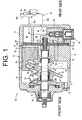
- FIG. 1 is a longitudinal cross-sectional view of a variable displacement compressor equipped with a control valve according to a first preferred embodiment of the present invention;
- FIG. 2 is a cross-sectional view of the control valve during maximum-displacement operation of the compressor according to the first preferred embodiment;
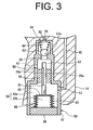
- FIG. 3 is a cross-sectional view of the control valve during stop of the compressor according to the first preferred embodiment;
- FIG. 4 is a cross-sectional view of the control valve during variable-displacement operation of the compressor according to the first preferred embodiment;
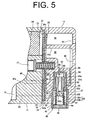
- FIG. 5 is a cross-sectional view of the control valve of a variable displacement compressor during its maximum-displacement operation according to a second preferred embodiment of the present invention;
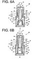
- FIG. 6A is a cross-sectional view of the control valve during the stop of the compressor according to the second preferred embodiment; and
- FIG. 6B is a cross-sectional view of the control valve during the variable-displacement operation of the compressor according to the second preferred embodiment.
- The following will describe a clutch type variable displacement compressor (hereinafter referred to merely as "compressor") according to a first preferred embodiment of the present invention with reference to FIGS. 1 through 4. Referring to FIG. 1, the
compressor 10 has ahousing 11 as an outer shell including acylinder block 12 defining therein a plurality ofcylinder bores 12a, afront housing 13 and arear housing 14. Thefront housing 13 is joined to the front end of thecylinder block 12 and therear housing 14 is joined to the rear end of thecylinder block 12. Thefront housing 13, thecylinder block 12 and therear housing 14 are integrally fixed to each other by a plurality of bolts 15 (only one being shown in FIG. 1) inserted through thefront housing 13, thecylinder block 12 and therear housing 14. - The
front housing 13 and thecylinder block 12 cooperate to define a control-pressure chamber (or a crank chamber) 16 through which adrive shaft 17 extends. Thedrive shaft 17 is rotatably supported by aradial bearing 18 provided at the front of thefront housing 13 and aradial bearing 19 provided at the center of thecylinder block 12. Ashaft seal mechanism 20 is provided on thedrive shaft 17 forward of the radial bearing 18 in slide contact with the outer circumferential surface of thedrive shaft 17. Theshaft seal mechanism 20 has a lip seal which functions to prevent a refrigerant in the control-pressure chamber 16 from leaking from between thefront housing 13 and thedrive shaft 17. - The
drive shaft 17 is connected at its front end to an external drive source (not shown) through a clutch mechanism (not shown). The clutch mechanism is engaged to transmit the drive force from the external drive source to thedrive shaft 17 or disengaged to shut off the transmission. Alug plate 21 is secured to thedrive shaft 17 in the control-pressure chamber 16 for rotation therewith. Aswash plate 23 of a displacement-changingmechanism 22 is provided behind thelug plate 21 and supported by thedrive shaft 17 so as to be slidable in the axial direction of thedrive shaft 17 and inclinable relative to the axis of thedrive shaft 17. Ahinge mechanism 24 is interposed between theswash plate 23 and thelug plate 21 so that theswash plate 23 and thelug plate 21 are connected therethrough. Thehinge mechanism 24 allows theswash plate 23 andlug plate 21 to rotate synchronously with and to be inclined relative to thedrive shaft 17. - A coil spring 25 is disposed on the
drive shaft 17 between thelug plate 21 and theswash plate 23. Atubular body 26 is slidably disposed on thedrive shaft 17 and urged rearward by the coil spring 25. Thetubular body 26 urges theswash plate 23 rearward or in the direction which causes the inclination angle of theswash plate 23 to be decreased. It is noted that the inclination angle of theswash plate 23 refer to an angle made between an imaginary plane perpendicular to the axis of thedrive shaft 17 and the flat surface of theswash plate 23. Theswash plate 23 has astopper 23a projecting from the front thereof for determining the maximum inclination of theswash plate 23 by contact with thelug plate 21 as shown in FIG.1. A retainingring 27 is fitted on thedrive shaft 17 in rear of theswash plate 23 and acoil spring 28 is disposed on thedrive shaft 17 between the retainingring 27 and theswash plate 23. The minimum inclination of theswash plate 23 is determined by the contact thereof with the front of thecoil spring 28. - A single-headed
piston 29 is reciprocatably disposed in each of the cylinder bores 12a of thecylinder block 12. Thepiston 29 is engaged at its neck with the outer periphery of theswash plate 23 through a pair ofshoes 30. When theswash plate 23 is driven to rotate by thedrive shaft 17, eachpiston 29 reciprocates through theshoes 30. As shown in FIG. 1, avalve plate 32, valve-formingplates retainer 35 are interposed between therear housing 14 and thecylinder block 12. Therear housing 14 defines therein at the center asuction chamber 38 which is in communication with acompression chamber 31 in each cylinder bore 12a through asuction port 36 formed in thevalve plate 32. Therear housing 14 defines therein at the radially outer region adischarge chamber 39. Thedischarge chamber 39 and thesuction chamber 38 are separated by apartition 14a formed in therear housing 14. - The
valve plate 32 and eachpiston 29 cooperate to define thecompression chamber 31 in therespective cylinder bore 12a. Thevalve plate 32 has thesuction port 36 which is in communication with thesuction chamber 38 and adischarge port 37 which is in communication with thedischarge chamber 39. The valve-formingplate 33 is a plate which forms a suction valve (not shown) interposed between eachcompression chamber 31 and thesuction chamber 38, while the valve-formingplate 34 is a plate which forms adischarge valve 34a or a reed valve interposed between eachdischarge port 37 and thedischarge chamber 39. Theretainer 35 functions to limit the maximum opening of thedischarge valve 34a. - As the
piston 29 moves from its top dead center toward its bottom dead center, the refrigerant in thesuction chamber 38 is drawn into thecompression chamber 31 through thesuction port 36 and the suction valve. As thepiston 29 moves from its bottom dead center toward its top dead center, the refrigerant drawn in thecompression chamber 31 is compressed to a predetermined pressure and discharged into thedischarge chamber 39 through thedischarge port 37 and thedischarge valve 34a. The inclination angle of theswash plate 23 is determined depending on the balance among the rotation moment developed by the centrifugal force of theswash plate 23, the moment of inertia caused by the inertial force of thepiston 29, the moment caused by the pressure of the refrigerant and the like. The moment caused by the pressure of the refrigerant is a moment which is determined by the relation between the pressure in thecompression chamber 31 and the pressure in the control-pressure chamber 16 acting on the back of thepiston 29 and this moment is applied in the direction which causes theswash plate 23 to be increased or decreased depending on the variation of the pressure in the control-pressure chamber 16. - The following will describe an external
refrigerant circuit 42 in which the above-describedcompressor 10 is connected. In this preferred embodiment, thecompressor 10 and the externalrefrigerant circuit 42 comprise a refrigerating circuit through which the refrigerant circulates. Thesuction chamber 38 is connected to the externalrefrigerant circuit 42 through aninlet 40 formed in therear housing 14. Thus, the refrigerant is supplied from the externalrefrigerant circuit 42 through theinlet 40 into thesuction chamber 38. In this preferred embodiment, thesuction chamber 38 and theinlet 40 comprise a suction-pressure region of thecompressor 10. Thedischarge chamber 39 is connected to the externalrefrigerant circuit 42 through anoutlet 41 formed in therear housing 14. Thus, the refrigerant in thedischarge chamber 39 is discharged out of thecompressor 10 into the externalrefrigerant circuit 42 through theoutlet 41. In this preferred embodiment, thedischarge chamber 39 and theoutlet 41 comprise a discharge-pressure region of thecompressor 10. As shown schematically in FIG. 1, the externalrefrigerant circuit 42 includes a heat exchanger orcondenser 43 for removing heat from the refrigerant, anexpansion valve 44 and a heat exchanger or anevaporator 45 for transferring the heat of the ambient air to the refrigerant. Theexpansion valve 44 is an automatic valve which is operable to sense the temperature of the refrigerant at the outlet of theevaporator 45 and to control the flow of the refrigerant according to the variation in the temperature. - The
compressor 10 has acontrol valve 50 which is operable to adjust the pressure in the control-pressure chamber 16 thereby to appropriately change the moment due to the pressure of the refrigerant, so that the inclination angle of theswash plate 23 is set between the minimum and the maximum inclination angles. - As shown in FIG. 1, the
control valve 50 is provided in therear housing 14 which supplies the refrigerant in the discharge-pressure region into the control-pressure chamber 16. As shown in FIG. 2, thecontrol valve 50 includes atubular valve housing 51 having therein a plurality of chambers, avalve body 63 operable to open and close a refrigerant-supply passage in thecontrol valve 50, a pressure-sensingmechanism 66 which operates according to the variation of the pressure in thesuction chamber 38, and areciprocatable rod 70 whose movement is controlled by the pressure-sensingmechanism 66. - As shown in FIG. 2, the
valve housing 51 defines therein a pressure-sensingchamber 52, acommunication chamber 53, and avalve chamber 54. The pressure-sensingchamber 52 is located at the lower end of thevalve housing 51, thevalve chamber 54 is located at the upper end of thevalve housing 51, and thecommunication chamber 53 is located between the pressure-sensingchamber 52 and thevalve chamber 54. Apartition member 55 is provided in thevalve housing 51 between the pressure-sensingchamber 52 and thecommunication chamber 53 and has ashaft hole 55a. The pressure-sensingchamber 52 and thecommunication chamber 53 are separated by thepartition member 55. Thevalve housing 51 has apartition 51 a which separates thecommunication chamber 53 and thevalve chamber 54. Thepartition 51 a has avalve hole 56. - The
valve housing 51 has athird port 57 which is in communication with the pressure-sensingchamber 52, asecond port 58 which is in communication with thecommunication chamber 53 and afirst port 59 which is in communication with thevalve chamber 54. As shown in FIG. 1, thethird port 57 is in communication with thesuction chamber 38 through apassage 60 formed in therear housing 14, thesecond port 58 is in communication with the control-pressure chamber 16 through apassage 61 formed in therear housing 14, theretainer 35, thevale forming plate 34, thevalve plate 32, the valve-formingplate 33 and thecylinder block 12, and thefirst port 59 is in communication with thedischarge chamber 39 through apassage 62 formed in therear housing 14. - The refrigerant-supply passage is provided in the
valve housing 51 passing through thevalve chamber 54, thevalve hole 56 and thecommunication chamber 53 thereby connecting thefirst port 59 to thesecond port 58. In other words, the refrigerant-supply passage includes thevalve chamber 54, thevalve hole 56 and thecommunication chamber 53. Aspherical valve body 63 and acoil spring 64 as an urging member are disposed in thevalve chamber 54. Thevalve body 63 has a diameter greater than that of thevalve hole 56 for closing thevalve hole 56. Thevalve body 63 is constantly urged by thecoil spring 64 in the direction that causes thevalve hole 56 to be closed. - The pressure-sensing
mechanism 66 is disposed in the pressure-sensingchamber 52. The pressure-sensingmechanism 66 includes a bellows 67 as a pressure-sensing member which divides the pressure-sensingchamber 52 into a variable-pressure chamber 52a and a constant-pressure chamber 52b. The bellows 67 is fixed at its fixed end to anend wall 69 which closes the lower end of thevalve housing 51. The constant-pressure chamber 52b inside thebellows 67 is hermitically closed and maintained at a predetermined constant pressure. The variable-pressure chamber 52a is located around the constant-pressure chamber 52b, and the pressure in the variable-pressure chamber 52a varies according to the variation of the pressure in thesuction chamber 38. Thus, when the pressure in the variable-pressure chamber 52a is lower than that in the constant-pressure chamber 52b, thebellows 67 expands. On the other hand, when the pressure in the variable-pressure chamber 52a is higher than that in the constant-pressure chamber 52b, thebellows 67 contracts. In other words, the pressure difference between the constant-pressure chamber 52b and the variable-pressure chamber 52a produces a force causing thebellows 67 to move, namely, expand or contract. - A
movable member 68 is fixed to the movable end of thebellows 67. Themovable member 68 is also fixed to the lower end of therod 70. Therod 70 has a diameter corresponding to that of theshaft hole 55a. The length of therod 70 is set such that when the bellows 67 expands to its maximum length, therod 70 moves thevalve body 63 away from thevalve hole 56 against the urging force of thecoil spring 64. Therod 70 has arecess 70a formed in the lateral surface thereof and extending in the axial direction thereof. Therecess 70a is formed in therod 70 such that when thebellows 67 contracts substantially to its minimum length the pressure-sensingchamber 52 and thecommunication chamber 53 are made in fluid communication through therecess 70a, as shown in FIG. 3. In other words, a liquid-discharge passage is provided in thevalve housing 51 passing through thecommunication chamber 53, therecess 70a and the pressure-sensingchamber 52 for connecting thesecond port 58 to thethird port 57, that is, the liquid-discharge passage includes thecommunication chamber 53, therecess 70a and the pressure-sensingchamber 52. The liquid-discharge passage is provided for discharging or removing the liquid refrigerant accumulated in the control-pressure chamber 16 into thesuction chamber 38 at the start-up of thecompressor 10. It is noted that the liquid-discharge passage may be provided merely by forming therecess 70a in the lateral surface of therod 70. Meanwhile, ableed passage 46 having a throttle is formed in thecylinder block 12, the valve-formingplate 33, thevalve plate 32, thevale forming plate 34 and theretainer 35, thus connecting the control-pressure chamber 16 to thesuction chamber 38, as shown in FIG. 1. Thebleed passage 46 is provided for releasing the pressure in the control-pressure chamber 16. - The following will describe the operation of the
control valve 50. In the case where thecompressor 10 remains at a stop for a long period of time, the pressure inside thecompressor 10 is equalized and the refrigerating circuit including thecompressor 10 is gradually cooled by the ambient air. Since thecompressor 10 is relatively easy to cool, the refrigerant in the refrigerating circuit tends to flow into thecompressor 10. More specifically, the refrigerant converts into liquid state if the refrigerating circuit is cooled so that the temperature thereof falls below the temperature of the saturated vapor pressure of the refrigerant, and the liquid refrigerant tends to be accumulated in thecompressor 10. In the case where thecompressor 10 remains at a stop for a long period of time, the equalized pressure in the refrigerating circuit is much higher than the pressure that is present in the suction-pressure region during the operation of thecompressor 10. In other words, the pressure in the variable-pressure chamber 52a is much higher than that constant-pressure chamber 52b in the in the pressure-sensingchamber 52. Thus, as shown in FIG. 3, thebellows 67 contracts to its minimum length thereby to provide the fluid communication between thecommunication chamber 53 and the pressure-sensingchamber 52 through therecess 70a of therod 70, and thevalve body 63 then closes thevalve hole 56. In this state, the refrigerant-supply passage is closed and the liquid-discharge passage is opened in thecontrol valve 50. - Subsequently, if cooling is required, the clutch mechanism is engaged to transmit the drive force from the external drive source to the
compressor 10 for starting thecompressor 10 which is then at a stop. At the beginning of the start-up, theswash plate 23 of thecompressor 10 is inclined at its minimum inclination angle, that is, thecompressor 10 operates at its minimum displacement. During this minimum-displacement operation of thecompressor 10 at the beginning of the start-up, each of thepistons 29 reciprocates in the respective cylinder bore 12a for its minimum distance of stroke. When the liquid-discharge passage is opened, the reciprocation of thepistons 29 causes the refrigerant to flow from the control-pressure chamber 16 through thesuction chamber 38 into thecompression chamber 31. Since the liquid-discharge passage is then opened, the liquid refrigerant in the control-pressure chamber 16 is fully discharged into thesuction chamber 38 flowing through thepassage 61, the control valve 50 (thesecond port 58, thecommunication chamber 53, therecess 70a, the variable-pressure chamber 52a and the third port 57) and thepassage 60 as thepistons 29 reciprocate in the cylinder bores 12a. - Since the liquid refrigerant in the control-
pressure chamber 16 is thus fully discharged into thesuction chamber 38, the pressure in the control-pressure chamber 16 can be lowered below the saturated vapor pressure of the refrigerant. As the pressure in the control-pressure chamber 16 is lowered, the inclination angle of theswash plate 23 is increased, thus increasing the displacement of thecompressor 10. With an increase in the displacement of thecompressor 10, the pressure in the variable-pressure chamber 52a in thecontrol valve 50 is lowered further and thebellows 67 expands, accordingly. For example, during the maximum displacement operation of thecompressor 10 when the cooling load is high, thebellows 67 expands to such a degree that therod 70 approaches close to but is yet to be in contact with thevalve body 63 as shown in FIG. 2. In this position of therod 70, the liquid-discharge passage is closed. In this case, the liquid-discharge passage in thecontrol valve 50 is closed by therod 70 and the pressure in the control-pressure chamber 16 is released through thebleed passage 46 for maintaining the maximum displacement operation of thecompressor 10. Incidentally, blow-by gas constantly flows from thecompression chamber 31 into the control-pressure chamber 16 through the clearance between thepiston 29 and thecylinder bore 12a, thereby increasing the pressure in the control-pressure chamber 16. - For improving the operating efficiency of the
compressor 10, the communication between thecommunication chamber 53 and the variable-pressure chamber 52a should preferably be closed at the moment when the liquid refrigerant in the control-pressure chamber 16 is just fully discharged. The pressure in thesuction chamber 38 is gradually lowered from the saturated vapor pressure level when the liquid refrigerant is discharged out of thecompressor 10 and the inclination angle of theswash plate 23 is increased. Therefore, it is preferable that the pressure which is slightly below the saturated vapor pressure should be set as a predetermined pressure at which thebellows 67 expands to move therod 70 so that the liquid-discharge passage is closed. However, since the saturated vapor pressure depends on temperature, the above predetermined pressure cannot be determined readily. In this preferred embodiment, if chlorofluorocarbon (HFC-134a) is used as the refrigerant, the predetermined pressure is set at 0.4 to 0.45 MPa on the basis of a saturated vapor pressure of 0.49 MPa at a temperature of 15°C. Since the suction pressure ranges from 0.2 to 0.4 MPa while thecompressor 10 is operating at its maximum or medium displacement, the liquid-discharge passage may be closed after the liquid refrigerant is fully discharged and the displacement of thecompressor 10 is increased. - When the cooling load is decreased, the
compressor 10 then operates such that its displacement is decreased from the maximum at the maximum displacement operation. More specifically, thecompressor 10 attempts to maintain its maximum-displacement operation in spite of the decreased cooling load, but the pressure in the suction-pressure region is lowered further due to the decreased cooling load. Accordingly, the pressure in the variable-pressure chamber 52a is lowered, so that thebellows 67 expands further than that at the maximum displacement operation of thecompressor 10 thereby to cause therod 70 to press thevalve body 63 against thecoil spring 64 and thevalve hole 56 to be opened, as shown in FIG. 4. - With the
valve hole 56 opened, a part of the high-pressure refrigerant in thedischarge chamber 39 is introduced into the control-pressure chamber 16 through thepassage 62, the control valve 50 (thefirst port 59, thevalve chamber 54, thevalve hole 56, thecommunication chamber 53 and the second port 58) and thepassage 61. Thus, the inclination angle of theswash plate 23 is decreased and thecompressor 10 performs its variable-displacement operation in response to the varying cooling load. During the variable-displacement operation of thecompressor 10, the liquid-discharge passage is kept closed. It is noted that opening and closing thevalve hole 56 by thevalve body 63 depend on the balance between the urging force of thecoil spring 64 and the urging force of therod 70 developed by the pressure-sensingmechanism 66. - According to the
control valve 50 of the above-described preferred embodiment, the following advantageous effects are achieved. - (1) The refrigerant in the control-
pressure chamber 16 is discharged at a start-up of thecompressor 10, so that the pressure in the control-pressure chamber 16 is lowered and theswash plate 23 is controlled such that the displacement of thecompressor 10 is increased. The liquid-discharge passage is closed when the refrigerant pressure in the suction-pressure region is lowered and reaches the aforementioned predetermined pressure as thecompressor 10 is started. Therefore, the liquid refrigerant accumulated in the control-pressure chamber 16 is fully discharged into the suction-pressure region after the start-up of thecompressor 10, thus permitting the pressure in the control-pressure chamber 16 to be lowered faster than in the conventional compressor. - (2) The pressure equalization inside the
compressor 10 is set by the saturated vapor pressure of the refrigerant with respect to the temperature of the ambient air. The position of therod 70 is controlled by maintaining the pressure equalization at the start-up of thecompressor 10 and canceling the pressure equalization afterward. According to the position of therecess 70a of therod 70, opening and closing the liquid-discharge passage is controlled. - (3) The wider liquid-discharge passage requires less time for fully discharging the liquid refrigerant from the control-
pressure chamber 16 into the suction-pressure region. Thus, return characteristics of thecompressor 10 is improved. However, if the liquid-discharge passage is opened to connect the control-pressure chamber 16 to the suction-pressure region after return of or the start-up of thecompressor 10, a lot of the refrigerant may flow from the control-pressure chamber 16 into the suction-pressure region. The flow of the refrigerant in thecompressor 10 is needed for lubricating the sliding elements in thecompressor 10 but it does not contribute to cooling by the refrigerant circulation in the refrigerating circuit. Thus, it deteriorates cooling performance. The cooling performance is prevented from being deteriorated by closing the liquid-discharge passage after the return of thecompressor 10. - The following will describe a
control valve 80 according to a second preferred embodiment of the present invention with reference to FIGS. 5 and 6. Major parts of the compressor of this preferred embodiment except thecontrol valve 80 are substantially the same as the counterparts of the first preferred embodiment. Thus, common or similar elements or parts are designated by the same reference numerals as those of the first preferred embodiment and, therefore, the description thereof is omitted. Referring to FIG. 5, thecontrol valve 80 includes avalve housing 81, arod 87 and a pressure-sensingmechanism 96. Thevalve housing 81 defines therein a pressure-sensingchamber 82 which is in communication with the control-pressure chamber 16, avalve chamber 83 which is in communication with thedischarge chamber 39 and acommunication chamber 84 which is in communication with thesuction chamber 38. The pressure-sensingchamber 82 is located at the lower end of thevalve housing 81, thecommunication chamber 84 is provided at the upper end of thevalve housing 81, and thevalve chamber 83 is located between the pressure-sensingchamber 82 and thecommunication chamber 84. Thevalve housing 81 has afirst partition 81a located between the pressure-sensingchamber 82 and thevalve chamber 83 and having avalve hole 85 and asecond partition 81 b located between thevalve chamber 83 and thecommunication chamber 84 and having ashaft hole 86. - The
rod 87 is reciprocatably slidably disposed in thevalve housing 81. Therod 87 has a large-diameter portion 87a located in thecommunication chamber 84 and thevalve chamber 83, a small-diameter portion 87b located in the pressure-sensingchamber 82 and a throughhole 88 extending axially through the center of therod 87. The large-diameter portion 87a has a diameter corresponding to that of theshaft hole 86, and the small-diameter portion 87b has a diameter smaller than that of thevalve hole 85. Therod 87 has anend surface 87c provided at the step between the small-diameter portion 87b and the large-diameter portion 87a. Theend surface 87c functions as a valve body which is contactable with thefirst partition 81a, thus providing and shutting off the fluid communication between the pressure-sensingchamber 82 and thevalve chamber 83. In this preferred embodiment, thevalve chamber 83, thevalve hole 85 and the pressure-sensingchamber 82 correspond to the refrigerant-supply passage of thecontrol valve 80, and theend surface 87c of therod 87 corresponds to a valve body for opening and closing the refrigerant-supply passage. The throughhole 88 of therod 87 provides fluid communication between the pressure-sensingchamber 82 and thecommunication chamber 84. Therod 87 is urged toward the pressure-sensingchamber 82 by acoil spring 89 disposed in thecommunication chamber 84. - The
communication chamber 84 is located at the upper end of the large-diameter portion 87a, and thevalve housing 81 has at its upper end athird port 90 which is in communication with thecommunication chamber 84. Thethird port 90 is also in communication with thesuction chamber 38 through apassage 93 formed in therear housing 14. Thevalve chamber 83 is formed around the large-diameter portion 87a, and thevalve housing 81 has afirst port 91 formed through its lateral wall which is in communication with thevalve chamber 83. Thefirst port 91 is also in communication with thedischarge chamber 39 through apassage 94 formed in therear housing 14. The pressure-sensingchamber 82 is located at the lower end of the small-diameter portion 87b, and thevalve housing 81 has at its lower end asecond port 92 which is in communication with a variable-pressure chamber 82a. Thesecond port 92 is also in communication with the control-pressure chamber 16 through apassage 95 formed in therear housing 14, the valve-formingplate 33, thevalve plate 32, the valve-formingplate 34 and theretainer 35. - The pressure-sensing
mechanism 96 is disposed in the pressure-sensingchamber 82. The pressure-sensingmechanism 96 has abellows 97 as a pressure-sensing member which divides the pressure-sensingchamber 82 into the variable-pressure chamber 82a and a constant-pressure chamber 82b. The bellows 97 is fixed at its fixed lower end to anend wall 98 which closes the lower end of thevalve housing 81. The constant-pressure chamber 82b inside thebellows 97 is hermitically closed and maintained at a predetermined constant pressure. The variable-pressure chamber 82a is located around the constant-pressure chamber 82b, and the pressure in the variable-pressure chamber 82a varies with the pressure in thesuction chamber 38. Thus, when the pressure in the variable-pressure chamber 82a is lower than that in the constant-pressure chamber 82b, thebellows 97 expands. On the other hand, when the pressure in the variable-pressure chamber 82a is higher than that in the constant-pressure chamber 82b, thebellows 97 contracts. In other words, the pressure difference between the constant-pressure chamber 82b and the variable-pressure chamber 82a creates a force which causes thebellows 97 to expand or contract. - A
movable member 99 is fixed to the movable upper end of thebellows 97, and anannular valve member 100 is fixed to themovable member 99 for selectively providing and shutting off the fluid communication between the pressure-sensingchamber 82 and the throughhole 88. Thevalve member 100 has a taperedsurface 100a which is tapered toward the bellows 97. The bellows 97 expands such that the small-diameter portion 87b of therod 87 comes into contact at the outer periphery of its end with the taperedsurface 100a, thereby shutting off the communication between thecommunication chamber 84 and the pressure-sensingchamber 82. When the bellows 97 contracts, on the other hand, thevalve member 100 moves away from the small-diameter portion 87b of therod 87, providing the communication between the pressure-sensingchamber 82 and thecommunication chamber 84 via the throughhole 88. In this preferred embodiment, the variable-pressure chamber 82a, the throughhole 88 and thecommunication chamber 84 correspond to the liquid-discharge passage of thecontrol valve 80. - The following will describe the operation of the
control valve 80 of this preferred embodiment. When thecompressor 10 remains at a stop for a long period of time, the liquid refrigerant is accumulated in thecompressor 10 and the pressure in the refrigerating circuit is substantially equalized. The equalized pressure in the refrigerating circuit is much higher than the pressure in the suction-pressure region of thecompressor 10 during its operation. In other words, the pressure in the variable-pressure chamber 82a is much higher than that in the constant-pressure chamber 82b of the pressure-sensingchamber 82. Thus, as shown in FIG. 6A, thebellows 97 contracts to its minimum length thereby to move thevalve member 100 away from therod 87, and therod 87 is urged by thecoil spring 89 such that theend surface 87c closes thevalve hole 85. In this state of thecontrol valve 80, the refrigerant-supply passage is closed and the liquid-discharge passage is opened. - Subsequently, if cooling is required, the clutch mechanism is engaged to transmit the drive force from the external drive source to the compressor for starting the compressor which is then at a stop. During the minimum-displacement operation of the compressor at the beginning of the start-up, each of the
pistons 29 reciprocates in itscylinder bore 12a for its minimum distance of stroke. When the liquid-discharge passage is opened, the reciprocation of thepistons 29 causes the refrigerant in the control-pressure chamber 16 to flow therefrom through thesuction chamber 38 into thecompression chamber 31. Since the liquid-discharge passage is then opened, the liquid refrigerant in the control-pressure chamber 16 is fully discharged by the reciprocation of thepistons 29 into thesuction chamber 38 through thepassage 95, the control valve 80 (thesecond port 92, the variable-pressure chamber 82a, the throughhole 88, thecommunication chamber 84 and the third port 90) and thepassage 93. - Since the liquid refrigerant in the control-
pressure chamber 16 is fully discharged into thesuction chamber 38, the pressure in the control-pressure chamber 16 can be lowered below the saturated vapor pressure of the refrigerant. As the pressure in the control-pressure chamber 16 is thus lowered, the inclination angle of theswash plate 23 is increased, thus increasing the displacement of the compressor. As the displacement of the compressor is increased, the pressure in the variable-pressure chamber 82a in thecontrol valve 80 is lowered further, so that thebellows 97 expands. For example, during the maximum-displacement operation of the compressor when the cooling load is high, thebellows 97 expands to such a degree that thevalve member 100 comes into contact with therod 87 as shown in FIG. 5. In this position of therod 87, the liquid-discharge passage is closed. - When the cooling load is decreased, the compressor then operates such that its displacement is decreased from the maximum at the maximum-displacement operation of the compressor. However, the compressor attempts to maintain its maximum displacement operation in spite of the reduced cooling load but the pressure in the suction-pressure region is lowered further due to the reduced cooling load. Accordingly the pressure in the variable-
pressure chamber 82a is lowered further. Thus, thebellows 97 expands further than at the maximum displacement operation of the compressor, causing thevalve member 100 to press therod 70 against thecoil spring 89 and thevalve hole 85 to be opened, as shown in FIG. 6B. - With the
valve hole 85 thus opened, a part of the high-pressure refrigerant in thedischarge chamber 39 is introduced into the control-pressure chamber 16 through thepassage 94, the control valve 80 (thefirst port 91, thevalve chamber 83, thevalve hole 85, the variable-pressure chamber 82a and the second port 92) and thepassage 95. Thus, the inclination angle of theswash plate 23 is decreased and the compressor performs its variable-displacement operation according to the cooling load. During the variable-displacement operation of the compressor, the liquid-discharge passage is kept closed. It is noted that opening and closing thevalve hole 85 by therod 87 depend on the balance between the urging force of thecoil spring 89 and the urging force of thevalve member 100 created by the pressure-sensingmechanism 96. - According to the
control valve 80 of this preferred embodiment, substantially the same advantageous effects as in the first preferred embodiment are achieved. Any liquid refrigerant accumulated in the control-pressure chamber 16 is fully discharged into the suction-pressure region during the start-up operation of thecompressor 10, thereby lowering the pressure in the control-pressure chamber 16 faster than in the conventional compressor. Although the pressure-sensingchamber 82 which is in communication with thesecond port 92 and thecommunication chamber 84 which is in communication with thethird port 90 are not located adjacent to each other in thecontrol valve 80, the throughhole 88 extending through therod 87 forms the liquid-discharge passage providing fluid communication between the above twochambers control valve 80 is improved. The diameter of the throughhole 88 is set relatively large so that the flow rate of the liquid refrigerant passing from the control-pressure chamber 16 through the throughhole 88 can be increased. Thus, the liquid refrigerant is immediately discharged fully from the control-pressure chamber 16 during the start-up operation of the compressor. Thecontrol valve 80 is more advantageous than thecontrol valve 50 of the first preferred embodiment in that the throughhole 88 allows a greater flow rate of the liquid refrigerant. - The present invention is not limited to the embodiments described above but may be modified into an alternative embodiment as exemplified below. In the first and second preferred embodiments, the liquid-discharge passage is closed during the maximum-displacement operation of the compressor. In the alternative embodiment, the liquid-discharge passage may be opened during the operation of the compressor other than the variable-displacement operation of the compressor.
- Therefore, the present examples and embodiments are to be considered as illustrative and not restrictive, and the invention is not to be limited to the details given herein but may be modified within the scope of the appended claims.
- A control valve for a clutch type variable displacement compressor includes a liquid-discharge passage for connecting a second port in communication with a control-pressure chamber of the compressor to a third port in communication with the suction-pressure region of the compressor. Opening and closing the liquid-discharge passage are controlled by movement of a pressure-sensing member of a pressure-sensing mechanism. The pressure-sensing member is placed such that the liquid-discharge passage is opened while pressure equalization inside the compressor at a stop of the compressor is maintained in starting the compressor from its stop state. The pressure-sensing member is moved in a direction which causes the liquid-discharge passage to be closed when a pressure in the suction-pressure region is lowered and reaches a predetermined pressure as the compressor is started.
Claims (11)
- A control valve for a clutch type variable displacement compressor having a control-pressure chamber, a discharge-pressure region and a suction-pressure region, the control valve including a first port in communication with the discharge-pressure region, a second port in communication with the control-pressure chamber, a third port in communication with the suction-pressure region, a refrigerant-supply passage for connecting the first port to the second port, a valve body operable to open and close the refrigerant-supply passage, a pressure-sensing mechanism operable to control the valve body according to a pressure in the suction-pressure region and including a pressure-sensing member, and a rod operable to move the valve body for opening and closing the refrigerant-supply passage, characterized in that the control valve includes a liquid-discharge passage for connecting the second port to the third port, in that opening and closing the liquid-discharge passage is controlled by movement of the pressure-sensing member, in that the pressure-sensing member is placed such that the liquid-discharge passage is opened while pressure equalization inside the compressor at a stop of the compressor is maintained in starting the compressor from its stop state, and in that the pressure-sensing member is moved in a direction which causes the liquid-discharge passage to be closed when a pressure in the suction-pressure region is lowered and reaches a predetermined pressure as the compressor is
- The control valve according to claim 1, wherein the liquid-discharge passage includes a recess formed in a lateral surface of the rod.
- The control valve according to claim 1, wherein the liquid-discharge passage includes a through hole extending through the rod.
- The control valve according to any one of claims 1 through 3, wherein the pressure-sensing member is a bellows expandable and contractible according to the pressure in the suction-pressure region.
- The control valve according to any one of claims 1 through 4, further comprising a valve housing that defines therein a valve chamber in communication with the first port, a communication chamber in communication with one of the second and third ports and a pressure-sensing chamber in communication with the other of the second and third ports.
- The control valve according to claim 5, wherein the pressure-sensing mechanism is disposed in the pressure-sensing chamber.
- The control valve according to any one of claims 5 and 6, wherein the valve body is disposed in the valve chamber.
- The control valve according to any one of claims 5 through 7, wherein the liquid-discharge passage includes the communication chamber and the pressure-sensing chamber.
- The control valve according to any one of claims 5 through 8, wherein the communication chamber is located between the valve chamber and the pressure-sensing chamber.
- The control valve according to any one of claims 5 through 8, wherein the valve chamber is located between the communication chamber and the pressure-sensing chamber.
- The control valve according to any one of claims 1 and 3, wherein the rod has a large-diameter portion and a small-diameter portion, the valve body being provided by a step formed between the large-diameter portion and the small-diameter portion.
Applications Claiming Priority (1)
| Application Number | Priority Date | Filing Date | Title |
|---|---|---|---|
| JP2005266147A JP2007077863A (en) | 2005-09-14 | 2005-09-14 | Control valve for clutch type variable displacement compressor |
Publications (2)
| Publication Number | Publication Date |
|---|---|
| EP1764505A1 true EP1764505A1 (en) | 2007-03-21 |
| EP1764505B1 EP1764505B1 (en) | 2008-05-28 |
Family
ID=37312034
Family Applications (1)
| Application Number | Title | Priority Date | Filing Date |
|---|---|---|---|
| EP06120172A Not-in-force EP1764505B1 (en) | 2005-09-14 | 2006-09-06 | Control valve for clutch type variable displacement compressor |
Country Status (4)
| Country | Link |
|---|---|
| US (1) | US20070059183A1 (en) |
| EP (1) | EP1764505B1 (en) |
| JP (1) | JP2007077863A (en) |
| DE (1) | DE602006001335D1 (en) |
Families Citing this family (4)
| Publication number | Priority date | Publication date | Assignee | Title |
|---|---|---|---|---|
| US20080226471A1 (en) * | 2007-03-12 | 2008-09-18 | Kabushiki Kaisha Toyota Jidoshokki | Variable displacement compressor |
| KR101607708B1 (en) * | 2009-09-30 | 2016-03-30 | 한온시스템 주식회사 | A control valve for Variable displacement swash plate type compressor |
| JP6136461B2 (en) * | 2013-03-29 | 2017-05-31 | 株式会社豊田自動織機 | Variable capacity compressor |
| JP6417757B2 (en) | 2013-09-19 | 2018-11-07 | 株式会社デンソー | In-vehicle optical sensor cleaning device |
Citations (3)
| Publication number | Priority date | Publication date | Assignee | Title |
|---|---|---|---|---|
| US6010312A (en) * | 1996-07-31 | 2000-01-04 | Kabushiki Kaisha Toyoda Jidoshokki Seiksakusho | Control valve unit with independently operable valve mechanisms for variable displacement compressor |
| EP1024286A2 (en) * | 1999-01-29 | 2000-08-02 | Kabushiki Kaisha Toyoda Jidoshokki Seisakusho | Control valve for variable displacement compressor |
| EP1081378A2 (en) * | 1999-08-31 | 2001-03-07 | Kabushiki Kaisha Toyoda Jidoshokki Seisakusho | Control valve for variable displacement compressor |
Family Cites Families (2)
| Publication number | Priority date | Publication date | Assignee | Title |
|---|---|---|---|---|
| US4428718A (en) * | 1982-02-25 | 1984-01-31 | General Motors Corporation | Variable displacement compressor control valve arrangement |
| JP4246975B2 (en) * | 2002-02-04 | 2009-04-02 | イーグル工業株式会社 | Capacity control valve |
-
2005
- 2005-09-14 JP JP2005266147A patent/JP2007077863A/en not_active Withdrawn
-
2006
- 2006-09-06 EP EP06120172A patent/EP1764505B1/en not_active Not-in-force
- 2006-09-06 DE DE602006001335T patent/DE602006001335D1/en not_active Expired - Fee Related
- 2006-09-13 US US11/520,970 patent/US20070059183A1/en not_active Abandoned
Patent Citations (3)
| Publication number | Priority date | Publication date | Assignee | Title |
|---|---|---|---|---|
| US6010312A (en) * | 1996-07-31 | 2000-01-04 | Kabushiki Kaisha Toyoda Jidoshokki Seiksakusho | Control valve unit with independently operable valve mechanisms for variable displacement compressor |
| EP1024286A2 (en) * | 1999-01-29 | 2000-08-02 | Kabushiki Kaisha Toyoda Jidoshokki Seisakusho | Control valve for variable displacement compressor |
| EP1081378A2 (en) * | 1999-08-31 | 2001-03-07 | Kabushiki Kaisha Toyoda Jidoshokki Seisakusho | Control valve for variable displacement compressor |
Also Published As
| Publication number | Publication date |
|---|---|
| EP1764505B1 (en) | 2008-05-28 |
| US20070059183A1 (en) | 2007-03-15 |
| DE602006001335D1 (en) | 2008-07-10 |
| JP2007077863A (en) | 2007-03-29 |
Similar Documents
| Publication | Publication Date | Title |
|---|---|---|
| EP1059443B1 (en) | Displacement control valve | |
| US7530797B2 (en) | Variable displacement compressor | |
| US6358017B1 (en) | Control valve for variable displacement compressor | |
| EP1918583B1 (en) | Suction throttle valve of a compressor | |
| EP2096308B1 (en) | Swash plate type variable displacement compressor | |
| US20090223244A1 (en) | Swash plate type compressor | |
| KR101541998B1 (en) | Variable displacement swash plate compressor | |
| KR101194431B1 (en) | Variable capacity compressor | |
| JP2003239857A (en) | Control device for variable displacement compressor | |
| EP1764505B1 (en) | Control valve for clutch type variable displacement compressor | |
| KR101788935B1 (en) | Variable displacement swash-plate compressor | |
| US10815980B2 (en) | Variable displacement swash plate type compressor | |
| JP2016169700A (en) | Variable displacement compressor | |
| US9915252B2 (en) | Variable displacement swash plate compressor having a fulcrum and an action point located on opposite sides of a drive shaft | |
| JPH0494470A (en) | Variable displacement swash plate type compressor | |
| US9903354B2 (en) | Variable displacement swash plate compressor | |
| KR101729831B1 (en) | Variable displacement swash plate compressor | |
| US11047373B2 (en) | Piston compressor including a suction throttle | |
| US9790936B2 (en) | Variable displacement swash plate compressor | |
| JP2017150315A (en) | Variable displacement swash plate compressor | |
| US20200309106A1 (en) | Variable displacement swash plate compressor | |
| US20170276126A1 (en) | Variable displacement type swash plate compressor | |
| JPH01232179A (en) | Variable displacement swash plate type compressor | |
| JPH0538366U (en) | Swash plate type compressor |
Legal Events
| Date | Code | Title | Description |
|---|---|---|---|
| PUAI | Public reference made under article 153(3) epc to a published international application that has entered the european phase |
Free format text: ORIGINAL CODE: 0009012 |
|
| 17P | Request for examination filed |
Effective date: 20060906 |
|
| AK | Designated contracting states |
Kind code of ref document: A1 Designated state(s): AT BE BG CH CY CZ DE DK EE ES FI FR GB GR HU IE IS IT LI LT LU LV MC NL PL PT RO SE SI SK TR |
|
| AX | Request for extension of the european patent |
Extension state: AL BA HR MK YU |
|
| AKX | Designation fees paid |
Designated state(s): DE FR IT |
|
| GRAP | Despatch of communication of intention to grant a patent |
Free format text: ORIGINAL CODE: EPIDOSNIGR1 |
|
| GRAS | Grant fee paid |
Free format text: ORIGINAL CODE: EPIDOSNIGR3 |
|
| GRAA | (expected) grant |
Free format text: ORIGINAL CODE: 0009210 |
|
| AK | Designated contracting states |
Kind code of ref document: B1 Designated state(s): DE FR IT |
|
| REF | Corresponds to: |
Ref document number: 602006001335 Country of ref document: DE Date of ref document: 20080710 Kind code of ref document: P |
|
| PGFP | Annual fee paid to national office [announced via postgrant information from national office to epo] |
Ref country code: FR Payment date: 20080917 Year of fee payment: 3 |
|
| PGFP | Annual fee paid to national office [announced via postgrant information from national office to epo] |
Ref country code: DE Payment date: 20080930 Year of fee payment: 3 |
|
| PLBE | No opposition filed within time limit |
Free format text: ORIGINAL CODE: 0009261 |
|
| STAA | Information on the status of an ep patent application or granted ep patent |
Free format text: STATUS: NO OPPOSITION FILED WITHIN TIME LIMIT |
|
| 26N | No opposition filed |
Effective date: 20090303 |
|
| PGFP | Annual fee paid to national office [announced via postgrant information from national office to epo] |
Ref country code: IT Payment date: 20090930 Year of fee payment: 4 |
|
| REG | Reference to a national code |
Ref country code: FR Ref legal event code: ST Effective date: 20100531 |
|
| PG25 | Lapsed in a contracting state [announced via postgrant information from national office to epo] |
Ref country code: DE Free format text: LAPSE BECAUSE OF NON-PAYMENT OF DUE FEES Effective date: 20100401 Ref country code: FR Free format text: LAPSE BECAUSE OF NON-PAYMENT OF DUE FEES Effective date: 20090930 |
|
| PG25 | Lapsed in a contracting state [announced via postgrant information from national office to epo] |
Ref country code: IT Free format text: LAPSE BECAUSE OF NON-PAYMENT OF DUE FEES Effective date: 20100906 |