EP1764484A2 - Turbine cooling air sealing with associated turbine engine and method for reengineering a gas turbine engine - Google Patents
Turbine cooling air sealing with associated turbine engine and method for reengineering a gas turbine engine Download PDFInfo
- Publication number
- EP1764484A2 EP1764484A2 EP06254738A EP06254738A EP1764484A2 EP 1764484 A2 EP1764484 A2 EP 1764484A2 EP 06254738 A EP06254738 A EP 06254738A EP 06254738 A EP06254738 A EP 06254738A EP 1764484 A2 EP1764484 A2 EP 1764484A2
- Authority
- EP
- European Patent Office
- Prior art keywords
- disk
- engine
- cover plate
- stage
- flow guide
- Prior art date
- Legal status (The legal status is an assumption and is not a legal conclusion. Google has not performed a legal analysis and makes no representation as to the accuracy of the status listed.)
- Granted
Links
Images


Classifications
-
- F—MECHANICAL ENGINEERING; LIGHTING; HEATING; WEAPONS; BLASTING
- F01—MACHINES OR ENGINES IN GENERAL; ENGINE PLANTS IN GENERAL; STEAM ENGINES
- F01D—NON-POSITIVE DISPLACEMENT MACHINES OR ENGINES, e.g. STEAM TURBINES
- F01D5/00—Blades; Blade-carrying members; Heating, heat-insulating, cooling or antivibration means on the blades or the members
- F01D5/02—Blade-carrying members, e.g. rotors
- F01D5/08—Heating, heat-insulating or cooling means
- F01D5/081—Cooling fluid being directed on the side of the rotor disc or at the roots of the blades
-
- F—MECHANICAL ENGINEERING; LIGHTING; HEATING; WEAPONS; BLASTING
- F01—MACHINES OR ENGINES IN GENERAL; ENGINE PLANTS IN GENERAL; STEAM ENGINES
- F01D—NON-POSITIVE DISPLACEMENT MACHINES OR ENGINES, e.g. STEAM TURBINES
- F01D11/00—Preventing or minimising internal leakage of working-fluid, e.g. between stages
- F01D11/001—Preventing or minimising internal leakage of working-fluid, e.g. between stages for sealing space between stator blade and rotor
-
- F—MECHANICAL ENGINEERING; LIGHTING; HEATING; WEAPONS; BLASTING
- F01—MACHINES OR ENGINES IN GENERAL; ENGINE PLANTS IN GENERAL; STEAM ENGINES
- F01D—NON-POSITIVE DISPLACEMENT MACHINES OR ENGINES, e.g. STEAM TURBINES
- F01D25/00—Component parts, details, or accessories, not provided for in, or of interest apart from, other groups
- F01D25/08—Cooling; Heating; Heat-insulation
- F01D25/12—Cooling
-
- F—MECHANICAL ENGINEERING; LIGHTING; HEATING; WEAPONS; BLASTING
- F02—COMBUSTION ENGINES; HOT-GAS OR COMBUSTION-PRODUCT ENGINE PLANTS
- F02C—GAS-TURBINE PLANTS; AIR INTAKES FOR JET-PROPULSION PLANTS; CONTROLLING FUEL SUPPLY IN AIR-BREATHING JET-PROPULSION PLANTS
- F02C7/00—Features, components parts, details or accessories, not provided for in, or of interest apart form groups F02C1/00 - F02C6/00; Air intakes for jet-propulsion plants
- F02C7/12—Cooling of plants
- F02C7/16—Cooling of plants characterised by cooling medium
- F02C7/18—Cooling of plants characterised by cooling medium the medium being gaseous, e.g. air
-
- F—MECHANICAL ENGINEERING; LIGHTING; HEATING; WEAPONS; BLASTING
- F02—COMBUSTION ENGINES; HOT-GAS OR COMBUSTION-PRODUCT ENGINE PLANTS
- F02C—GAS-TURBINE PLANTS; AIR INTAKES FOR JET-PROPULSION PLANTS; CONTROLLING FUEL SUPPLY IN AIR-BREATHING JET-PROPULSION PLANTS
- F02C7/00—Features, components parts, details or accessories, not provided for in, or of interest apart form groups F02C1/00 - F02C6/00; Air intakes for jet-propulsion plants
- F02C7/28—Arrangement of seals
Definitions
- the invention relates to gas turbine engines, and more specifically to a seal system for providing a fluid leakage restriction between components within such engines.
- Gas turbine engines operate by burning a combustible fuel-air mixture in a combustor and converting the energy of combustion into a propulsive force.
- Combustion gases are directed axially rearward from the combustor through an annular duct, interacting with a plurality of turbine blade stages disposed within the duct.
- the blades transfer the combustion gas energy to one or more disks, rotationally disposed about a central, longitudinal axis of the engine.
- Air for cooling the first-stage blades bypasses the combustor and is directed to an inner diameter cavity located between a first-stage vane frame and a first-stage rotor assembly. The rotational force of the rotor assembly pumps the cooling air radially outward and into a series of conduits within each blade, thus providing the required cooling.
- the outboard radius of the inner cavity is adjacent to the annular duct carrying the combustion gases, it must be sealed to prevent leakage of the pressurized cooling air.
- This area of the inner cavity is particularly challenging to seal, due to the differences in thermal and centrifugal growth between the stationary first-stage vane frame and the rotating first stage rotor assembly. In the past, designers have attempted to seal the outboard radius of inner cavities with varying degrees of success.
- a multi-step labyrinth seal separates the inner cavity into two regions of approximately equal size, an inner region and an outer region. Cooling air in the inner region is pumped between the rotating disk and labyrinth seal into the hollow conduits of the blades while the outer region is fluidly coupled to the annular duct carrying the combustion gases.
- a labyrinth seal's lands are typically pre-grooved to prevent interference between the knife-edge teeth and the lands during a maximum radial excursion of the rotor.
- the leakage restriction capability is reduced during low to intermediate radial excursions of the rotor assembly.
- Any cooling air that leaks by the labyrinth seal is pumped through the outer region and into the annular duct by the rotating disk. This pumping action increases the temperature of the disk in the area of the blades and creates parasitic drag, which reduces overall turbine efficiency.
- the rotating knife-edges also add additional rotational mass to the gas turbine engine, which further reduces engine efficiency.
- a brush seal separates the inner cavity into two regions, an inner region and a smaller, outer region.
- a freestanding sideplate assembly defines a disk cavity, which is in fluid communication with the inner region. Cooling air in the inner region enters the disk cavity and is pumped between the rotating sideplate and disk to the hollow conduits of the blades.
- the seal's bristle-to-land contact pressure increases during the maximum radial excursions of the rotor and may cause the bristles to deflect and set over time, reducing the leakage restriction capability during low to intermediate rotor excursions.
- Any cooling air that leaks by the brush seal is pumped into the outer region by the rotating disk. This pumping action increases the temperature of the disk in the area of the blades and creates parasitic drag, which reduces overall turbine efficiency.
- the freestanding sideplate and minidisk also adds rotational mass to the gas turbine engine, which further reduces engine efficiency.
- One aspect of the invention involves a turbine engine section having a stationary vane stage and a rotating blade stage.
- the blade stage is spaced from the vane stage to form an annular chamber therebetween.
- a manifold delivers a pressurized fluid to the chamber.
- An outer diameter (OD) sealing means restricts leakage of the pressurized fluid from the chamber.
- An inner diameter (ID) sealing means restricts leakage of the pressurized fluid from the chamber.
- a baffle or flow guide extends radially between the inner diameter sealing means and the manifold. The flow guide bisects the chamber to form a stationary chamber portion and a rotating chamber portion, the rotating chamber portion at least partially along a disk of the first blade stage.
- the OD sealing means may comprise a cover plate attached to the disk.
- the flow guide may be affixed to at least one of the manifold or ID seal with a bolted joint.
- the stationary chamber portion may be bounded by the manifold, the flow guide, and a seal land of the ID seal.
- the manifold may be affixed to the vane stage.
- the rotating chamber portion may be at least partially along a web of the disk.
- Another aspect of the invention involves a gas turbine engine with a cover plate mounted to an upstream side of a first disk of a turbine rotor stack.
- a cooling air outlet is positioned to direct cooling air to a region adjacent the first disk.
- the first disk has a perimeter array of slots. Blades in a first blade stage each have an inboard attachment portion received in an associated slot.
- the cover plate has a first portion engaging the first disk to retain the cover plate against movement away from the first disk.
- the cover plate has a second portion, outboard of the first portion and engaging the blades of the first blade stage to resist upstream movement of the blades.
- the cover plate has a sealing portion for engaging a sealing element inboard of a first stator vane stage.
- a flow guide extends between the cooling air outlet and an inboard seal with the rotor.
- the cover plate may have a radial span between an inner radius and perimeter radius.
- a ratio of the radial span to a hub radius at the first blade stage may be no more than 0.25, more narrowly 0.20.
- the cooling air outlet may have a characteristic radius from central longitudinal axis of the rotor.
- a ratio of the characteristic radius to a hub radius at the first blade stage may be no less than 0.60, more narrowly 0.70.
- the engagement may be via a locking ring.
- the cooling outlet may be a tangential on-board injector.
- Another aspect of the invention involves a gas turbine engine having a sealing system between first and second disks of a turbine rotor stack.
- the system includes a non-rotating first body secured inboard of a platform structure of an intermediate stage of stator vanes.
- the first body carries at least one abradable land.
- the first disk carries at least one first runner sealingly engaging the at least one land.
- the second disk carries at least one second runner sealingly engaging the at least one land.
- the first disk may be an upstream-most disk. There may be a plurality of such first runners on a first cover plate and a plurality of such second runners on a second cover plate.
- the sealing system may transmit substantially no longitudinal force and torque between the first and second disks.
- the sealing system may be bore-less.
- a gas turbine engine may be reengineered from a baseline configuration to a reengineered configuration.
- the reengineering may decrease a radial span of a cover plate while removing an inboard sealing portion of the cover plate and shifting a cooling air outlet outboard.
- the reengineering may further include adding a flow guide along a path of an air stream from the outlet.
- the major sections of a typical gas turbine engine 10 of FIG. 1 include in series, from front to rear and disposed about a central longitudinal axis 11, a low-pressure compressor 12, a high-pressure compressor 14, a combustor 16, a high-pressure turbine module 18 and a low-pressure turbine module 20.
- a working fluid 22 is directed generally downstream/rearward through the compressors 12, 14 and into the combustor 16, where fuel is injected and the mixture is burned.
- Hot combustion gases 24 exit the combustor 16 and expand within a core flowpath in an annular duct 30 through the turbines 18, 20 and exit the engine 10 as a propulsive thrust.
- a portion of the working fluid 22 exiting the high-pressure compressor 14, bypasses the combustor 16 and is directed to the high-pressure turbine module 18 for use as cooling air 40.
- FIG. 2 shows further details of the interface between the downstream end of the combustor 16 and the upstream end of the high pressure turbine module 18.
- the turbine module 18 includes a rotor assembly 52 including a stack of disks. An upstreammost first disk 54 is followed by a second disk 56. Additional disks (not shown) may follow.
- the exemplary disks extend from an inboard bore 58 to an outboard periphery 60 (FIG. 3).
- a web 62 extends between the bore 58 and the periphery 60.
- Extending radially inward from the periphery 60 are slots 66 forming a circumferential array.
- the slots 66 extend longitudinally, or near longitudinally, between faces 68 and 70 (FIG.
- FIG. 4 shows first stage blades 74 mounted to the first disk 54 and second stage blades 76 mounted to the second disk 56.
- the blades 74, 76 have airfoils 78 extending from roots 80 at platforms 82 to tips 84 (FIG. 2) in close facing proximity to outer air seal shrouds 86 carried by the case 50.
- the roots 72 (FIG. 4) depend from the platforms 82.
- inboard ends 88 of the roots 72 are spaced radially outward from inboard ends 90 of the slots 66 so as to create associated passageways 92.
- FIG. 2 shows a first stage of vanes 100 between the combustor 16 and the first stage of blades 74.
- a second stage of vanes 102 is shown between the first stage of blades 74 and the second stage of blades 76.
- the exemplary vanes 100, 102 have airfoils 104 extending between inboard platforms 106 and outboard shrouds 108.
- the exemplary shrouds 108 may be mounted to the case 50.
- Each stage of vanes may be formed as a continuous one-piece ring or may be formed as a segmented ring.
- FIG. 2 shows further details of a tangential on-board injection (TOBI) cooling system 120 directing a portion 122 of the air 40 for turbine cooling.
- the air stream 122 is directed from a diffuser plenum 124 inboard of the combustor 16.
- the system 120 includes a manifold 126 having a circumferential array of conduits 128 ending in outlets 130. Exiting the outlets 130, the air stream 122 (FIG. 4) may split into portions 132 and 133 extending generally radially outward and inward, respectively. The air stream 132 promptly splits into streams 134 and 135.
- TOBI tangential on-board injection
- the air stream 133 (FIG. 2) is directed into a chamber 140 between a forward/upstream face 142 of the web of the first stage disk on the one hand and the aft/downstream face 144 of a flow guide baffle 146 on the other hand.
- the flow guide baffle generally closes-off (but does not necessarily seal-off) a chamber 147 thereahead and inboard of the manifold 126.
- the chambers 140 and 147 may thus be regarded as portions of a larger chamber bisected by the flow guide baffle 146.
- the chamber 147 is a stationary chamber in that the surfaces bounding it are essentially non-rotoating.
- the chamber 140 is a partially rotating chamber in that a nontrivial portion of the surfaces bounding it rotate with (e.g., are part of) the rotor.
- the exemplary flow guide baffle 146 has an outboard portion mounted to the manifold 128 at a junction 148 (e.g., a bolt circle or slip joint).
- An inboard portion of the baffle 146 (isolated in FIG. 5) is mounted to a seal carrier 150 at a junction 152 (e.g., a bolt circle or slip joint).
- a forward portion of the exemplary seal carrier 150 is mounted to the manifold 126 at a junction 154 (e.g., a bolt circle).
- the seal carrier 150 carries a land 156 of an abradable seal material (e.g., honeycomb or slip joint).
- the land 156 is engaged by one or more (e.g., two shown) knife-edge members or runners 158 on an inboard first air seal member 160 mounted to the first stage disk 54.
- the land(s) 156 and runners 158 thus form a sealing system 162.
- the stream 133 counters any leakage from a rotor cooling stream 164 directing compressor air from a plenum 166 ahead of the seal carrier 150 and the inboard first air seal member 160.
- the stream 133 may also cool the disk 54 along the surface 142.
- the baffle reduces the volume of the pressurized air scrubbing against the rotating disk and serves to guide adjacent air stream and avoid or limit creating regions of turbulence and vorticity. This encourages laminar flow and associated high heat transfer and limits lossed due to disk windage.
- the baffle shape closely corresponds to the shape of the structure (e.g., the forward surface of the disk 54) on the opposite side of the chamber 140.
- FIG. 4 shows further details of the air streams 134 and 135. Both streams interact with a cover or face plate seal member 180 (hereafter "cover plate”).
- cover plate cover or face plate seal member 180
- the cover plate 180 extends from an inboard extremity 182 at a central opening to an outboard periphery 184.
- An inboard body portion 186 of the cover plate 180 serves to mount the cover plate 180 to the first stage disk 54.
- the mounting portion 186 extends radially outward from an inboard portion 188.
- the inboard portion 188 cooperates with an outwardly facing hook channel 190 on the forward/upstream face 142 of the first stage disk web.
- the cooperation is via a locking ring 192.
- the cooperation restrains forward/upstream movement of the cover plate 180 relative to the first stage disk.
- a retention portion 200 of the cover plate 180 branches off from the outboard end of the body portion 186 and extends to the periphery 184.
- the exemplary cover plate 180 is normally under stress to provide sufficient retention bias. Accordingly, the portion 200 is arcuate in section to best accommodate the stress and associated strain.
- a sealing portion 210 also branches off forward of the portion 200 and extends to one or more runners 212.
- the runner 212 sealingly engages an abradable seal material land 214 carried by a first outboard under platform air seal member 216 mounted to the platform of the first vane stage.
- the seal member 216 also includes an abradable seal material land 218 engaging runners 220 and 222 of the combined blade platforms and the first stage disk (e.g., as also shown in Ser. No. 11/146,798).
- the air stream 134 faces the combined sealing effects of the runners 212, 220, and 222 before passing between the platforms of the first vane and blade stages to enter the core flowpath 230.
- the stream 135 passes radially outward through apertures 232 (FIG. 6) in the cover plate 180.
- the apertures 232 may also serve to register the cover plate with anti-rotation lugs of the associated disk.
- the stream 135 passes between the cover plate portion 200 and the disk and enters the passageways 92. From the passageways 92, the stream 135 proceeds radially outward through a cooling passageway network 234 in each of the blades, ultimately exiting through fine cooling passageways (not shown) along the blade airfoil.
- FIG. 4 shows the cover plate 180 as having an inboard radius R I and an outboard radius R O relative to the engine axis 11 which forms a rotational axis of the rotor.
- a radial span of the cover plate 180 is the difference between R O and R I .
- FIG. 4 further shows a first stage hub radius R HI which is a peak radius of the first stage blade platforms 82.
- FIG. 4 further shows a characteristic radius R A of the cooling air outlets 130. This radius may be at a nominal radial center of the outlets, at a flow-average radius, or the like.
- An exemplary ratio of the cover plate radial span to R HI is about 0.185.
- An exemplary range for this ratio is up to 0.25, more narrowly up to 0.20.
- An exemplary ratio of R A to R HI is approximately 0.73.
- An exemplary range for this ratio is at least 0.70, more broadly at least 0.60.
- FIG. 7 shows corresponding portions of an exemplary baseline prior art engine.
- the prior art cooling air outlets 500 are relatively inboard.
- the prior art cover plate 502 has a relatively large radial span with the presence of an inboard portion 504 carrying runners 506 for interacting with land(s) 508 just outboard of the TOBI conduits.
- the TOBI outlet stream is split into portions 510, 512, and 514, respectively generally analogous to the streams 133, 134, and 135.
- the stream 512 passes around the runners 506 and into a chamber 520 before ultimately passing to the core flowpath.
- the stream 514 passes between the cover plate portion 504 and the disk web before ultimately reaching the blades.
- the stream 514 is heated as it passes between the cover plate portion 504 and disk web. This heating may be due to a combination of factors including heat transfer from the web and a centrifugal pumping effect. This reduces the blade cooling efficiency of the stream 514 requiring a greater flow rate to achieve a given blade cooling effect. Similar heating may occur to the stream 512. Additionally, generation of vorticity 522 in the cavity 520 may increase local heating of the surrounding hardware. High cooling air flow rates may compromise performance (e.g., power, efficiency, and/or emissions).
- the baffle 146 tends to close off the volume 147 (FIG. 2) thereahead and minimize the vortex heat pumping effect on the stream 133.
- the outward shift of the TOBI outlet minimizes heating of the stream 135. This allows cooler air to enter the blades.
- the sealing provided by the runners 212, 218, and 222 helps limit the flow rate of the stream 134 to help maintain proper engine performance.
- the reduced cover plate span is associated with reduced cover plate mass. Because this mass must be carried by the first disk, the mass reduction permits a reduction in the size (and therefore required mass) of the first disk. This may further increase engine performance, decrease engine mass, and the like.
- FIG. 4 also shows details of an exemplary interstage sealing system 248 associated with the second vane stage.
- a non-rotating seal body 250 is secured inboard of the second vane stage platforms 106 by a junction 252 (e.g., a bolt circle).
- the body 250 may be a continuous or segmented annulus.
- the body carries an upstream abradable sealing land 254 and downstream abradable sealing lands 256, 258, 260, 262, and 264.
- the land 254 is positioned to sealingly engage runners 266 and 268 of a downstream cover plate 270 mounted to the downstream side of the first stage disk 54.
- the lands 256, 258, and 260 are positioned to engage runners 280, 282, and 284 of a cover plate 286 mounted to the forward/upstream side of the second stage disk 56.
- the lands 262 and 264 are positioned to engage runners 288 and 290 of the combined second stage disk and second stage blade sealing members (e.g., on or adjacent blade platforms).
- the cover plate 270 may be of similarly small radial span (if not smaller) to the cover plate 180.
- An exemplary ratio of the cover plate radial span to the first stage hub radius is 0.143 for the cover plate 270.
- An exemplary range for this ratio is up to 0.25, more narrowly up to 0.20, and yet more narrowly up to 0.16.
- FIG. 7 shows a prior art interstage seal system 300 having a first body 302 from which a number of runners 304 extend.
- the first body structurally couples and rotates with the first and second stage disks.
- the runners 304 engage a land 306 carried by a non-rotating second body 308 mounted to the associated vane platforms.
- the first body 302 has a portion 310 spanning between peripheral portions of the adjacent disks and carrying the runners 304.
- the second body 302 has a bore 312 coupled by a web 314 to the portion 310.
- the sealing system 248 of FIG. 4 may have one or more of several advantages.
- the system 248 substantially does not structurally couple the disks 54 and 56 (e.g., the forces and torques transmitted are only the minor forces and torques transmitted by runner-to-land interaction). This decoupling permits greater independence of mechanically-induced and thermally-induced movements or shape changes between the disks.
- the rotating mass and its inertia may also be reduced. For example, the mass and inertia of the rotating cover plates 270 and 286 may be less than that of the first body 302 reducing the dead load pull.
- FIG. 8 shows an alternate implementation wherein the FIG. 4 forward/upstream cover plates on the first and second disks are eliminated.
- TOBI outlets 350 discharge cooling air streams 352, 354, and 356, respectively generally analogous to the streams 133, 134, and 135.
- the stream 352 passes between a baffle 358 and the first stage disk web to encounter a brush seal system 360.
- the stream 354 passes radially outward and encounters a hammerhead-type sealing system 362 (e.g., as is also disclosed in Ser. No. 11/146,801).
- the air stream 356 passes directly into the blade feed passageways 364.
- an interstage sealing system 380 has a non-rotating first body 382 secured inboard of and to the second stage vane platforms 384.
- lands 386 and 388 respectively seal with runners 390 and 392 of a cover plate 394 mounted to the first disk in similar fashion to that of FIG. 4. Sealing with the second disk is via a hammerhead-type sealing system 396.
- inboard and outboard lands are spaced apart and facing each other to define a channel accommodating a runner pair of the adjacent disk and blade root combination.
- FIG. 9 shows yet another alternate implementation wherein the FIG. 4 blade root seals are eliminated.
- the cover plate seals are maintained.
- the blade root seals are replaced by baffles 400 and 402, respectively isolating annular under-platform compartments in the associated seal bodies 408 and 410.
- the baffles 400 and 402 may have a generally forwardly-open C-shaped cross-section and may be formed of sheet metal.
- the baffles may be secured by fasteners, rivets, or by a slip fit.
- the baffles may be substantially non-structural (e.g., adding essentially no strength to the associated static hardware but merely serving to influence adjacent air flow).
Landscapes
- Engineering & Computer Science (AREA)
- Mechanical Engineering (AREA)
- General Engineering & Computer Science (AREA)
- Chemical & Material Sciences (AREA)
- Combustion & Propulsion (AREA)
- Turbine Rotor Nozzle Sealing (AREA)
- Sealing Using Fluids, Sealing Without Contact, And Removal Of Oil (AREA)
Abstract
Description
- The invention relates to gas turbine engines, and more specifically to a seal system for providing a fluid leakage restriction between components within such engines.
- Gas turbine engines operate by burning a combustible fuel-air mixture in a combustor and converting the energy of combustion into a propulsive force. Combustion gases are directed axially rearward from the combustor through an annular duct, interacting with a plurality of turbine blade stages disposed within the duct. The blades transfer the combustion gas energy to one or more disks, rotationally disposed about a central, longitudinal axis of the engine. In a typical turbine section, there are multiple, alternating stages of stationary vanes and rotating blades disposed in the annular duct.
- Because the combustion gas temperature may reach 2000°F (1093°C) or more, some blade and vane stages are cooled with lower temperature cooling air for improved durability. Air for cooling the first-stage blades bypasses the combustor and is directed to an inner diameter cavity located between a first-stage vane frame and a first-stage rotor assembly. The rotational force of the rotor assembly pumps the cooling air radially outward and into a series of conduits within each blade, thus providing the required cooling.
- Because the outboard radius of the inner cavity is adjacent to the annular duct carrying the combustion gases, it must be sealed to prevent leakage of the pressurized cooling air. This area of the inner cavity is particularly challenging to seal, due to the differences in thermal and centrifugal growth between the stationary first-stage vane frame and the rotating first stage rotor assembly. In the past, designers have attempted to seal the outboard radius of inner cavities with varying degrees of success.
- An example of such a seal is disclosed in
U.S. Pat. No. 4,701,105 , issued to Cantor and Farrand and entitled "Anti-Rotation Feature for a Turbine Rotor Faceplate". In this example, a multi-step labyrinth seal separates the inner cavity into two regions of approximately equal size, an inner region and an outer region. Cooling air in the inner region is pumped between the rotating disk and labyrinth seal into the hollow conduits of the blades while the outer region is fluidly coupled to the annular duct carrying the combustion gases. A labyrinth seal's lands are typically pre-grooved to prevent interference between the knife-edge teeth and the lands during a maximum radial excursion of the rotor. By designing the labyrinth seal for the maximum radial excursion of the rotor assembly, the leakage restriction capability is reduced during low to intermediate radial excursions of the rotor assembly. Any cooling air that leaks by the labyrinth seal is pumped through the outer region and into the annular duct by the rotating disk. This pumping action increases the temperature of the disk in the area of the blades and creates parasitic drag, which reduces overall turbine efficiency. The rotating knife-edges also add additional rotational mass to the gas turbine engine, which further reduces engine efficiency. - Another example of such a seal is disclosed in
U.S. Pat. No. 5,310,319 , issued to Grant and Hoyt and entitled "Free Standing Turbine Disk Sideplate Assembly" andU.S. Pat. No. 5,522,698 , issued to Butler and Gernhardt and entitled "Brush Seal Support and Vane Assembly Windage Cover". As this example illustrates, a brush seal separates the inner cavity into two regions, an inner region and a smaller, outer region. A freestanding sideplate assembly defines a disk cavity, which is in fluid communication with the inner region. Cooling air in the inner region enters the disk cavity and is pumped between the rotating sideplate and disk to the hollow conduits of the blades. The seal's bristle-to-land contact pressure increases during the maximum radial excursions of the rotor and may cause the bristles to deflect and set over time, reducing the leakage restriction capability during low to intermediate rotor excursions. Any cooling air that leaks by the brush seal is pumped into the outer region by the rotating disk. This pumping action increases the temperature of the disk in the area of the blades and creates parasitic drag, which reduces overall turbine efficiency. The freestanding sideplate and minidisk also adds rotational mass to the gas turbine engine, which further reduces engine efficiency. - One aspect of the invention involves a turbine engine section having a stationary vane stage and a rotating blade stage. The blade stage is spaced from the vane stage to form an annular chamber therebetween. A manifold delivers a pressurized fluid to the chamber. An outer diameter (OD) sealing means restricts leakage of the pressurized fluid from the chamber. An inner diameter (ID) sealing means restricts leakage of the pressurized fluid from the chamber. A baffle or flow guide extends radially between the inner diameter sealing means and the manifold. The flow guide bisects the chamber to form a stationary chamber portion and a rotating chamber portion, the rotating chamber portion at least partially along a disk of the first blade stage.
- In various implementations, the OD sealing means may comprise a cover plate attached to the disk. The flow guide may be affixed to at least one of the manifold or ID seal with a bolted joint. The stationary chamber portion may be bounded by the manifold, the flow guide, and a seal land of the ID seal. The manifold may be affixed to the vane stage. The rotating chamber portion may be at least partially along a web of the disk.
- Another aspect of the invention involves a gas turbine engine with a cover plate mounted to an upstream side of a first disk of a turbine rotor stack. A cooling air outlet is positioned to direct cooling air to a region adjacent the first disk. The first disk has a perimeter array of slots. Blades in a first blade stage each have an inboard attachment portion received in an associated slot. The cover plate has a first portion engaging the first disk to retain the cover plate against movement away from the first disk. The cover plate has a second portion, outboard of the first portion and engaging the blades of the first blade stage to resist upstream movement of the blades. The cover plate has a sealing portion for engaging a sealing element inboard of a first stator vane stage. A flow guide extends between the cooling air outlet and an inboard seal with the rotor.
- In various implementations, the cover plate may have a radial span between an inner radius and perimeter radius. A ratio of the radial span to a hub radius at the first blade stage may be no more than 0.25, more narrowly 0.20. The cooling air outlet may have a characteristic radius from central longitudinal axis of the rotor. A ratio of the characteristic radius to a hub radius at the first blade stage may be no less than 0.60, more narrowly 0.70. The engagement may be via a locking ring. The cooling outlet may be a tangential on-board injector.
- Another aspect of the invention involves a gas turbine engine having a sealing system between first and second disks of a turbine rotor stack. The system includes a non-rotating first body secured inboard of a platform structure of an intermediate stage of stator vanes. The first body carries at least one abradable land. The first disk carries at least one first runner sealingly engaging the at least one land. The second disk carries at least one second runner sealingly engaging the at least one land.
- In various implementations, the first disk may be an upstream-most disk. There may be a plurality of such first runners on a first cover plate and a plurality of such second runners on a second cover plate. The sealing system may transmit substantially no longitudinal force and torque between the first and second disks. The sealing system may be bore-less.
- Other aspects of the invention include methods of reengineering. For example, a gas turbine engine may be reengineered from a baseline configuration to a reengineered configuration. The reengineering may decrease a radial span of a cover plate while removing an inboard sealing portion of the cover plate and shifting a cooling air outlet outboard. The reengineering may further include adding a flow guide along a path of an air stream from the outlet.
- The details of one or more embodiments of the invention are set forth in the accompanying drawings and the description below. Other features and advantages of the invention will be apparent from the description and drawings, and from the claims.
-
- FIG. 1 is a simplified schematic sectional view of a gas turbine engine along a central, longitudinal axis.
- FIG. 2 is a partial longitudinal sectional view of turbine cooling system components of the engine of FIG. 1.
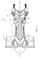
- FIG. 3 is a cutaway view of a first stage disk with turbine blades exploded off for illustration.
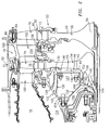
- FIG. 4 is an enlarged view of the system of FIG. 2.
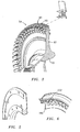
- FIG. 5 is a cutaway view of a flow guide baffle of the system of FIG. 2.
- FIG. 6 is a cutaway view of a cover plate of the system of FIG. 2.
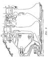
- FIG. 7 is a view of a prior art cooling system.
- FIG. 8 is a partial longitudinal sectional view of an alternate turbine cooling system.
- FIG. 9 is a partial longitudinal sectional view of a second alternate turbine cooling system.
- Like reference numbers and designations in the various drawings indicate like elements.
- The major sections of a typical
gas turbine engine 10 of FIG. 1 include in series, from front to rear and disposed about a centrallongitudinal axis 11, a low-pressure compressor 12, a high-pressure compressor 14, acombustor 16, a high-pressure turbine module 18 and a low-pressure turbine module 20. A workingfluid 22 is directed generally downstream/rearward through thecompressors combustor 16, where fuel is injected and the mixture is burned.Hot combustion gases 24 exit thecombustor 16 and expand within a core flowpath in anannular duct 30 through theturbines engine 10 as a propulsive thrust. A portion of the workingfluid 22 exiting the high-pressure compressor 14, bypasses thecombustor 16 and is directed to the high-pressure turbine module 18 for use as coolingair 40. - FIG. 2 shows further details of the interface between the downstream end of the
combustor 16 and the upstream end of the highpressure turbine module 18. Within theengine case 50, theturbine module 18 includes arotor assembly 52 including a stack of disks. An upstreammostfirst disk 54 is followed by asecond disk 56. Additional disks (not shown) may follow. The exemplary disks extend from an inboard bore 58 to an outboard periphery 60 (FIG. 3). Aweb 62 extends between thebore 58 and theperiphery 60. Extending radially inward from theperiphery 60 areslots 66 forming a circumferential array. Theslots 66 extend longitudinally, or near longitudinally, between faces 68 and 70 (FIG. 4) on respective upstream and downstream sides of the disks. Theslots 66 have convoluted, so-called fir-tree, profiles for receiving generally complementaryconvoluted blade roots 72. FIG. 4 showsfirst stage blades 74 mounted to thefirst disk 54 andsecond stage blades 76 mounted to thesecond disk 56. Theblades airfoils 78 extending fromroots 80 atplatforms 82 to tips 84 (FIG. 2) in close facing proximity to outer air seal shrouds 86 carried by thecase 50. The roots 72 (FIG. 4) depend from theplatforms 82. In the exemplary engine, inboard ends 88 of theroots 72 are spaced radially outward from inboard ends 90 of theslots 66 so as to create associatedpassageways 92. - A number of vane stages are alternatingly interspersed with the blade stages. FIG. 2 shows a first stage of
vanes 100 between the combustor 16 and the first stage ofblades 74. A second stage ofvanes 102 is shown between the first stage ofblades 74 and the second stage ofblades 76. Theexemplary vanes airfoils 104 extending betweeninboard platforms 106 andoutboard shrouds 108. Theexemplary shrouds 108 may be mounted to thecase 50. Each stage of vanes may be formed as a continuous one-piece ring or may be formed as a segmented ring. - FIG. 2 shows further details of a tangential on-board injection (TOBI) cooling
system 120 directing aportion 122 of theair 40 for turbine cooling. Theair stream 122 is directed from adiffuser plenum 124 inboard of thecombustor 16. Thesystem 120 includes a manifold 126 having a circumferential array ofconduits 128 ending inoutlets 130. Exiting theoutlets 130, the air stream 122 (FIG. 4) may split intoportions air stream 132 promptly splits intostreams - The air stream 133 (FIG. 2) is directed into a
chamber 140 between a forward/upstream face 142 of the web of the first stage disk on the one hand and the aft/downstream face 144 of aflow guide baffle 146 on the other hand. The flow guide baffle generally closes-off (but does not necessarily seal-off) achamber 147 thereahead and inboard of themanifold 126. Thechambers flow guide baffle 146. Thechamber 147 is a stationary chamber in that the surfaces bounding it are essentially non-rotoating. Thechamber 140 is a partially rotating chamber in that a nontrivial portion of the surfaces bounding it rotate with (e.g., are part of) the rotor. The exemplaryflow guide baffle 146 has an outboard portion mounted to the manifold 128 at a junction 148 (e.g., a bolt circle or slip joint). An inboard portion of the baffle 146 (isolated in FIG. 5) is mounted to aseal carrier 150 at a junction 152 (e.g., a bolt circle or slip joint). A forward portion of theexemplary seal carrier 150 is mounted to the manifold 126 at a junction 154 (e.g., a bolt circle). Theseal carrier 150 carries aland 156 of an abradable seal material (e.g., honeycomb or slip joint). Theland 156 is engaged by one or more (e.g., two shown) knife-edge members orrunners 158 on an inboard firstair seal member 160 mounted to thefirst stage disk 54. The land(s) 156 andrunners 158 thus form asealing system 162. Thestream 133 counters any leakage from arotor cooling stream 164 directing compressor air from aplenum 166 ahead of theseal carrier 150 and the inboard firstair seal member 160. Thestream 133 may also cool thedisk 54 along thesurface 142. The baffle reduces the volume of the pressurized air scrubbing against the rotating disk and serves to guide adjacent air stream and avoid or limit creating regions of turbulence and vorticity. This encourages laminar flow and associated high heat transfer and limits lossed due to disk windage. The baffle shape closely corresponds to the shape of the structure (e.g., the forward surface of the disk 54) on the opposite side of thechamber 140. - FIG. 4 shows further details of the air streams 134 and 135. Both streams interact with a cover or face plate seal member 180 (hereafter "cover plate"). As is discussed below, the
stream 134 flows around the cover plate and thestream 135 flows through the cover plate. Thecover plate 180 extends from aninboard extremity 182 at a central opening to anoutboard periphery 184. Aninboard body portion 186 of thecover plate 180 serves to mount thecover plate 180 to thefirst stage disk 54. The mountingportion 186 extends radially outward from aninboard portion 188. Theinboard portion 188 cooperates with an outwardly facinghook channel 190 on the forward/upstream face 142 of the first stage disk web. The cooperation is via alocking ring 192. The cooperation restrains forward/upstream movement of thecover plate 180 relative to the first stage disk. - As viewed in the cross-section of FIG. 4, a
retention portion 200 of thecover plate 180 branches off from the outboard end of thebody portion 186 and extends to theperiphery 184. An aft/downstream rim portion 202 near the periphery engages the blade roots to prevent forward/upstream shifting of the blades within their associated slots. Theexemplary cover plate 180 is normally under stress to provide sufficient retention bias. Accordingly, theportion 200 is arcuate in section to best accommodate the stress and associated strain. A sealingportion 210 also branches off forward of theportion 200 and extends to one ormore runners 212. Therunner 212 sealingly engages an abradableseal material land 214 carried by a first outboard under platformair seal member 216 mounted to the platform of the first vane stage. Theseal member 216 also includes an abradableseal material land 218 engagingrunners - The
air stream 134 faces the combined sealing effects of therunners core flowpath 230. Thestream 135 passes radially outward through apertures 232 (FIG. 6) in thecover plate 180. Theapertures 232 may also serve to register the cover plate with anti-rotation lugs of the associated disk. Thereafter, thestream 135 passes between thecover plate portion 200 and the disk and enters thepassageways 92. From thepassageways 92, thestream 135 proceeds radially outward through acooling passageway network 234 in each of the blades, ultimately exiting through fine cooling passageways (not shown) along the blade airfoil. - Relative to various existing cooling air sealing configurations, the exemplary configuration may have one or more of several advantages. FIG. 4 shows the
cover plate 180 as having an inboard radius RI and an outboard radius RO relative to theengine axis 11 which forms a rotational axis of the rotor. A radial span of thecover plate 180 is the difference between RO and RI. FIG. 4 further shows a first stage hub radius RHI which is a peak radius of the firststage blade platforms 82. FIG. 4 further shows a characteristic radius RA of the coolingair outlets 130. This radius may be at a nominal radial center of the outlets, at a flow-average radius, or the like. The exemplary configuration of FIG. 4 may represent a reengineering of a baseline cooling air system configuration. The reengineering may shift RA outward. The reengineering may also decrease the cover plate radial span (e.g., at least one of absolutely and proportionally). An exemplary ratio of the cover plate radial span to RHI is about 0.185. An exemplary range for this ratio is up to 0.25, more narrowly up to 0.20. An exemplary ratio of RA to RHI is approximately 0.73. An exemplary range for this ratio is at least 0.70, more broadly at least 0.60. - For example, FIG. 7 shows corresponding portions of an exemplary baseline prior art engine. The prior art cooling
air outlets 500 are relatively inboard. Additionally, the priorart cover plate 502 has a relatively large radial span with the presence of aninboard portion 504 carryingrunners 506 for interacting with land(s) 508 just outboard of the TOBI conduits. The TOBI outlet stream is split intoportions streams stream 512 passes around therunners 506 and into achamber 520 before ultimately passing to the core flowpath. Thestream 514 passes between thecover plate portion 504 and the disk web before ultimately reaching the blades. This FIG. 7 configuration may present several inefficiencies. First, thestream 514 is heated as it passes between thecover plate portion 504 and disk web. This heating may be due to a combination of factors including heat transfer from the web and a centrifugal pumping effect. This reduces the blade cooling efficiency of thestream 514 requiring a greater flow rate to achieve a given blade cooling effect. Similar heating may occur to thestream 512. Additionally, generation ofvorticity 522 in thecavity 520 may increase local heating of the surrounding hardware. High cooling air flow rates may compromise performance (e.g., power, efficiency, and/or emissions). - In the exemplary engine of FIGS. 2 and 4, the
baffle 146 tends to close off the volume 147 (FIG. 2) thereahead and minimize the vortex heat pumping effect on thestream 133. The outward shift of the TOBI outlet minimizes heating of thestream 135. This allows cooler air to enter the blades. The sealing provided by therunners stream 134 to help maintain proper engine performance. Relative to the FIG. 7 baseline, the reduced cover plate span is associated with reduced cover plate mass. Because this mass must be carried by the first disk, the mass reduction permits a reduction in the size (and therefore required mass) of the first disk. This may further increase engine performance, decrease engine mass, and the like. - FIG. 4 also shows details of an exemplary
interstage sealing system 248 associated with the second vane stage. Anon-rotating seal body 250 is secured inboard of the secondvane stage platforms 106 by a junction 252 (e.g., a bolt circle). Thebody 250 may be a continuous or segmented annulus. In the example, the body carries an upstreamabradable sealing land 254 and downstream abradable sealing lands 256, 258, 260, 262, and 264. Theland 254 is positioned to sealingly engagerunners downstream cover plate 270 mounted to the downstream side of thefirst stage disk 54. Thelands runners cover plate 286 mounted to the forward/upstream side of thesecond stage disk 56. Thelands runners cover plate 270 may be of similarly small radial span (if not smaller) to thecover plate 180. An exemplary ratio of the cover plate radial span to the first stage hub radius is 0.143 for thecover plate 270. An exemplary range for this ratio is up to 0.25, more narrowly up to 0.20, and yet more narrowly up to 0.16. - FIG. 7 shows a prior art
interstage seal system 300 having afirst body 302 from which a number ofrunners 304 extend. The first body structurally couples and rotates with the first and second stage disks. Therunners 304 engage aland 306 carried by a non-rotatingsecond body 308 mounted to the associated vane platforms. Thefirst body 302 has aportion 310 spanning between peripheral portions of the adjacent disks and carrying therunners 304. For structural integrity, thesecond body 302 has abore 312 coupled by aweb 314 to theportion 310. - Relative to the prior
art sealing system 300, thesealing system 248 of FIG. 4 may have one or more of several advantages. Thesystem 248 substantially does not structurally couple thedisks 54 and 56 (e.g., the forces and torques transmitted are only the minor forces and torques transmitted by runner-to-land interaction). This decoupling permits greater independence of mechanically-induced and thermally-induced movements or shape changes between the disks. The rotating mass and its inertia may also be reduced. For example, the mass and inertia of therotating cover plates first body 302 reducing the dead load pull. - FIG. 8 shows an alternate implementation wherein the FIG. 4 forward/upstream cover plates on the first and second disks are eliminated.
TOBI outlets 350 discharge cooling air streams 352, 354, and 356, respectively generally analogous to thestreams stream 352 passes between abaffle 358 and the first stage disk web to encounter abrush seal system 360. Thestream 354 passes radially outward and encounters a hammerhead-type sealing system 362 (e.g., as is also disclosed in Ser. No. 11/146,801). Theair stream 356 passes directly into theblade feed passageways 364. Similarly, aninterstage sealing system 380 has a non-rotatingfirst body 382 secured inboard of and to the secondstage vane platforms 384. In an upstream sealing subsystem 385, lands 386 and 388, respectively seal withrunners cover plate 394 mounted to the first disk in similar fashion to that of FIG. 4. Sealing with the second disk is via a hammerhead-type sealing system 396. In each of theseals - FIG. 9 shows yet another alternate implementation wherein the FIG. 4 blade root seals are eliminated. The cover plate seals are maintained. The blade root seals are replaced by
baffles seal bodies baffles - One or more embodiments of the present invention have been described. Nevertheless, it will be understood that various modifications may be made without departing from the scope of the invention. For example, when implemented in the remanufacturing or reengineering of a given engine or engine configuration, details of the existing engine or configuration may influence details of any particular implementation. Accordingly, other embodiments are within the scope of the following claims.
Claims (34)
- A turbine engine section (18) comprising:a stationary vane stage (100);a rotating blade stage (54, 74), said blade stage spaced from said vane stage to form an annular chamber therebetween;a manifold (126) for delivering a pressurized fluid (122) to the chamber;an outer diameter sealing means (216, 180, 212, 214, 218, 220, 222; 362) for restricting leakage of the pressurized fluid from said chamber;an inner diameter sealing means (156, 158; 360) for restricting leakage of the pressurized fluid from said chamber; anda flow guide (146; 358) extending radially between said inner diameter sealing means and said manifold, said flow guide bisecting said chamber to form a stationary chamber portion (147) and a rotating chamber portion (140), the rotating chamber portion at least partially along a disk (54) of the blade stage (54, 74).
- The engine section of claim 1 wherein said outer diameter sealing means comprises a cover plate (180) attached to said disk (54).
- The engine section of claim 1 or 2 wherein said flow guide (146; 358) is affixed to at least one of said manifold (126) or said inner diameter sealing means with a bolted joint.
- The engine section of claim 1, 2 or 3 wherein said stationary chamber portion (147) is bounded by said manifold, said flow guide, and a seal land of said inner diameter sealing means.
- The engine section of any preceding claim wherein said flow guide is of generally forwardly open, C-shaped section.
- The engine section of any preceding claim wherein the manifold (126) is affixed to the vane stage (100).
- The turbine engine section of any preceding claim wherein the rotating chamber portion (140) is at least partially along a web (62) of the disk (54).
- A gas turbine engine (10) comprising:a turbine rotor stack assembly (52) comprising:a plurality of disks (54, 56); anda plurality of stages of blades (74, 76), each stage carried by an associated disk of the plurality of disks (54, 56);a plurality of stator vane stages (100; 102), interspersed with the blade stages (74, 76); anda cover plate (180) mounted to an upstream side of a first disk of the plurality of disks (54, 56); anda cooling air outlet (130) positioned to direct cooling air to a region adjacent the first disk,wherein:the first disk has a perimeter array of slots (66);the blades (74) of a first blade stage of the plurality of stages of blades each have an inboard attachment portion (72) received in an associated slot of the slots (66);the cover plate (180) has a first portion (188) engaging the first disk to retain the cover plate against movement away from the first disk;the cover plate (180) has a second portion (202), outboard of the first portion (188) and engaging the blades of the first blade stage to resist upstream movement of said blades;the cover plate has a sealing portion (212, 220, 222) for engaging a seal element inboard of a first stator vane stage of said plurality of stator vane stages; anda flow guide (146) extends between the cooling air outlet and an inboard seal with the rotor.
- The engine of claim 8 wherein:the cover plate has radial span between an inner radius (RI) and perimeter radius (RO); anda ratio of said radial span to a hub radius (RHI) at the first blade stage is no more than 0.25.
- The engine of claim 8 wherein:the cover plate has radial span between an inner radius (RI) and perimeter radius (RO); anda ratio of said radial span to a hub radius (RHI) at the first blade stage is no more than 0.20.
- The engine of claim 8, 9 or 10 wherein:the cooling air outlet (130) has a characteristic radius (RA) from a central longitudinal axis (11) of the rotor; anda ratio of said characteristic radius (RA) to a hub radius (RHI) at the first blade stage is no less than 0.60.
- The engine of claim 8, 9 or 10 wherein:the cooling air outlet (130) has a characteristic radius (RA) from a central longitudinal axis (11) of the rotor; anda ratio of said characteristic radius (RA) to a hub radius (RHI) at the first blade stage is no less than 0.70.
- The engine of any of claims 8 to 12 wherein:the engagement is via a locking ring (192).
- A gas turbine engine (18) comprising:a turbine rotor stack comprising:a plurality of disks (54, 56); anda plurality of stages of blades (74, 76), each stage carried by an associated disk of the plurality of disks (54, 56);a plurality of stator vane stages (100; 102), interspersed with the blade stages; anda cooling air outlet (130; 350) positioned to direct cooling air to a region adjacent the first disk,wherein:a first disk of the plurality of disks (54, 56) has a perimeter array of slots (66);the blades (74) of a first blade stage of the plurality of stages of blades each have an inboard attachment portion (72) received in an associated slot of the slots (66); andat least one of:a first portion (134; 354) of the cooling air is directed radially outward and between the first blade stage and a first of said stator vane stages into a core flowpath (230); anda second portion (133; 352) of the cooling air is directed radially inward and to an inboard seal; andthe engine includes means (146; 358; 400) for limiting vorticity of at least one of said first portion and said second portion.
- The engine of claim 14 wherein:the means is positioned outboard of a seal, the seal being outboard of the outlet (130; 350).
- The engine of claim 14 wherein:the means (146; 358; 400) comprises an annular flow guide.
- The engine of claim 16 wherein:the flow guide reduces a volume of a chamber (147) ahead of the first disk;the flow guide has a shape approximating a shape of an upstream face of the first disk;the flow guide is between inboard and outboard seals.
- The engine of claim 16 or 17 wherein:the flow guide is securely attached to a static structure at one of an inboard end of the flow guide and an outboard end of the flow guide; andat the other of the inboard end of the flow guide and the outboard end of the flow guide, the flow guide is either:securely attached to said static structure; orslip joint coupled to said static structure.
- The engine of claim 14 wherein:the means comprises a non-structural annular flow guide mounted to static structure at inboard and outboard portions.
- The engine of claim 14 wherein:the means comprises an annular, generally C-sectioned, flow guide.
- The engine of claim 14 wherein:the means comprises first (146) and second (400) annular flow guides respectively inboard and outboard of the outlet.
- The engine of any of claims 14 to 21 wherein:the turbine further comprises a cover plate (180) mounted to an upstream side of the first disk;the cover plate (180) has first portion (188) engaging the first disk to retain the cover plate (180) against movement away from the first disk;the cover plate (180) has a second portion (202), outboard of the first portion (188) and engaging the blades of the first blade stage to resist upstream movement of said blades; andthe cover plate (180) has a sealing portion (212, 220, 222) for engaging a seal element inboard of the first stator vane stage.
- The engine of any of claims 8 to 22 wherein:the cooling air outlet (130; 350) is a tangential on-board injector.
- A gas turbine engine (18) comprising:a turbine rotor stack (52) comprising:a plurality of disks (54, 56); anda plurality of stages of blades (74, 76), each stage carried by an associated disk of the plurality of disks;a plurality of stator vane stages (100, 102), interspersed with the blade stages;a cover plate (180) mounted to an upstream side of a first disk of the plurality of disks; anda cooling air outlet (130) positioned to direct cooling air to a region adjacent the first disk,wherein:the first disk has a perimeter array of slots (66);the blades (74) of a first blade stage of the plurality stages of blades each have an inboard attachment portion (72) received in an associated slot of the slots (66);the cover plate (180) has first portion (188) engaging the first disk to retain the cover plate against movement away from the first disk;the cover plate has a second portion (202), outboard of the first portion (188) and engaging the blades of the first blade stage to resist upstream movement of said blades;the cover plate has a sealing portion (212, 220, 222) for engaging a seal element inboard of a first stator vane stage of said plurality of stator vane stages;a flow guide (146) extends between the cooling air outlet and an inboard seal with the rotor.the cover plate has radial span between an inner radius (RI) and perimeter radius (RO); anda first ratio of said radial span to a hub radius (RHI) at the first blade stage is no more than 0.25;the cooling air outlet (130) has a characteristic radius (RA) from a central longitudinal axis (11) of the rotor; anda second ratio of said characteristic radius (RA) to said hub radius (RHI) at the first blade stage is no less than 0.60.
- The engine of claim 24 wherein:the blades (74) of the first blade stage have cooling passageways positioned to receive at least a portion of the cooling air.
- The engine of claim 24 or 25 wherein:the first ratio is no more than 0.20; andthe second ratio is no less than 0.70.
- A gas turbine engine (18) comprising:a turbine rotor stack (52) comprising a plurality of disks (54, 56), each of the disks carrying an associated stage of blades (74, 76); anda plurality of stator vane stages (100, 102), interspersed with the blade stages,wherein:a sealing system (248; 380) between first and second disks of said plurality of disks comprises:a non-rotating first body (250; 382; 410) secured inboard of a platform structure (106; 384) of a vane stage (102) of the plurality of stator vane stages;at least one abradable land (254, 256, 258, 260, 262, 264; 386, 388, 397, 398) carried by the first body;at least one first runner (266, 268; 390, 392) carried by the first disk and sealingly engaging the at least one land (254; 386, 388); andat least one second runner (280, 282, 284, 288, 290) carried by the second disk and sealingly engaging the at least one land.
- The engine of claim 27 wherein:the first disk is an upstream-most of said plurality of disks (54, 56).
- The engine of claim 27 or 28 wherein:the at least one first runner includes a plurality of first runners on a first cover plate (270; 394); andthe at least one second runner includes a plurality of second runners on a second cover plate (286).
- The engine of claims 27, 28 or 29 wherein:the sealing system (248; 380) transmits substantially no longitudinal force and torque between the first and second disks.
- The engine of any of claims 27 to 30 wherein:the sealing system (248; 380) is bore-less.
- The engine of any of claims 27 to 31 being a turbofan engine.
- A method for reengineering a configuration of a gas turbine engine from a baseline configuration to a reengineered configuration comprising:providing said baseline configuration having:a turbine rotor stack comprising:a plurality of disks; anda plurality of stages of blades, each stage carried by an associated disk of the plurality of disks;a plurality of stator vane stages, interspersed with the blade stages;a cover plate (502) mounted to an upstream side of a first disk of the plurality of disks; anda cooling air outlet (500) positioned to direct cooling air to a region adjacent the first disk; andreengineering so as to:decrease a radial span of the cover plate;remove an inboard sealing portion (504) of the cover plate; andshift the outlet (500) outboard.
- The method of claim 33 wherein:the reengineering further comprises:adding at least one flow guide (146; 358; 400) along at least one path of an air stream from said outlet.
Applications Claiming Priority (1)
| Application Number | Priority Date | Filing Date | Title |
|---|---|---|---|
| US11/224,613 US8517666B2 (en) | 2005-09-12 | 2005-09-12 | Turbine cooling air sealing |
Publications (3)
| Publication Number | Publication Date |
|---|---|
| EP1764484A2 true EP1764484A2 (en) | 2007-03-21 |
| EP1764484A3 EP1764484A3 (en) | 2013-01-09 |
| EP1764484B1 EP1764484B1 (en) | 2014-03-26 |
Family
ID=37637022
Family Applications (1)
| Application Number | Title | Priority Date | Filing Date |
|---|---|---|---|
| EP06254738.5A Active EP1764484B1 (en) | 2005-09-12 | 2006-09-12 | Turbine cooling air sealing with associated turbine engine and method for reengineering a gas turbine engine |
Country Status (3)
| Country | Link |
|---|---|
| US (1) | US8517666B2 (en) |
| EP (1) | EP1764484B1 (en) |
| JP (1) | JP2007077983A (en) |
Cited By (7)
| Publication number | Priority date | Publication date | Assignee | Title |
|---|---|---|---|---|
| EP2092996A1 (en) | 2008-02-14 | 2009-08-26 | United Technologies Corporation | Method and apparatus for as-cast seal on turbine blades |
| FR2940351A1 (en) * | 2008-12-19 | 2010-06-25 | Snecma | Self-supported sealing flange for front fan and twin-spool turbojet engine, has sealing plates are radially staged and arranged for respectively corresponding to annular abradable strips fixed on casing to form labyrinth sealing joint |
| WO2014051690A1 (en) * | 2012-09-26 | 2014-04-03 | United Technologies Corporation | Fastened joint for a tangential on board injector |
| EP3153658A1 (en) * | 2015-10-05 | 2017-04-12 | General Electric Company | Windage shield system |
| FR3083565A1 (en) * | 2018-07-05 | 2020-01-10 | Safran Aircraft Engines | HIGH-PRESSURE TURBINE OF LECHETTES DISC TURBOMACHINE |
| EP3613947A3 (en) * | 2018-08-22 | 2020-04-15 | United Technologies Corporation | Turbulent air reducer for a gas turbine engine |
| CN112049688A (en) * | 2020-08-19 | 2020-12-08 | 西北工业大学 | Over-prerotation blade type receiving hole for equal-radius prerotation air supply system |
Families Citing this family (57)
| Publication number | Priority date | Publication date | Assignee | Title |
|---|---|---|---|---|
| US7584924B2 (en) * | 2006-04-11 | 2009-09-08 | Go Aircraft Ltd. | High speed vertical take-off and land aircraft with active fan balancing system |
| IL181439A0 (en) * | 2007-02-20 | 2007-07-04 | Medic Nrg Ltd | An endodontic file member |
| US20080263863A1 (en) * | 2007-04-27 | 2008-10-30 | United Technologies Corporation | Dimensional restoration of turbine blade knife edge seals |
| US7878756B2 (en) | 2007-10-31 | 2011-02-01 | United Technologies Corporation | Systems and methods for controlling seal clearance in a turbine engine |
| US20090238683A1 (en) * | 2008-03-24 | 2009-09-24 | United Technologies Corporation | Vane with integral inner air seal |
| US8206080B2 (en) * | 2008-06-12 | 2012-06-26 | Honeywell International Inc. | Gas turbine engine with improved thermal isolation |
| US8079803B2 (en) * | 2008-06-30 | 2011-12-20 | Mitsubishi Heavy Industries, Ltd. | Gas turbine and cooling air supply structure thereof |
| JP2010077869A (en) * | 2008-09-25 | 2010-04-08 | Mitsubishi Heavy Ind Ltd | Rim seal structure of gas turbine |
| US8087874B2 (en) * | 2009-02-27 | 2012-01-03 | Honeywell International Inc. | Retention structures and exit guide vane assemblies |
| US8118547B1 (en) * | 2009-04-15 | 2012-02-21 | Florida Turbine Technologies, Inc. | Turbine inter-stage gap cooling arrangement |
| FR2961250B1 (en) * | 2010-06-14 | 2012-07-20 | Snecma | DEVICE FOR COOLING ALVEOLES OF A TURBOMACHINE ROTOR DISC BEFORE THE TRAINING CONE |
| US8740554B2 (en) * | 2011-01-11 | 2014-06-03 | United Technologies Corporation | Cover plate with interstage seal for a gas turbine engine |
| US8899924B2 (en) | 2011-06-20 | 2014-12-02 | United Technologies Corporation | Non-mechanically fastened TOBI heat shield |
| US20130025290A1 (en) * | 2011-07-29 | 2013-01-31 | United Technologies Corporation | Ingestion-tolerant low leakage low pressure turbine |
| US8926269B2 (en) | 2011-09-06 | 2015-01-06 | General Electric Company | Stepped, conical honeycomb seal carrier |
| US9416673B2 (en) * | 2012-01-17 | 2016-08-16 | United Technologies Corporation | Hybrid inner air seal for gas turbine engines |
| US8915728B2 (en) | 2012-01-27 | 2014-12-23 | United Technologies Corporation | Multi-dimensional component build system and process |
| US9051847B2 (en) * | 2012-05-31 | 2015-06-09 | United Technologies Corporation | Floating segmented seal |
| US10119400B2 (en) * | 2012-09-28 | 2018-11-06 | United Technologies Corporation | High pressure rotor disk |
| US9850774B2 (en) * | 2012-12-29 | 2017-12-26 | United Technologies Corporation | Flow diverter element and assembly |
| EP2759675A1 (en) | 2013-01-28 | 2014-07-30 | Siemens Aktiengesellschaft | Turbine arrangement with improved sealing effect at a seal |
| EP2759676A1 (en) | 2013-01-28 | 2014-07-30 | Siemens Aktiengesellschaft | Turbine arrangement with improved sealing effect at a seal |
| US20160017755A1 (en) * | 2013-01-29 | 2016-01-21 | United Technologies Corporation | Common joint for a combustor, diffuser, and tobi of a gas turbine engine |
| US20150013301A1 (en) * | 2013-03-13 | 2015-01-15 | United Technologies Corporation | Turbine engine including balanced low pressure stage count |
| US20150267610A1 (en) * | 2013-03-13 | 2015-09-24 | United Technologies Corporation | Turbine enigne including balanced low pressure stage count |
| US10494938B2 (en) | 2013-06-04 | 2019-12-03 | United Technologies Corporation | Gas turbine engine with dove-tailed TOBI vane |
| WO2015030948A1 (en) | 2013-08-28 | 2015-03-05 | United Technologies Corporation | Gas turbine engine diffuser cooling and mixing arrangement |
| FR3011271B1 (en) * | 2013-10-01 | 2018-01-19 | Safran Aircraft Engines | DEVICE FOR CONNECTING A FIXED PART OF A TURBOMACHINE AND A DISTRIBUTOR FOOT OF A TURBOMACHINE TURBINE |
| FR3013096B1 (en) * | 2013-11-14 | 2016-07-29 | Snecma | SEALING SYSTEM WITH TWO ROWS OF COMPLEMENTARY LECHETTES |
| EP3097292B1 (en) | 2014-01-20 | 2019-04-03 | United Technologies Corporation | Non-round, septum tied, conformal high pressure tubing |
| US10167723B2 (en) | 2014-06-06 | 2019-01-01 | United Technologies Corporation | Thermally isolated turbine section for a gas turbine engine |
| US10001061B2 (en) * | 2014-06-06 | 2018-06-19 | United Technologies Corporation | Cooling system for gas turbine engines |
| US10794210B2 (en) * | 2014-06-09 | 2020-10-06 | Raytheon Technologies Corporation | Stiffness controlled abradeable seal system and methods of making same |
| US10094229B2 (en) | 2014-07-28 | 2018-10-09 | United Technologies Corporation | Cooling system of a stator assembly for a gas turbine engine having a variable cooling flow mechanism and method of operation |
| EP2995778B1 (en) | 2014-09-12 | 2020-10-28 | United Technologies Corporation | Method and assembly for reducing secondary heat in a gas turbine engine |
| US10077666B2 (en) | 2014-09-23 | 2018-09-18 | United Technologies Corporation | Method and assembly for reducing secondary heat in a gas turbine engine |
| US10450956B2 (en) | 2014-10-21 | 2019-10-22 | United Technologies Corporation | Additive manufactured ducted heat exchanger system with additively manufactured fairing |
| US10634054B2 (en) | 2014-10-21 | 2020-04-28 | United Technologies Corporation | Additive manufactured ducted heat exchanger |
| US10100675B2 (en) | 2014-12-09 | 2018-10-16 | United Technologies Corporation | Outer diffuser case for a gas turbine engine |
| US10337345B2 (en) | 2015-02-20 | 2019-07-02 | General Electric Company | Bucket mounted multi-stage turbine interstage seal and method of assembly |
| US10107126B2 (en) * | 2015-08-19 | 2018-10-23 | United Technologies Corporation | Non-contact seal assembly for rotational equipment |
| US10718220B2 (en) | 2015-10-26 | 2020-07-21 | Rolls-Royce Corporation | System and method to retain a turbine cover plate with a spanner nut |
| US10030519B2 (en) | 2015-10-26 | 2018-07-24 | Rolls-Royce Corporation | System and method to retain a turbine cover plate between nested turbines with a tie bolt and spanner nut |
| US10227991B2 (en) | 2016-01-08 | 2019-03-12 | United Technologies Corporation | Rotor hub seal |
| US10544702B2 (en) | 2017-01-20 | 2020-01-28 | General Electric Company | Method and apparatus for supplying cooling air to a turbine |
| US10815805B2 (en) * | 2017-01-20 | 2020-10-27 | General Electric Company | Apparatus for supplying cooling air to a turbine |
| US11053797B2 (en) * | 2017-01-23 | 2021-07-06 | General Electric Company | Rotor thrust balanced turbine engine |
| US11421627B2 (en) | 2017-02-22 | 2022-08-23 | General Electric Company | Aircraft and direct drive engine under wing installation |
| US10654577B2 (en) | 2017-02-22 | 2020-05-19 | General Electric Company | Rainbow flowpath low pressure turbine rotor assembly |
| US10801333B2 (en) | 2018-04-17 | 2020-10-13 | Raytheon Technologies Corporation | Airfoils, cores, and methods of manufacture for forming airfoils having fluidly connected platform cooling circuits |
| US11421597B2 (en) | 2019-10-18 | 2022-08-23 | Pratt & Whitney Canada Corp. | Tangential on-board injector (TOBI) assembly |
| JP7412529B2 (en) * | 2020-02-20 | 2024-01-12 | 川崎重工業株式会社 | Gas turbine engine flange cooling structure |
| JP7445495B2 (en) * | 2020-03-31 | 2024-03-07 | 川崎重工業株式会社 | Labyrinth seals and gas turbines |
| CN112628198B (en) * | 2020-12-23 | 2022-09-06 | 沈阳理工大学 | Aeroengine multistage disc with anti-flanging installation edge and use method thereof |
| US11428160B2 (en) | 2020-12-31 | 2022-08-30 | General Electric Company | Gas turbine engine with interdigitated turbine and gear assembly |
| US11466590B1 (en) * | 2021-06-17 | 2022-10-11 | Pratt & Whitney Canada Corp. | Mid-turbine frame with intermediary plenum |
| FR3126024A1 (en) * | 2021-08-04 | 2023-02-10 | Safran Aircraft Engines | Turbine nozzle sector equipped with honeycomb structure |
Citations (4)
| Publication number | Priority date | Publication date | Assignee | Title |
|---|---|---|---|---|
| US4701105A (en) | 1986-03-10 | 1987-10-20 | United Technologies Corporation | Anti-rotation feature for a turbine rotor faceplate |
| US5310319A (en) | 1993-01-12 | 1994-05-10 | United Technologies Corporation | Free standing turbine disk sideplate assembly |
| US5522698A (en) | 1994-04-29 | 1996-06-04 | United Technologies Corporation | Brush seal support and vane assembly windage cover |
| EP1111189A2 (en) | 1999-12-22 | 2001-06-27 | Rolls-Royce Deutschland GmbH | Cooling air path for the rotor of a gas turbine engine |
Family Cites Families (35)
| Publication number | Priority date | Publication date | Assignee | Title |
|---|---|---|---|---|
| US2988325A (en) * | 1957-07-18 | 1961-06-13 | Rolls Royce | Rotary fluid machine with means supplying fluid to rotor blade passages |
| US3565545A (en) * | 1969-01-29 | 1971-02-23 | Melvin Bobo | Cooling of turbine rotors in gas turbine engines |
| US3832090A (en) * | 1972-12-01 | 1974-08-27 | Avco Corp | Air cooling of turbine blades |
| GB2081392B (en) * | 1980-08-06 | 1983-09-21 | Rolls Royce | Turbomachine seal |
| US4392187A (en) * | 1981-03-02 | 1983-07-05 | Vari-Lite, Ltd. | Computer controlled lighting system having automatically variable position, color, intensity and beam divergence |
| US4392182A (en) * | 1981-06-12 | 1983-07-05 | Solid Photography, Inc. | Arrangement for scanning points in space |
| US4466239A (en) | 1983-02-22 | 1984-08-21 | General Electric Company | Gas turbine engine with improved air cooling circuit |
| US4822244A (en) * | 1987-10-15 | 1989-04-18 | United Technologies Corporation | Tobi |
| US4963798A (en) * | 1989-02-21 | 1990-10-16 | Mcdermott Kevin | Synthesized lighting device |
| US5149190A (en) * | 1989-05-24 | 1992-09-22 | Bay Industrial And Mine Tech Inc. | Portable safety device |
| US5031078A (en) * | 1989-08-28 | 1991-07-09 | Vari-Lite, Inc. | Additive color mixing system with variable hue and saturation light sources |
| US5088892A (en) * | 1990-02-07 | 1992-02-18 | United Technologies Corporation | Bowed airfoil for the compression section of a rotary machine |
| US5426576A (en) * | 1993-04-23 | 1995-06-20 | Light & Sound Design, Limited | Colour cross-fading system for a luminaire |
| US5353211A (en) * | 1993-07-20 | 1994-10-04 | Merko Andrew V | Light modifier |
| US5358374A (en) * | 1993-07-21 | 1994-10-25 | General Electric Company | Turbine nozzle backflow inhibitor |
| US5403156A (en) * | 1993-10-26 | 1995-04-04 | United Technologies Corporation | Integral meter plate for turbine blade and method |
| US5402326A (en) * | 1993-11-12 | 1995-03-28 | High End Systems, Inc. | Gobo holder for a lighting system |
| US5402636A (en) * | 1993-12-06 | 1995-04-04 | United Technologies Corporation | Anti-contamination thrust balancing system for gas turbine engines |
| US5580163A (en) * | 1994-07-20 | 1996-12-03 | August Technology Corporation | Focusing light source with flexible mount for multiple light-emitting elements |
| US5580164A (en) * | 1995-03-07 | 1996-12-03 | High End Systems, Inc. | Power lens for an automated luminaire |
| US5774273A (en) * | 1996-08-23 | 1998-06-30 | Vari-Lite, Inc. | Variable-geometry liquid-filled lens apparatus and method for controlling the energy distribution of a light beam |
| JPH1136802A (en) | 1997-07-25 | 1999-02-09 | Ishikawajima Harima Heavy Ind Co Ltd | Turbine rotor |
| US6046861A (en) * | 1997-10-08 | 2000-04-04 | Vari-Lite. Inc. | Zoom lens system having imaging and non-imaging ranges |
| US6357893B1 (en) * | 2000-03-15 | 2002-03-19 | Richard S. Belliveau | Lighting devices using a plurality of light sources |
| US6249091B1 (en) * | 2000-05-08 | 2001-06-19 | Richard S. Belliveau | Selectable audio controlled parameters for multiparameter lights |
| US6600270B2 (en) * | 2000-05-15 | 2003-07-29 | Richard S. Belliveau | Method and apparatus for generating a flash or series of flashes from a multiparameter light |
| DE10043906A1 (en) * | 2000-09-06 | 2002-03-14 | Rolls Royce Deutschland | Vordralldüsenträger |
| FR2817290B1 (en) * | 2000-11-30 | 2003-02-21 | Snecma Moteurs | ROTOR BLADE DISC FLANGE AND CORRESPONDING ARRANGEMENT |
| FR2831918B1 (en) | 2001-11-08 | 2004-05-28 | Snecma Moteurs | STATOR FOR TURBOMACHINE |
| JP3911571B2 (en) | 2002-05-21 | 2007-05-09 | 川崎重工業株式会社 | Gas turbine sealing method and sealing structure |
| ITMI20021219A1 (en) * | 2002-06-05 | 2003-12-05 | Nuovo Pignone Spa | SIMPLIFIED SUPPORT DEVICE FOR NOZZLES OF A STAGE OF A GAS TURBINE |
| US6663260B1 (en) * | 2002-07-23 | 2003-12-16 | Dwayne A. Tieszen | Equipment work light ring |
| FR2851288B1 (en) * | 2003-02-14 | 2006-07-28 | Snecma Moteurs | DEVICE FOR COOLING TURBINE DISKS |
| KR20040092512A (en) * | 2003-04-24 | 2004-11-04 | (주)그래픽테크노재팬 | A semiconductor light emitting device with reflectors having a cooling function |
| US7293893B2 (en) * | 2003-12-09 | 2007-11-13 | Surefire Llc | Flashlight with adjustable color selector switch |
-
2005
- 2005-09-12 US US11/224,613 patent/US8517666B2/en active Active
-
2006
- 2006-09-06 JP JP2006241405A patent/JP2007077983A/en active Pending
- 2006-09-12 EP EP06254738.5A patent/EP1764484B1/en active Active
Patent Citations (4)
| Publication number | Priority date | Publication date | Assignee | Title |
|---|---|---|---|---|
| US4701105A (en) | 1986-03-10 | 1987-10-20 | United Technologies Corporation | Anti-rotation feature for a turbine rotor faceplate |
| US5310319A (en) | 1993-01-12 | 1994-05-10 | United Technologies Corporation | Free standing turbine disk sideplate assembly |
| US5522698A (en) | 1994-04-29 | 1996-06-04 | United Technologies Corporation | Brush seal support and vane assembly windage cover |
| EP1111189A2 (en) | 1999-12-22 | 2001-06-27 | Rolls-Royce Deutschland GmbH | Cooling air path for the rotor of a gas turbine engine |
Cited By (9)
| Publication number | Priority date | Publication date | Assignee | Title |
|---|---|---|---|---|
| EP2092996A1 (en) | 2008-02-14 | 2009-08-26 | United Technologies Corporation | Method and apparatus for as-cast seal on turbine blades |
| US7918265B2 (en) | 2008-02-14 | 2011-04-05 | United Technologies Corporation | Method and apparatus for as-cast seal on turbine blades |
| FR2940351A1 (en) * | 2008-12-19 | 2010-06-25 | Snecma | Self-supported sealing flange for front fan and twin-spool turbojet engine, has sealing plates are radially staged and arranged for respectively corresponding to annular abradable strips fixed on casing to form labyrinth sealing joint |
| WO2014051690A1 (en) * | 2012-09-26 | 2014-04-03 | United Technologies Corporation | Fastened joint for a tangential on board injector |
| EP3153658A1 (en) * | 2015-10-05 | 2017-04-12 | General Electric Company | Windage shield system |
| FR3083565A1 (en) * | 2018-07-05 | 2020-01-10 | Safran Aircraft Engines | HIGH-PRESSURE TURBINE OF LECHETTES DISC TURBOMACHINE |
| EP3613947A3 (en) * | 2018-08-22 | 2020-04-15 | United Technologies Corporation | Turbulent air reducer for a gas turbine engine |
| US11021962B2 (en) * | 2018-08-22 | 2021-06-01 | Raytheon Technologies Corporation | Turbulent air reducer for a gas turbine engine |
| CN112049688A (en) * | 2020-08-19 | 2020-12-08 | 西北工业大学 | Over-prerotation blade type receiving hole for equal-radius prerotation air supply system |
Also Published As
| Publication number | Publication date |
|---|---|
| US20070059158A1 (en) | 2007-03-15 |
| US8517666B2 (en) | 2013-08-27 |
| EP1764484A3 (en) | 2013-01-09 |
| JP2007077983A (en) | 2007-03-29 |
| EP1764484B1 (en) | 2014-03-26 |
Similar Documents
| Publication | Publication Date | Title |
|---|---|---|
| EP1764484B1 (en) | Turbine cooling air sealing with associated turbine engine and method for reengineering a gas turbine engine | |
| US7334983B2 (en) | Integrated bladed fluid seal | |
| EP1211386B1 (en) | Turbine interstage sealing ring and corresponding turbine | |
| EP2365235B1 (en) | Cooled turbine rim seal | |
| US5382135A (en) | Rotor blade with cooled integral platform | |
| US20060275107A1 (en) | Combined blade attachment and disk lug fluid seal | |
| US5215435A (en) | Angled cooling air bypass slots in honeycomb seals | |
| US7238008B2 (en) | Turbine blade retainer seal | |
| US7743613B2 (en) | Compound turbine cooled engine | |
| US20060275106A1 (en) | Blade neck fluid seal | |
| WO2013162928A1 (en) | Turbine nozzle outer band and airfoil cooling apparatus | |
| US4747750A (en) | Transition duct seal | |
| US20180142564A1 (en) | Combined turbine nozzle and shroud deflection limiter | |
| EP2096265A2 (en) | Turbine nozzle with integral impingement blanket | |
| US20060275108A1 (en) | Hammerhead fluid seal | |
| US11598265B2 (en) | Tangential on-board injector |
Legal Events
| Date | Code | Title | Description |
|---|---|---|---|
| PUAI | Public reference made under article 153(3) epc to a published international application that has entered the european phase |
Free format text: ORIGINAL CODE: 0009012 |
|
| AK | Designated contracting states |
Kind code of ref document: A2 Designated state(s): AT BE BG CH CY CZ DE DK EE ES FI FR GB GR HU IE IS IT LI LT LU LV MC NL PL PT RO SE SI SK TR |
|
| AX | Request for extension of the european patent |
Extension state: AL BA HR MK YU |
|
| PUAL | Search report despatched |
Free format text: ORIGINAL CODE: 0009013 |
|
| AK | Designated contracting states |
Kind code of ref document: A3 Designated state(s): AT BE BG CH CY CZ DE DK EE ES FI FR GB GR HU IE IS IT LI LT LU LV MC NL PL PT RO SE SI SK TR |
|
| AX | Request for extension of the european patent |
Extension state: AL BA HR MK RS |
|
| RIC1 | Information provided on ipc code assigned before grant |
Ipc: F01D 11/00 20060101ALI20121204BHEP Ipc: F02C 7/18 20060101ALI20121204BHEP Ipc: F01D 5/08 20060101ALI20121204BHEP Ipc: F01D 25/12 20060101AFI20121204BHEP Ipc: F02C 7/28 20060101ALI20121204BHEP |
|
| 17P | Request for examination filed |
Effective date: 20130709 |
|
| RBV | Designated contracting states (corrected) |
Designated state(s): AT BE BG CH CY CZ DE DK EE ES FI FR GB GR HU IE IS IT LI LT LU LV MC NL PL PT RO SE SI SK TR |
|
| AKX | Designation fees paid |
Designated state(s): DE GB |
|
| GRAP | Despatch of communication of intention to grant a patent |
Free format text: ORIGINAL CODE: EPIDOSNIGR1 |
|
| INTG | Intention to grant announced |
Effective date: 20131001 |
|
| GRAS | Grant fee paid |
Free format text: ORIGINAL CODE: EPIDOSNIGR3 |
|
| GRAA | (expected) grant |
Free format text: ORIGINAL CODE: 0009210 |
|
| AK | Designated contracting states |
Kind code of ref document: B1 Designated state(s): DE GB |
|
| REG | Reference to a national code |
Ref country code: GB Ref legal event code: FG4D |
|
| REG | Reference to a national code |
Ref country code: DE Ref legal event code: R081 Ref document number: 602006040813 Country of ref document: DE Owner name: UNITED TECHNOLOGIES CORP. (N.D.GES.D. STAATES , US Free format text: FORMER OWNER: UNITED TECHNOLOGIES CORPORATION, HARTFORD, CONN., US |
|
| REG | Reference to a national code |
Ref country code: DE Ref legal event code: R096 Ref document number: 602006040813 Country of ref document: DE Effective date: 20140430 |
|
| REG | Reference to a national code |
Ref country code: DE Ref legal event code: R097 Ref document number: 602006040813 Country of ref document: DE |
|
| PLBE | No opposition filed within time limit |
Free format text: ORIGINAL CODE: 0009261 |
|
| STAA | Information on the status of an ep patent application or granted ep patent |
Free format text: STATUS: NO OPPOSITION FILED WITHIN TIME LIMIT |
|
| 26N | No opposition filed |
Effective date: 20150106 |
|
| REG | Reference to a national code |
Ref country code: DE Ref legal event code: R097 Ref document number: 602006040813 Country of ref document: DE Effective date: 20150106 |
|
| REG | Reference to a national code |
Ref country code: DE Ref legal event code: R082 Ref document number: 602006040813 Country of ref document: DE Representative=s name: SCHMITT-NILSON SCHRAUD WAIBEL WOHLFROM PATENTA, DE |
|
| REG | Reference to a national code |
Ref country code: DE Ref legal event code: R082 Ref document number: 602006040813 Country of ref document: DE Representative=s name: SCHMITT-NILSON SCHRAUD WAIBEL WOHLFROM PATENTA, DE Ref country code: DE Ref legal event code: R081 Ref document number: 602006040813 Country of ref document: DE Owner name: UNITED TECHNOLOGIES CORP. (N.D.GES.D. STAATES , US Free format text: FORMER OWNER: UNITED TECHNOLOGIES CORP., HARTFORD, CONN., US |
|
| PGFP | Annual fee paid to national office [announced via postgrant information from national office to epo] |
Ref country code: DE Payment date: 20190820 Year of fee payment: 14 |
|
| REG | Reference to a national code |
Ref country code: DE Ref legal event code: R119 Ref document number: 602006040813 Country of ref document: DE |
|
| PG25 | Lapsed in a contracting state [announced via postgrant information from national office to epo] |
Ref country code: DE Free format text: LAPSE BECAUSE OF NON-PAYMENT OF DUE FEES Effective date: 20210401 |
|
| PGFP | Annual fee paid to national office [announced via postgrant information from national office to epo] |
Ref country code: GB Payment date: 20230823 Year of fee payment: 18 |