EP1764466A1 - Device for opening a panel - Google Patents
Device for opening a panel Download PDFInfo
- Publication number
- EP1764466A1 EP1764466A1 EP20060017627 EP06017627A EP1764466A1 EP 1764466 A1 EP1764466 A1 EP 1764466A1 EP 20060017627 EP20060017627 EP 20060017627 EP 06017627 A EP06017627 A EP 06017627A EP 1764466 A1 EP1764466 A1 EP 1764466A1
- Authority
- EP
- European Patent Office
- Prior art keywords
- blocking
- guide track
- opening
- coupling element
- along
- Prior art date
- Legal status (The legal status is an assumption and is not a legal conclusion. Google has not performed a legal analysis and makes no representation as to the accuracy of the status listed.)
- Withdrawn
Links
Images








Classifications
-
- E—FIXED CONSTRUCTIONS
- E05—LOCKS; KEYS; WINDOW OR DOOR FITTINGS; SAFES
- E05C—BOLTS OR FASTENING DEVICES FOR WINGS, SPECIALLY FOR DOORS OR WINDOWS
- E05C17/00—Devices for holding wings open; Devices for limiting opening of wings or for holding wings open by a movable member extending between frame and wing; Braking devices, stops or buffers, combined therewith
- E05C17/02—Devices for holding wings open; Devices for limiting opening of wings or for holding wings open by a movable member extending between frame and wing; Braking devices, stops or buffers, combined therewith by mechanical means
- E05C17/04—Devices for holding wings open; Devices for limiting opening of wings or for holding wings open by a movable member extending between frame and wing; Braking devices, stops or buffers, combined therewith by mechanical means with a movable bar or equivalent member extending between frame and wing
- E05C17/08—Devices for holding wings open; Devices for limiting opening of wings or for holding wings open by a movable member extending between frame and wing; Braking devices, stops or buffers, combined therewith by mechanical means with a movable bar or equivalent member extending between frame and wing with special means for release, e.g. automatic release by further opening
- E05C17/085—Devices for holding wings open; Devices for limiting opening of wings or for holding wings open by a movable member extending between frame and wing; Braking devices, stops or buffers, combined therewith by mechanical means with a movable bar or equivalent member extending between frame and wing with special means for release, e.g. automatic release by further opening automatic release by further opening
-
- E—FIXED CONSTRUCTIONS
- E05—LOCKS; KEYS; WINDOW OR DOOR FITTINGS; SAFES
- E05C—BOLTS OR FASTENING DEVICES FOR WINGS, SPECIALLY FOR DOORS OR WINDOWS
- E05C17/00—Devices for holding wings open; Devices for limiting opening of wings or for holding wings open by a movable member extending between frame and wing; Braking devices, stops or buffers, combined therewith
- E05C17/02—Devices for holding wings open; Devices for limiting opening of wings or for holding wings open by a movable member extending between frame and wing; Braking devices, stops or buffers, combined therewith by mechanical means
- E05C17/04—Devices for holding wings open; Devices for limiting opening of wings or for holding wings open by a movable member extending between frame and wing; Braking devices, stops or buffers, combined therewith by mechanical means with a movable bar or equivalent member extending between frame and wing
- E05C17/30—Devices for holding wings open; Devices for limiting opening of wings or for holding wings open by a movable member extending between frame and wing; Braking devices, stops or buffers, combined therewith by mechanical means with a movable bar or equivalent member extending between frame and wing of extensible, e.g. telescopic, construction
Definitions
- the invention relates to a device for opening a panel, comprising a first opening arm and a second opening arm which are mutually connected and slidable for respectively an opening movement and a closing movement, blocking means with a blocking position for the purpose of blocking the closing movement and a free position in which the opening arms are freely slidable, and comprising operating means for operating the blocking means, wherein the operating means are able and adapted to alternately place the blocking means in the blocking position and the free position in successive closing movements, and wherein the blocking means are always in a free position during an opening movement.
- Such a device is known from the German Offenlegungsschrift 34 45 234A .
- the known device has a housing in which a profile is arranged in extensible manner.
- the profile can for instance be mounted on a window, and the housing for instance on a window frame.
- a clamping piece with two resilient clamping legs is provided on the profile.
- the clamping piece is here displaceable relative to the profile so that, as a result of displacement over oblique edges of the profile in outward direction, the clamping legs can be forced to engage clampingly on the housing. A closing movement can thus be blocked.
- the clamping piece is provided with a groove-like path of movement into which extends a pin which is mounted hingedly on the profile.
- the clamping piece is displaceable with friction along the housing and with a suitable design of the path of movement the pin will be forced to run along the path of movement during alternate opening and closing movements.
- the clamping piece herein displaces relative to the profile.
- the path of movement is embodied such that, during successive closing movements, the clamping legs alternately do and do not engage in blocking manner on the housing.
- the known device can for instance be applied on either side of a caravan window of flexible plastic.
- the known device herein has the drawback that due to torsion of the window a situation can occur wherein the blocking means are relieved in the one device while the blocking means are actuated in the other device. Closing of the window is then not possible.
- the blocking means When the window is pushed open from this situation, the blocking means will be actuated in the one device when the window is then moved in the closing direction, while in the other device the blocking means are relieved. Closing of the window is then still not possible.
- Such a situation can also occur when two known devices are mounted at different angles relative to a window. When the window is opened, the two opening arms of the one device will then undergo a greater mutual displacement than the two opening arms of the other device.
- the invention has for its object, among others, to provide a device of the type described in the preamble, in which this drawback is obviated to at least a significant extent.
- a device of the type stated in the preamble has the feature according to the invention that synchronizing means are provided which are able and adapted to act in a starting position of the blocking means during actuation such that they return thereto in a subsequent closing movement.
- An embodiment of the device according to the invention has the feature that the synchronizing means are able and adapted to act on the operating means in order to have the blocking means change between the blocking position and the free position.
- a preferred embodiment of the device according to the invention has the feature that the synchronizing means are able and adapted to act on the operating means in order to place the blocking means in an intermediate position, from which the blocking means return to the starting position during a subsequent closing movement.
- the intermediate position can for instance be reached by making a slight opening movement with the window.
- a particular embodiment of the device according to the invention has the feature that the synchronizing means comprise an operating member which is able and adapted to actuate the synchronizing means when touched.
- a further particular embodiment of the device according to the invention has the feature that the operating member is provided with a manually operated control button.
- Another particular embodiment of the device according to the invention has the feature that one of the two opening arms is provided with a cam which acts on the operating member in an end position of the opening movement. Synchronization of the two devices can thus take place easily and quickly by fully opening the window.
- a window cannot be fully opened, for instance the case of a caravan window a short distance from a tree, the above described embodiment of a manually operated control button provides a solution.
- a preferred embodiment of the device according to the invention has the feature that the operating means comprise a follower member for the second opening arm, wherein the follower member is displaceable with friction along the first opening arm, and wherein the follower member has a first guide track and a second guide track, and wherein a first coupling element extends from the second opening arm in order to mutually couple the follower member and the second opening arm, wherein the first coupling element is displaceable along the first guide track, wherein the first coupling element reaches a determined position along the first guide track during each second closing movement, as a result of which the blocking means are placed in the blocking position, and wherein the blocking means are in the free position when the first coupling element is displaced along other positions of the first guide track, and wherein the first coupling element is displaceable along the second guide track, wherein the blocking means are in the free position when the first coupling element is displaced along the second guide track.
- the first coupling element When reversing from a closing movement to an opening movement or vice versa, the first coupling element will displace along the first or second guide track. This is possible because the follower member herein initially remains in place along the first opening arm as a result of friction between the follower member and the first opening arm.
- a further preferred embodiment of the device according to the invention has the feature that the first coupling element describes a first closed, loop-like path when displaced along the first guide track, and that the first coupling element describes a second closed, loop-like path when displaced along the second guide track.
- a particular embodiment of the device according to the invention has the feature that the follower member has a third guide track and a fourth guide track, and wherein a second coupling element extends from the second opening arm in order to mutually couple the follower member and the second opening arm, wherein the second coupling element is displaceable along the third guide track so as to allow displacement of the first coupling element along the first guide track, and wherein the second coupling element is displaceable along the fourth guide track so as to allow displacement of the first coupling element along the second guide track.
- a further particular embodiment of the device according to the invention has the feature that the second coupling element describes a closed loop-like track when displaced along the fourth guide track.
- a preferred embodiment of the device according to the invention has the feature that the blocking means comprise a blocking element with a gripping edge, wherein the blocking element is coupled to the second opening arm and to the follower member, wherein the gripping edge comes into blocking engagement with the first opening arm when the first coupling element reaches the determined position along the first guide track as a result of a corresponding relative displacement of the follower member in relation to the second opening arm.
- Device 1 of figure 1 for opening and closing a window comprises a housing 2 (first opening arm) and a profile 3 (second opening arm) slidable relative to housing 2 for an opening movement wherein profile 3 slides out of housing 2 and for a closing movement wherein profile 3 slides back into housing 2.
- Housing 2 is provided at an outer end thereof with a mounting element 4 for mounting on the window
- profile 3 is provided at an outer end thereof with a mounting element 5 for mounting on a wall part which bounds the window.
- a plastic assembly part 6 is clamped fixedly in the outer end of profile 3 extending into housing 2.
- a plastic follower member 7 is received slidably in assembly part 6 by means of a snap connection, wherein follower member 7 and assembly part 6 are further coupled to each other via a torsion spring 8 with an upper leg 44 and a lower leg 45.
- a spring end 20 of torsion spring 8 is fixedly clamped for this purpose in openings 21 of assembly part 6 by means of a snap connection, while a spring end 9 (first coupling element) extends into an upper groove 11 (not visible in figure 1) in follower member 7 and a spring end 10 (second coupling element) extends into a lower groove 12 (not visible in figure 1) in follower member 7.
- Torsion spring 8 is embodied such that spring ends 9,10 are received in the respective grooves 11,12 with a lateral bias in opposite directions (resilience in transverse direction). This laterally directed bias is indicated in fig. 2B with arrows F,G.
- the spring ends 9,10 further have a bias for being pressed against the respective bottoms of the respective grooves 11,12 (resilience in thickness direction). This bias is indicated in fig. 2B with arrows H,I.
- Follower member 7 has protrusions 49 extending on either side thereof and protruding relative to assembly part 6, which have contact surfaces 19 which lie against the inner surface of housing 2 so that follower member 7 can be displaced with friction along housing 2.
- Device 1 further has a blocking element 15 with a gripping edge 16 wherein, by tilting blocking element 15 in the direction indicated in fig. 1 with arrow K, gripping edge 16 is able to engage the inner side of housing 2 in blocking manner in order to block further sliding of profile 3 into housing 2 (the closing movement is then blocked).
- the blocking element 15 on the one hand extends through an opening 17 arranged in follower member 7 and on the other hand laterally protruding tongues 14 of blocking element 15 are received in openings 13 arranged in assembly part 6. Blocking element 15 can thus be tilted as a result of relative displacement between follower member 7 and assembly part 6.
- blocking element 15 also has a gripping edge on the opposite side of gripping edge 16.
- Device 1 further comprises a plastic pressing member 18 with a pivot shaft 22 mounted on assembly part 6 by means of a snap connection.
- Pressing member 18 has a protrusion 23 which is able to engage on lower leg 45 of torsion spring 8 through rotation of pressing member 18 (to the right in fig. 1, 2A, 2B) so as to push the spring end 10 slightly downward out of groove 12.
- the pressing member 18 has on the one hand a cam 24 which, by sliding the profile 3 (almost completely) out of housing 2, can be brought into contact with a thickened portion 25 arranged on the inner side of an outer end of housing 2.
- cam 24 comes up against thickened portion 25, pressing member 18 will rotate so as to press the lower leg 45 downward with protrusion 23 thereof.
- an operating arm 31 rotatable about a pivot shaft 26 is provided in profile 3, wherein the one end 27 of operating arm 31 is provided with a hand-operated control button 28 and wherein the other end 29 of operating arm 31 extends above a portion 30 of pressing member 18.
- the operating arm 31 rotates so that the portion 30 of pressing member 18 is pressed downward by outer end 29 of operating arm 31 so as to press the lower leg 45 of torsion spring 8 downward.
- a spring 32 for returning operating arm 31 to the original position again after operation of control button 28, wherein portion 30 of pressing member 18 is not pushed downward by outer end 29.
- the upper groove 11 in follower member 7 shown in figures 4A,4B has a bottom 37 in which are arranged an obliquely rising portion 33 with a stepped transition 34 and an obliquely rising portion 35 with a stepped transition 36. Except at the location of the obliquely rising portions 33,35, the bottom 37 extends at the same depth in follower member 7.
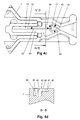
- the upper groove 11 defines on the one hand a path of movement 50 (first guide track) designated with a broken line, and on the other a path of movement 51 (second guide track) designated with a broken line, for the spring end 9, wherein the arrow direction indicates the direction of travel of spring end 9.
- the lower groove 12 in follower member 7 shown in figures 4C, 4D has a deeper portion 38 with a bottom 39 and a shallower portion 40 with a bottom 41, wherein the deeper and shallower portions 38,40 connect to each other via stepped transitions 46.
- An elevation 42 with a stop surface 43 for spring end 10 extends between the deeper and shallower portions 38,40.
- the lower groove 12 defines on the one hand a path 52 (third guide track) designated with a broken line, and on the other a path of movement 53 (fourth guide track), designated with a broken line, for spring end 10, wherein the arrow direction indicates the direction of displacement/travel of spring end 10.
- window 47 When window 47 is released from the position shown in fig. 6D, profile 3 will initially slide back slightly into housing 2.
- follower member 7 herein remains in place along housing 2 as a result of the friction between these two, and spring ends 9,10 displace along the respective grooves 11,12 as shown by broken lines in fig. 7.
- Spring end 9 herein moves over the stepped transition 34 of the obliquely rising part 33. Due to the relative displacement between follower member 7 and assembly part 6, blocking element 15 will tilt until gripping edge 16 comes into blocking engagement with the inner surface of housing 2; this latter blocking position of blocking element 15 is shown in fig. 7. Further sliding of profile 3 back into housing 2 is then not possible: window 47 is blocked in the open position shown in fig. 7D by movement back from the position shown in fig. 6D (this latter position is shown with a broken line in fig. 7D).
- window 47 When it is then desired to close window 47, window 47 must first be pushed open slightly to the position shown in fig. 8D from the position shown in fig. 7D (this latter position is shown with a broken line in fig. 8D).
- Profile 3 herein slides out of housing 2, follower member 7 again initially remains in place along housing 2, and spring ends 9,10 displace along the respective grooves 11,12 as shown by broken lines in fig. 8.
- Spring end 9 herein displaces in transverse direction counter to the bias in the manner indicated; because of the stepped transition 34 and because spring end 9 is pressed onto the bottom of groove 11 in thickness direction thereof by the bias, spring end 9 can after all not move back along the stepped transition 34. Due to this opening movement blocking element 15 will tilt as a result of the relative displacement between follower member 7 and assembly part 6, so that gripping edge 16 is released from housing 2, so that blocking of the closing movement is ended.
- window 47 With device 1 it is thus only necessary in order to open a window 47 to push window 47 open to a desired open position and to then release window 47. Window 47 is then automatically blocked in the open position. In order to close window 47 it is only necessary to push window 47 open slightly from the blocked open position, whereafter window 47 can be fully closed. Opening and closing of window 47 can thus be carried out quickly and easily with device 1, for instance using only one hand. A continuously variable adjustment of the blocked open position of window 47 is possible.
- pressing member 18 Operation of pressing member 18 is described on the one hand from a starting position in which an unblocked closing of the window is possible (fig. 10-13). Operation of pressing member 18 is described on the other hand from a starting position in which the closing movement of the window is blocked (fig. 14-17).
- the spring end 10 will herein displace from the deeper portion 38, over the stepped transition 46 and to shallower portion 40 of groove 12, as shown with a broken line in fig. 11C.
- the spring end 10 here moves in lateral direction past stop surface 43 of elevation 42 so that displacement of spring end 10 past stop surface 43 becomes possible.
- the option of the switching operation through manual/automatic operation of pressing member 18 is for instance useful in the case that a window is connected to an adjacent wall on either side by means of a device 1.
- a situation to occur in which the closing movement is blocked in the one device 1 while the closing movement is not blocked in the other device 1 the devices are not synchronized. Closing of the window is then impossible. Moving the window in the opening direction and then moving the window in the closing direction would after all enable an unblocked closing movement in the one device while the closing movement would conversely be blocked in the other device.
- pressing member 18 of the other, unblocked device 1 in the described situation, a subsequent unblocked closing movement is made possible in this other device 1.
Landscapes
- Engineering & Computer Science (AREA)
- Mechanical Engineering (AREA)
- Window Of Vehicle (AREA)
Abstract
Description
- The invention relates to a device for opening a panel, comprising a first opening arm and a second opening arm which are mutually connected and slidable for respectively an opening movement and a closing movement, blocking means with a blocking position for the purpose of blocking the closing movement and a free position in which the opening arms are freely slidable, and comprising operating means for operating the blocking means, wherein the operating means are able and adapted to alternately place the blocking means in the blocking position and the free position in successive closing movements, and wherein the blocking means are always in a free position during an opening movement.
- Such a device is known from the
German Offenlegungsschrift 34 45 234A . The known device has a housing in which a profile is arranged in extensible manner. The profile can for instance be mounted on a window, and the housing for instance on a window frame. A clamping piece with two resilient clamping legs is provided on the profile. The clamping piece is here displaceable relative to the profile so that, as a result of displacement over oblique edges of the profile in outward direction, the clamping legs can be forced to engage clampingly on the housing. A closing movement can thus be blocked. The clamping piece is provided with a groove-like path of movement into which extends a pin which is mounted hingedly on the profile. Because the clamping piece is displaceable with friction along the housing and with a suitable design of the path of movement the pin will be forced to run along the path of movement during alternate opening and closing movements. The clamping piece herein displaces relative to the profile. The path of movement is embodied such that, during successive closing movements, the clamping legs alternately do and do not engage in blocking manner on the housing. - With the known device it is possible to block the window in an open position by opening the window and then moving the window slightly in the closing direction. The window can then be closed by first opening the window slightly and then closing it. This cycle can then be repeated.
- The known device can for instance be applied on either side of a caravan window of flexible plastic. The known device herein has the drawback that due to torsion of the window a situation can occur wherein the blocking means are relieved in the one device while the blocking means are actuated in the other device. Closing of the window is then not possible. When the window is pushed open from this situation, the blocking means will be actuated in the one device when the window is then moved in the closing direction, while in the other device the blocking means are relieved. Closing of the window is then still not possible. Such a situation can also occur when two known devices are mounted at different angles relative to a window. When the window is opened, the two opening arms of the one device will then undergo a greater mutual displacement than the two opening arms of the other device. In the case of a small opening movement of the window it is then possible that this opening movement is recognized as such by the one device but not by the other device. The two devices can hereby begin to operate asynchronously. The above described situation can further occur when the known devices are mounted on the window, for instance in the factory.
- The invention has for its object, among others, to provide a device of the type described in the preamble, in which this drawback is obviated to at least a significant extent.
- For this purpose a device of the type stated in the preamble has the feature according to the invention that synchronizing means are provided which are able and adapted to act in a starting position of the blocking means during actuation such that they return thereto in a subsequent closing movement. When a device according to the invention is applied on either side of a window, a situation in which the blocking means are in the blocking position in one device while the blocking means are in the free position in another device can be ended as follows. The synchronizing means of the one device are for instance actuated. An opening movement and then a closing movement is then carried out with the window. The blocking means of the one device will then be in the free position once again, since in this example the free position is the starting position. The blocking means of the other device will then also be in the free position. The window can thereby be closed, and the devices are synchronized.
- An embodiment of the device according to the invention has the feature that the synchronizing means are able and adapted to act on the operating means in order to have the blocking means change between the blocking position and the free position.
- A preferred embodiment of the device according to the invention has the feature that the synchronizing means are able and adapted to act on the operating means in order to place the blocking means in an intermediate position, from which the blocking means return to the starting position during a subsequent closing movement. The intermediate position can for instance be reached by making a slight opening movement with the window.
- A particular embodiment of the device according to the invention has the feature that the synchronizing means comprise an operating member which is able and adapted to actuate the synchronizing means when touched.
- A further particular embodiment of the device according to the invention has the feature that the operating member is provided with a manually operated control button.
- Another particular embodiment of the device according to the invention has the feature that one of the two opening arms is provided with a cam which acts on the operating member in an end position of the opening movement. Synchronization of the two devices can thus take place easily and quickly by fully opening the window. In the case that a window cannot be fully opened, for instance the case of a caravan window a short distance from a tree, the above described embodiment of a manually operated control button provides a solution.
- A preferred embodiment of the device according to the invention has the feature that the operating means comprise a follower member for the second opening arm, wherein the follower member is displaceable with friction along the first opening arm, and wherein the follower member has a first guide track and a second guide track, and wherein a first coupling element extends from the second opening arm in order to mutually couple the follower member and the second opening arm, wherein the first coupling element is displaceable along the first guide track, wherein the first coupling element reaches a determined position along the first guide track during each second closing movement, as a result of which the blocking means are placed in the blocking position, and wherein the blocking means are in the free position when the first coupling element is displaced along other positions of the first guide track, and wherein the first coupling element is displaceable along the second guide track, wherein the blocking means are in the free position when the first coupling element is displaced along the second guide track.
- When reversing from a closing movement to an opening movement or vice versa, the first coupling element will displace along the first or second guide track. This is possible because the follower member herein initially remains in place along the first opening arm as a result of friction between the follower member and the first opening arm.
- A further preferred embodiment of the device according to the invention has the feature that the first coupling element describes a first closed, loop-like path when displaced along the first guide track, and that the first coupling element describes a second closed, loop-like path when displaced along the second guide track.
- A particular embodiment of the device according to the invention has the feature that the follower member has a third guide track and a fourth guide track, and wherein a second coupling element extends from the second opening arm in order to mutually couple the follower member and the second opening arm, wherein the second coupling element is displaceable along the third guide track so as to allow displacement of the first coupling element along the first guide track, and wherein the second coupling element is displaceable along the fourth guide track so as to allow displacement of the first coupling element along the second guide track.
- A further particular embodiment of the device according to the invention has the feature that the second coupling element describes a closed loop-like track when displaced along the fourth guide track.
- A preferred embodiment of the device according to the invention has the feature that the blocking means comprise a blocking element with a gripping edge, wherein the blocking element is coupled to the second opening arm and to the follower member, wherein the gripping edge comes into blocking engagement with the first opening arm when the first coupling element reaches the determined position along the first guide track as a result of a corresponding relative displacement of the follower member in relation to the second opening arm.
- The invention will now be further elucidated on the basis of an exemplary embodiment and associated figures. The figures are shown schematically and not (always) drawn to scale. Some dimensions in particular may be exaggerated to a greater or lesser extent for the sake of clarity. Corresponding parts are designated as far as possible in the figures with the same reference numeral.
- Figure 1
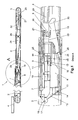
- shows a cross-sectional side view of an exemplary embodiment of the device according to the invention.
- Figures 2A-C
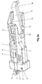
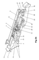
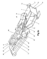
- show perspective views of a follower member and an assembly part therefor, wherein the assembly part is cut-away in figures 2B,2C for the sake of clarity.
- Figures 3A,B
- show a side view and a top view of a torsion spring which is used to mutually couple the follower member and the second opening arm.
- Figures 4A,B
- show respectively a top view of a part of the follower member with the first and second guide track, and a cross-section along line B-B.
- Figures 4C,D
- show respectively a bottom view of a part of the follower member with the third and fourth guide track, and a cross-section along line D-D.
- Figures 5-9
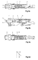
- show respectively top views, side views and bottom views of the assembly part with follower member, in addition to corresponding positions of a window at different stages of opening and closing of the window using the device according to the invention.
- Figures 10-13
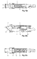
- show respectively top views, side views and bottom views of the assembly part with follower member when the pressing member is operated, during an opening and closing movement from a situation from which an unblocked closing movement is possible.
- Figures 14-17
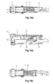
- show respectively top views, side views and bottom views of the assembly part with follower member when the pressing member is operated, during an opening and closing movement from a situation of a blocked closing movement.
- The device 1 shown in figure 1 will be further elucidated hereinbelow using figures 2A, 2B and 2C. Device 1 of figure 1 for opening and closing a window comprises a housing 2 (first opening arm) and a profile 3 (second opening arm) slidable relative to
housing 2 for an opening movement whereinprofile 3 slides out ofhousing 2 and for a closing movement whereinprofile 3 slides back intohousing 2.Housing 2 is provided at an outer end thereof with a mountingelement 4 for mounting on the window, whileprofile 3 is provided at an outer end thereof with a mountingelement 5 for mounting on a wall part which bounds the window. - A
plastic assembly part 6 is clamped fixedly in the outer end ofprofile 3 extending intohousing 2. Aplastic follower member 7 is received slidably inassembly part 6 by means of a snap connection, whereinfollower member 7 andassembly part 6 are further coupled to each other via atorsion spring 8 with anupper leg 44 and alower leg 45. Aspring end 20 oftorsion spring 8 is fixedly clamped for this purpose inopenings 21 ofassembly part 6 by means of a snap connection, while a spring end 9 (first coupling element) extends into an upper groove 11 (not visible in figure 1) infollower member 7 and a spring end 10 (second coupling element) extends into a lower groove 12 (not visible in figure 1) infollower member 7. The spring ends 9,10 are herein displaceable along therespective grooves follower member 7 alongassembly part 6.Torsion spring 8 is embodied such that spring ends 9,10 are received in therespective grooves respective grooves 11,12 (resilience in thickness direction). This bias is indicated in fig. 2B with arrows H,I. -
Follower member 7 hasprotrusions 49 extending on either side thereof and protruding relative toassembly part 6, which havecontact surfaces 19 which lie against the inner surface ofhousing 2 so thatfollower member 7 can be displaced with friction alonghousing 2. Device 1 further has a blockingelement 15 with agripping edge 16 wherein, by tilting blockingelement 15 in the direction indicated in fig. 1 with arrow K, grippingedge 16 is able to engage the inner side ofhousing 2 in blocking manner in order to block further sliding ofprofile 3 into housing 2 (the closing movement is then blocked). For the purpose of tilting blockingelement 15, the blockingelement 15 on the one hand extends through anopening 17 arranged infollower member 7 and on the other hand laterally protrudingtongues 14 of blockingelement 15 are received inopenings 13 arranged inassembly part 6. Blockingelement 15 can thus be tilted as a result of relative displacement betweenfollower member 7 andassembly part 6. In an alternativeembodiment blocking element 15 also has a gripping edge on the opposite side of grippingedge 16. - Device 1 further comprises a plastic pressing
member 18 with apivot shaft 22 mounted onassembly part 6 by means of a snap connection. Pressingmember 18 has aprotrusion 23 which is able to engage onlower leg 45 oftorsion spring 8 through rotation of pressing member 18 (to the right in fig. 1, 2A, 2B) so as to push thespring end 10 slightly downward out ofgroove 12. In order to rotate pressingmember 18 in this manner the pressingmember 18 has on the one hand acam 24 which, by sliding the profile 3 (almost completely) out ofhousing 2, can be brought into contact with a thickenedportion 25 arranged on the inner side of an outer end ofhousing 2. Whencam 24 comes up against thickenedportion 25, pressingmember 18 will rotate so as to press thelower leg 45 downward withprotrusion 23 thereof. On the other hand anoperating arm 31 rotatable about apivot shaft 26 is provided inprofile 3, wherein the oneend 27 of operatingarm 31 is provided with a hand-operatedcontrol button 28 and wherein theother end 29 of operatingarm 31 extends above aportion 30 of pressingmember 18. By pressingcontrol button 28 theoperating arm 31 rotates so that theportion 30 of pressingmember 18 is pressed downward byouter end 29 of operatingarm 31 so as to press thelower leg 45 oftorsion spring 8 downward. Arranged onprofile 3 is aspring 32 for returningoperating arm 31 to the original position again after operation ofcontrol button 28, whereinportion 30 of pressingmember 18 is not pushed downward byouter end 29. - The whole of
assembly part 6,follower member 7,torsion spring 8, blockingelement 15 and pressingmember 18 shown in fig. 2A can be mounted as a unit inprofile 3 so that assembly of device 1 is facilitated. Figures 3A, 3Bshow torsion spring 8 in more detail. - The
upper groove 11 infollower member 7 shown in figures 4A,4B has a bottom 37 in which are arranged an obliquely risingportion 33 with a steppedtransition 34 and an obliquely risingportion 35 with a steppedtransition 36. Except at the location of the obliquely risingportions follower member 7. Theupper groove 11 defines on the one hand a path of movement 50 (first guide track) designated with a broken line, and on the other a path of movement 51 (second guide track) designated with a broken line, for thespring end 9, wherein the arrow direction indicates the direction of travel ofspring end 9. - The
lower groove 12 infollower member 7 shown in figures 4C, 4D has adeeper portion 38 with a bottom 39 and ashallower portion 40 with a bottom 41, wherein the deeper andshallower portions elevation 42 with astop surface 43 forspring end 10 extends between the deeper andshallower portions lower groove 12 defines on the one hand a path 52 (third guide track) designated with a broken line, and on the other a path of movement 53 (fourth guide track), designated with a broken line, forspring end 10, wherein the arrow direction indicates the direction of displacement/travel ofspring end 10. - The normal operation of device 1 for opening and closing a window will be described hereinbelow using figures 5-9 with reference to figures 1-4.
- Starting from the starting position shown in fig. 5, the
profile 3 will slide out ofhousing 2 by pushing open awindow 47 pivoting about ahorizontal shaft 48. Because contact surfaces 19 offollower member 7 lie with friction against the inner surface ofhousing 2,follower member 7 will here initially remain in place alonghousing 2.Assembly part 6 andtorsion spring 8 are however immediately co-displaced byprofile 3 so that spring ends 9, 10 will displace along therespective grooves Spring end 9 will displace in the indicated direction due to the bias in transverse direction. Whenspring end 10 comes up againststop surface 43 ofelevation 42,follower member 7 is then co-displaced byspring end 10 for joint displacement alonghousing 2, and there is no further displacement of spring ends 9,10 alonggrooves Window 47 can thus be pushed open to for instance a position as shown in fig. 6D. - When
window 47 is released from the position shown in fig. 6D,profile 3 will initially slide back slightly intohousing 2.Follower member 7 herein remains in place alonghousing 2 as a result of the friction between these two, and spring ends 9,10 displace along therespective grooves Spring end 9 herein moves over the steppedtransition 34 of the obliquely risingpart 33. Due to the relative displacement betweenfollower member 7 andassembly part 6, blockingelement 15 will tilt until grippingedge 16 comes into blocking engagement with the inner surface ofhousing 2; this latter blocking position of blockingelement 15 is shown in fig. 7. Further sliding ofprofile 3 back intohousing 2 is then not possible:window 47 is blocked in the open position shown in fig. 7D by movement back from the position shown in fig. 6D (this latter position is shown with a broken line in fig. 7D). - When it is then desired to close
window 47,window 47 must first be pushed open slightly to the position shown in fig. 8D from the position shown in fig. 7D (this latter position is shown with a broken line in fig. 8D).Profile 3 herein slides out ofhousing 2,follower member 7 again initially remains in place alonghousing 2, and spring ends 9,10 displace along therespective grooves Spring end 9 herein displaces in transverse direction counter to the bias in the manner indicated; because of the steppedtransition 34 and becausespring end 9 is pressed onto the bottom ofgroove 11 in thickness direction thereof by the bias,spring end 9 can after all not move back along the steppedtransition 34. Due to this openingmovement blocking element 15 will tilt as a result of the relative displacement betweenfollower member 7 andassembly part 6, so that grippingedge 16 is released fromhousing 2, so that blocking of the closing movement is ended. - When
window 47 is moved in the closing direction from the situation shown in fig. 8, spring ends 9,10 will displace along therespective grooves follower member 7 andassembly part 6 is small here however, so that blockingelement 15 will only tilt a little: grippingedge 16 herein does not come into engagement withhousing 2. When spring ends 9,10 have been displaced alonggrooves follower member 7 is carried along byspring end 9 for joint displacement alonghousing 2 so as to enable an unblocked closing movement.Window 48 can thus be closed completely or almost completely to the starting position shown in fig. 5. After the cycle described in figures 5-9 thespring end 9 has followed a closed loop-like path of movement 50 (first guide track) alongupper groove 11, andspring end 10 has been displaced along guide path 52 (third guide track) along thelower groove 12. The above described cycle of figures 5-9 can herein be repeated for subsequent opening and closing ofwindow 47. - With device 1 it is thus only necessary in order to open a
window 47 to pushwindow 47 open to a desired open position and to then releasewindow 47.Window 47 is then automatically blocked in the open position. In order to closewindow 47 it is only necessary to pushwindow 47 open slightly from the blocked open position, whereafterwindow 47 can be fully closed. Opening and closing ofwindow 47 can thus be carried out quickly and easily with device 1, for instance using only one hand. A continuously variable adjustment of the blocked open position ofwindow 47 is possible. - The operation of device 1 will be described hereinbelow in the case that pressing
member 18 is operated. Operation of pressingmember 18 is described on the one hand from a starting position in which an unblocked closing of the window is possible (fig. 10-13). Operation of pressingmember 18 is described on the other hand from a starting position in which the closing movement of the window is blocked (fig. 14-17). - From a starting position as shown in fig. 10, in which unblocked closing of the window is possible, as described in the normal operation of device 1, the
lower spring end 10 will be pushed downward byprotrusion 23 by operating pressingmember 18, as shown in fig. 11B. - As a result of the bias in transverse direction the
spring end 10 will herein displace from thedeeper portion 38, over the steppedtransition 46 and toshallower portion 40 ofgroove 12, as shown with a broken line in fig. 11C. Thespring end 10 here moves in lateral directionpast stop surface 43 ofelevation 42 so that displacement ofspring end 10past stop surface 43 becomes possible. - From the situation shown in fig. 11 the spring ends 9,10 will displace along the
respective grooves Spring end 9 herein moves over steppedtransition 36 via theoblique rising part 35 andspring end 10 herein moves back via steppedtransition 46 to thedeeper portion 38 oflower groove 12. The displacement of spring ends 9,10 alonggrooves protrusions 49 offollower member 7 come to a stop againstassembly part 6. - By then moving the window in the closing direction the spring ends 9,10 displace back along
grooves respective grooves - Assuming a starting position as shown in fig. 14, wherein the closing movement is blocked as described in the normal operation of device 1, the
lower spring end 10 will be pressed downward byprotrusion 23 through operation of pressingmember 18, as shown in fig. 15B. - As a result of the bias in transverse direction the
spring end 10 will herein displace fromdeeper portion 38, over steppedtransition 46 and toshallower portion 40 ofgroove 12, as shown with a broken line in fig. 15C.Spring end 10 can hereby be moved paststop surface 43. - By pushing the window open from the position shown in fig. 15, the spring ends 9,10 will displace along the
respective grooves member 18 in a situation in which the closing movement of the window is blocked does not thus affect a subsequent unblocked closing movement, the device 1 thus acts as described during normal operation. - The option of the switching operation through manual/automatic operation of pressing
member 18 is for instance useful in the case that a window is connected to an adjacent wall on either side by means of a device 1. In that case it is possible, for instance through torsion of the window, for a situation to occur in which the closing movement is blocked in the one device 1 while the closing movement is not blocked in the other device 1: the devices are not synchronized. Closing of the window is then impossible. Moving the window in the opening direction and then moving the window in the closing direction would after all enable an unblocked closing movement in the one device while the closing movement would conversely be blocked in the other device. However, by operating pressingmember 18 of the other, unblocked device 1 in the described situation, a subsequent unblocked closing movement is made possible in this other device 1. From the described situation the window can thereby still be closed after being pushed open slightly: the two devices are synchronized with each other. It makes no difference here whether pressingmember 18 of the one blocked device 1 is also operated in the described situation since this operation does not after all influence a subsequent unblocked closing movement of the one device, as described in figures 14-17. The latter provides convenience of use: it is not first necessary to check first in which device 1 two successive closing movements are made possible by operating pressingmember 18, and to then operate that pressingmember 18. A correct synchronization takes place simply by operating both pressingmembers 18.
Claims (11)
- Device for opening a panel, comprising a first opening arm and a second opening arm which are mutually connected and slidable for respectively an opening movement and a closing movement, blocking means with a blocking position for the purpose of blocking the closing movement and a free position in which the opening arms are freely slidable, and comprising operating means for operating the blocking means, wherein the operating means are able and adapted to alternately place the blocking means in the blocking position and the free position in successive closing movements, and wherein the blocking means are always in a free position during an opening movement, characterized in that synchronizing means are provided which are able and adapted to act in a starting position of the blocking means during actuation such that they return thereto in a subsequent closing movement.
- Device as claimed in claim 1, characterized in that the synchronizing means are able and adapted to act on the operating means in order to have the blocking means change between the blocking position and the free position.
- Device as claimed in claim 1, characterized in that the synchronizing means are able and adapted to act on the operating means in order to place the blocking means in an intermediate position, from which the blocking means return to the starting position during a subsequent closing movement.
- Device as claimed in one or more of the foregoing claims, characterized in that the synchronizing means comprise an operating member which is able and adapted to actuate the synchronizing means when touched.
- Device as claimed in claim 4, characterized in that the operating member is provided with a manually operated control button.
- Device as claimed in claim 4 or 5, characterized in that one of the two opening arms is provided with a cam which acts on the operating member in an end position of the opening movement.
- Device as claimed in one or more of the foregoing claims, characterized in that the operating means comprise a follower member for the second opening arm, wherein the follower member is displaceable with friction along the first opening arm, and wherein the follower member has a first guide track and a second guide track, and wherein a first coupling element extends from the second opening arm in order to mutually couple the follower member and the second opening arm, wherein the first coupling element is displaceable along the first guide track, wherein the first coupling element reaches a determined position along the first guide track during each second closing movement, as a result of which the blocking means are placed in the blocking position, and wherein the blocking means are in the free position when the first coupling element is displaced along other positions of the first guide track, and wherein the first coupling element is displaceable along the second guide track, wherein the blocking means are in the free position when the first coupling element is displaced along the second guide track.
- Device as claimed in claim 7, characterized in that the first coupling element describes a first closed, loop-like path when displaced along the first guide track, and that the first coupling element describes a second closed, loop-like path when displaced along the second guide track.
- Device as claimed in claim 7 or 8, characterized in that the follower member has a third guide track and a fourth guide track, and wherein a second coupling element extends from the second opening arm in order to mutually couple the follower member and the second opening arm, wherein the second coupling element is displaceable along the third guide track so as to allow displacement of the first coupling element along the first guide track, and wherein the second coupling element is displaceable along the fourth guide track so as to allow displacement of the first coupling element along the second guide track.
- Device as claimed in claim 9, characterized in that the second coupling element describes a closed, loop-like track when displaced along the fourth guide track.
- Device as claimed in one or more of the claims 7-10, characterized in that the blocking means comprise a blocking element with a gripping edge, wherein the blocking element is coupled to the second opening arm and to the follower member, wherein the gripping edge comes into blocking engagement with the first opening arm when the first coupling element reaches the determined position along the first guide track as a result of a corresponding relative displacement of the follower member in relation to the second opening arm.
Applications Claiming Priority (1)
| Application Number | Priority Date | Filing Date | Title |
|---|---|---|---|
| NL1029791A NL1029791C2 (en) | 2005-08-24 | 2005-08-24 | Assembly for postponing a panel. |
Publications (1)
| Publication Number | Publication Date |
|---|---|
| EP1764466A1 true EP1764466A1 (en) | 2007-03-21 |
Family
ID=35788322
Family Applications (1)
| Application Number | Title | Priority Date | Filing Date |
|---|---|---|---|
| EP20060017627 Withdrawn EP1764466A1 (en) | 2005-08-24 | 2006-08-24 | Device for opening a panel |
Country Status (2)
| Country | Link |
|---|---|
| EP (1) | EP1764466A1 (en) |
| NL (1) | NL1029791C2 (en) |
Cited By (1)
| Publication number | Priority date | Publication date | Assignee | Title |
|---|---|---|---|---|
| CN110295809A (en) * | 2019-05-31 | 2019-10-01 | 江苏金堂木窗业有限公司 | A kind of solid-wooden window |
Citations (5)
| Publication number | Priority date | Publication date | Assignee | Title |
|---|---|---|---|---|
| DE938467C (en) * | 1953-09-26 | 1956-02-02 | Happich Gmbh Gebr | Door leaf stay for delivery vans or the like. |
| DE2826002A1 (en) * | 1978-06-14 | 1979-12-20 | Mekuwa Metall Kunststoff | Caravan window telescopic opening arm - has cam on sliding control piece engaging and releasing locking latch inside tube |
| DE3445234A1 (en) | 1984-12-12 | 1986-06-12 | Friedhelm 6301 Fernwald Heer | Setting-out device for windows or the like |
| EP0553523A1 (en) * | 1992-02-11 | 1993-08-04 | Kabushiki Kaisha Yagi | Telescopic support arm |
| DE19722565C1 (en) * | 1997-05-28 | 1999-03-04 | Mekuwa Metall Kunststoff | Window prop for mobile home |
-
2005
- 2005-08-24 NL NL1029791A patent/NL1029791C2/en not_active IP Right Cessation
-
2006
- 2006-08-24 EP EP20060017627 patent/EP1764466A1/en not_active Withdrawn
Patent Citations (5)
| Publication number | Priority date | Publication date | Assignee | Title |
|---|---|---|---|---|
| DE938467C (en) * | 1953-09-26 | 1956-02-02 | Happich Gmbh Gebr | Door leaf stay for delivery vans or the like. |
| DE2826002A1 (en) * | 1978-06-14 | 1979-12-20 | Mekuwa Metall Kunststoff | Caravan window telescopic opening arm - has cam on sliding control piece engaging and releasing locking latch inside tube |
| DE3445234A1 (en) | 1984-12-12 | 1986-06-12 | Friedhelm 6301 Fernwald Heer | Setting-out device for windows or the like |
| EP0553523A1 (en) * | 1992-02-11 | 1993-08-04 | Kabushiki Kaisha Yagi | Telescopic support arm |
| DE19722565C1 (en) * | 1997-05-28 | 1999-03-04 | Mekuwa Metall Kunststoff | Window prop for mobile home |
Cited By (1)
| Publication number | Priority date | Publication date | Assignee | Title |
|---|---|---|---|---|
| CN110295809A (en) * | 2019-05-31 | 2019-10-01 | 江苏金堂木窗业有限公司 | A kind of solid-wooden window |
Also Published As
| Publication number | Publication date |
|---|---|
| NL1029791C2 (en) | 2007-02-27 |
Similar Documents
| Publication | Publication Date | Title |
|---|---|---|
| RU2435013C2 (en) | Auxiliary security module for doors equipped with opening "anti-panic" device | |
| JPS6127549B2 (en) | ||
| CA2330794C (en) | Mechanism for selectively operating and locking a pivotable window | |
| US9435149B1 (en) | Vent stop for window sashes | |
| DK3251554T3 (en) | CONNECTOR FOR CONNECTING A TABLE WITH A TABLE | |
| US11118374B2 (en) | Straight action flush lock for casement window and method of operating the same | |
| RU2259881C2 (en) | Pipette for taking samples of liquid with conical head drop mechanism | |
| CN110036165A (en) | Window and door switch mechanism | |
| CN107661027B (en) | Frying and baking machine | |
| US11788323B2 (en) | Door locking device for an electric household appliance, in particular a dishwasher, and electric household appliance provided therewith | |
| EP1764466A1 (en) | Device for opening a panel | |
| EP2202371A1 (en) | A sliding door or window | |
| AU2003235566B2 (en) | A Handle | |
| CA3116902C (en) | Straight action flush lock for casement window and method of operating the same | |
| WO2007074397A2 (en) | Furniture provided with an opening/closing device for sliding doors | |
| CA3064591C (en) | Side action flush lock for casement window and method of operating the same | |
| EP1686225B1 (en) | A handle for turn opening or tilt and turn opening doors or windows. | |
| JP6147204B2 (en) | Locking mechanism operating device and joinery | |
| EP1520951B1 (en) | A sliding device, a window having such a sliding device and a method for mounting a sash in such a window | |
| GB2432189A (en) | Stay comprising latch located between slider and base end | |
| KR200402502Y1 (en) | A door stopper | |
| KR200248023Y1 (en) | Handle of door lock | |
| EP1857908A1 (en) | Latching mechanism for rotating adjustment controls | |
| CN112443200A (en) | Push-pull module of door lock | |
| EP2419588B1 (en) | Snap-acting locking device, particularly for lids, doors and the like |
Legal Events
| Date | Code | Title | Description |
|---|---|---|---|
| PUAI | Public reference made under article 153(3) epc to a published international application that has entered the european phase |
Free format text: ORIGINAL CODE: 0009012 |
|
| AK | Designated contracting states |
Kind code of ref document: A1 Designated state(s): AT BE BG CH CY CZ DE DK EE ES FI FR GB GR HU IE IS IT LI LT LU LV MC NL PL PT RO SE SI SK TR |
|
| AX | Request for extension of the european patent |
Extension state: AL BA HR MK YU |
|
| 17P | Request for examination filed |
Effective date: 20070921 |
|
| 17Q | First examination report despatched |
Effective date: 20071025 |
|
| AKX | Designation fees paid |
Designated state(s): AT BE BG CH CY CZ DE DK EE ES FI FR GB GR HU IE IS IT LI LT LU LV MC NL PL PT RO SE SI SK TR |
|
| RAP1 | Party data changed (applicant data changed or rights of an application transferred) |
Owner name: POLYPLASTIC GROEP B.V. |
|
| GRAP | Despatch of communication of intention to grant a patent |
Free format text: ORIGINAL CODE: EPIDOSNIGR1 |
|
| INTG | Intention to grant announced |
Effective date: 20160314 |
|
| STAA | Information on the status of an ep patent application or granted ep patent |
Free format text: STATUS: THE APPLICATION IS DEEMED TO BE WITHDRAWN |
|
| 18D | Application deemed to be withdrawn |
Effective date: 20160726 |