EP1764278A2 - Automatic stop device and method for internal combustion engine - Google Patents
Automatic stop device and method for internal combustion engine Download PDFInfo
- Publication number
- EP1764278A2 EP1764278A2 EP06254830A EP06254830A EP1764278A2 EP 1764278 A2 EP1764278 A2 EP 1764278A2 EP 06254830 A EP06254830 A EP 06254830A EP 06254830 A EP06254830 A EP 06254830A EP 1764278 A2 EP1764278 A2 EP 1764278A2
- Authority
- EP
- European Patent Office
- Prior art keywords
- clutch
- frictional engagement
- engagement element
- internal combustion
- control member
- Prior art date
- Legal status (The legal status is an assumption and is not a legal conclusion. Google has not performed a legal analysis and makes no representation as to the accuracy of the status listed.)
- Granted
Links
- 238000002485 combustion reaction Methods 0.000 title claims description 23
- 238000000034 method Methods 0.000 title claims description 20
- 230000005540 biological transmission Effects 0.000 claims description 14
- 230000008878 coupling Effects 0.000 abstract 1
- 238000010168 coupling process Methods 0.000 abstract 1
- 238000005859 coupling reaction Methods 0.000 abstract 1
- 239000000446 fuel Substances 0.000 description 5
- 238000010586 diagram Methods 0.000 description 2
- 230000000994 depressogenic effect Effects 0.000 description 1
- 238000001514 detection method Methods 0.000 description 1
- 230000007613 environmental effect Effects 0.000 description 1
- 239000012530 fluid Substances 0.000 description 1
- 230000006870 function Effects 0.000 description 1
- 230000007935 neutral effect Effects 0.000 description 1
Images

Classifications
-
- B—PERFORMING OPERATIONS; TRANSPORTING
- B60—VEHICLES IN GENERAL
- B60W—CONJOINT CONTROL OF VEHICLE SUB-UNITS OF DIFFERENT TYPE OR DIFFERENT FUNCTION; CONTROL SYSTEMS SPECIALLY ADAPTED FOR HYBRID VEHICLES; ROAD VEHICLE DRIVE CONTROL SYSTEMS FOR PURPOSES NOT RELATED TO THE CONTROL OF A PARTICULAR SUB-UNIT
- B60W30/00—Purposes of road vehicle drive control systems not related to the control of a particular sub-unit, e.g. of systems using conjoint control of vehicle sub-units
- B60W30/18—Propelling the vehicle
- B60W30/18009—Propelling the vehicle related to particular drive situations
- B60W30/18018—Start-stop drive, e.g. in a traffic jam
Definitions
- the present invention relates to an automatic stop device and method for an internal combustion engine, and particularly to a technique of automatically stopping the internal combustion engine coupled to a transmission through a frictional engagement element brought into a released state by a driver's operation.
- a vehicle having a manual transmission hereinafter also referred to as an MT
- a clutch is brought into a released state or an engaged state by the operation of a clutch pedal.
- An operation of such an MT vehicle is burdensome in performing a hill-start or in low-speed running, and is difficult for an inexperienced driver. Accordingly, there has been proposed a technique of bringing a clutch into a released state or an engaged state independently of the operation of a clutch pedal.
- Japanese Utility Model Laying-Open No. 05-014664 discloses a vehicle clutch device capable of reducing the burden of operating a clutch pedal.
- the vehicle clutch device described in Japanese Utility Model Laying-Open No. 05-014664 is a vehicle clutch device configured to transfer engine output torque to a transmission through a friction clutch, and to allow the clutch to be released by working hydraulic pressure generated by the operation of the clutch pedal.
- the vehicle clutch device includes a hydraulic pump generating working hydraulic pressure for release independently of the operation of the clutch pedal, an engine rotation speed detecting unit detecting a rotation speed of an engine, a vehicle speed detecting unit detecting a running speed of the vehicle, an accelerator pedal operated amount detecting unit detecting an operated amount of the accelerator pedal, and a hydraulic pressure control unit controlling the working hydraulic pressure for release generated by the hydraulic pump, based on the detected rotation speed of the engine, running speed of the vehicle, and operated amount of the accelerator pedal.
- the device is provided with a hydraulic pump that generates working hydraulic pressure for releasing the clutch independently of the clutch pedal, and the working hydraulic pressure for releasing the clutch, which working hydraulic pressure is generated by the hydraulic pump, is controlled based on the rotation speed of the engine, running speed of the vehicle, and operated amount of the accelerator pedal. Accordingly, when the clutch is required to be engaged and released in a repeated manner in a congested route and the like, it is possible to reduce the burden of the driver operating the clutch pedal.
- idle stop which is also referred to as economy running or eco-run
- Japanese Utility Model Laying-Open No. 05-014664 does not describe that idle stop is performed in a suitable manner in a vehicle where a clutch is engaged or released independently of the clutch pedal.
- An object of the present invention is to provide an automatic stop device and method for an internal combustion engine, the automatic stop device and the method being capable of performing idle stop in a suitable manner.
- An embodiment of the invention provides an automatic stop device for an internal combustion engine that automatically stops the internal combustion engine coupled to a transmission through a frictional engagement element brought into a released state by pressure generated by an operation of an operation unit.
- the automatic stop device includes: a control member provided between the operation unit and the frictional engagement element such that pressure applied to the frictional engagement element is maintained when no electric power is distributed to the control member; and a stop control unit stopping the internal combustion engine when a predetermined stop condition is satisfied.
- the stop condition is at least a condition that the frictional engagement element is in a released state and a condition that an amount of electric power distributed to the control member is smaller than a predetermined value.
- the frictional engagement element is brought into the released state by the pressure generated by the operation of the operation unit.
- the pressure is maintained by stopping electric power distribution to the control member provided between the operation unit and the frictional engagement element.
- the frictional engagement element is maintained in the released state.
- a stop condition which is at least the condition that the frictional engagement element is in the released state and the condition that an amount of electric power distributed to the control member is smaller than the predetermined value, is satisfied, the internal combustion engine is stopped. Accordingly, it is possible to perform idle stop while electric power distribution to the control member is reduced and the frictional engagement element is maintained in the released state.
- the frictional engagement element is brought into the released state by hydraulic pressure generated by the operation of the operation unit.
- the control member shuts off an oil passage connecting the operation unit and the frictional engagement element when no electric power is distributed to the control member.
- the frictional engagement element is brought into the released state by hydraulic pressure.
- the control member shuts off the oil passage connecting the operation unit and the frictional engagement element, so that the hydraulic pressure applied to the frictional engagement element is maintained. It is therefore possible to maintain the frictional engagement element in the released state. Accordingly, it is possible to prevent the vehicle from accidentally moving when the internal combustion engine is restarted, and perform idle stop in a suitable manner.
- An embodiment of the invention provides a method of automatically stopping an internal combustion engine for automatically stopping an internal combustion engine coupled to a transmission through a frictional engagement element brought into a released state by pressure generated by an operation of an operation unit.
- the automatically stopping method includes the steps of: determining whether or not the frictional engagement element is in the released state; determining whether or not an amount of electric power distributed to a control member is smaller than a predetermined value, the control member being provided between the operation unit and the frictional engagement element for maintaining pressure applied to the frictional engagement element when no electric power is distributed thereto; and stopping the internal combustion engine on conditions that it is determined that the frictional engagement element is in the released state, and that it is determined that the amount of electric power distributed to the control member is smaller than the predetermined value.
- the frictional engagement element is brought into the released state by the pressure generated by the operation of the operation unit.
- the pressure is maintained by stopping electric power distribution to the control member provided between the operation unit and the frictional engagement element.
- the frictional engagement element is maintained in the released state.
- the internal combustion engine is stopped. Accordingly, it is possible to perform idle stop while electric power distribution to the control member is reduced and the frictional engagement element is maintained in the released state.
- the power train includes an engine 100, a clutch 200, and a transmission 300. Torque of engine 100 is transferred to transmission 300 through clutch 200. The torque transferred to a transmission 300 is transferred to a driving wheel (not shown) through a drive shaft (not shown).
- the automatic stop device according to the present embodiment is implemented with a program executed by, for example, an electronic control unit (ECU) 650.
- ECU electronice control unit
- Transmission 300 is a manual transmission in which a driver operates a shift lever 500 for gear shifting.
- the gear shifting in transmission 300 may be performed by an actuator, based on the driver's shift operation.
- Clutch 200 is a dry-type single plate friction clutch. As shown in Fig. 2, clutch 200 includes a clutch output shaft 202, a clutch disk 204 provided at clutch output shaft 202, a clutch housing 206, a pressure plate 208 provided at clutch housing 206, a diaphragm spring 210, a clutch release cylinder 212, a release fork 214, and a release sleeve 216.
- Clutch release cylinder 212 operates by hydraulic pressure being supplied from a master cylinder 402 through a solenoid valve 406. When hydraulic pressure is supplied to clutch release cylinder 212, a piston of clutch release cylinder 212 moves to the left in Fig. 2, and hence release sleeve 216 moves to the right in Fig. 2, so that clutch is released.
- Solenoid valve 406 is a three-way valve of a normally-closed type that shuts off a path from master cylinder 402 to clutch release cylinder 212 when no electric power is distributed thereto.
- a valve other than the three-way valve may be used for solenoid valve 406.
- clutch 200 When clutch 200 is in a released state, electric power distribution to solenoid valve 406 is stopped, so that the hydraulic pressure introduced from master cylinder 402 into clutch release cylinder 212 is maintained. Accordingly, even if the driver lifts his/her foot from clutch pedal 400, clutch 200 is maintained in the released state.
- a flow rate of hydraulic fluid returned from clutch release cylinder 212 to master cylinder 402 is adjusted with solenoid valve 406, and thereby clutch 200 is brought into the engaged state in a desired manner. In other words, clutch 200 is engaged slowly or quickly.
- signals indicative of detection results are input to ECU 650 from a clutch pedal stroke sensor 700, an accelerator pedal position sensor 702, an amperemeter 704, and a stroke sensor 706.
- Clutch pedal stroke sensor 700 detects an operated amount (a stroke amount) of clutch pedal 400.
- Accelerator pedal position sensor 702 detects a position of an accelerator pedal.
- Amperemeter 704 detects a value of current distributed to solenoid valve 406.
- Stroke sensor 706 detects a stroke amount of clutch release cylinder 212.
- ECU 650 controls the power train to be in a desired state, based on the signals transmitted from these sensors and a map stored in a memory (not shown). In the present embodiment, ECU 650 performs idle stop, namely, automatically stops engine 100, when a predetermined stop condition is satisfied.
- ECU 650 detects a stroke amount SP of the clutch pedal, based on the signal transmitted from clutch pedal stroke sensor 700. Furthermore, ECU 650 detects a value I of current distributed to solenoid valve 406, based on the signal transmitted from amperemeter 704. Furthermore, ECU 650 detects a stroke amount SC of clutch release cylinder 212, based on the signal transmitted from stroke sensor 706.
- ECU 650 determines whether or not a condition that stroke amount SP of the clutch pedal is at least a threshold value SP(0), a condition that stroke amount SC of clutch release cylinder 212 is at least a threshold value SC(0), and a condition that value I of current is not larger than a threshold value 1(0) are all satisfied. If all the conditions are satisfied (YES in S102), the process proceeds to S104. If not so (NO in S102), the process terminates.
- ECU 650 permits performing of idle stop.
- ECU 650 determines whether or not a condition for performing idle stop is established.
- the condition for performing idle stop is, for example, a condition that a vehicle speed is not higher than a threshold value, or a condition that a brake pedal is depressed. If the performing condition is established (YES in S106), the process proceeds to S108. If not so (NO in S106), the process returns to S100.
- ECU 650 stops engine 100.
- ECU 650 determines whether or not a condition for restarting engine 100 is established.
- the condition for restarting engine 100 is, for example, a condition that an accelerator pedal position is at least a threshold value, or a condition that clutch pedal 400 is operated again after the driver lifts his/her foot from clutch pedal 400. If the restarting condition is established (YES in S110), the process proceeds to S112. If not so (NO in S110), the process returns to S110. In S112, ECU 650 restarts engine 100. Thereafter the process terminates.
- ECU 650 serving as the automatic stop device according to the present embodiment, based on the configuration and the flowchart above, will be described.
- stroke amount SP of the clutch pedal While the vehicle is driven, stroke amount SP of the clutch pedal, value I of current distributed to solenoid valve 406, and stroke amount SC of clutch release cylinder 212 are detected (S100).
- stroke amount SC of clutch release cylinder 212 turns to be at least threshold value SC(0)
- stroke amount SP of the clutch pedal turns to be at least threshold value SP(0), so that clutch 200 is released.
- electric power distribution to solenoid valve 406 is stopped, so that value I of current flowing through solenoid valve 406 turns to be not larger than threshold value I(0) (S102).
- the ECU serving as the automatic stop device when it is recognized that no electric power is distributed to the solenoid valve of a normally-closed type in a state where the clutch is recognized as being in the released state from stroke amount SP of the clutch pedal and stroke amount SC of the clutch release cylinder, performing of idle stop is permitted. Accordingly, when power consumption in the solenoid valve is small, idle stop can be performed. It is possible to reduce power consumption in the vehicle, and eventually further improve fuel efficiency. In addition, idle stop is performed while the clutch is brought into the released state, and hence it is possible to prevent the vehicle from accidentally moving when the engine is restarted.
- stroke amount SP of clutch pedal 400 and stroke amount SC of clutch release cylinder 212 are used to determine the state of clutch 200.
- hydraulic pressure output from master cylinder 402 may be used.
- Performing of idle stop is permitted when clutch 200 is maintained in the released state. However, in addition to this, performing of idle stop may be permitted when transmission 300 is in a neutral state.
Landscapes
- Engineering & Computer Science (AREA)
- Automation & Control Theory (AREA)
- Transportation (AREA)
- Mechanical Engineering (AREA)
- Hydraulic Clutches, Magnetic Clutches, Fluid Clutches, And Fluid Joints (AREA)
- Control Of Vehicle Engines Or Engines For Specific Uses (AREA)
- Output Control And Ontrol Of Special Type Engine (AREA)
Abstract
Description
- This application is based on
Japanese Patent Application No. 2005-272202 - The present invention relates to an automatic stop device and method for an internal combustion engine, and particularly to a technique of automatically stopping the internal combustion engine coupled to a transmission through a frictional engagement element brought into a released state by a driver's operation.
- There has conventionally been known a vehicle having a manual transmission (hereinafter also referred to as an MT) mounted thereon. In the MT, a clutch is brought into a released state or an engaged state by the operation of a clutch pedal. An operation of such an MT vehicle is burdensome in performing a hill-start or in low-speed running, and is difficult for an inexperienced driver. Accordingly, there has been proposed a technique of bringing a clutch into a released state or an engaged state independently of the operation of a clutch pedal.
-
Japanese Utility Model Laying-Open No. 05-014664 Japanese Utility Model Laying-Open No. 05-014664 - According to the vehicle clutch device described in the publication, the device is provided with a hydraulic pump that generates working hydraulic pressure for releasing the clutch independently of the clutch pedal, and the working hydraulic pressure for releasing the clutch, which working hydraulic pressure is generated by the hydraulic pump, is controlled based on the rotation speed of the engine, running speed of the vehicle, and operated amount of the accelerator pedal. Accordingly, when the clutch is required to be engaged and released in a repeated manner in a congested route and the like, it is possible to reduce the burden of the driver operating the clutch pedal.
- In recent years, owing to increased awareness of environmental issues, more fuel-efficient vehicles are demanded. As a method of improving fuel efficiency of the vehicle, there has been known a technique called idle stop (which is also referred to as economy running or eco-run) with which an engine is automatically stopped when a vehicle temporarily stops at a red light and the like. However,
Japanese Utility Model Laying-Open No. 05-014664 - An object of the present invention is to provide an automatic stop device and method for an internal combustion engine, the automatic stop device and the method being capable of performing idle stop in a suitable manner.
- The invention is defined in the appended claims.
- An embodiment of the invention provides an automatic stop device for an internal combustion engine that automatically stops the internal combustion engine coupled to a transmission through a frictional engagement element brought into a released state by pressure generated by an operation of an operation unit. The automatic stop device includes: a control member provided between the operation unit and the frictional engagement element such that pressure applied to the frictional engagement element is maintained when no electric power is distributed to the control member; and a stop control unit stopping the internal combustion engine when a predetermined stop condition is satisfied. The stop condition is at least a condition that the frictional engagement element is in a released state and a condition that an amount of electric power distributed to the control member is smaller than a predetermined value.
- In an embodiment of the present invention, the frictional engagement element is brought into the released state by the pressure generated by the operation of the operation unit. The pressure is maintained by stopping electric power distribution to the control member provided between the operation unit and the frictional engagement element. In other words, when electric power distribution to the control member is stopped after the frictional engagement element is brought into the released state, the frictional engagement element is maintained in the released state. After that, if a stop condition, which is at least the condition that the frictional engagement element is in the released state and the condition that an amount of electric power distributed to the control member is smaller than the predetermined value, is satisfied, the internal combustion engine is stopped. Accordingly, it is possible to perform idle stop while electric power distribution to the control member is reduced and the frictional engagement element is maintained in the released state. At that time, electric power distribution to the control member is reduced, and hence fuel efficiency can further be improved. Furthermore, the frictional engagement element is in the released state, and hence it is possible to prevent the vehicle from accidentally moving when the internal combustion engine is restarted. It is therefore possible to provide an automatic stop device for an internal combustion engine, the automatic stop device being capable of performing idle stop in a suitable manner.
- In an example embodiment, the frictional engagement element is brought into the released state by hydraulic pressure generated by the operation of the operation unit. The control member shuts off an oil passage connecting the operation unit and the frictional engagement element when no electric power is distributed to the control member.
- In an example embodiment the frictional engagement element is brought into the released state by hydraulic pressure. When electric power distribution to the control member is stopped, the control member shuts off the oil passage connecting the operation unit and the frictional engagement element, so that the hydraulic pressure applied to the frictional engagement element is maintained. It is therefore possible to maintain the frictional engagement element in the released state. Accordingly, it is possible to prevent the vehicle from accidentally moving when the internal combustion engine is restarted, and perform idle stop in a suitable manner.
- An embodiment of the invention provides a method of automatically stopping an internal combustion engine for automatically stopping an internal combustion engine coupled to a transmission through a frictional engagement element brought into a released state by pressure generated by an operation of an operation unit. The automatically stopping method includes the steps of: determining whether or not the frictional engagement element is in the released state; determining whether or not an amount of electric power distributed to a control member is smaller than a predetermined value, the control member being provided between the operation unit and the frictional engagement element for maintaining pressure applied to the frictional engagement element when no electric power is distributed thereto; and stopping the internal combustion engine on conditions that it is determined that the frictional engagement element is in the released state, and that it is determined that the amount of electric power distributed to the control member is smaller than the predetermined value.
- In an embodiment of the present invention, the frictional engagement element is brought into the released state by the pressure generated by the operation of the operation unit. The pressure is maintained by stopping electric power distribution to the control member provided between the operation unit and the frictional engagement element. In other words, when electric power distribution to the control member is stopped after the frictional engagement element is brought into the released state, the frictional engagement element is maintained in the released state. After that, on conditions that it is determined that the frictional engagement element is in the released state and that it is determined that an amount of electric power distributed to the control member is smaller than the predetermined value, the internal combustion engine is stopped. Accordingly, it is possible to perform idle stop while electric power distribution to the control member is reduced and the frictional engagement element is maintained in the released state. At that time, electric power distribution to the control member is reduced, and hence fuel efficiency can further be improved. Furthermore, the frictional engagement element is in the released state, and hence it is possible to prevent the vehicle from accidentally moving when the internal combustion engine is restarted. It is therefore possible to provide an automatic stop method for an internal combustion engine, the automatic stop method being capable of performing idle stop in a suitable manner.
- The foregoing and other objects, features, aspects and advantages of the present invention will become more apparent from the following detailed description of the present invention when taken in conjunction with the accompanying drawings.
-
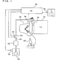
- Fig. 1 is a schematic configuration diagram showing a power train of a vehicle on which an automatic stop device according to the present embodiments is mounted.
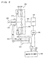
- Fig. 2 is a diagram showing a clutch in Fig. 1.
- Fig. 3 is a flowchart showing a control structure of a program executed by an ECU in Fig. 1
- An embodiment of the present invention will hereinafter be described with reference to the drawings. In the following description, the same parts are denoted by the same reference characters, and the names and functions thereof are the same. Accordingly, the detailed description thereof will not be repeated.
- Referring to Fig. 1, a power train of a vehicle having an automatic stop device according to the embodiment of the present invention mounted thereon will be described. The power train includes an
engine 100, aclutch 200, and atransmission 300. Torque ofengine 100 is transferred totransmission 300 throughclutch 200. The torque transferred to atransmission 300 is transferred to a driving wheel (not shown) through a drive shaft (not shown). The automatic stop device according to the present embodiment is implemented with a program executed by, for example, an electronic control unit (ECU) 650. - When a driver depresses a
clutch pedal 400,clutch 200 is released thereby. Clutch 200 will be described later. Transmission 300 is a manual transmission in which a driver operates ashift lever 500 for gear shifting. The gear shifting intransmission 300 may be performed by an actuator, based on the driver's shift operation. - Referring to Fig. 2,
clutch 200 will further be described.Clutch 200 is a dry-type single plate friction clutch. As shown in Fig. 2, clutch 200 includes aclutch output shaft 202, aclutch disk 204 provided atclutch output shaft 202, aclutch housing 206, apressure plate 208 provided atclutch housing 206, adiaphragm spring 210, aclutch release cylinder 212, arelease fork 214, and arelease sleeve 216. - When diaphragm
spring 210biases pressure plate 208 to the right in Fig. 2,clutch disk 204 is thereby pressed against aflywheel 602 attached to acrankshaft 600 ofengine 100, so that clutch 200 is engaged. - When
clutch release cylinder 212 moves releasesleeve 216 to the right in Fig. 2 throughrelease fork 214, an inner end ofdiaphragm spring 210 thereby moves to the right in Fig. 2. When the inner end ofdiaphragm spring 210 moves to the right in Fig. 2,pressure plate 208 moves to the left in Fig. 2, and henceclutch disk 204 andflywheel 602 are separated, so that clutch 200 is released. -
Clutch release cylinder 212 operates by hydraulic pressure being supplied from amaster cylinder 402 through asolenoid valve 406. When hydraulic pressure is supplied toclutch release cylinder 212, a piston ofclutch release cylinder 212 moves to the left in Fig. 2, and hence releasesleeve 216 moves to the right in Fig. 2, so that clutch is released. - When the driver depresses
clutch pedal 400, hydraulic pressure is generated inmaster cylinder 402. The hydraulic pressure generated inmaster cylinder 402 is introduced intoclutch release cylinder 212 through apipe 404.Pipe 404 is provided withsolenoid valve 406. The hydraulic pressure generated inmaster cylinder 402 is introduced intoclutch release cylinder 212 throughsolenoid valve 406. -
Solenoid valve 406 is a three-way valve of a normally-closed type that shuts off a path frommaster cylinder 402 toclutch release cylinder 212 when no electric power is distributed thereto. A valve other than the three-way valve may be used forsolenoid valve 406. - When the driver depresses
clutch pedal 400 while clutch 200 is in an engaged state, electric power distribution tosolenoid valve 406 starts, so thatmaster cylinder 402 is brought into communication withclutch release cylinder 212. The hydraulic pressure generated inmaster cylinder 402 is thereby introduced intoclutch release cylinder 212 throughsolenoid valve 406. - When clutch 200 is in a released state, electric power distribution to
solenoid valve 406 is stopped, so that the hydraulic pressure introduced frommaster cylinder 402 intoclutch release cylinder 212 is maintained. Accordingly, even if the driver lifts his/her foot fromclutch pedal 400, clutch 200 is maintained in the released state. - For example, if a condition that the driver depresses an accelerator pedal or other conditions is established, electric power distribution to
solenoid valve 406 restarts, so thatmaster cylinder 402 is brought into communication withclutch release cylinder 212. Accordingly, bias force ofdiaphragm spring 210 moves the piston ofclutch release cylinder 212 to the right in Fig. 2, so that clutch 200 is brought back into the engaged state. - At that time, a flow rate of hydraulic fluid returned from
clutch release cylinder 212 tomaster cylinder 402 is adjusted withsolenoid valve 406, and thereby clutch 200 is brought into the engaged state in a desired manner. In other words, clutch 200 is engaged slowly or quickly. - Referring to Fig. 1 again, signals indicative of detection results are input to
ECU 650 from a clutchpedal stroke sensor 700, an acceleratorpedal position sensor 702, anamperemeter 704, and astroke sensor 706. - Clutch
pedal stroke sensor 700 detects an operated amount (a stroke amount) ofclutch pedal 400. Acceleratorpedal position sensor 702 detects a position of an accelerator pedal.Amperemeter 704 detects a value of current distributed tosolenoid valve 406.Stroke sensor 706 detects a stroke amount ofclutch release cylinder 212. -
ECU 650 controls the power train to be in a desired state, based on the signals transmitted from these sensors and a map stored in a memory (not shown). In the present embodiment,ECU 650 performs idle stop, namely, automatically stopsengine 100, when a predetermined stop condition is satisfied. - Referring to Fig. 3, a control structure of a program executed by
ECU 650 serving as an automatic stop device according to the present embodiment will be described. - In step (hereinafter abbreviated as S) 100,
ECU 650 detects a stroke amount SP of the clutch pedal, based on the signal transmitted from clutchpedal stroke sensor 700. Furthermore,ECU 650 detects a value I of current distributed tosolenoid valve 406, based on the signal transmitted fromamperemeter 704. Furthermore,ECU 650 detects a stroke amount SC ofclutch release cylinder 212, based on the signal transmitted fromstroke sensor 706. - In S102,
ECU 650 determines whether or not a condition that stroke amount SP of the clutch pedal is at least a threshold value SP(0), a condition that stroke amount SC ofclutch release cylinder 212 is at least a threshold value SC(0), and a condition that value I of current is not larger than a threshold value 1(0) are all satisfied. If all the conditions are satisfied (YES in S102), the process proceeds to S104. If not so (NO in S102), the process terminates. - In S104,
ECU 650 permits performing of idle stop. In S106,ECU 650 determines whether or not a condition for performing idle stop is established. The condition for performing idle stop is, for example, a condition that a vehicle speed is not higher than a threshold value, or a condition that a brake pedal is depressed. If the performing condition is established (YES in S106), the process proceeds to S108. If not so (NO in S106), the process returns to S100. - In S108,
ECU 650 stopsengine 100. In S110,ECU 650 determines whether or not a condition for restartingengine 100 is established. The condition for restartingengine 100 is, for example, a condition that an accelerator pedal position is at least a threshold value, or a condition thatclutch pedal 400 is operated again after the driver lifts his/her foot fromclutch pedal 400. If the restarting condition is established (YES in S110), the process proceeds to S112. If not so (NO in S110), the process returns to S110. In S112,ECU 650 restartsengine 100. Thereafter the process terminates. - An operation of
ECU 650 serving as the automatic stop device according to the present embodiment, based on the configuration and the flowchart above, will be described. - While the vehicle is driven, stroke amount SP of the clutch pedal, value I of current distributed to
solenoid valve 406, and stroke amount SC ofclutch release cylinder 212 are detected (S100). - Assume that the driver depresses
clutch pedal 400 to bring clutch 200 into the released state. In this case, stroke amount SC ofclutch release cylinder 212 turns to be at least threshold value SC(0), and stroke amount SP of the clutch pedal turns to be at least threshold value SP(0), so that clutch 200 is released. Then electric power distribution tosolenoid valve 406 is stopped, so that value I of current flowing throughsolenoid valve 406 turns to be not larger than threshold value I(0) (S102). - In this case, even if the driver lifts his/her foot from
clutch pedal 400, clutch 200 is maintained in the released state. In such a state, performing of idle stop is permitted (S104). In this state, if the condition for performing idle stop is established (YES in S106),engine 100 is stopped (S108). - In other words, at least a condition including the condition that clutch 200 is in the released state, and the condition that the amount of electric power distributed to
solenoid valve 406 is smaller than the threshold value is satisfied, idle stop is performed. - Accordingly, when electric power consumption in
solenoid valve 406 is small, idle stop can be performed. It is therefore possible to reduce power consumption in the vehicle, and eventually further improve fuel efficiency. - Afterwards, if the restarting condition is established (YES in S110),
engine 100 is restarted (S112). At that time,clutch 200 is in the released state, and hence it is possible to prevent the vehicle from accidentally moving. - As described above, according to the ECU serving as the automatic stop device according to the present embodiment, when it is recognized that no electric power is distributed to the solenoid valve of a normally-closed type in a state where the clutch is recognized as being in the released state from stroke amount SP of the clutch pedal and stroke amount SC of the clutch release cylinder, performing of idle stop is permitted. Accordingly, when power consumption in the solenoid valve is small, idle stop can be performed. It is possible to reduce power consumption in the vehicle, and eventually further improve fuel efficiency. In addition, idle stop is performed while the clutch is brought into the released state, and hence it is possible to prevent the vehicle from accidentally moving when the engine is restarted.
- In the present embodiment, stroke amount SP of
clutch pedal 400 and stroke amount SC ofclutch release cylinder 212 are used to determine the state ofclutch 200. However, in place of, or in addition to the stroke amounts, hydraulic pressure output frommaster cylinder 402 may be used. - Performing of idle stop is permitted when clutch 200 is maintained in the released state. However, in addition to this, performing of idle stop may be permitted when
transmission 300 is in a neutral state. - Although the present invention has been described and illustrated in detail, it is clearly understood that the same is by way of illustration and example only and is not to be taken by way of limitation.
Claims (4)
- An automatic stop device for an internal combustion engine coupled to a transmission (300) through a frictional engagement element (200) brought into a released state by pressure generated by an operation of an operation unit (400), comprising:a control member (406) provided between said operation unit and said frictional engagement element such that pressure applied to said frictional engagement element is maintained when no electric power is distributed to the control member; andstop control means (650) for stopping said internal combustion engine (100) when a predetermined stop condition is satisfied,said stop condition being at least a condition that said frictional engagement element is in the released state and a condition that an amount of electric power distributed to said control member is smaller than a predetermined value.
- The automatic stop device for the internal combustion engine according to claim 1, wherein
said frictional engagement element is brought into the released state by hydraulic pressure generated by the operation of said operation unit, and
said control member shuts off an oil passage (404) connecting said operation unit and said frictional engagement element when no electric power is distributed to the control member. - The automatic stop device for an internal combustion engine according to claim 1 or claim 2, wherein the stop control means comprises a stop control unit.
- A method of automatically stopping an internal combustion engine coupled to a transmission (300) through a frictional engagement element (200) brought into a released state by pressure generated by an operation of an operation unit (400), comprising the steps of:determining whether or not said frictional engagement element is in the released state;determining whether or not an amount of electric power distributed to a control member (406) is smaller than a predetermined value, the control member being provided between said operation unit and said frictional engagement element for maintaining pressure applied to said frictional engagement element when no electric power is distributed thereto; andstopping said internal combustion engine on conditions that it is determined that said frictional engagement element is in the released state, and that it is determined that the amount of electric power distributed to said control member is smaller than the predetermined value.
Applications Claiming Priority (1)
| Application Number | Priority Date | Filing Date | Title |
|---|---|---|---|
| JP2005272202A JP4810942B2 (en) | 2005-09-20 | 2005-09-20 | Automatic stop device for internal combustion engine |
Publications (3)
| Publication Number | Publication Date |
|---|---|
| EP1764278A2 true EP1764278A2 (en) | 2007-03-21 |
| EP1764278A3 EP1764278A3 (en) | 2009-09-02 |
| EP1764278B1 EP1764278B1 (en) | 2011-09-07 |
Family
ID=37494988
Family Applications (1)
| Application Number | Title | Priority Date | Filing Date |
|---|---|---|---|
| EP06254830A Not-in-force EP1764278B1 (en) | 2005-09-20 | 2006-09-18 | Automatic stop device and method for internal combustion engine |
Country Status (4)
| Country | Link |
|---|---|
| US (1) | US7534196B2 (en) |
| EP (1) | EP1764278B1 (en) |
| JP (1) | JP4810942B2 (en) |
| AT (1) | ATE523400T1 (en) |
Cited By (1)
| Publication number | Priority date | Publication date | Assignee | Title |
|---|---|---|---|---|
| EP2301818A3 (en) * | 2009-09-25 | 2013-05-22 | Aisin Seiki Kabushiki Kaisha | Automatic stop and start control system for internal combustion engine |
Families Citing this family (4)
| Publication number | Priority date | Publication date | Assignee | Title |
|---|---|---|---|---|
| JP4368902B2 (en) * | 2007-04-20 | 2009-11-18 | 富士通テン株式会社 | Eco-run control device and control method |
| KR101013838B1 (en) * | 2007-07-13 | 2011-02-14 | 기아자동차주식회사 | Control Method for Idle Stop Entry in Hybrid Vehicles |
| EP2287488B1 (en) * | 2008-06-04 | 2014-01-22 | Nissan Motor Co., Ltd. | Fastening pressure control device for starting friction element at time of controlling idle stop of vehicle |
| CN106461068A (en) * | 2014-06-11 | 2017-02-22 | 博格华纳公司 | Control system for manual transmissions |
Citations (1)
| Publication number | Priority date | Publication date | Assignee | Title |
|---|---|---|---|---|
| JPH0514664A (en) | 1991-07-08 | 1993-01-22 | Toshiba Corp | Equipment |
Family Cites Families (18)
| Publication number | Priority date | Publication date | Assignee | Title |
|---|---|---|---|---|
| JPS6375323A (en) | 1986-09-19 | 1988-04-05 | Maruichi Eng Kk | Automatic stop-start device for vehicle engine |
| JPS63248936A (en) | 1987-04-03 | 1988-10-17 | Plus:Kk | Automatic stopping and starting device for vehicle |
| JPH07106506B2 (en) | 1988-08-19 | 1995-11-15 | 株式会社ダイフク | Nut runner |
| FR2666819B1 (en) | 1990-09-19 | 1994-09-23 | Inst Aluminievoi Magnievoi | METHOD AND DEVICE FOR MANUFACTURING A COMPOSITE MATERIAL FROM A BASE METAL. |
| JPH051592A (en) | 1991-01-31 | 1993-01-08 | Suzuki Motor Corp | Engine automatic stop start control device |
| JPH0514664U (en) * | 1991-08-06 | 1993-02-26 | 日本電子機器株式会社 | Vehicle clutch device |
| JPH0552372A (en) | 1991-08-22 | 1993-03-02 | Tdk Corp | Humidifier |
| JP2868974B2 (en) * | 1993-06-16 | 1999-03-10 | 三菱電機株式会社 | Automatic engine start / stop device |
| JP3671569B2 (en) | 1996-12-27 | 2005-07-13 | いすゞ自動車株式会社 | Clutch interrupting device |
| JP3438605B2 (en) * | 1998-09-17 | 2003-08-18 | トヨタ自動車株式会社 | Control device for automatic clutch vehicle |
| JP2000303870A (en) | 1999-04-23 | 2000-10-31 | Denso Corp | Vehicle control system, roadside device, and automatic control device for internal combustion engine |
| JP2002021597A (en) * | 2000-07-05 | 2002-01-23 | Suzuki Motor Corp | Automatic stop / start control system for engine |
| FR2812919B1 (en) * | 2000-08-11 | 2006-10-20 | Valeo | METHOD FOR CONTROLLING A CLUTCH IN A MOTOR VEHICLE |
| JP3714266B2 (en) * | 2002-03-15 | 2005-11-09 | 日産自動車株式会社 | Auxiliary drive device for idle stop car |
| JP2004076897A (en) * | 2002-08-21 | 2004-03-11 | Toyota Motor Corp | In-vehicle clutch control device |
| JP4026133B2 (en) * | 2003-01-21 | 2007-12-26 | スズキ株式会社 | Control device for hybrid vehicle |
| US7079941B2 (en) * | 2004-03-29 | 2006-07-18 | Mazda Motor Corporation | Engine starting system |
| JP4529866B2 (en) * | 2005-10-27 | 2010-08-25 | コベルコ建機株式会社 | Hybrid construction machine |
-
2005
- 2005-09-20 JP JP2005272202A patent/JP4810942B2/en not_active Expired - Fee Related
-
2006
- 2006-09-18 US US11/522,392 patent/US7534196B2/en not_active Expired - Fee Related
- 2006-09-18 EP EP06254830A patent/EP1764278B1/en not_active Not-in-force
- 2006-09-18 AT AT06254830T patent/ATE523400T1/en not_active IP Right Cessation
Patent Citations (1)
| Publication number | Priority date | Publication date | Assignee | Title |
|---|---|---|---|---|
| JPH0514664A (en) | 1991-07-08 | 1993-01-22 | Toshiba Corp | Equipment |
Cited By (1)
| Publication number | Priority date | Publication date | Assignee | Title |
|---|---|---|---|---|
| EP2301818A3 (en) * | 2009-09-25 | 2013-05-22 | Aisin Seiki Kabushiki Kaisha | Automatic stop and start control system for internal combustion engine |
Also Published As
| Publication number | Publication date |
|---|---|
| JP4810942B2 (en) | 2011-11-09 |
| ATE523400T1 (en) | 2011-09-15 |
| US20070066442A1 (en) | 2007-03-22 |
| EP1764278A3 (en) | 2009-09-02 |
| EP1764278B1 (en) | 2011-09-07 |
| JP2007085196A (en) | 2007-04-05 |
| US7534196B2 (en) | 2009-05-19 |
Similar Documents
| Publication | Publication Date | Title |
|---|---|---|
| KR101404379B1 (en) | Hydraulic control device for automatic transmission | |
| EP2622207B1 (en) | Vehicle controller | |
| CN101772660B (en) | Control device and control method for vehicle | |
| US8260510B2 (en) | Control apparatus and control method for transmission | |
| WO2019102540A1 (en) | Internal combustion engine control method and internal combustion engine control device | |
| US7189187B2 (en) | Control apparatus and method for vehicular automatic transmission | |
| JP2010091063A (en) | Shift control method and shift control device for vehicular automatic transmission | |
| EP1764278B1 (en) | Automatic stop device and method for internal combustion engine | |
| JP2008256189A (en) | Automatic clutch torque transmission start point learning method and torque transmission start point learning device | |
| EP2176535B1 (en) | Control device and control method for vehicle | |
| JP2010169162A (en) | Vehicle control device | |
| JP2000118266A5 (en) | ||
| JP2009180361A (en) | Vehicle powertrain control device | |
| EP2565429B1 (en) | Vehicle engine controller | |
| US20140287874A1 (en) | Control apparatus for vehicle | |
| KR100836915B1 (en) | Controlling method for damper clutch of automatic transmission and system thereof | |
| US10955047B2 (en) | Vehicle control apparatus | |
| JP5370066B2 (en) | Control device for internal combustion engine | |
| CN102562869B (en) | Auxiliary engagement device for clutch | |
| JP2018035760A (en) | Vehicle control device | |
| JP2005112021A (en) | Vehicular start control device | |
| JP2005106164A (en) | Automatic transmission for vehicle | |
| EP1624171A2 (en) | Control apparatus and control method for internal combustion engine | |
| JPH062830Y2 (en) | Vehicle start control device | |
| JPH062828Y2 (en) | Shift control device for automatic transmission |
Legal Events
| Date | Code | Title | Description |
|---|---|---|---|
| PUAI | Public reference made under article 153(3) epc to a published international application that has entered the european phase |
Free format text: ORIGINAL CODE: 0009012 |
|
| 17P | Request for examination filed |
Effective date: 20061002 |
|
| AK | Designated contracting states |
Kind code of ref document: A2 Designated state(s): AT BE BG CH CY CZ DE DK EE ES FI FR GB GR HU IE IS IT LI LT LU LV MC NL PL PT RO SE SI SK TR |
|
| AX | Request for extension of the european patent |
Extension state: AL BA HR MK YU |
|
| PUAL | Search report despatched |
Free format text: ORIGINAL CODE: 0009013 |
|
| AK | Designated contracting states |
Kind code of ref document: A3 Designated state(s): AT BE BG CH CY CZ DE DK EE ES FI FR GB GR HU IE IS IT LI LT LU LV MC NL PL PT RO SE SI SK TR |
|
| AX | Request for extension of the european patent |
Extension state: AL BA HR MK RS |
|
| 17Q | First examination report despatched |
Effective date: 20100226 |
|
| AKX | Designation fees paid |
Designated state(s): AT BE BG CH CY CZ DE DK EE ES FI FR GB GR HU IE IS IT LI LT LU LV MC NL PL PT RO SE SI SK TR |
|
| GRAP | Despatch of communication of intention to grant a patent |
Free format text: ORIGINAL CODE: EPIDOSNIGR1 |
|
| GRAS | Grant fee paid |
Free format text: ORIGINAL CODE: EPIDOSNIGR3 |
|
| GRAA | (expected) grant |
Free format text: ORIGINAL CODE: 0009210 |
|
| REG | Reference to a national code |
Ref country code: GB Ref legal event code: FG4D |
|
| REG | Reference to a national code |
Ref country code: CH Ref legal event code: EP |
|
| REG | Reference to a national code |
Ref country code: IE Ref legal event code: FG4D |
|
| REG | Reference to a national code |
Ref country code: DE Ref legal event code: R096 Ref document number: 602006024156 Country of ref document: DE Effective date: 20111103 |
|
| REG | Reference to a national code |
Ref country code: NL Ref legal event code: VDEP Effective date: 20110907 |
|
| PG25 | Lapsed in a contracting state [announced via postgrant information from national office to epo] |
Ref country code: LT Free format text: LAPSE BECAUSE OF FAILURE TO SUBMIT A TRANSLATION OF THE DESCRIPTION OR TO PAY THE FEE WITHIN THE PRESCRIBED TIME-LIMIT Effective date: 20110907 Ref country code: FI Free format text: LAPSE BECAUSE OF FAILURE TO SUBMIT A TRANSLATION OF THE DESCRIPTION OR TO PAY THE FEE WITHIN THE PRESCRIBED TIME-LIMIT Effective date: 20110907 Ref country code: SE Free format text: LAPSE BECAUSE OF FAILURE TO SUBMIT A TRANSLATION OF THE DESCRIPTION OR TO PAY THE FEE WITHIN THE PRESCRIBED TIME-LIMIT Effective date: 20110907 |
|
| LTIE | Lt: invalidation of european patent or patent extension |
Effective date: 20110907 |
|
| PG25 | Lapsed in a contracting state [announced via postgrant information from national office to epo] |
Ref country code: LV Free format text: LAPSE BECAUSE OF FAILURE TO SUBMIT A TRANSLATION OF THE DESCRIPTION OR TO PAY THE FEE WITHIN THE PRESCRIBED TIME-LIMIT Effective date: 20110907 Ref country code: CY Free format text: LAPSE BECAUSE OF FAILURE TO SUBMIT A TRANSLATION OF THE DESCRIPTION OR TO PAY THE FEE WITHIN THE PRESCRIBED TIME-LIMIT Effective date: 20110907 Ref country code: AT Free format text: LAPSE BECAUSE OF FAILURE TO SUBMIT A TRANSLATION OF THE DESCRIPTION OR TO PAY THE FEE WITHIN THE PRESCRIBED TIME-LIMIT Effective date: 20110907 Ref country code: GR Free format text: LAPSE BECAUSE OF FAILURE TO SUBMIT A TRANSLATION OF THE DESCRIPTION OR TO PAY THE FEE WITHIN THE PRESCRIBED TIME-LIMIT Effective date: 20111208 Ref country code: SI Free format text: LAPSE BECAUSE OF FAILURE TO SUBMIT A TRANSLATION OF THE DESCRIPTION OR TO PAY THE FEE WITHIN THE PRESCRIBED TIME-LIMIT Effective date: 20110907 |
|
| REG | Reference to a national code |
Ref country code: AT Ref legal event code: MK05 Ref document number: 523400 Country of ref document: AT Kind code of ref document: T Effective date: 20110907 |
|
| PG25 | Lapsed in a contracting state [announced via postgrant information from national office to epo] |
Ref country code: BE Free format text: LAPSE BECAUSE OF FAILURE TO SUBMIT A TRANSLATION OF THE DESCRIPTION OR TO PAY THE FEE WITHIN THE PRESCRIBED TIME-LIMIT Effective date: 20110907 |
|
| PG25 | Lapsed in a contracting state [announced via postgrant information from national office to epo] |
Ref country code: SK Free format text: LAPSE BECAUSE OF FAILURE TO SUBMIT A TRANSLATION OF THE DESCRIPTION OR TO PAY THE FEE WITHIN THE PRESCRIBED TIME-LIMIT Effective date: 20110907 Ref country code: MC Free format text: LAPSE BECAUSE OF NON-PAYMENT OF DUE FEES Effective date: 20110930 Ref country code: CZ Free format text: LAPSE BECAUSE OF FAILURE TO SUBMIT A TRANSLATION OF THE DESCRIPTION OR TO PAY THE FEE WITHIN THE PRESCRIBED TIME-LIMIT Effective date: 20110907 Ref country code: IS Free format text: LAPSE BECAUSE OF FAILURE TO SUBMIT A TRANSLATION OF THE DESCRIPTION OR TO PAY THE FEE WITHIN THE PRESCRIBED TIME-LIMIT Effective date: 20120107 |
|
| REG | Reference to a national code |
Ref country code: CH Ref legal event code: PL |
|
| PG25 | Lapsed in a contracting state [announced via postgrant information from national office to epo] |
Ref country code: IT Free format text: LAPSE BECAUSE OF FAILURE TO SUBMIT A TRANSLATION OF THE DESCRIPTION OR TO PAY THE FEE WITHIN THE PRESCRIBED TIME-LIMIT Effective date: 20110907 Ref country code: PL Free format text: LAPSE BECAUSE OF FAILURE TO SUBMIT A TRANSLATION OF THE DESCRIPTION OR TO PAY THE FEE WITHIN THE PRESCRIBED TIME-LIMIT Effective date: 20110907 Ref country code: PT Free format text: LAPSE BECAUSE OF FAILURE TO SUBMIT A TRANSLATION OF THE DESCRIPTION OR TO PAY THE FEE WITHIN THE PRESCRIBED TIME-LIMIT Effective date: 20120109 Ref country code: RO Free format text: LAPSE BECAUSE OF FAILURE TO SUBMIT A TRANSLATION OF THE DESCRIPTION OR TO PAY THE FEE WITHIN THE PRESCRIBED TIME-LIMIT Effective date: 20110907 Ref country code: NL Free format text: LAPSE BECAUSE OF FAILURE TO SUBMIT A TRANSLATION OF THE DESCRIPTION OR TO PAY THE FEE WITHIN THE PRESCRIBED TIME-LIMIT Effective date: 20110907 Ref country code: EE Free format text: LAPSE BECAUSE OF FAILURE TO SUBMIT A TRANSLATION OF THE DESCRIPTION OR TO PAY THE FEE WITHIN THE PRESCRIBED TIME-LIMIT Effective date: 20110907 |
|
| REG | Reference to a national code |
Ref country code: IE Ref legal event code: MM4A |
|
| PLBE | No opposition filed within time limit |
Free format text: ORIGINAL CODE: 0009261 |
|
| STAA | Information on the status of an ep patent application or granted ep patent |
Free format text: STATUS: NO OPPOSITION FILED WITHIN TIME LIMIT |
|
| PG25 | Lapsed in a contracting state [announced via postgrant information from national office to epo] |
Ref country code: DK Free format text: LAPSE BECAUSE OF FAILURE TO SUBMIT A TRANSLATION OF THE DESCRIPTION OR TO PAY THE FEE WITHIN THE PRESCRIBED TIME-LIMIT Effective date: 20110907 Ref country code: CH Free format text: LAPSE BECAUSE OF NON-PAYMENT OF DUE FEES Effective date: 20110930 Ref country code: IE Free format text: LAPSE BECAUSE OF NON-PAYMENT OF DUE FEES Effective date: 20110918 Ref country code: LI Free format text: LAPSE BECAUSE OF NON-PAYMENT OF DUE FEES Effective date: 20110930 |
|
| REG | Reference to a national code |
Ref country code: FR Ref legal event code: ST Effective date: 20120706 |
|
| 26N | No opposition filed |
Effective date: 20120611 |
|
| GBPC | Gb: european patent ceased through non-payment of renewal fee |
Effective date: 20111207 |
|
| PG25 | Lapsed in a contracting state [announced via postgrant information from national office to epo] |
Ref country code: FR Free format text: LAPSE BECAUSE OF NON-PAYMENT OF DUE FEES Effective date: 20111107 |
|
| REG | Reference to a national code |
Ref country code: DE Ref legal event code: R097 Ref document number: 602006024156 Country of ref document: DE Effective date: 20120611 |
|
| PG25 | Lapsed in a contracting state [announced via postgrant information from national office to epo] |
Ref country code: GB Free format text: LAPSE BECAUSE OF NON-PAYMENT OF DUE FEES Effective date: 20111207 |
|
| PG25 | Lapsed in a contracting state [announced via postgrant information from national office to epo] |
Ref country code: ES Free format text: LAPSE BECAUSE OF FAILURE TO SUBMIT A TRANSLATION OF THE DESCRIPTION OR TO PAY THE FEE WITHIN THE PRESCRIBED TIME-LIMIT Effective date: 20111218 |
|
| PG25 | Lapsed in a contracting state [announced via postgrant information from national office to epo] |
Ref country code: LU Free format text: LAPSE BECAUSE OF NON-PAYMENT OF DUE FEES Effective date: 20110918 |
|
| PG25 | Lapsed in a contracting state [announced via postgrant information from national office to epo] |
Ref country code: BG Free format text: LAPSE BECAUSE OF FAILURE TO SUBMIT A TRANSLATION OF THE DESCRIPTION OR TO PAY THE FEE WITHIN THE PRESCRIBED TIME-LIMIT Effective date: 20111207 |
|
| REG | Reference to a national code |
Ref country code: DE Ref legal event code: R084 Ref document number: 602006024156 Country of ref document: DE Effective date: 20130614 |
|
| PG25 | Lapsed in a contracting state [announced via postgrant information from national office to epo] |
Ref country code: TR Free format text: LAPSE BECAUSE OF FAILURE TO SUBMIT A TRANSLATION OF THE DESCRIPTION OR TO PAY THE FEE WITHIN THE PRESCRIBED TIME-LIMIT Effective date: 20110907 |
|
| PG25 | Lapsed in a contracting state [announced via postgrant information from national office to epo] |
Ref country code: HU Free format text: LAPSE BECAUSE OF FAILURE TO SUBMIT A TRANSLATION OF THE DESCRIPTION OR TO PAY THE FEE WITHIN THE PRESCRIBED TIME-LIMIT Effective date: 20110907 |
|
| PGFP | Annual fee paid to national office [announced via postgrant information from national office to epo] |
Ref country code: DE Payment date: 20180904 Year of fee payment: 13 |
|
| REG | Reference to a national code |
Ref country code: DE Ref legal event code: R119 Ref document number: 602006024156 Country of ref document: DE |
|
| PG25 | Lapsed in a contracting state [announced via postgrant information from national office to epo] |
Ref country code: DE Free format text: LAPSE BECAUSE OF NON-PAYMENT OF DUE FEES Effective date: 20200401 |