EP1764246A2 - Opening and closing apparatus of vehicle - Google Patents
Opening and closing apparatus of vehicle Download PDFInfo
- Publication number
- EP1764246A2 EP1764246A2 EP06018971A EP06018971A EP1764246A2 EP 1764246 A2 EP1764246 A2 EP 1764246A2 EP 06018971 A EP06018971 A EP 06018971A EP 06018971 A EP06018971 A EP 06018971A EP 1764246 A2 EP1764246 A2 EP 1764246A2
- Authority
- EP
- European Patent Office
- Prior art keywords
- opening
- closing member
- lower door
- closing
- vehicle
- Prior art date
- Legal status (The legal status is an assumption and is not a legal conclusion. Google has not performed a legal analysis and makes no representation as to the accuracy of the status listed.)
- Granted
Links
Images


Classifications
-
- B—PERFORMING OPERATIONS; TRANSPORTING
- B60—VEHICLES IN GENERAL
- B60J—WINDOWS, WINDSCREENS, NON-FIXED ROOFS, DOORS, OR SIMILAR DEVICES FOR VEHICLES; REMOVABLE EXTERNAL PROTECTIVE COVERINGS SPECIALLY ADAPTED FOR VEHICLES
- B60J5/00—Doors
- B60J5/10—Doors arranged at the vehicle rear
- B60J5/101—Doors arranged at the vehicle rear for non-load transporting vehicles, i.e. family cars including vans
- B60J5/102—Doors arranged at the vehicle rear for non-load transporting vehicles, i.e. family cars including vans comprising door or part of door being pivotable downwards about horizontal axis to open position
- B60J5/103—Doors arranged at the vehicle rear for non-load transporting vehicles, i.e. family cars including vans comprising door or part of door being pivotable downwards about horizontal axis to open position where lower door part moves independently from other door structures, e.g. by being hinged on the vehicle body
-
- E—FIXED CONSTRUCTIONS
- E05—LOCKS; KEYS; WINDOW OR DOOR FITTINGS; SAFES
- E05D—HINGES OR SUSPENSION DEVICES FOR DOORS, WINDOWS OR WINGS
- E05D5/00—Construction of single parts, e.g. the parts for attachment
- E05D5/02—Parts for attachment, e.g. flaps
- E05D5/06—Bent flaps
- E05D5/062—Bent flaps specially adapted for vehicles
-
- E—FIXED CONSTRUCTIONS
- E05—LOCKS; KEYS; WINDOW OR DOOR FITTINGS; SAFES
- E05F—DEVICES FOR MOVING WINGS INTO OPEN OR CLOSED POSITION; CHECKS FOR WINGS; WING FITTINGS NOT OTHERWISE PROVIDED FOR, CONCERNED WITH THE FUNCTIONING OF THE WING
- E05F1/00—Closers or openers for wings, not otherwise provided for in this subclass
- E05F1/08—Closers or openers for wings, not otherwise provided for in this subclass spring-actuated, e.g. for horizontally sliding wings
- E05F1/10—Closers or openers for wings, not otherwise provided for in this subclass spring-actuated, e.g. for horizontally sliding wings for swinging wings, e.g. counterbalance
-
- E—FIXED CONSTRUCTIONS
- E05—LOCKS; KEYS; WINDOW OR DOOR FITTINGS; SAFES
- E05D—HINGES OR SUSPENSION DEVICES FOR DOORS, WINDOWS OR WINGS
- E05D11/00—Additional features or accessories of hinges
- E05D11/06—Devices for limiting the opening movement of hinges
-
- E—FIXED CONSTRUCTIONS
- E05—LOCKS; KEYS; WINDOW OR DOOR FITTINGS; SAFES
- E05D—HINGES OR SUSPENSION DEVICES FOR DOORS, WINDOWS OR WINGS
- E05D5/00—Construction of single parts, e.g. the parts for attachment
- E05D5/02—Parts for attachment, e.g. flaps
- E05D5/06—Bent flaps
- E05D2005/067—Bent flaps gooseneck shaped
-
- E—FIXED CONSTRUCTIONS
- E05—LOCKS; KEYS; WINDOW OR DOOR FITTINGS; SAFES
- E05Y—INDEXING SCHEME ASSOCIATED WITH SUBCLASSES E05D AND E05F, RELATING TO CONSTRUCTION ELEMENTS, ELECTRIC CONTROL, POWER SUPPLY, POWER SIGNAL OR TRANSMISSION, USER INTERFACES, MOUNTING OR COUPLING, DETAILS, ACCESSORIES, AUXILIARY OPERATIONS NOT OTHERWISE PROVIDED FOR, APPLICATION THEREOF
- E05Y2201/00—Constructional elements; Accessories therefor
- E05Y2201/60—Suspension or transmission members; Accessories therefor
- E05Y2201/622—Suspension or transmission members elements
- E05Y2201/644—Flexible elongated pulling elements
- E05Y2201/654—Cables
-
- E—FIXED CONSTRUCTIONS
- E05—LOCKS; KEYS; WINDOW OR DOOR FITTINGS; SAFES
- E05Y—INDEXING SCHEME ASSOCIATED WITH SUBCLASSES E05D AND E05F, RELATING TO CONSTRUCTION ELEMENTS, ELECTRIC CONTROL, POWER SUPPLY, POWER SIGNAL OR TRANSMISSION, USER INTERFACES, MOUNTING OR COUPLING, DETAILS, ACCESSORIES, AUXILIARY OPERATIONS NOT OTHERWISE PROVIDED FOR, APPLICATION THEREOF
- E05Y2900/00—Application of doors, windows, wings or fittings thereof
- E05Y2900/50—Application of doors, windows, wings or fittings thereof for vehicles
- E05Y2900/516—Application of doors, windows, wings or fittings thereof for vehicles for trucks or trailers
-
- E—FIXED CONSTRUCTIONS
- E05—LOCKS; KEYS; WINDOW OR DOOR FITTINGS; SAFES
- E05Y—INDEXING SCHEME ASSOCIATED WITH SUBCLASSES E05D AND E05F, RELATING TO CONSTRUCTION ELEMENTS, ELECTRIC CONTROL, POWER SUPPLY, POWER SIGNAL OR TRANSMISSION, USER INTERFACES, MOUNTING OR COUPLING, DETAILS, ACCESSORIES, AUXILIARY OPERATIONS NOT OTHERWISE PROVIDED FOR, APPLICATION THEREOF
- E05Y2900/00—Application of doors, windows, wings or fittings thereof
- E05Y2900/50—Application of doors, windows, wings or fittings thereof for vehicles
- E05Y2900/53—Type of wing
- E05Y2900/544—Tailboards, tailgates or sideboards opening downwards
Definitions
- This invention relates to an opening and closing apparatus of a vehicle.
- This apparatus is preferred, for example, as an opening and closing apparatus for a door in a rear portion of a vehicle, which is divided into an upper door and a lower door opened upward and downward in a separated manner.
- a rear portion of a vehicle 101 is divided into an upper door 102 and a lower door 103 which are opened upward and downward in a separated manner, as shown in Fig. 10A. Since the upper door 102 and the lower door 103 are opened upward and downward in a separated manner, the opening and closing range of the upper door 102 and the lower door 103 can be rendered narrow, thus decreasing a necessary space behind the vehicle.
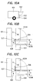
- Figs. 10B and 10C In the lower door 103 of the rear door of the divided type, structures as shown in Figs. 10B and 10C are usually conceivable as mounting structures for hinges which support the lower door 103 pivotably.
- an arm 106 of a hinge 105 is attached to the lower end side of a lower door 103A put in a closed state, and a base 107 supporting the arm 106 pivotably is mounted on a vehicle body 101.
- the arm 106 is mounted on the front surface side (the surface facing the vehicle body 101) of a lower door 103B placed in an open state.
- Fig. 10B for example, an arm 106 of a hinge 105 is attached to the lower end side of a lower door 103A put in a closed state, and a base 107 supporting the arm 106 pivotably is mounted on a vehicle body 101.
- the arm 106 is mounted on the front surface side (the surface facing the vehicle body 101) of a lower door 103B placed in an open state.
- an arm 106 of a hinge 105 is mounted on the front surface side (the surface facing the vehicle body 101) of a lower door 103A placed in a closed state.
- the arm 106 is mounted on the upper surface side of a lower door 103B placed in an open state.
- a large clearance S is required between the upper end of a bumper 104 and the lower end of the lower door 103A placed in the closed state, in order to secure a space for the lower door 103B placed in the open state.
- This lowers the degree of freedom of a design for this portion, and results in poor appearance.
- the position of mounting of the arm 106 is remote from the position of center of gravity G of the lower door 103 in a side view, thus requiring a high mounting strength for the portion where the arm 106 is mounted.
- a wire 111 is connected to one end of the lower door 103.
- the wire 111 may be temporarily placed on the lower door 103 only.
- the wire 111 may be detached from the vehicle body, or may be disconnected from the lower door, or may be broken, as shown in Fig. 11B. As a result, the lower door may fall off, or the luggage 112 may be dropped, injuring an operator.
- the present invention has been accomplished in light of the above-described problems with the earlier technologies. It is an object of the invention to provide an opening and closing apparatus of a vehicle, which does no harm to appearance or loading and unloading work for luggage while ensuring the strength and load bearing properties of a mounting portion.
- a first aspect of the present invention is an opening and closing apparatus of a vehicle, comprising: an opening and closing member for opening and closing an opening portion of a vehicle body; a lower hinge pivotally supported in a lower edge portion of the opening portion for supporting the opening and closing member to be pivotable; and a cover member disposed below the opening and closing member placed in a closed state for covering a pivot support portion of the lower hinge from behind, wherein the lower hinge has a pivoting portion supported to be pivotable about the pivot support portion, the pivoting portion has a bent shape so that when the opening and closing member is in an open state, the pivoting portion straddles the cover member, and the opening and closing member is located rearwardly of the cover member in a longitudinal direction of the vehicle body, and an uppermost site of the pivoting portion is located at a position not higher than an upper surface of the opening and closing member when the opening and closing member is in the open state.
- a second aspect of the present invention is the opening and closing apparatus of a vehicle according to the first aspect, wherein the pivoting portion supports the opening and closing member from a side surface in a vehicle width direction.
- a third aspect of the present invention is the opening and closing apparatus of a vehicle according to the first or second aspect, wherein a position of mounting of the pivoting portion of the lower hinge on the opening and closing member is in proximity to a position of center of gravity of the opening and closing member in a side view.
- a fourth aspect of the present invention is the opening and closing apparatus of a vehicle according to any one of the first to third aspects, wherein a sheet member is provided for covering the upper surface of the opening and closing member and the lower edge portion of the opening portion of the vehicle body when the opening and closing member is in the open state.
- a fifth aspect of the present invention is the opening and closing apparatus of a vehicle according to any one of the first to fourth aspects, wherein a wire having an end mounted on the vehicle body and another end mounted on the opening and closing member is further provided for supporting the upper surface of the opening and closing member in the open state to be nearly horizontal; the lower hinge has a stopper for restraining rotation of the pivoting portion; when load imposed on the opening and closing member in the open state is not greater than a predetermined value, the wire supports the opening and closing member; and when the load is greater than the predetermined value, the stopper restrains the pivoting portion of the lower hinge to support the opening and closing member.
- a sixth aspect of the present invention is the opening and closing apparatus of a vehicle according to the fifth aspect, wherein the stopper is provided at a position close to a rotating shaft portion of the lower hinge, and contacts the pivoting portion to restrain the rotation of the pivoting portion.
- a seventh aspect of the present invention is the opening and closing apparatus of a vehicle according to the fifth or sixth aspect, wherein taken-up means for taking up the wire when the opening and closing member is closed is provided in the vehicle body.
- a space for the opening and closing member in the open state need not be secured between the opening and closing member (lower door) and the cover member (bumper).
- the degree of freedom of design for the rear portion of the vehicle can be increased. Consequently, the opening and closing member and the cover member can be designed to have an integral appearance.
- the pivoting portion (arm) of the hinge does not jut upward. Thus, a large opening portion of the vehicle can be secured.
- the mounting position of the pivoting portion of the hinge is supported from the side surface in the vehicle width direction.
- a structure in which the pivoting portion (arm) of the hinge does not jut upward can be provided.
- the position of mounting of the pivoting portion of the hinge is in proximity to the position of center of gravity of the opening and closing member.
- the mounting strength of the pivoting portion can be ensured.
- the sheet member is provided.
- the sheet member covers the opening and closing member (lower door) and the floor surface of the lower edge portion of the opening portion of the vehicle body.
- the uppermost site of the arm is located at a lower position than the upper surface of the lower door in the open state, namely, below the sheet member.
- the arm does not jut out over the sheet member. Consequently, a large opening portion can be secured for the lower door and, on the lower door in the open state, the horizontal movement of luggage can be facilitated.
- the opening and closing member when greater load than predetermined load is imposed on the opening and closing member (lower door), the opening and closing member is supported by the stopper of the hinge.
- the stopper secondarily supports the opening and closing member, and thus shares the load imposed on the wire.
- cost reduction can be achieved, and downsizing, simplification, and weight reduction of the hinge can also be achieved. Since the hinge is downsized and simplified, moreover, its appearance can also be improved.
- the stopper is provided at a position close to the rotating shaft portion of the hinge.
- the hinge can be downsized.
- the take-up means is of the winding type.
- compact accommodation of the wire can be achieved, and entanglement of the wire with the vehicle body or the opening and closing member can be prevented during the opening and closing of the opening and closing member (lower door).
- combination of the take-up means with the stopper decreases the divided load on the take-up means.
- the take-up means itself can be downsized.
- Fig. 1 is a schematic view showing a rear portion of a vehicle.
- Fig. 2 is a schematic view showing a state in which an upper door and a lower door are opened in the rear portion of the vehicle.
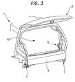
- Fig. 3 is a schematic view showing a state in which the upper door is opened, with some garnishes, a bumper, etc. being removed for illustrating an internal structure.
- Fig. 4 is a schematic view showing a state in which the upper door and the lower door are opened, with some garnishes, bumper, etc. being removed for illustrating the internal structure.
- Figs. 5A and 5B are perspective views of a reel and a hinge according to the present invention.
- Figs. 6A and 6B are views illustrating the actions of the hinge according to the present invention.
- FIG. 7 is an external appearance view, as a side view, showing the arrangement relationship between the hinge and other members according to the present invention.
- Fig. 8 is a view illustrating the arrangement relationship among respective members in a state in which the upper door and the lower door are opened in the rear portion of the vehicle.
- Fig. 9 is a side view, in perspective, showing the arrangement relationship between the hinge and other members according to the present invention.
- a rear portion of a vehicle body 1 has a structure in which an upper door 2 opens upward, and a lower door 3 (opening and closing member) opens downward, in a separated manner.
- the present invention can be configured, because of the use of an opening and closing apparatus of a vehicle according to the invention, such that the lower door 3 and a bumper 4 below the lower door 3 have an integral appearance.
- the opening and closing apparatus of a vehicle is equipped with the lower door 3 openably and closably mounted on the vehicle body 1 via a hinge 7 (arm 8 (pivoting portion), base 9 (pivot support portion)), and the bumper 4 (cover member) disposed below the lower door 3 in a closed state for covering the base 9 of the hinge 7 from behind.
- the hinge 7 has the base 9 mounted on the vehicle body 1, and the arm 8 supported by the base 9 to be pivotable in a predetermined range.
- the lower door 3 is supported by the arm 8 in each of its opposite side end portions.
- a wire 6 having one end attached to the vehicle body 1 and the other end attached to the lower door 3 is also provided.
- the wire 6 supports the upper surface of the lower door 3 nearly horizontally.
- a reel 5 (take-up means) for taking up the wire 6 is disposed in the vehicle body 1.
- the wire 6 is automatically taken into the reel 5, and accommodated in the interior of the reel 5.
- the hinge 7 has a stopper 91 for restraining the rotation of the arm 8 to restrict the opening of the lower door 3.
- a stopper 91 for restraining the rotation of the arm 8 to restrict the opening of the lower door 3.
- Fig. 5A is a perspective view of the reel 5
- Fig. 5B is a perspective view of the hinge 7 when the lower door 3 is in an open state
- Figs. 6A, 6B are views illustrating the actions of the hinge.
- the hinge 7 consists of the arm 8 and the base 9.
- the arm 8 consists of a support portion 81 for supporting the opposite side end portion of the lower door 3, a bending portion 82 bent (curved) toward the upper side of the vehicle body, and a restraint portion 83 supported by the base 9 and making a rotating motion restrained by the stopper 91.
- the bending portion 82 is provided to have a bent portion between the pivot support portion journaled at the base 9 and the support portion 81.
- the bending portion 82 has such a shape that when the lower door 3 is open, the bending portion 82 straddles the bumper 4, and the lower door 3 is disposed behind the bumper 4 in the longitudinal direction of the vehicle body.
- the arm 8 is mounted on a side surface in the vehicle width direction of the lower door 3 such that the uppermost site of the hinge 7, namely, the uppermost site 84 of the arm 8, is located at a lower position than the upper surface of the lower door 3 placed in the open state (see Fig. 5B).
- the base 9 comprises the stopper 91 for restraining the rotating motion of the arm 8, namely, for restricting the opening of the lower door 3, a rotating shaft portion 92 for supporting the arm 9 pivotably, a holding portion 93 for holding the stopper 91 and the rotating shaft portion 92, and a fixed portion 94 fixed to the vehicle body 1.
- the holding portion 93 is provided with a bend 95 in order to downsize the base 9 and maintain its strength.
- an arm 8A represents the position of the arm when the lower door 3 is closed
- an arm 8B represents the position of the arm when the lower door 3 is fully open
- an arm 8C represents an open state during ordinary use (indicating a position moved toward the closed state by a predetermined angle with respect the fully open state).
- the arm 8 supporting the lower door 3 takes the position of the arm 8A.
- the restraint portion 83 and the bending portion 82 of the arm 8 are accommodated in the region of the holding portion 93 of the base 9, and the support portion 81 is located above the holding portion 93 nearly vertically. That is, when the lower door 3 is closed, the restraint portion 83 and the bending portion 82 of the arm 8 are accommodated in the interior of the bumper 4 covering the base 9.
- the lower door 3 supported by the support portion 81 is located above the bumper 4 to have an appearance nearly integral with the bumper 4, as shown in Fig. 1.
- the arm 8 assumes the position of the arm 8C.
- the bending portion 82 of the arm 8 is located to be above the holding portion 93 of the base 9 and rearward in the vehicle (rightward in Fig. 6B).
- the support portion 81 is located further rearwardly of the bending portion 82 and nearly horizontally. That is, when the lower door 3 is open, the bending portion 82 of the arm 8 straddles the bumper 4, and the lower door 3 supported by the support portion 81 is located rearwardly of the bumper 4 in the longitudinal direction of the vehicle body.
- Figs. 7 and 9 are side views of the vehicle shown in Figs. 2 and 4, clarifying the arrangement of the respective members.
- the lower door 3 in the open state (see the lower door 3A) straddles the bumper 4 and opens to the rear of the vehicle, because of the shape of the arm 8 of the hinge 7.
- a space for accommodation of the lower door 3 in the open state need not be ensured between the bumper 4 and the lower door 3.
- the clearance "s" between the upper end of the bumper 4 and the lower end of the lower door 3B is minimal, so that the lower door 3 and the bumper 4 can together form an integral appearance, and increase the degree of freedom of design.
- Such a configuration makes it possible to ensure the strength of a portion where load is concentrated, concretely, the mounting portion of the arm 8 or the portion surrounding the fixing point 34 of the wire 6.
- a sheet member 33 covers the lower door 3 and the floor surface of the vehicle body 1 in order to facilitate the horizontal movement of luggage.
- the uppermost site 84 of the arm 8 is located at a lower position than the upper surface of the lower door 3 in the open state, namely, below the sheet member 33.
- the arm 8 does not jut out over the sheet member 33. Consequently, a large opening portion can be secured for the lower door 3.
- Fig. 8 corresponds to a side view of the vehicle shown in Fig. 4, designed to elucidate the arrangement of the respective members.
- load has a predetermined value or lower
- the upper surface of the lower door 3 is nearly horizontal, and the own weight of the lower door 3 and luggage with up to a predetermined load are supported by the wire 6 fixed to the fixing point 34 in the upper end portion of the lower door 3.
- the amount of the wire 6 paid out is regulated by a stop 54, a clearance t is formed between the restraint portion 83 of the arm 8 and the stopper 91, and only the wire 6 supports the lower door 3, although details will be offered in Figs. 5A, 5B and 6A, 6B.
- the sheet member 33 covers the lower door 3 and the floor surface of the vehicle body 1 in order to facilitate the horizontal movement of luggage.
- the reel 5 includes a reel body 51 for taking up the wire 6, a bracket 52 fixed to the vehicle body 1 for holding the reel body 51, and a guide 53 fixed to the bracket 52 for guiding along a paying-out direction the wire 6 paid out from the lower side of the reel body 51.
- the wire 6 when the wire 6 is to be taken up, namely, when the lower door 3 is to be closed, the wire 6 is automatically taken into the interior of the reel body 51 by the force of a spring member disposed within the reel body 51.
- the wire 6 is to be paid out, namely, when the lower door 3 is to be opened, the wire 6 is paid out of the reel body 51 by the own weight of the lower door 3.
- the stop 54 mounted on the wire 6 is restrained by an end portion of the guide 53, so that the lower door 3 in the open state is supported by the wire 6. If a heavier load than the predetermined load is imposed on the lower door 3, the stop 54 mounted on the wire 6 is displaced to increase the amount of paying-out of the wire 6 slightly, thereby rendering the lower door 3 fully open. As a result, the lower door 3 in the fully open state is supported by the wire 6 and the stopper 91 (to be described later). Here, the stop 54 functions to regulate the amount of the wire 6 paid out.
- the base 9 is provided with the stopper 91 at a position close to the rotating shaft portion 92 supporting the arm 8. To downsize the base 9 and maintain its strength, a bend 96 is provided in the stopper 91, as the bend 95 is provided in the holding portion 93.
- the arm 8 of the hinge 7 which supports the lower door 3 to be pivotable, takes the position of the arm 8A.
- Fig. 6B when the lower door 3 is opened (see Figs. 2 and 4), the arm 8 of the hinge 7 takes the position of the arm 8C.
- the lower door 3 is fixed at the fixing point 34 for the wire 6, and the opening of the lower door 3 is restricted by the amount of paying-out of the wire 6 controlled by the stop 54.
- the arm is located at a position moved toward the closed state by a predetermined angle with respect the fully open state, so that the slight clearance t is formed between the stopper 91 and the restraint portion 83 of the arm 8C. Consequently, when luggage with a predetermined load or less within an expected range is loaded or unloaded, the lower door 3 is supported only by the wire 6, even if load is imposed on the lower door 3.
- the stop 54 on the wire 6 is displaced, if load is imposed on the lower door 3.
- the arm 8 is rotated to the position of the arm 8B (fully open state) to bring the restraint portion 83 into contact with the stopper 91.
- the lower door 3 is supported by the wire 3 and the stopper 91.
- the stopper 91 for restraining the rotation of the arm 8 is provided in the base 9 of the hinge 7.
- the stopper 91 supports the arm 8, i.e., the lower door 3, before the wire 6 breaks.
- the supporting force of the stopper 91 works secondarily, in addition to the supporting force of the wire 6, thus preventing the fall of the lower door 3 or the luggage.
- the stopper 91 shares the load imposed on the wire 6, thus obviating the need to impart more strength than required to the wire 6 or the hinge 7.
- the stop for the wire is described as a means of restraining the paying-out of the wire.
- the wire may be directly welded and fixed to the vehicle body, the take-up means, or the central shaft of the take-up means.
- the stop may be mounted on the wire by caulking, or the end of the wire may be folded back, and a cylindrical stopper may be provided in a hole formed by the folded-back portion.
Landscapes
- Engineering & Computer Science (AREA)
- Mechanical Engineering (AREA)
- Body Structure For Vehicles (AREA)
- Superstructure Of Vehicle (AREA)
Abstract
an opening and closing member (3) for opening and closing an opening portion (10) of a vehicle body (1) ; a lower hinge (7) for pivotably supporting the opening and closing member (3) from below; and a cover member (4) disposed below the opening and closing member (3) placed in a closed state for covering a pivot support portion (9) of the lower hinge (7) from behind, wherein when the opening and closing member (3) is in an open state, a pivoting portion (8) pivotably supported by the pivot support portion (9) straddles the cover member (4), the opening and clos ing member (3) is located rearwardly of the cover member (4), and an uppermost site (84) of the pivoting portion (8) is located at a position not higher than an upper surface of the opening and closing member (3).
Description
- This invention relates to an opening and closing apparatus of a vehicle. This apparatus is preferred, for example, as an opening and closing apparatus for a door in a rear portion of a vehicle, which is divided into an upper door and a lower door opened upward and downward in a separated manner.
- In a vehicle such as an RV (recreational vehicle), an opening portion of a rear door is rendered large so that large luggage can be loaded, and the rear door is itself large. In opening the rear door, therefore, a wide space is required behind the vehicle in order to ensure an opening and closing range. To avoid such a space problem, a rear portion of a
vehicle 101 is divided into anupper door 102 and alower door 103 which are opened upward and downward in a separated manner, as shown in Fig. 10A. Since theupper door 102 and thelower door 103 are opened upward and downward in a separated manner, the opening and closing range of theupper door 102 and thelower door 103 can be rendered narrow, thus decreasing a necessary space behind the vehicle. -
Japanese Utility Model Application Laid-Open No. 1992-114814 Japanese Utility Model Publication No. 1994-5488 - In the
lower door 103 of the rear door of the divided type, structures as shown in Figs. 10B and 10C are usually conceivable as mounting structures for hinges which support thelower door 103 pivotably. In the mounting structure of Fig. 10B, for example, anarm 106 of ahinge 105 is attached to the lower end side of alower door 103A put in a closed state, and abase 107 supporting thearm 106 pivotably is mounted on avehicle body 101. In other words, thearm 106 is mounted on the front surface side (the surface facing the vehicle body 101) of alower door 103B placed in an open state. In the mounting structure of Fig. 10C, on the other hand, anarm 106 of ahinge 105 is mounted on the front surface side (the surface facing the vehicle body 101) of alower door 103A placed in a closed state. In other words, thearm 106 is mounted on the upper surface side of alower door 103B placed in an open state. - In each of the above-mentioned hinge mounting structures, a large clearance S is required between the upper end of a
bumper 104 and the lower end of thelower door 103A placed in the closed state, in order to secure a space for thelower door 103B placed in the open state. This lowers the degree of freedom of a design for this portion, and results in poor appearance. Moreover, the position of mounting of thearm 106 is remote from the position of center of gravity G of thelower door 103 in a side view, thus requiring a high mounting strength for the portion where thearm 106 is mounted. - Furthermore, as shown in Fig. 11A, if a rear portion of a
vehicle 101 is divided into anupper door 102 and alower door 103 which are opened upward and downward in a separated manner, awire 111 is connected to one end of thelower door 103. In the open state, only thewire 111 keeps the open state and supports thelower door 103. Ifluggage 112 is loaded and unloaded with the use of such a structure, theluggage 112 may be temporarily placed on thelower door 103 only. In this case, under an unexpectedly heavy load, thewire 111 may be detached from the vehicle body, or may be disconnected from the lower door, or may be broken, as shown in Fig. 11B. As a result, the lower door may fall off, or theluggage 112 may be dropped, injuring an operator. - The present invention has been accomplished in light of the above-described problems with the earlier technologies. It is an object of the invention to provide an opening and closing apparatus of a vehicle, which does no harm to appearance or loading and unloading work for luggage while ensuring the strength and load bearing properties of a mounting portion.
- This object can be achieved by the features specified in the claims. Particularly, a
first aspect of the present invention is an opening and closing apparatus of a vehicle, comprising: an opening and closing member for opening and closing an opening portion of a vehicle body; a lower hinge pivotally supported in a lower edge portion of the opening portion for supporting the opening and closing member to be pivotable; and a cover member disposed below the opening and closing member placed in a closed state for covering a pivot support portion of the lower hinge from behind, wherein the lower hinge has a pivoting portion supported to be pivotable about the pivot support portion, the pivoting portion has a bent shape so that when the opening and closing member is in an open state, the pivoting portion straddles the cover member, and the opening and closing member is located rearwardly of the cover member in a longitudinal direction of the vehicle body, and an uppermost site of the pivoting portion is located at a position not higher than an upper surface of the opening and closing member when the opening and closing member is in the open state. - A second aspect of the present invention is the opening and closing apparatus of a vehicle according to the first aspect, wherein the pivoting portion supports the opening and closing member from a side surface in a vehicle width direction.
- A third aspect of the present invention is the opening and closing apparatus of a vehicle according to the first or second aspect, wherein a position of mounting of the pivoting portion of the lower hinge on the opening and closing member is in proximity to a position of center of gravity of the opening and closing member in a side view.
- A fourth aspect of the present invention is the opening and closing apparatus of a vehicle according to any one of the first to third aspects,
wherein a sheet member is provided for covering the upper surface of the opening and closing member and the lower edge portion of the opening portion of the vehicle body when the opening and closing member is in the open state. - A fifth aspect of the present invention is the opening and closing apparatus of a vehicle according to any one of the first to fourth aspects,
wherein a wire having an end mounted on the vehicle body and another end mounted on the opening and closing member is further provided for supporting the upper surface of the opening and closing member in the open state to be nearly horizontal; the lower hinge has a stopper for restraining rotation of the pivoting portion; when load imposed on the opening and closing member in the open state is not greater than a predetermined value, the wire supports the opening and closing member; and when the load is greater than the predetermined value, the stopper restrains the pivoting portion of the lower hinge to support the opening and closing member. - A sixth aspect of the present invention is the opening and closing apparatus of a vehicle according to the fifth aspect, wherein the stopper is provided at a position close to a rotating shaft portion of the lower hinge, and contacts the pivoting portion to restrain the rotation of the pivoting portion.
- A seventh aspect of the present invention is the opening and closing apparatus of a vehicle according to the fifth or sixth aspect, wherein taken-up means for taking up the wire when the opening and closing member is closed is provided in the vehicle body.
- According to the first aspect of the invention, a space for the opening and closing member in the open state need not be secured between the opening and closing member (lower door) and the cover member (bumper). Thus, the degree of freedom of design for the rear portion of the vehicle can be increased. Consequently, the opening and closing member and the cover member can be designed to have an integral appearance. Furthermore, while the opening and closing member is open, the pivoting portion (arm) of the hinge does not jut upward. Thus, a large opening portion of the vehicle can be secured.
- According to the second aspect of the invention, the mounting position of the pivoting portion of the hinge is supported from the side surface in the vehicle width direction. Thus, a structure in which the pivoting portion (arm) of the hinge does not jut upward can be provided.
- According to the third aspect of the invention, the position of mounting of the pivoting portion of the hinge is in proximity to the position of center of gravity of the opening and closing member. Thus, the mounting strength of the pivoting portion can be ensured.
- According to the fourth aspect of the invention, the sheet member is provided. Thus, the sheet member covers the opening and closing member (lower door) and the floor surface of the lower edge portion of the opening portion of the vehicle body. Thus, the uppermost site of the arm is located at a lower position than the upper surface of the lower door in the open state, namely, below the sheet member. Thus, the arm does not jut out over the sheet member. Consequently, a large opening portion can be secured for the lower door and, on the lower door in the open state, the horizontal movement of luggage can be facilitated.
- According to the fifth aspect of the invention, when greater load than predetermined load is imposed on the opening and closing member (lower door), the opening and closing member is supported by the stopper of the hinge. Thus, the wire does not break, and the fall of the opening and closing member or the luggage can be prevented. Moreover, the stopper secondarily supports the opening and closing member, and thus shares the load imposed on the wire. Thus, it is not necessary to render the wire thicker than required, and there is no need to impart more strength than required to the hinge. As a result, cost reduction can be achieved, and downsizing, simplification, and weight reduction of the hinge can also be achieved. Since the hinge is downsized and simplified, moreover, its appearance can also be improved.
- According to the sixth aspect of the invention, the stopper is provided at a position close to the rotating shaft portion of the hinge. Thus, the hinge can be downsized.
- According to the seventh aspect of the invention, the take-up means is of the winding type. Thus, compact accommodation of the wire can be achieved, and entanglement of the wire with the vehicle body or the opening and closing member can be prevented during the opening and closing of the opening and closing member (lower door). Furthermore, combination of the take-up means with the stopper decreases the divided load on the take-up means. Thus, the take-up means itself can be downsized.
The present invention will become more fully understood from the detailed description given hereinbelow and the accompanying drawings which are given by way of illustration only, and thus are not limitative of the present invention, and wherein: - Fig. 1 is a schematic view showing a rear portion of a vehicle;
- Fig. 2 is a schematic view showing a state in which an upper door and a lower door are opened in the rear portion of the vehicle;
- Fig. 3 is a schematic view showing a state in which the upper door is opened in the rear portion of the vehicle, with some garnishes, etc. being removed for illustrating an internal structure;
- Fig. 4 is a schematic view showing a state in which the upper door and the lower door are opened in the rear portion of the vehicle, with some garnishes, bumper, etc. being removed for illustrating the internal structure;
- Figs. 5A and 5B are perspective views of a reel and a hinge according to the present invention;
- Figs. 6A and 6B are views illustrating the actions of the hinge according to the present invention;
- Fig. 7 is an external appearance view, as a side view, showing the arrangement relationship between the hinge and other members according to the present invention;
- Fig. 8 is a view illustrating the arrangement relationship among respective members in a state in which the upper door and the lower door are opened in the rear portion of the vehicle;
- Fig. 9 is a side view, in perspective, showing the arrangement relationship between the hinge and other members according to the present invention;
- Figs. 10A to 10C are views illustrating the problems of a conventional opening and closing apparatus of a vehicle; and
- Figs. 11A and 11B are views illustrating the problems of a conventional opening and closing apparatus of a vehicle.
- An opening and closing apparatus of a vehicle according to the present invention will be described in detail with reference to Figs. 1 to 9.
- Fig. 1 is a schematic view showing a rear portion of a vehicle. Fig. 2 is a schematic view showing a state in which an upper door and a lower door are opened in the rear portion of the vehicle. Fig. 3 is a schematic view showing a state in which the upper door is opened, with some garnishes, a bumper, etc. being removed for illustrating an internal structure. Fig. 4 is a schematic view showing a state in which the upper door and the lower door are opened, with some garnishes, bumper, etc. being removed for illustrating the internal structure. Figs. 5A and 5B are perspective views of a reel and a hinge according to the present invention. Figs. 6A and 6B are views illustrating the actions of the hinge according to the present invention. Fig. 7 is an external appearance view, as a side view, showing the arrangement relationship between the hinge and other members according to the present invention. Fig. 8 is a view illustrating the arrangement relationship among respective members in a state in which the upper door and the lower door are opened in the rear portion of the vehicle. Fig. 9 is a side view, in perspective, showing the arrangement relationship between the hinge and other members according to the present invention.
- As shown in Figs. 1 to 4, a rear portion of a
vehicle body 1 has a structure in which anupper door 2 opens upward, and a lower door 3 (opening and closing member) opens downward, in a separated manner. The present invention can be configured, because of the use of an opening and closing apparatus of a vehicle according to the invention, such that thelower door 3 and abumper 4 below thelower door 3 have an integral appearance. - The opening and closing apparatus of a vehicle according to the present invention is equipped with the
lower door 3 openably and closably mounted on thevehicle body 1 via a hinge 7 (arm 8 (pivoting portion), base 9 (pivot support portion)), and the bumper 4 (cover member) disposed below thelower door 3 in a closed state for covering thebase 9 of thehinge 7 from behind. Thehinge 7 has thebase 9 mounted on thevehicle body 1, and thearm 8 supported by thebase 9 to be pivotable in a predetermined range. Thelower door 3 is supported by thearm 8 in each of its opposite side end portions. - A
wire 6 having one end attached to thevehicle body 1 and the other end attached to thelower door 3 is also provided. When thelower door 3 is brought to an open state, thewire 6 supports the upper surface of thelower door 3 nearly horizontally. A reel 5 (take-up means) for taking up thewire 6 is disposed in thevehicle body 1. When thelower door 3 is to be brought to a closed state, thewire 6 is automatically taken into thereel 5, and accommodated in the interior of thereel 5. By so having thewire 6 of the take-up type, the accommodation of thewire 6 can be performed compactly, and thewire 6 can be prevented from being entangled with the vehicle body or thelower door 3 when thelower door 3 is opened or closed. - The
hinge 7 has astopper 91 for restraining the rotation of thearm 8 to restrict the opening of thelower door 3. In thelower door 3 in the open state, if a load of a predetermined value or lower is imposed on thelower door 3, the load is supported by thewire 6 alone. If a load of a higher value than the predetermined value is imposed on thelower door 3, the load is supported by thewire 6 and thestopper 91. The details of these features will be described later. - The configurations of the
reel 5 and thehinge 7 will be described in detail using Figs. 5A, 5B and Figs. 6A, 6B. Fig. 5A is a perspective view of thereel 5, and Fig. 5B is a perspective view of thehinge 7 when thelower door 3 is in an open state. Figs. 6A, 6B are views illustrating the actions of the hinge. - As stated earlier, the
hinge 7 consists of thearm 8 and thebase 9. Thearm 8 consists of asupport portion 81 for supporting the opposite side end portion of thelower door 3, a bendingportion 82 bent (curved) toward the upper side of the vehicle body, and arestraint portion 83 supported by thebase 9 and making a rotating motion restrained by thestopper 91.
The bendingportion 82 is provided to have a bent portion between the pivot support portion journaled at thebase 9 and thesupport portion 81. The bendingportion 82 has such a shape that when thelower door 3 is open, the bendingportion 82 straddles thebumper 4, and thelower door 3 is disposed behind thebumper 4 in the longitudinal direction of the vehicle body. Thearm 8 is mounted on a side surface in the vehicle width direction of thelower door 3 such that the uppermost site of thehinge 7, namely, theuppermost site 84 of thearm 8, is located at a lower position than the upper surface of thelower door 3 placed in the open state (see Fig. 5B). - The
base 9 comprises thestopper 91 for restraining the rotating motion of thearm 8, namely, for restricting the opening of thelower door 3, arotating shaft portion 92 for supporting thearm 9 pivotably, a holdingportion 93 for holding thestopper 91 and therotating shaft portion 92, and a fixedportion 94 fixed to thevehicle body 1. In thebase 9, the holdingportion 93 is provided with abend 95 in order to downsize thebase 9 and maintain its strength. - Next, the actions of the
hinge 7 for supporting thelower door 3 to be openable and closable, concretely, the actions of thearm 8, will be described with reference to Figs. 6A and 6B. In Fig. 6A, anarm 8A represents the position of the arm when thelower door 3 is closed, and anarm 8B represents the position of the arm when thelower door 3 is fully open. In Fig. 6B, anarm 8C represents an open state during ordinary use (indicating a position moved toward the closed state by a predetermined angle with respect the fully open state). - As shown in Fig. 6A, when the
lower door 3 is closed, thearm 8 supporting thelower door 3 takes the position of thearm 8A. At this time, therestraint portion 83 and the bendingportion 82 of thearm 8 are accommodated in the region of the holdingportion 93 of thebase 9, and thesupport portion 81 is located above the holdingportion 93 nearly vertically. That is, when thelower door 3 is closed, therestraint portion 83 and the bendingportion 82 of thearm 8 are accommodated in the interior of thebumper 4 covering thebase 9. Thelower door 3 supported by thesupport portion 81 is located above thebumper 4 to have an appearance nearly integral with thebumper 4, as shown in Fig. 1. - As shown in Fig. 6B, when the
lower door 3 is open, thearm 8 assumes the position of thearm 8C. Here, the bendingportion 82 of thearm 8 is located to be above the holdingportion 93 of thebase 9 and rearward in the vehicle (rightward in Fig. 6B). Thesupport portion 81 is located further rearwardly of the bendingportion 82 and nearly horizontally. That is, when thelower door 3 is open, the bendingportion 82 of thearm 8 straddles thebumper 4, and thelower door 3 supported by thesupport portion 81 is located rearwardly of thebumper 4 in the longitudinal direction of the vehicle body. - Next, the arrangement relationship between the
hinge 7 and other members will be described using Figs. 7 and 9. Figs. 7 and 9 are side views of the vehicle shown in Figs. 2 and 4, clarifying the arrangement of the respective members. - As shown in Figs. 7 and 9, the
lower door 3 in the open state (see thelower door 3A) straddles thebumper 4 and opens to the rear of the vehicle, because of the shape of thearm 8 of thehinge 7. Thus, a space for accommodation of thelower door 3 in the open state need not be ensured between thebumper 4 and thelower door 3. With thelower door 3 in the closed state (see thelower door 3B), the clearance "s" between the upper end of thebumper 4 and the lower end of thelower door 3B is minimal, so that thelower door 3 and thebumper 4 can together form an integral appearance, and increase the degree of freedom of design. - As shown in Figs. 7 and 9, when the
lower door 3 is brought to the open state (see thelower door 3A), the upper surface of thelower door 3 supported by the hinge 7 (arm 8, base 9) becomes nearly horizontal, and thewire 6 is paid out from thereel 5. Thus, thelower door 3 is supported by thewire 6 fixed to afixing point 34 in an upper end portion of thelower door 3. The fixingpoint 34 for thewire 6 on thelower door 3 is located in proximity to a mounting portion of thearm 8 on thelower door 3. Furthermore, the position of mounting of thearm 8 on thelower door 3 is also in the neighborhood of the position of center of gravity G of thelower door 3 in the side view. Such a configuration makes it possible to ensure the strength of a portion where load is concentrated, concretely, the mounting portion of thearm 8 or the portion surrounding the fixingpoint 34 of thewire 6. With thelower door 3 in the open state, asheet member 33 covers thelower door 3 and the floor surface of thevehicle body 1 in order to facilitate the horizontal movement of luggage. Here, theuppermost site 84 of thearm 8 is located at a lower position than the upper surface of thelower door 3 in the open state, namely, below thesheet member 33. Thus, thearm 8 does not jut out over thesheet member 33. Consequently, a large opening portion can be secured for thelower door 3. - Next, the configuration of the
stopper 91, which is provided in thehinge 7 and restrains the rotation of thearm 8 to restrict the opening of thelower door 3, will be described in detail with reference to Figs. 5A, 5B, 6A, 6B and 8. Fig. 8 corresponds to a side view of the vehicle shown in Fig. 4, designed to elucidate the arrangement of the respective members.
As shown in Fig. 8, when thelower door 3 is brought to an open state under ordinary conditions (where load has a predetermined value or lower), the upper surface of thelower door 3 is nearly horizontal, and the own weight of thelower door 3 and luggage with up to a predetermined load are supported by thewire 6 fixed to thefixing point 34 in the upper end portion of thelower door 3. Here, the amount of thewire 6 paid out is regulated by astop 54, a clearance t is formed between therestraint portion 83 of thearm 8 and thestopper 91, and only thewire 6 supports thelower door 3, although details will be offered in Figs. 5A, 5B and 6A, 6B. With thelower door 3 in the open state, thesheet member 33 covers thelower door 3 and the floor surface of thevehicle body 1 in order to facilitate the horizontal movement of luggage. - As shown in Fig. 5A, the
reel 5 includes areel body 51 for taking up thewire 6, abracket 52 fixed to thevehicle body 1 for holding thereel body 51, and aguide 53 fixed to thebracket 52 for guiding along a paying-out direction thewire 6 paid out from the lower side of thereel body 51. In thereel 5, when thewire 6 is to be taken up, namely, when thelower door 3 is to be closed, thewire 6 is automatically taken into the interior of thereel body 51 by the force of a spring member disposed within thereel body 51. When thewire 6 is to be paid out, namely, when thelower door 3 is to be opened, thewire 6 is paid out of thereel body 51 by the own weight of thelower door 3. When the upper surface of thelower door 3 has become nearly horizontal, thestop 54 mounted on thewire 6 is restrained by an end portion of theguide 53, so that thelower door 3 in the open state is supported by thewire 6. If a heavier load than the predetermined load is imposed on thelower door 3, thestop 54 mounted on thewire 6 is displaced to increase the amount of paying-out of thewire 6 slightly, thereby rendering thelower door 3 fully open. As a result, thelower door 3 in the fully open state is supported by thewire 6 and the stopper 91 (to be described later). Here, thestop 54 functions to regulate the amount of thewire 6 paid out. - The
base 9 is provided with thestopper 91 at a position close to therotating shaft portion 92 supporting thearm 8. To downsize thebase 9 and maintain its strength, abend 96 is provided in thestopper 91, as thebend 95 is provided in the holdingportion 93. - As shown in Fig. 6A, when the
lower door 3 is closed (see Figs. 1 and 3), thearm 8 of thehinge 7, which supports thelower door 3 to be pivotable, takes the position of thearm 8A. As shown in Fig. 6B, when thelower door 3 is opened (see Figs. 2 and 4), thearm 8 of thehinge 7 takes the position of thearm 8C. At this time, thelower door 3 is fixed at thefixing point 34 for thewire 6, and the opening of thelower door 3 is restricted by the amount of paying-out of thewire 6 controlled by thestop 54. Thus, the arm is located at a position moved toward the closed state by a predetermined angle with respect the fully open state, so that the slight clearance t is formed between thestopper 91 and therestraint portion 83 of thearm 8C. Consequently, when luggage with a predetermined load or less within an expected range is loaded or unloaded, thelower door 3 is supported only by thewire 6, even if load is imposed on thelower door 3. - When luggage heavier than the predetermined load beyond the expected range is loaded or unloaded, the
stop 54 on thewire 6 is displaced, if load is imposed on thelower door 3. As shown in Fig. 6A, thearm 8 is rotated to the position of thearm 8B (fully open state) to bring therestraint portion 83 into contact with thestopper 91. Thus, thelower door 3 is supported by thewire 3 and thestopper 91. - In the opening and closing apparatus according to the present invention, as described above, the
stopper 91 for restraining the rotation of thearm 8 is provided in thebase 9 of thehinge 7. Thus, even if head load is imposed on thelower door 3, thestopper 91 supports thearm 8, i.e., thelower door 3, before thewire 6 breaks. As noted here, upon application of great load, the supporting force of thestopper 91 works secondarily, in addition to the supporting force of thewire 6, thus preventing the fall of thelower door 3 or the luggage. Further, thestopper 91 shares the load imposed on thewire 6, thus obviating the need to impart more strength than required to thewire 6 or thehinge 7. As a result, cost reduction can be achieved for the members, and downsizing, simplification, and weight reduction can also be achieved for the members. Their appearances can also be improved.
The invention thus described, it will be obvious that the same may be varied in many ways. For example, the provision of the stop for the wire is described as a means of restraining the paying-out of the wire. However, this is not limitative, and the wire may be directly welded and fixed to the vehicle body, the take-up means, or the central shaft of the take-up means. Alternatively, the stop may be mounted on the wire by caulking, or the end of the wire may be folded back, and a cylindrical stopper may be provided in a hole formed by the folded-back portion. Such variations are not to be regarded as a departure from the spirit and scope of the invention, and all such modifications as would be obvious to one skilled in the art are intended to be included within the scope of the following claims.
Claims (7)
- An opening and closing apparatus of a vehicle, comprising:an opening and closing member (3) for opening and closing an opening portion (10) of a vehicle body (1);a lower hinge (7) pivotally supported in a lower edge portion of the opening portion (10) for supporting the opening and closing member (3) to be pivotable; anda cover member (4) disposed below the opening and closing member (3) placed in a closed state for covering a pivot support portion (9) of the lower hinge (7) from behind,wherein the lower hinge (7) has a pivoting portion (8) supported to be pivotable about the pivot support portion (9),the pivoting portion (8) has a bent shape so that when the opening and closing member (3) is in an open state, the pivoting portion (8) straddles the cover member (4), and the opening and closing member (3) is located rearwardly of the cover member (4) in a longitudinal direction of the vehicle body (1), andan uppermost site (84) of the pivoting portion (8) is located at a position not higher than an upper surface of the opening and closing member (3) when the opening and closing member (3) is in the open state.
- The opening and closing apparatus of a vehicle according to claim 1, characterized in that the pivoting portion (8) supports the opening and closing member (3) from a side surface in a vehicle width direction.
- The opening and closing apparatus of a vehicle according to claim 1 or 2, characterized in that a position of mounting of the pivoting portion (8) of the lower hinge (7) on the opening and closing member (3) is in proximity to a position of center of gravity (G) of the opening and closing member (3) in a side view.
- The opening and closing apparatus of a vehicle according to any one of claims 1 to 3, characterized in that a sheet member (33) is provided for covering the upper surface of the opening and closing member (3) and the lower edge portion of the opening portion (10) of the vehicle body (1) when the opening and closing member (3) is in the open state.
- The opening and closing apparatus of a vehicle according to any one of claims 1 to 4, characterized in that
a wire (6) having an end mounted on the vehicle body (1) and another end mounted on the opening and closing member (3) is further provided for supporting the upper surface of the opening and closing member (3) in the open state to be nearly horizontal,
the lower hinge (7) has a stopper (91) for restraining rotation of the pivoting portion (8),
when load imposed on the opening and closing member (3) in the open state is not greater than a predetermined value, the wire (6) supports the opening and closing member (3), and
when the load is greater than the predetermined value, the stopper (91) restrains the pivoting portion (8) of the lower hinge (7) to support the opening and closing member (3). - The opening and closing apparatus of a vehicle according to claim 5, characterized in that the stopper (91)
is provided at a position close to a rotating shaft portion (92) of the lower hinge (7), and
contacts the pivoting portion (8, 83) to restrain the rotation of the pivoting portion. - The opening and closing apparatus of a vehicle according to claim 5 or 6, characterized in that
taken-up means (5) for taking up the wire (6) when the opening and closing member (3) is closed is provided in the vehicle body (1).
Applications Claiming Priority (2)
| Application Number | Priority Date | Filing Date | Title |
|---|---|---|---|
| JP2005266369A JP4742765B2 (en) | 2005-09-14 | 2005-09-14 | Vehicle opening / closing device |
| JP2005266367A JP4654855B2 (en) | 2005-09-14 | 2005-09-14 | Vehicle opening / closing device |
Publications (3)
| Publication Number | Publication Date |
|---|---|
| EP1764246A2 true EP1764246A2 (en) | 2007-03-21 |
| EP1764246A3 EP1764246A3 (en) | 2009-12-09 |
| EP1764246B1 EP1764246B1 (en) | 2014-07-30 |
Family
ID=37547547
Family Applications (1)
| Application Number | Title | Priority Date | Filing Date |
|---|---|---|---|
| EP06018971.9A Ceased EP1764246B1 (en) | 2005-09-14 | 2006-09-11 | Opening and closing apparatus of vehicle |
Country Status (2)
| Country | Link |
|---|---|
| US (1) | US7401832B2 (en) |
| EP (1) | EP1764246B1 (en) |
Cited By (1)
| Publication number | Priority date | Publication date | Assignee | Title |
|---|---|---|---|---|
| FR2923778A1 (en) * | 2007-11-15 | 2009-05-22 | Peugeot Citroen Automobiles Sa | Motor vehicle, has rear tailgate moved with respect to loading opening between raised and lowered positions, and connection unit connecting rear tailgate to rear bumper beam, where unit guides tailgate between raised and lowered positions |
Families Citing this family (18)
| Publication number | Priority date | Publication date | Assignee | Title |
|---|---|---|---|---|
| FR2907716B1 (en) * | 2006-10-27 | 2009-02-06 | Plastic Omnium Cie | REAR MODULE FOR REPORTING ON A MOTOR VEHICLE |
| DE102006051645A1 (en) * | 2006-11-02 | 2008-05-08 | Bayerische Motoren Werke Ag | Motor vehicle with a trunk |
| US20090021039A1 (en) * | 2007-07-16 | 2009-01-22 | Quigley Douglas J | Vehicle gate assembly with cargo tray |
| US20090051195A1 (en) * | 2007-08-24 | 2009-02-26 | Ford Global Technologies, Llc | Cargo access and retention system for a passenger vehicle |
| FR2920462B1 (en) * | 2007-09-03 | 2012-07-06 | Plastic Omnium Cie | REAR OPENER, OPENING ASSEMBLY, MOTOR VEHICLE INCLUDING THE SAME OR THIS ASSEMBLY AND ROOF BAR OF THIS VEHICLE |
| US8020912B2 (en) * | 2009-04-21 | 2011-09-20 | Ford Global Technologies, Llc | Rear closure assembly for a passenger vehicle |
| US8109553B2 (en) * | 2009-09-09 | 2012-02-07 | Zielinsky Cary R | Multi-position tailgate retaining and counterbalancing apparatus and method |
| GB2505682B (en) * | 2012-09-06 | 2015-10-14 | Jaguar Land Rover Ltd | A system for controlling the doors of a power split tailgate |
| US9016753B2 (en) * | 2013-09-23 | 2015-04-28 | Martin Daniel McDermott, III | Tailgate gap cover |
| CN116039514A (en) * | 2015-02-05 | 2023-05-02 | 捷豹路虎有限公司 | Load floor assembly, vehicle including same and control system for operating same |
| US10113351B2 (en) * | 2015-10-26 | 2018-10-30 | Ford Global Technologies, Llc | Intelligent vehicle access point opening system |
| CN106864225A (en) * | 2017-03-10 | 2017-06-20 | 金翌宇锋车业有限公司 | Composite door after electric four-wheel vehicle |
| KR102935077B1 (en) * | 2019-12-06 | 2026-03-05 | 현대자동차주식회사 | Lower Door Unloading Support Structure |
| KR102791705B1 (en) * | 2019-12-06 | 2025-04-03 | 현대자동차주식회사 | Lower door garnish structure |
| US11708062B2 (en) * | 2021-04-05 | 2023-07-25 | Ford Global Technologies, Llc | Controlling vehicle components to adjust passenger compartment airflow |
| US11926200B2 (en) * | 2021-05-21 | 2024-03-12 | Ford Global Technologies, Llc | Rear closure assembly for vehicle including liftgate and tailgate moveable by common actuator |
| EP4163465A1 (en) * | 2021-10-07 | 2023-04-12 | Volvo Car Corporation | Apparatus for moving a lower lid of a split tailgate in a car |
| US20250263960A1 (en) * | 2024-02-16 | 2025-08-21 | Rivian Ip Holdings, Llc | Hinge for mitigating force transfer |
Citations (2)
| Publication number | Priority date | Publication date | Assignee | Title |
|---|---|---|---|---|
| JPH04114814A (en) | 1990-08-29 | 1992-04-15 | Kubota Corp | packaging equipment |
| JPH065488A (en) | 1992-06-22 | 1994-01-14 | Nikon Corp | Lithography method and aligner used in said method |
Family Cites Families (11)
| Publication number | Priority date | Publication date | Assignee | Title |
|---|---|---|---|---|
| US3022108A (en) * | 1960-06-17 | 1962-02-20 | Gen Motors Corp | Power-actuated tail gate |
| FR1292046A (en) * | 1961-06-13 | 1962-04-27 | Wilmot Breeden Ltd | Improvement in folding doors for vehicles |
| US3336070A (en) * | 1965-01-07 | 1967-08-15 | Gerald W Jackson | Tailgate torsion bar |
| US4763945A (en) * | 1987-05-04 | 1988-08-16 | Murray Michael G | Tailgate track mat |
| JPH065488Y2 (en) | 1987-09-08 | 1994-02-09 | 日野自動車工業株式会社 | Lower door device for automobile |
| JPH04114814U (en) | 1991-03-27 | 1992-10-09 | 日産車体株式会社 | Automotive back door |
| DE19514388C2 (en) * | 1995-04-19 | 2002-04-18 | Scharwaechter Gmbh Co Kg | Door or flap hinge for motor vehicles |
| US6196617B1 (en) * | 1997-09-30 | 2001-03-06 | Krystal Koach, Inc. | Rear door structure for a vehicle |
| US6540278B2 (en) * | 2000-12-20 | 2003-04-01 | Daimlerchrysler Corporation | Translatable load panel |
| DE10243898B4 (en) * | 2002-09-21 | 2006-03-16 | Daimlerchrysler Ag | Door arrangement in a motor vehicle body |
| US6905157B2 (en) * | 2003-09-29 | 2005-06-14 | General Motors Corporation | Endgate for a pickup truck |
-
2006
- 2006-09-08 US US11/517,345 patent/US7401832B2/en active Active
- 2006-09-11 EP EP06018971.9A patent/EP1764246B1/en not_active Ceased
Patent Citations (2)
| Publication number | Priority date | Publication date | Assignee | Title |
|---|---|---|---|---|
| JPH04114814A (en) | 1990-08-29 | 1992-04-15 | Kubota Corp | packaging equipment |
| JPH065488A (en) | 1992-06-22 | 1994-01-14 | Nikon Corp | Lithography method and aligner used in said method |
Cited By (1)
| Publication number | Priority date | Publication date | Assignee | Title |
|---|---|---|---|---|
| FR2923778A1 (en) * | 2007-11-15 | 2009-05-22 | Peugeot Citroen Automobiles Sa | Motor vehicle, has rear tailgate moved with respect to loading opening between raised and lowered positions, and connection unit connecting rear tailgate to rear bumper beam, where unit guides tailgate between raised and lowered positions |
Also Published As
| Publication number | Publication date |
|---|---|
| US20070057525A1 (en) | 2007-03-15 |
| US7401832B2 (en) | 2008-07-22 |
| EP1764246A3 (en) | 2009-12-09 |
| EP1764246B1 (en) | 2014-07-30 |
Similar Documents
| Publication | Publication Date | Title |
|---|---|---|
| US7401832B2 (en) | Opening and closing apparatus of vehicle | |
| JP5204708B2 (en) | Power feeding device for slide structure | |
| JP6009257B2 (en) | Power supply structure for sliding door | |
| US20090106938A1 (en) | Hinge device for console box | |
| US5595418A (en) | Selectively liftable cargo bed enclosing system | |
| JP2011245883A (en) | Hinge structure of rear parcel shelf | |
| US7287796B2 (en) | Integrated cargo net for a vehicle | |
| US8042857B2 (en) | Roof opening and closing apparatus for vehicle | |
| CN1932227B (en) | Automobile opening and closing device | |
| JP2008221950A (en) | Vehicle gate opening and closing device | |
| JP4376271B2 (en) | Overhead console device | |
| JP5103941B2 (en) | Support structure for rear package tray for vehicle | |
| JP4320612B2 (en) | Wheelchair fixing device | |
| JP4742765B2 (en) | Vehicle opening / closing device | |
| JP7144347B2 (en) | Luggage box mounted on a vehicle | |
| JP4218580B2 (en) | Wheelchair fixing device | |
| JP5570398B2 (en) | Car luggage compartment structure | |
| JP2008105490A (en) | Opening and closing mechanism | |
| JPH10280792A (en) | Storable door | |
| JP2022088083A (en) | Drive | |
| JP4561609B2 (en) | Tonneau cover opening and closing device | |
| JP2008262037A (en) | Image forming apparatus | |
| JP2006240338A (en) | Cargo box gate fall prevention structure | |
| JP2007076487A (en) | Vehicle opening / closing device | |
| KR102936201B1 (en) | Fixing structure of luggage side trim and covering shelf |
Legal Events
| Date | Code | Title | Description |
|---|---|---|---|
| PUAI | Public reference made under article 153(3) epc to a published international application that has entered the european phase |
Free format text: ORIGINAL CODE: 0009012 |
|
| 17P | Request for examination filed |
Effective date: 20060911 |
|
| AK | Designated contracting states |
Kind code of ref document: A2 Designated state(s): AT BE BG CH CY CZ DE DK EE ES FI FR GB GR HU IE IS IT LI LT LU LV MC NL PL PT RO SE SI SK TR |
|
| AX | Request for extension of the european patent |
Extension state: AL BA HR MK YU |
|
| RAP1 | Party data changed (applicant data changed or rights of an application transferred) |
Owner name: MITSUBISHI JIDOSHA ENGINEERING KABUSHIKI KAISHA Owner name: MITSUBISHI JIDOSHA KOGYO KABUSHIKI KAISHA |
|
| PUAL | Search report despatched |
Free format text: ORIGINAL CODE: 0009013 |
|
| AK | Designated contracting states |
Kind code of ref document: A3 Designated state(s): AT BE BG CH CY CZ DE DK EE ES FI FR GB GR HU IE IS IT LI LT LU LV MC NL PL PT RO SE SI SK TR |
|
| AX | Request for extension of the european patent |
Extension state: AL BA HR MK RS |
|
| AKX | Designation fees paid |
Designated state(s): DE FR |
|
| 17Q | First examination report despatched |
Effective date: 20130903 |
|
| GRAP | Despatch of communication of intention to grant a patent |
Free format text: ORIGINAL CODE: EPIDOSNIGR1 |
|
| INTG | Intention to grant announced |
Effective date: 20140205 |
|
| GRAS | Grant fee paid |
Free format text: ORIGINAL CODE: EPIDOSNIGR3 |
|
| GRAA | (expected) grant |
Free format text: ORIGINAL CODE: 0009210 |
|
| AK | Designated contracting states |
Kind code of ref document: B1 Designated state(s): DE FR |
|
| REG | Reference to a national code |
Ref country code: DE Ref legal event code: R096 Ref document number: 602006042464 Country of ref document: DE Effective date: 20140911 |
|
| REG | Reference to a national code |
Ref country code: DE Ref legal event code: R026 Ref document number: 602006042464 Country of ref document: DE |
|
| PLBI | Opposition filed |
Free format text: ORIGINAL CODE: 0009260 |
|
| 26 | Opposition filed |
Opponent name: SWINDELL & PEARSON LIMITED Effective date: 20150430 |
|
| PLAX | Notice of opposition and request to file observation + time limit sent |
Free format text: ORIGINAL CODE: EPIDOSNOBS2 |
|
| PLBB | Reply of patent proprietor to notice(s) of opposition received |
Free format text: ORIGINAL CODE: EPIDOSNOBS3 |
|
| REG | Reference to a national code |
Ref country code: DE Ref legal event code: R100 Ref document number: 602006042464 Country of ref document: DE |
|
| PLCK | Communication despatched that opposition was rejected |
Free format text: ORIGINAL CODE: EPIDOSNREJ1 |
|
| REG | Reference to a national code |
Ref country code: FR Ref legal event code: PLFP Year of fee payment: 11 |
|
| PLBN | Opposition rejected |
Free format text: ORIGINAL CODE: 0009273 |
|
| STAA | Information on the status of an ep patent application or granted ep patent |
Free format text: STATUS: OPPOSITION REJECTED |
|
| 27O | Opposition rejected |
Effective date: 20160629 |
|
| REG | Reference to a national code |
Ref country code: FR Ref legal event code: PLFP Year of fee payment: 12 |
|
| REG | Reference to a national code |
Ref country code: FR Ref legal event code: PLFP Year of fee payment: 13 |
|
| PGFP | Annual fee paid to national office [announced via postgrant information from national office to epo] |
Ref country code: FR Payment date: 20200812 Year of fee payment: 15 Ref country code: DE Payment date: 20200901 Year of fee payment: 15 |
|
| REG | Reference to a national code |
Ref country code: DE Ref legal event code: R119 Ref document number: 602006042464 Country of ref document: DE |
|
| PG25 | Lapsed in a contracting state [announced via postgrant information from national office to epo] |
Ref country code: FR Free format text: LAPSE BECAUSE OF NON-PAYMENT OF DUE FEES Effective date: 20210930 Ref country code: DE Free format text: LAPSE BECAUSE OF NON-PAYMENT OF DUE FEES Effective date: 20220401 |