EP1764229A2 - Image forming apparatus - Google Patents
Image forming apparatus Download PDFInfo
- Publication number
- EP1764229A2 EP1764229A2 EP06254780A EP06254780A EP1764229A2 EP 1764229 A2 EP1764229 A2 EP 1764229A2 EP 06254780 A EP06254780 A EP 06254780A EP 06254780 A EP06254780 A EP 06254780A EP 1764229 A2 EP1764229 A2 EP 1764229A2
- Authority
- EP
- European Patent Office
- Prior art keywords
- engine unit
- image forming
- forming apparatus
- vibration
- conveyance
- Prior art date
- Legal status (The legal status is an assumption and is not a legal conclusion. Google has not performed a legal analysis and makes no representation as to the accuracy of the status listed.)
- Granted
Links
- 239000007788 liquid Substances 0.000 claims abstract description 33
- 230000002265 prevention Effects 0.000 claims description 39
- 238000001514 detection method Methods 0.000 claims description 5
- 238000011144 upstream manufacturing Methods 0.000 claims description 5
- 239000000976 ink Substances 0.000 description 29
- 238000005452 bending Methods 0.000 description 5
- 230000015556 catabolic process Effects 0.000 description 4
- 238000006731 degradation reaction Methods 0.000 description 4
- 210000000078 claw Anatomy 0.000 description 3
- 238000007599 discharging Methods 0.000 description 3
- 230000005684 electric field Effects 0.000 description 3
- 238000007786 electrostatic charging Methods 0.000 description 3
- 239000011521 glass Substances 0.000 description 3
- 239000000463 material Substances 0.000 description 3
- 230000003287 optical effect Effects 0.000 description 3
- 238000000926 separation method Methods 0.000 description 3
- 238000010586 diagram Methods 0.000 description 2
- 238000012423 maintenance Methods 0.000 description 2
- 239000002344 surface layer Substances 0.000 description 2
- 239000003086 colorant Substances 0.000 description 1
- 230000003247 decreasing effect Effects 0.000 description 1
- 230000020169 heat generation Effects 0.000 description 1
- 238000010438 heat treatment Methods 0.000 description 1
- 238000009413 insulation Methods 0.000 description 1
- 239000010410 layer Substances 0.000 description 1
- 238000012986 modification Methods 0.000 description 1
- 230000004048 modification Effects 0.000 description 1
- 230000035939 shock Effects 0.000 description 1
Images







Classifications
-
- B—PERFORMING OPERATIONS; TRANSPORTING
- B41—PRINTING; LINING MACHINES; TYPEWRITERS; STAMPS
- B41J—TYPEWRITERS; SELECTIVE PRINTING MECHANISMS, i.e. MECHANISMS PRINTING OTHERWISE THAN FROM A FORME; CORRECTION OF TYPOGRAPHICAL ERRORS
- B41J2/00—Typewriters or selective printing mechanisms characterised by the printing or marking process for which they are designed
- B41J2/005—Typewriters or selective printing mechanisms characterised by the printing or marking process for which they are designed characterised by bringing liquid or particles selectively into contact with a printing material
- B41J2/01—Ink jet
- B41J2/17—Ink jet characterised by ink handling
- B41J2/175—Ink supply systems ; Circuit parts therefor
- B41J2/17503—Ink cartridges
- B41J2/17506—Refilling of the cartridge
- B41J2/17509—Whilst mounted in the printer
-
- B—PERFORMING OPERATIONS; TRANSPORTING
- B41—PRINTING; LINING MACHINES; TYPEWRITERS; STAMPS
- B41J—TYPEWRITERS; SELECTIVE PRINTING MECHANISMS, i.e. MECHANISMS PRINTING OTHERWISE THAN FROM A FORME; CORRECTION OF TYPOGRAPHICAL ERRORS
- B41J19/00—Character- or line-spacing mechanisms
- B41J19/04—Sound-deadening or shock-absorbing devices or measures therein
-
- B—PERFORMING OPERATIONS; TRANSPORTING
- B41—PRINTING; LINING MACHINES; TYPEWRITERS; STAMPS
- B41J—TYPEWRITERS; SELECTIVE PRINTING MECHANISMS, i.e. MECHANISMS PRINTING OTHERWISE THAN FROM A FORME; CORRECTION OF TYPOGRAPHICAL ERRORS
- B41J29/00—Details of, or accessories for, typewriters or selective printing mechanisms not otherwise provided for
- B41J29/02—Framework
-
- B—PERFORMING OPERATIONS; TRANSPORTING
- B41—PRINTING; LINING MACHINES; TYPEWRITERS; STAMPS
- B41J—TYPEWRITERS; SELECTIVE PRINTING MECHANISMS, i.e. MECHANISMS PRINTING OTHERWISE THAN FROM A FORME; CORRECTION OF TYPOGRAPHICAL ERRORS
- B41J29/00—Details of, or accessories for, typewriters or selective printing mechanisms not otherwise provided for
- B41J29/38—Drives, motors, controls or automatic cut-off devices for the entire printing mechanism
Definitions
- the present invention generally relates to image forming apparatuses, and more particularly, an image forming apparatus having a structure where an engine unit can be detachably provided in an apparatus main body.
- An inkjet recording apparatus for example, is known as an image forming apparatus such as a printer, facsimile, copier or a multiple function processing machine of the printer, facsimile, and copier.
- an image forming apparatus such as a printer, facsimile, copier or a multiple function processing machine of the printer, facsimile, and copier.
- a liquid drop of recording liquid hereinafter “ink drop”
- the recording medium is called a paper or transferred material.
- an engine unit is formed by unitizing a recoding head configured to jet a liquid drop of recording liquid so that an image is formed on the recording medium, a carriage having the recording head, a scanning mechanism of the carriage, a conveyance mechanism configured to convey the recording medium, and others.
- this engine unit is detachably provided in the apparatus main body.
- Japanese Patent No. 3404060 discloses a vibration preventing mechanism for an image reader having the following structure. That is, this mechanism is constituted from optical scanning means exposing and scanning an original guide means supporting and guiding the scanning means, leg parts which are provided on both ends positioned in the sub-scanning direction of the scanning means and at a central position dividing both ends and which are brought into contact with the guide means, rotating members which are provided on the scanning means and moved while press-contacting and pressuring a contact glass and a pressure means adding such pressure force that the balancing point of the force of the scanning means is positioned at the leg part positioned at the center, the weight of the scanning means is equally added on the leg parts positioned on both ends and the moment at the balancing point of the force is balanced on the rotating members.
- the engine unit including the image forming part and the sheet conveyance part can be detachably provided in the apparatus main body, the following problems may happen.
- a belt conveyance device configured to electrostatically attract the sheet to the conveyance belt and convey the sheet in order for the sheet to have high planarity with the recording head
- the engine unit is provided in the apparatus main body and bending or straining of the frame of the engine unit is generated, bending or straining of the conveyance belt is generated. Because of this, the sheet may not be conveyed with high planarity with the recording head.
- straining of a guide member configured to guide a carriage having a recording head is generated so that main scanning may not be smoothly implemented and the distance between the recording head and the sheet may be changed.
- the gap between the sheet and the recording head required for inkjet recording and the planarity of the sheet may not be kept. Therefore, unevenness of positions where liquid drops are attached may happen so that image quality may be degraded.
- vibration due to the conveyance of the sheet by the sheet conveyance part especially vibration in a case where the sheet is intermittently conveyed, and vibration due to reciprocal movement of the carriage having the recording head are generated so that the entire engine unit is vibrated.
- the vibration may be prevented by completely fixing the engine unit to the apparatus main body, bending or straining of the engine unit per se may be easily generated.
- embodiments of the present invention may provide a novel and useful image forming apparatus in which the above-mentioned problems are alleviated or eliminated.
- the embodiments of the present invention may provide an image forming apparatus whereby degradation of image quality is prevented and maintainability is improved, as mentioned in claim 1.
- the embodiments of the present invention may provide an image forming apparatus whereby degradation of the image quality is prevented, the maintainability is improved, and vibration is prevented, as mentioned in other claims.
- the embodiments of the present invention may provide an image forming apparatus wherein an engine unit is detachably provided in an apparatus main body, the image forming apparatus characterized in that:
- the engine unit is supported at three points (three-point supported) by the housing of the apparatus main body so that four points are not fixed in where the engine unit is provided in the apparatus main body. Therefore, bending or straining a frame of the engine unit may not be generated. Hence, it is possible to keep a gap between a recording head and the recording medium such as a sheet and planarity of the recording medium. Therefore, it is possible to prevent degradation of image quality and improve maintainability.
- FIG. 1 through FIG. 18 including embodiments of the present invention.
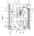
- FIG. 1 is a schematic structural view showing a whole structure of an image forming apparatus of an embodiment of the present invention
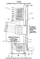
- FIG. 2 is a plan view of an image forming part and a sub-scanning conveyance part of the image forming apparatus shown in FIG. 1.
- the image forming apparatus has a structure where an image forming part (image forming means) 2 configured to form an image while a sheet is conveyed, a sub-scanning conveyance part (sub-scanning conveyance means) 3 configured to convey the sheet, and others are provided inside of an apparatus main body (housing) 1.
- Sheets not limited to papers
- Sheet feeding means including a sheet feeding cassette provided at a bottom part of the apparatus main body 1.
- a liquid drop is jetted onto the sheet 5 by the image forming part 2 so that an image is formed (recorded) on the sheet 5.
- the sheet 5 is discharged on a sheet discharging tray 7 formed on an upper surface of the apparatus main body 1 via a sheet discharge conveyance part (sheet discharge conveyance means) 6.
- the image forming apparatus includes an image reading part (scanner part) 11 configured to read the image.
- the image reading part is provided at an upper part of the sheet discharging tray 7 situated at an upper part of the apparatus main body 1.
- a scanning optical system 15 includes a lighting source 13 and a mirror 14 and a scanning optical system 18 includes mirrors 16 and 17 that are moved so that the image of a manuscript provided on a contact glass 12 is read out.
- a scanned manuscript image is read out as an image signal by an image reading element 20 provided at the back of a lens 19.
- the image signal that is read out is digitalized and image-processed so that printing data that are image-processed can be printed.
- a pressure plate 10 is provided on the contact glass 12 so as to press the manuscript.
- the image forming part 2 of the image forming apparatus has a structure where a carriage 23 is held movably in a main scanning direction by a guide rod 21 and a guide rail 22 (not shown).
- the carriage 23 can move in the main scanning direction driven by an endless timing belt 29 wound around and tensioned between a driving pulley 28A and an idler pulley 28B and driven by a main scanning motor 27.
- a recording head 24 is mounted on the carriage 23.
- the recording head 24 is formed by a liquid drop jet head configured to jet a liquid drop of each color.
- the carriage 23 is moved in a main scanning direction. While the sheet 5 is intermittently sent in a sheet conveyance direction (sub-scanning direction) by a sub-scanning conveyance part 3, the liquid drops are jetted from the recording head 24 which is a shuttle type head so that the image is formed.
- the recording head 24 includes two liquid drop jet heads 24k1 and 24k2 configured to jet black (Bk) ink, a liquid drop jet head 24c configured to jet cyan (C) ink, a liquid drop jet head 24m configured to jet magenta (M) ink, and a liquid drop jet head 24y configured to jet yellow (Y) ink.
- Color ink is supplied from respective sub tanks 25 provided in the carriage 23.
- ink cartridges 26 of respective colors can be detachably arranged from a front surface of the apparatus main body 1 to a cartridge arranging part.
- Black (Bk) ink, cyan (C) ink, magenta (M) ink, and yellow (Y) ink are received in the ink cartridges.
- Inks (recording liquid) are supplied from the ink cartridges 26 to the corresponding sub tanks 25 via tubes not shown.
- the black (Bk) ink is supplied from a single ink cartridge 26 to two sub tanks 25.
- a piezoelectric type recording head As the recording head 24, a piezoelectric type recording head, a thermal type recording head, an electrostatic type recording head, and others can be used.
- a piezoelectric type recording head a piezoelectric element is used as pressure generation means (actuator means) for putting ink under pressure in an ink path (pressure generation room) and a vibration plate forming a wall surface of the ink path is deformed so that the volume of the ink path is changed and the ink drop is jetted.
- the ink drop is jetted by pressure based bubbles generated by heating the ink in the ink path by using a heat generation resistant body.
- a vibration plate forming a wall surface of an ink path and an electrode face each other and the vibration plate is deformed by an electrostatic force generated between the vibration plate and the electrode so that the volume of the ink path is changed and the ink drop is jetted.
- a keeping and recovering apparatus 121 configured to restore and maintain a state of the nozzle of the recording head 24 is provided.
- the keeping and recovering apparatus 121 includes five caps 122a, 122b, 122c, 122d, and 122e, a wiper blade 124, a test jet receiving member 125, and others.
- the caps 122 are configured to cap the nozzle surfaces of the recording heads 24.
- the wiper blade 124 is configured to wipe the nozzle surfaces of the recording heads 24.
- the test jet receiving member 125 is used for test jetting that is jetting of the liquid drops not contributing to recording (image forming).
- a test jet receiving member 126 is provided in a non-printing area at another side in the scanning direction of the carriage 23, as shown in FIG. 2, a test jet receiving member 126 is provided.
- the test jet receiving member 126 is used for test jetting that is jetting of the liquid drops not contributing to recording (image forming) from five recording heads 24.
- five openings 127a, 127b, 127c, 127d, and 127e are formed in the test jet receiving member 126.
- the sub-scanning conveyance part 3 includes an endless conveyance belt 31, an electrostatic charging roller 34, a guide member 35, a pressing roller 36, two rollers 37, and a separation claw (not shown).
- the endless conveyance belt 31 is wound around a conveyance roller 32 which is a driving roller and an idler roller 33 which is a tension roller so that the conveyance direction of the sheet 5 fed from a lower part is changed by about 90 degrees and the sheet 5 is conveyed so as to face the image forming part 2.
- the electrostatic charging roller 34 is an electrostatic charging part configured to apply a high voltage that is an AC (alternating current) voltage from a high voltage electric power source so that a surface of the conveyance belt 31 is charged.
- the guide member 35 guides the conveyance belt 31 in an area facing the image forming part 2.
- the pressing roller 36 presses the sheet 5 to the conveyance belt 31 at a position facing the conveyance roller 32.
- the rollers 37 press at upper and lower sides of the sheet 5 where the image is formed by the image forming part 2.
- the separation claw is configured to separate the sheet 5 where the image is formed from the conveyance belt 31.
- the conveyance roller 32 is rotated by the sub-scanning motor 131 via a timing belt 132 and a timing roller 133, so that the conveyance belt 31 of the sub-scanning conveyance part 3 goes around in a sheet conveyance direction, namely a sub-scanning direction, in FIG. 2.
- the sheet feeding part 4 includes a sheet feeding cassette 41, a sheet feeding roller 42, a friction pad 43, and resist rollers 44.
- the sheet feeding cassette 41 is provided detachably from the front surface side of the apparatus main body 1 and holds a large number of the sheets 5.
- the sheet feeding roller 42 separates and sends the sheets 5 provided in the sheet feeding cassette 41 one by one.
- the fed sheet 5 is conveyed to the sub-scanning conveyance part 3 by the resist rollers 44.
- the sheet feeding roller 42 and the resist rollers 44 are driven and rotated by the sheet feeding motor 45 such as an HB type stepping motor via an sheet feeding clutch not shown.
- the sheet discharge conveyance part (sheet discharge conveyance means) 6 has sheet discharge rollers 61, 62 and 63 and a sheet discharge roller 64.
- the sheet discharge rollers 61 and 62 convey the sheet 5 where the image is formed.
- the sheet discharge rollers 63 send the sheet 5 out to the sheet discharge tray 7.
- a rotational amount of the conveyance roller 32 configured to drive the conveyance belt 31 is detected.
- a sub-scanning motor 131 is controlled.
- the sheet 5 is fed from the sheet feeding part 4 and the electric charge of the positive and negative electrodes is formed between the conveyance roller 32 and the pressing roller 36 so that the sheet 5 is sent to the conveyance belt 31 where unequal electric field is generated, the sheet 5 is immediately polarized following the direction of the electric field. As a result of this, the sheet 5 is adhered on the conveyance belt 31 by an electrostatic attraction force so as to be conveyed by the movement of the conveyance belt 31.
- the liquid drops are jetted from the recording head 24 onto the paper 5 corresponding to the printing data so that the image is formed (printed).
- a head end of the paper 5 where the image is formed is separated from the conveyance belt 31 by the separation claw 38. And then, the paper 5 is discharged to the sheet discharge conveyance part (sheet discharge conveyance means) 6.
- the carriage 23 is moved to a side of the keeping and recovering apparatus 121.
- a nozzle surface of the recording head 24 is capped by the cap 122 so that a wetted state of the nozzle is maintained and improper jetting due to ink dry can be prevented.
- the recording liquid is suctioned from the nozzle, that is nozzle suction or head suction is performed, and a recovering operation for discharging bottled up recording liquid or air bubbles is done.
- Wiping with the wiper blade 124 is done so that the ink adhered to the nozzle surface of the recording head 24 due to this recovering operation is removed. Furthermore, before recording is started or during the recording, test jet recording is performed so that liquid drops not contributing to recording (image forming) are jetted to the test jet receiving member 125. As a result of this, it is possible to maintain a stable jetting ability of the recording head 24.
- FIG. 3 is a structural view of a part where the engine unit of the image forming apparatus is provided.
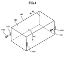
- FIG. 4 is a perspective view showing a frame 101 where the engine unit 100 is fixed.
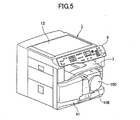
- FIG. 5 is a perspective view showing where the engine unit 100 of the image forming apparatus is provided is an apparatus main body 1.
- FIG. 6 is a perspective view showing where the engine unit 100 of the image forming apparatus is taken out from the apparatus main body 1.
- FIG. 7 is a perspective view of the engine unit 100 seen from a rear side of the apparatus main body 1.
- FIG. 8 is a perspective view of the engine unit 100 seen from a front side of the apparatus main body 1.
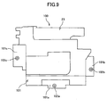
- FIG. 9 is a side view of the engine unit 100.
- an image forming part 2 and a sub-scanning conveyance part 3 as a conveyance part are unitized so as to form the engine unit 100.
- the image forming part 2 includes a carriage 23 having a recording head 24, a main scanning moving mechanism of the carriage 23, the keeping and recovering apparatus 121, and others.
- the sub-scanning conveyance part 3 includes the conveyance belt 31 and a driving mechanism of the conveyance belt 31.
- this engine unit 100 can be attached to or detached from the apparatus main body 1 via the front side of the apparatus main body 1.
- a belt cover 108 configured to cover the timing belt 132 is attached to a front surface of the engine unit 100 at a side of the apparatus main body 1.
- an operations part 9 is provided at an upper part at an entire surface side of the apparatus main body 1.
- the image forming part 2, the sub-scanning conveyance part 3, and others are supported by the frame 101. Furthermore, supporting pins 102a through 102c are provided at the upstream side and the downstream side in a sheet conveyance direction and at a lower part of the frame 101 so as to support the engine unit 100 in the apparatus main body 1.
- the supporting pins 102a through 102c are fixed to frame plates 101a through 101c forming the frame 101 by fixing means.
- a supporting point by the supporting pin 102a is called a first supporting point.
- a supporting point by the supporting pin 102b is called a second supporting point.
- a supporting point by the supporting pin 102c is called a third supporting point.
- holding parts 112a through 112c are provided at a housing 111 of the apparatus main body 1.
- the holding parts 112a through 112c have engaging holes where the supporting pins 102a through 102c are engaged when the engine unit 100 is inserted into the housing 101.
- direction of the supporting pins 102a through 102c are as shown in Fig. 7 through FIG. 8, that is an apparatus main body depth side direction, namely a direction where the engine unit 100 is inserted.
- the supporting pins 102a through 102c are inserted in and engaged by the holding parts 112a through 112c as shown so as to be supported in FIG. 3. Accordingly, in the apparatus main body 1 (housing 111), the engine unit 100 is three-point supported. In this case, the supporting pins 102a through 102c of the engine unit 100 can be rotated against the holding parts 112a through 112c of the housing 111 of the apparatus main body 1 and are supported in a state where the supporting pins 102a through 102c can be moved in a main scanning direction.
- the engine unit 100 is three-pint supported, stress in a case where the frame 101 of the engine unit 100 is fixed to the housing 111 of the apparatus main body 1 is not generated and therefore bending or straining is not generated. Therefore, the engine unit 100 can be provided in the apparatus main body 1 in a state where the image forming part 2 and the sub-scanning conveyance part 3 are held in a correct state or position.
- the flange part 1101 provided to the frame 101 of the engine unit 100 is fixed to the housing 111 of the apparatus main body 1 by fixing members such as the screws 1102, it is possible to tightly fix the frame to the housing 111 so that vibration of the engine unit 100 due to main scanning of the carriage 23, conveyance of the sheet by intermittent driving of the conveyance belt 31, or the like can be prevented.
- the engine unit 100 may be fixed to the apparatus main body 1 so that the frame 101 is twisted in different directions at the corresponding ends in the main scanning direction. If a twist or strain of the frame 101 is generated, influence is given to the conveyance belt 31 or the guide rod 21 so that unevenness of positions on the sheet where liquid drops jetted from the recording head 24 land is generated and the image quality is degraded. Thus it is not possible to both improve the maintainability and improve the image quality.
- the engine unit 100 per se can be moved.
- the vibration of the engine unit 100 may be transferred to the housing 111 of the apparatus main body 1 so that noise may be generated.
- a vibration prevention member (a plate spring in the example shown in FIG. 3) 114 is provided between the frame 101 of the engine unit 100 and a part 11a of the housing 111 of the apparatus main body 1.
- the vibration prevention member 114 is fixed to the housing 111 and presses the frame 101 of the engine unit 100 from an upstream side to a downstream side in the sheet conveyance direction, namely a recording medium conveyance direction.
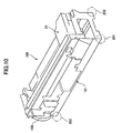
- FIG. 10 is a perspective view showing another example of three-point support of the engine unit.
- a corner part at a main apparatus body depth side may be a first supporting point 201
- a corner part at a side opposite to the first supporting point 201 may be a third supporting point 203
- a corner part at a side of the first supporting point 201 of the apparatus main body front side may be a second supporting point 202.
- FIG. 11 is a perspective view showing other example of the engine unit seen from a rear side of the apparatus main body.
- FIG. 12 is a perspective view showing other example of the engine unit seen from a front side of the apparatus main body.
- a corner part at a main apparatus body depth side may be the first supporting point 201
- a corner part at a side of the first supporting point 201 of the apparatus main body front side may be the second supporting point 202 (See FIG. 11)
- a center part at a side opposite to the sheet conveyance direction may be a third supporting point 203 (See FIG. 12).
- an arrangement position of the vibration prevention member 114 is not limited to the above-discussed examples. Examples shown in FIG. 13 through FIG. 15 may be applied.
- FIG. 13 is a structural view for explaining an installing position of a vibration preventing part
- FIG. 14 is a structural view for explaining an installing position of another example of the vibration preventing part
- FIG. 15 is a structural view for explaining an installing position of other example of the vibration preventing part.
- the vibration prevention member 114 may be arranged in at least either direction of the main scanning directions of the engine unit 100, namely moving directions of the image forming part. As shown in FIG. 14, the vibration prevention member 114 may be arranged at least at either upper side or downstream side of the sub-scanning direction of the engine unit 100. As shown in FIG. 15, the vibration prevention member 114 may be arranged in either upper or lower direction of the engine unit 100. The vibration prevention member 114 may be arranged by combining the examples shown in FIG. 13 through FIG. 15. It is preferable that the vibration prevention member be arranged at a part where the vibration can be decreased most, corresponding to the vibration of the engine unit 100 in the image forming apparatus.
- an elastic member such as a coil spring, sponge member, rubber member or mechanical shock absorbing device such as an oil dumper may be used.
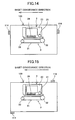
- FIG. 16 is a perspective view showing an example where the vibration preventing part is detachably provided in the apparatus main body.
- FIG. 17 is a perspective view showing a state where a member having the vibration preventing part is taken out from the apparatus main body.
- the vibration prevention member (plate spring) 114 may be provided at the cover member 111A arranged to the housing 111 in the apparatus main body 1. In this case, as shown in FIG. 17, the vibration prevention member 114 can be removed by taking out the cover member 111A.
- FIG. 18 is a block diagram for explaining another embodiment of the present invention.
- the image forming apparatus may have vibration prevention parts 214A and 214B provided at upstream side and down stream side in the sheet conveyance direction of the engine unit 100 where the vibration prevention parts 214A and 214B are configured to press the engine.unit 100 in opposite directions, a vibration detection part 221 configured to detect vibration of the engine unit 100, and a vibration prevention control part 221 configured to detect vibration based on a detection signal of the vibration detection part 221 and control vibration prevention parts 214A and 214B in a direction where the detected vibration is prevented.
- an image forming apparatus wherein an engine unit is detachably provided in an apparatus main body, the image forming apparatus characterized in that: the engine unit is formed by unitizing an image forming part configured to jet a liquid drop of recording liquid so that an image is formed on a recording medium, and a conveyance part configured to convey the recording medium; and the engine unit is three-point supported by a housing of the apparatus main body.
- a vibration prevention part may be provided between the engine unit and the housing so as to prevent vibration of the engine unit.
- the vibration prevention part may be come in contact with the engine unit and the housing.
- the vibration prevention part may be provided at least for either of moving directions of the image forming part of the engine unit.
- the vibration prevention part may be provided at least at one of an upstream side and a down stream side of the conveyance direction of the recording medium by the conveyance part of the engine unit.
- the vibration prevention part may be provided at least for one of an upper direction and a lower direction of the engine unit.
- the vibration prevention part may be a coil spring.
- the vibration prevention part may be a plate spring.
- the vibration prevention part may be an oil damper.
- the vibration prevention part may be a sponge member.
- the vibration prevention part may be a rubber member.
- the vibration prevention part may be fixed to the housing and has a plate spring configured to press in a recording medium conveyance direction from the housing side to the engine unit side.
- the vibration prevention part may be detachable.
- the vibration prevention part may include a part configured to vibrate the engine unit in a direction opposite to a vibration direction based on a detection result of vibration of the engine unit.
Landscapes
- Ink Jet (AREA)
- Accessory Devices And Overall Control Thereof (AREA)
- Common Mechanisms (AREA)
Abstract
the engine unit (100) is formed by unitizing an image forming part (2) configured to jet a liquid drop of recording liquid so that an image is formed on a recording medium (5), and a conveyance part (3) configured to convey the recording medium (5); and the engine unit (100) is three-point (102a-c) supported by a housing (111) of the apparatus main body (1).
Description
- The present invention generally relates to image forming apparatuses, and more particularly, an image forming apparatus having a structure where an engine unit can be detachably provided in an apparatus main body.
- An inkjet recording apparatus, for example, is known as an image forming apparatus such as a printer, facsimile, copier or a multiple function processing machine of the printer, facsimile, and copier. In the above-mentioned inkjet recording apparatus, while a recording medium is conveyed, a liquid drop of recording liquid (hereinafter "ink drop") is adhered to the recording medium by using a recording head (image forming part) having a liquid jet head configured to jet the liquid drop of the recording liquid, so that image forming such as recording or printing is performed. Hereinafter, the recording medium is called a paper or transferred material. However, there is no limitation of material for the paper or the transferred material.
- In such an inkjet recording apparatus, in order to correspond to personal use and office use, it is preferable that maintenance be performed when the user sees. Because of this, for example, in a serial type inkjet recording apparatus, an engine unit is formed by unitizing a recoding head configured to jet a liquid drop of recording liquid so that an image is formed on the recording medium, a carriage having the recording head, a scanning mechanism of the carriage, a conveyance mechanism configured to convey the recording medium, and others. In addition, this engine unit is detachably provided in the apparatus main body.
-
Japanese Patent No. 3404060 - In a case where the engine unit including the image forming part and the sheet conveyance part can be detachably provided in the apparatus main body, the following problems may happen.
- In a case where a belt conveyance device is configured to electrostatically attract the sheet to the conveyance belt and convey the sheet in order for the sheet to have high planarity with the recording head, if the engine unit is provided in the apparatus main body and bending or straining of the frame of the engine unit is generated, bending or straining of the conveyance belt is generated. Because of this, the sheet may not be conveyed with high planarity with the recording head. In addition, in the case of the serial type, straining of a guide member configured to guide a carriage having a recording head is generated so that main scanning may not be smoothly implemented and the distance between the recording head and the sheet may be changed.
- Thus, by unitizing the engine part, while the maintenance ability is improved, the gap between the sheet and the recording head required for inkjet recording and the planarity of the sheet may not be kept. Therefore, unevenness of positions where liquid drops are attached may happen so that image quality may be degraded.
- In addition, vibration due to the conveyance of the sheet by the sheet conveyance part, especially vibration in a case where the sheet is intermittently conveyed, and vibration due to reciprocal movement of the carriage having the recording head are generated so that the entire engine unit is vibrated.
- In this case, although the vibration may be prevented by completely fixing the engine unit to the apparatus main body, bending or straining of the engine unit per se may be easily generated.
- Accordingly, embodiments of the present invention may provide a novel and useful image forming apparatus in which the above-mentioned problems are alleviated or eliminated.
- More specifically, the embodiments of the present invention may provide an image forming apparatus whereby degradation of image quality is prevented and maintainability is improved, as mentioned in
claim 1. - The embodiments of the present invention may provide an image forming apparatus whereby degradation of the image quality is prevented, the maintainability is improved, and vibration is prevented, as mentioned in other claims.
- The embodiments of the present invention may provide an image forming apparatus wherein an engine unit is detachably provided in an apparatus main body, the image forming apparatus characterized in that:
- the engine unit is formed by unitizing an image forming part configured to jet a liquid drop of recording liquid so that an image is formed on a recording medium, and a conveyance part configured to convey the recording medium; and
- the engine unit is three-point supported by a housing of the apparatus main body.
- According to the embodiments of the present invention, the engine unit is supported at three points (three-point supported) by the housing of the apparatus main body so that four points are not fixed in where the engine unit is provided in the apparatus main body. Therefore, bending or straining a frame of the engine unit may not be generated. Hence, it is possible to keep a gap between a recording head and the recording medium such as a sheet and planarity of the recording medium. Therefore, it is possible to prevent degradation of image quality and improve maintainability.
- Other objects, features, and advantages of the present invention will become more apparent from the following detailed description of exemplary embodiments and the accompanying drawings, in which:
- FIG. 1 is a schematic structural view showing a whole structure of an image forming apparatus of an embodiment of the present invention;
- FIG. 2 is a plan view of an image forming part and a sub-scanning conveyance part of the image forming apparatus shown in FIG. 1;
- FIG. 3 is a structural view of a part where the engine unit of the image forming apparatus is provided;
- FIG. 4 is a perspective view showing a state where the engine unit is fixed;
- FIG. 5 is a perspective view showing a state where the engine unit of the image forming apparatus is provided in an apparatus main body;
- FIG. 6 is a perspective view showing a state where the engine unit of the image forming apparatus is taken out from the apparatus main body;
- FIG. 7 is a perspective view of the engine unit seen from a rear side of the apparatus main body;
- FIG. 8 is a perspective view of the engine unit seen from a front side of the apparatus main body;
- FIG. 9 is a side view of the engine unit;
- FIG. 10 is a perspective view showing another example of three-point support of the engine unit;
- FIG. 11 is a perspective view showing another example of the engine unit seen from a rear side of the apparatus main body;
- FIG. 12 is a perspective view showing another example of the engine unit seen from a front side of the apparatus main body;
- FIG. 13 is a structural view for explaining an installing position of a vibration preventing part;
- FIG. 14 is a structural view for explaining an installing position of another example of the vibration preventing part;
- FIG. 15 is a structural view for explaining an installing position of another example of the vibration preventing part;
- FIG. 16 is a perspective view showing an example where the vibration preventing part is detachably provided in the apparatus main body;
- FIG. 17 is a perspective view showing a state where a member having the vibration preventing part is taken out from the apparatus main body; and
- FIG. 18 is a block diagram for explaining another embodiment of the present invention.
- A description of the present invention is now given, with reference to FIG. 1 through FIG. 18 including embodiments of the present invention.
- First, an embodiment of an image forming apparatus of the embodiment of the present invention is discussed with reference to FIG. 1 and FIG. 2. Here, FIG. 1 is a schematic structural view showing a whole structure of an image forming apparatus of an embodiment of the present invention, and FIG. 2 is a plan view of an image forming part and a sub-scanning conveyance part of the image forming apparatus shown in FIG. 1. In the following description, the image forming apparatus has a structure where an image forming part (image forming means) 2 configured to form an image while a sheet is conveyed, a sub-scanning conveyance part (sub-scanning conveyance means) 3 configured to convey the sheet, and others are provided inside of an apparatus main body (housing) 1. Recording media (hereinafter "Sheets" not limited to papers) 5 are fed one by one from a sheet feeding part (sheet feeding means) including a sheet feeding cassette provided at a bottom part of the apparatus
main body 1. While thesheet 5 is intermittently conveyed at a position facing theimage forming part 2 by thesub-scanning conveyance part 3, a liquid drop is jetted onto thesheet 5 by theimage forming part 2 so that an image is formed (recorded) on thesheet 5. After that, in a case of one side printing, thesheet 5 is discharged on asheet discharging tray 7 formed on an upper surface of the apparatusmain body 1 via a sheet discharge conveyance part (sheet discharge conveyance means) 6. - As an input system of image data (printing data) formed by the
image forming part 2, the image forming apparatus includes an image reading part (scanner part) 11 configured to read the image. The image reading part is provided at an upper part of thesheet discharging tray 7 situated at an upper part of the apparatusmain body 1. In theimage reading part 11, a scanningoptical system 15 includes alighting source 13 and amirror 14 and a scanningoptical system 18 includesmirrors contact glass 12 is read out. A scanned manuscript image is read out as an image signal by animage reading element 20 provided at the back of alens 19. The image signal that is read out is digitalized and image-processed so that printing data that are image-processed can be printed. Apressure plate 10 is provided on thecontact glass 12 so as to press the manuscript. - As shown in FIG. 2, the
image forming part 2 of the image forming apparatus has a structure where acarriage 23 is held movably in a main scanning direction by aguide rod 21 and a guide rail 22 (not shown). Thecarriage 23 can move in the main scanning direction driven by anendless timing belt 29 wound around and tensioned between a drivingpulley 28A and anidler pulley 28B and driven by amain scanning motor 27. - A
recording head 24 is mounted on thecarriage 23. Therecording head 24 is formed by a liquid drop jet head configured to jet a liquid drop of each color. Thecarriage 23 is moved in a main scanning direction. While thesheet 5 is intermittently sent in a sheet conveyance direction (sub-scanning direction) by asub-scanning conveyance part 3, the liquid drops are jetted from therecording head 24 which is a shuttle type head so that the image is formed. - The
recording head 24 includes two liquid drop jet heads 24k1 and 24k2 configured to jet black (Bk) ink, a liquiddrop jet head 24c configured to jet cyan (C) ink, a liquiddrop jet head 24m configured to jet magenta (M) ink, and a liquiddrop jet head 24y configured to jet yellow (Y) ink. Color ink is supplied fromrespective sub tanks 25 provided in thecarriage 23. - On the other hand, as shown in FIG. 1,
ink cartridges 26 of respective colors can be detachably arranged from a front surface of the apparatusmain body 1 to a cartridge arranging part. Black (Bk) ink, cyan (C) ink, magenta (M) ink, and yellow (Y) ink are received in the ink cartridges. Inks (recording liquid) are supplied from theink cartridges 26 to thecorresponding sub tanks 25 via tubes not shown. The black (Bk) ink is supplied from asingle ink cartridge 26 to twosub tanks 25. - As the
recording head 24, a piezoelectric type recording head, a thermal type recording head, an electrostatic type recording head, and others can be used. In a case of the piezoelectric type recording head, a piezoelectric element is used as pressure generation means (actuator means) for putting ink under pressure in an ink path (pressure generation room) and a vibration plate forming a wall surface of the ink path is deformed so that the volume of the ink path is changed and the ink drop is jetted. In a case of the thermal type recording head, the ink drop is jetted by pressure based bubbles generated by heating the ink in the ink path by using a heat generation resistant body. In a case of an electrostatic type recording head, a vibration plate forming a wall surface of an ink path and an electrode face each other and the vibration plate is deformed by an electrostatic force generated between the vibration plate and the electrode so that the volume of the ink path is changed and the ink drop is jetted. - In a non-printing area at one side in a scanning direction of the
carriage 23, as shown in FIG. 2, a keeping and recoveringapparatus 121 configured to restore and maintain a state of the nozzle of therecording head 24 is provided. The keeping and recoveringapparatus 121 includes fivecaps wiper blade 124, a testjet receiving member 125, and others. The caps 122 are configured to cap the nozzle surfaces of the recording heads 24. Thewiper blade 124 is configured to wipe the nozzle surfaces of the recording heads 24. The testjet receiving member 125 is used for test jetting that is jetting of the liquid drops not contributing to recording (image forming). - Furthermore, in a non-printing area at another side in the scanning direction of the
carriage 23, as shown in FIG. 2, a testjet receiving member 126 is provided. The testjet receiving member 126 is used for test jetting that is jetting of the liquid drops not contributing to recording (image forming) from five recording heads 24. As corresponding to therecording head 24, fiveopenings jet receiving member 126. - The
sub-scanning conveyance part 3 includes anendless conveyance belt 31, an electrostatic charging roller 34, a guide member 35, apressing roller 36, two rollers 37, and a separation claw (not shown). Theendless conveyance belt 31 is wound around aconveyance roller 32 which is a driving roller and anidler roller 33 which is a tension roller so that the conveyance direction of thesheet 5 fed from a lower part is changed by about 90 degrees and thesheet 5 is conveyed so as to face theimage forming part 2. The electrostatic charging roller 34 is an electrostatic charging part configured to apply a high voltage that is an AC (alternating current) voltage from a high voltage electric power source so that a surface of theconveyance belt 31 is charged. The guide member 35 guides theconveyance belt 31 in an area facing theimage forming part 2. Thepressing roller 36 presses thesheet 5 to theconveyance belt 31 at a position facing theconveyance roller 32. The rollers 37 press at upper and lower sides of thesheet 5 where the image is formed by theimage forming part 2. The separation claw is configured to separate thesheet 5 where the image is formed from theconveyance belt 31. - The
conveyance roller 32 is rotated by thesub-scanning motor 131 via atiming belt 132 and atiming roller 133, so that theconveyance belt 31 of thesub-scanning conveyance part 3 goes around in a sheet conveyance direction, namely a sub-scanning direction, in FIG. 2. - The
sheet feeding part 4 includes asheet feeding cassette 41, asheet feeding roller 42, afriction pad 43, and resist rollers 44. Thesheet feeding cassette 41 is provided detachably from the front surface side of the apparatusmain body 1 and holds a large number of thesheets 5. Thesheet feeding roller 42 separates and sends thesheets 5 provided in thesheet feeding cassette 41 one by one. Thefed sheet 5 is conveyed to thesub-scanning conveyance part 3 by the resist rollers 44. Thesheet feeding roller 42 and the resist rollers 44 are driven and rotated by thesheet feeding motor 45 such as an HB type stepping motor via an sheet feeding clutch not shown. - The sheet discharge conveyance part (sheet discharge conveyance means) 6 has
sheet discharge rollers sheet discharge roller 64. Thesheet discharge rollers sheet 5 where the image is formed. Thesheet discharge rollers 63 send thesheet 5 out to thesheet discharge tray 7. - In the image forming apparatus having the above-discussed structure, a rotational amount of the
conveyance roller 32 configured to drive theconveyance belt 31 is detected. Corresponding to the detected rotational amount, asub-scanning motor 131 is controlled. - By applying a high voltage of a rectangular wave positive negative electrode that is an AC voltage from an AC bias supply part to an electrostatic charge roller 34, positive and negative electrical charges are reciprocally applied to the surface layer of the
conveyance belt 31 in a belt shape against the conveyance direction of theconveyance belt 31 because the electrostatic charge roller 34 comes in contact with the insulation layer (surface layer) of theconveyance belt 31. As a result of this, unequal electrical fields are generated due to electric charges being generated on theconveyance belt 31 at a designated charge width. - In a case where the
sheet 5 is fed from thesheet feeding part 4 and the electric charge of the positive and negative electrodes is formed between theconveyance roller 32 and thepressing roller 36 so that thesheet 5 is sent to theconveyance belt 31 where unequal electric field is generated, thesheet 5 is immediately polarized following the direction of the electric field. As a result of this, thesheet 5 is adhered on theconveyance belt 31 by an electrostatic attraction force so as to be conveyed by the movement of theconveyance belt 31. - While the
paper 5 is conveyed intermittently by theconveyance belt 31, the liquid drops are jetted from therecording head 24 onto thepaper 5 corresponding to the printing data so that the image is formed (printed). A head end of thepaper 5 where the image is formed is separated from theconveyance belt 31 by theseparation claw 38. And then, thepaper 5 is discharged to the sheet discharge conveyance part (sheet discharge conveyance means) 6. - During waiting for printing, the
carriage 23 is moved to a side of the keeping and recoveringapparatus 121. A nozzle surface of therecording head 24 is capped by the cap 122 so that a wetted state of the nozzle is maintained and improper jetting due to ink dry can be prevented. In addition, where therecording head 24 is covered by thecap 122a, the recording liquid is suctioned from the nozzle, that is nozzle suction or head suction is performed, and a recovering operation for discharging bottled up recording liquid or air bubbles is done. - Wiping with the
wiper blade 124 is done so that the ink adhered to the nozzle surface of therecording head 24 due to this recovering operation is removed. Furthermore, before recording is started or during the recording, test jet recording is performed so that liquid drops not contributing to recording (image forming) are jetted to the testjet receiving member 125. As a result of this, it is possible to maintain a stable jetting ability of therecording head 24. - Next a supporting structure and a vibration control structure of the engine unit in the image forming apparatus are discussed with reference to FIG. 3 through FIG. 9.
- Here, FIG. 3 is a structural view of a part where the engine unit of the image forming apparatus is provided. FIG. 4 is a perspective view showing a
frame 101 where theengine unit 100 is fixed. FIG. 5 is a perspective view showing where theengine unit 100 of the image forming apparatus is provided is an apparatusmain body 1. FIG. 6 is a perspective view showing where theengine unit 100 of the image forming apparatus is taken out from the apparatusmain body 1. FIG. 7 is a perspective view of theengine unit 100 seen from a rear side of the apparatusmain body 1. FIG. 8 is a perspective view of theengine unit 100 seen from a front side of the apparatusmain body 1. FIG. 9 is a side view of theengine unit 100. - In this image forming apparatus, as shown in FIG. 3 and FIG. 5 through FIG. 9, an
image forming part 2 and asub-scanning conveyance part 3 as a conveyance part are unitized so as to form theengine unit 100. - The
image forming part 2 includes acarriage 23 having arecording head 24, a main scanning moving mechanism of thecarriage 23, the keeping and recoveringapparatus 121, and others. Thesub-scanning conveyance part 3 includes theconveyance belt 31 and a driving mechanism of theconveyance belt 31. - As shown in FIG. 3 and FIG. 5 through FIG. 9, this
engine unit 100 can be attached to or detached from the apparatusmain body 1 via the front side of the apparatusmain body 1. Abelt cover 108 configured to cover thetiming belt 132 is attached to a front surface of theengine unit 100 at a side of the apparatusmain body 1. In addition, anoperations part 9 is provided at an upper part at an entire surface side of the apparatusmain body 1. - In this
engine unit 100, theimage forming part 2, thesub-scanning conveyance part 3, and others are supported by theframe 101. Furthermore, supportingpins 102a through 102c are provided at the upstream side and the downstream side in a sheet conveyance direction and at a lower part of theframe 101 so as to support theengine unit 100 in the apparatusmain body 1. - As shown in FIG. 7 though FIG. 9, the supporting
pins 102a through 102c are fixed to frameplates 101a through 101c forming theframe 101 by fixing means. Here, a supporting point by the supportingpin 102a is called a first supporting point. A supporting point by the supportingpin 102b is called a second supporting point. A supporting point by the supportingpin 102c is called a third supporting point. On the other hand, as shown in FIG. 3, holdingparts 112a through 112c are provided at ahousing 111 of the apparatusmain body 1. The holdingparts 112a through 112c have engaging holes where the supportingpins 102a through 102c are engaged when theengine unit 100 is inserted into thehousing 101. - While the
frame 101 is indicated in a permeating state in FIG. 3 for the convenience of explanation, direction of the supportingpins 102a through 102c are as shown in Fig. 7 through FIG. 8, that is an apparatus main body depth side direction, namely a direction where theengine unit 100 is inserted. - Therefore, when the
engine unit 100 is provided in the apparatus main body 1 (housing 111) as shown in FIG. 5, the supportingpins 102a through 102c are inserted in and engaged by the holdingparts 112a through 112c as shown so as to be supported in FIG. 3. Accordingly, in the apparatus main body 1 (housing 111), theengine unit 100 is three-point supported. In this case, the supportingpins 102a through 102c of theengine unit 100 can be rotated against the holdingparts 112a through 112c of thehousing 111 of the apparatusmain body 1 and are supported in a state where the supportingpins 102a through 102c can be moved in a main scanning direction. - Thus, since the
engine unit 100 is three-pint supported, stress in a case where theframe 101 of theengine unit 100 is fixed to thehousing 111 of the apparatusmain body 1 is not generated and therefore bending or straining is not generated. Therefore, theengine unit 100 can be provided in the apparatusmain body 1 in a state where theimage forming part 2 and thesub-scanning conveyance part 3 are held in a correct state or position. - Because of this, it is possible to prevent the
conveyance belt 31 being deformed or twisted so that change of the gap between therecording head 24 and the sheet conveyed by theconveyance belt 31 is prevented. Alternatively, it is possible to prevent an increase of unevenness of positions on the sheet where liquid drops jetted from therecording head 24 land, the unevenness being due to shift of theguide rod 21 guiding thecarriage 23 so as to be parallel to the surface of theconveyance belt 31. In addition, it is possible to prevent thecarriage 23 from sliding. Therefore, while maintainability is improved by unitization, degradation of the image quality can be prevented. - In other words, if the above-discussed three-point supporting is not applied but instead, for example, as shown in FIG. 4, the
flange part 1101 provided to theframe 101 of theengine unit 100 is fixed to thehousing 111 of the apparatusmain body 1 by fixing members such as thescrews 1102, it is possible to tightly fix the frame to thehousing 111 so that vibration of theengine unit 100 due to main scanning of thecarriage 23, conveyance of the sheet by intermittent driving of theconveyance belt 31, or the like can be prevented. - However, in the case where the
frame 101 is fixed to thehousing 111 of the apparatusmain body 1 by the fixing members, stress due to an arrangement position error is applied to theframe 101. As a result of this, as indicated by arrows A1 and A2 of FIG. 4, theengine unit 100 may be fixed to the apparatusmain body 1 so that theframe 101 is twisted in different directions at the corresponding ends in the main scanning direction. If a twist or strain of theframe 101 is generated, influence is given to theconveyance belt 31 or theguide rod 21 so that unevenness of positions on the sheet where liquid drops jetted from therecording head 24 land is generated and the image quality is degraded. Thus it is not possible to both improve the maintainability and improve the image quality. - On the other hand, in the case where the
engine unit 100 is three-point supported in the apparatusmain body 1, it is possible to reduce generation of twisting or straining of theframe 101. - In this case, since the
frame 101 can be moved due to the main scanning of thecarriage 23 or intermittent conveyance driving by theconveyance belt 31, theengine unit 100 per se can be moved. The vibration of theengine unit 100 may be transferred to thehousing 111 of the apparatusmain body 1 so that noise may be generated. - Because of this, in this embodiment as shown in FIG. 3, a vibration prevention member (a plate spring in the example shown in FIG. 3) 114 is provided between the
frame 101 of theengine unit 100 and a part 11a of thehousing 111 of the apparatusmain body 1. Thevibration prevention member 114 is fixed to thehousing 111 and presses theframe 101 of theengine unit 100 from an upstream side to a downstream side in the sheet conveyance direction, namely a recording medium conveyance direction. - Under this structure, since the
engine unit 100 can be rotated with respect to the supportingpin 102a, the whole of theengine unit 100 is pressed by thevibration prevention member 114 toward the downstream side in the sheet conveyance direction in FIG. 3. As a result of this, the vibration of theengine unit 100 per se due to the main scanning of thecarriage 23 or intermittent conveyance driving by theconveyance belt 31 is prevented. Hence, it is possible to prevent the vibration of the apparatusmain body 1 so that generation of noise can be prevented. - In the meantime, the three-point support of the
engine unit 100 is not limited to the above-discussed supporting pins. An example shown in FIG. 3 can be applied. Here, FIG. 10 is a perspective view showing another example of three-point support of the engine unit. As shown in FIG. 10, in theframe 101 of theengine unit 100, a corner part at a main apparatus body depth side may be a firstsupporting point 201, a corner part at a side opposite to the first supportingpoint 201 may be a thirdsupporting point 203, and a corner part at a side of the first supportingpoint 201 of the apparatus main body front side may be a secondsupporting point 202. - Alternatively, examples show in FIG. 11 and FIG. 12 can be applied. Here, FIG. 11 is a perspective view showing other example of the engine unit seen from a rear side of the apparatus main body. FIG. 12 is a perspective view showing other example of the engine unit seen from a front side of the apparatus main body. As shown in FIG. 11, in the
frame 101 of theengine unit 100, a corner part at a main apparatus body depth side may be the first supportingpoint 201, a corner part at a side of the first supportingpoint 201 of the apparatus main body front side may be the second supporting point 202 (See FIG. 11), and a center part at a side opposite to the sheet conveyance direction may be a third supporting point 203 (See FIG. 12). - In addition, an arrangement position of the
vibration prevention member 114 is not limited to the above-discussed examples. Examples shown in FIG. 13 through FIG. 15 may be applied. Here, FIG. 13 is a structural view for explaining an installing position of a vibration preventing part, FIG. 14 is a structural view for explaining an installing position of another example of the vibration preventing part, and FIG. 15 is a structural view for explaining an installing position of other example of the vibration preventing part. - As shown in FIG. 13, the
vibration prevention member 114 may be arranged in at least either direction of the main scanning directions of theengine unit 100, namely moving directions of the image forming part. As shown in FIG. 14, thevibration prevention member 114 may be arranged at least at either upper side or downstream side of the sub-scanning direction of theengine unit 100. As shown in FIG. 15, thevibration prevention member 114 may be arranged in either upper or lower direction of theengine unit 100. Thevibration prevention member 114 may be arranged by combining the examples shown in FIG. 13 through FIG. 15. It is preferable that the vibration prevention member be arranged at a part where the vibration can be decreased most, corresponding to the vibration of theengine unit 100 in the image forming apparatus. - In addition, as the vibration prevention member, other than a plate spring, an elastic member such as a coil spring, sponge member, rubber member or mechanical shock absorbing device such as an oil dumper may be used.
- In addition, by detachably providing the vibration prevention part to the apparatus main body, it is possible to correspond to time-based change of the vibration of the
engine unit 100. FIG. 16 is a perspective view showing an example where the vibration preventing part is detachably provided in the apparatus main body. FIG. 17 is a perspective view showing a state where a member having the vibration preventing part is taken out from the apparatus main body. - As shown in FIG. 16, the vibration prevention member (plate spring) 114 may be provided at the
cover member 111A arranged to thehousing 111 in the apparatusmain body 1. In this case, as shown in FIG. 17, thevibration prevention member 114 can be removed by taking out thecover member 111A. - FIG. 18 is a block diagram for explaining another embodiment of the present invention. As shown in FIG. 18, the image forming apparatus may have
vibration prevention parts engine unit 100 where thevibration prevention parts engine.unit 100 in opposite directions, avibration detection part 221 configured to detect vibration of theengine unit 100, and a vibrationprevention control part 221 configured to detect vibration based on a detection signal of thevibration detection part 221 and controlvibration prevention parts - According to the above-discussed embodiments of the present invention, it is possible to provide an image forming apparatus wherein an engine unit is detachably provided in an apparatus main body, the image forming apparatus characterized in that: the engine unit is formed by unitizing an image forming part configured to jet a liquid drop of recording liquid so that an image is formed on a recording medium, and a conveyance part configured to convey the recording medium; and the engine unit is three-point supported by a housing of the apparatus main body.
- In the image forming apparatus, a vibration prevention part may be provided between the engine unit and the housing so as to prevent vibration of the engine unit. The vibration prevention part may be come in contact with the engine unit and the housing.
- The vibration prevention part may be provided at least for either of moving directions of the image forming part of the engine unit. The vibration prevention part may be provided at least at one of an upstream side and a down stream side of the conveyance direction of the recording medium by the conveyance part of the engine unit. The vibration prevention part may be provided at least for one of an upper direction and a lower direction of the engine unit.
- The vibration prevention part may be a coil spring. The vibration prevention part may be a plate spring. The vibration prevention part may be an oil damper. The vibration prevention part may be a sponge member. The vibration prevention part may be a rubber member.
- The vibration prevention part may be fixed to the housing and has a plate spring configured to press in a recording medium conveyance direction from the housing side to the engine unit side. The vibration prevention part may be detachable.
- The vibration prevention part may include a part configured to vibrate the engine unit in a direction opposite to a vibration direction based on a detection result of vibration of the engine unit.
- The present invention is not limited to these embodiments, but variations and modifications may be made without departing from the scope of the present invention.
Claims (10)
- An image forming apparatus wherein an engine unit is detachably provided in an apparatus main body, the image forming apparatus characterized in that:the engine unit is formed by unitizing an image forming part, which is configured to jet a liquid drop of recording liquid so that an image is formed on a recording medium, and a conveyance part, which is configured to convey the recording medium; andthe engine unit is three-point supported by a housing of the apparatus main body.
- An image forming apparatus according to claim 1, wherein:a vibration prevention part is provided between the engine unit and the housing so as to prevent vibration of the engine unit.
- An image forming apparatus according to claim 2, wherein:the vibration prevention part comes in contact with the engine unit and the housing.
- An image forming apparatus according to claim 2 or 3, wherein:a vibration prevention part is provided at either or both sides of the image forming part of the engine unit relative to its direction of movement.
- An image forming apparatus according to any one of claims 2 through 4, wherein:a vibration prevention part is provided at least at one of an upstream side and a down stream side of the conveyance direction of the recording medium by the conveyance part of the engine unit.
- An image forming apparatus according to any one of claims 2 through 5, wherein:a vibration prevention part is provided either above or below the engine unit or both above and below the engine unit.
- An image forming apparatus according to any one of claims 1 through 6, wherein:the vibration prevention part comprises at least one of :a coil spring;a plate spring;an oil damper;a sponge member;a rubber member.
- An image forming apparatus according to any one of claims 1 through 3, wherein:the vibration prevention part is fixed to the housing and has a plate spring configured to press in a recording medium conveyance direction from the housing side to the engine unit side.
- An image forming apparatus according to any one of claims 1 through 3, wherein:the vibration prevention part is detachable.
- An image forming apparatus according to any one of claims 1 through 3, wherein:the vibration prevention part includes a part configured to vibrate the engine unit in a direction opposite to a vibration direction based on a detection result of vibration of the engine unit.
Applications Claiming Priority (1)
| Application Number | Priority Date | Filing Date | Title |
|---|---|---|---|
| JP2005269495A JP4679316B2 (en) | 2005-09-16 | 2005-09-16 | Image forming apparatus |
Publications (3)
| Publication Number | Publication Date |
|---|---|
| EP1764229A2 true EP1764229A2 (en) | 2007-03-21 |
| EP1764229A3 EP1764229A3 (en) | 2009-09-09 |
| EP1764229B1 EP1764229B1 (en) | 2016-05-18 |
Family
ID=37499295
Family Applications (1)
| Application Number | Title | Priority Date | Filing Date |
|---|---|---|---|
| EP06254780.7A Not-in-force EP1764229B1 (en) | 2005-09-16 | 2006-09-14 | Image forming apparatus |
Country Status (2)
| Country | Link |
|---|---|
| EP (1) | EP1764229B1 (en) |
| JP (1) | JP4679316B2 (en) |
Cited By (1)
| Publication number | Priority date | Publication date | Assignee | Title |
|---|---|---|---|---|
| US20110141181A1 (en) * | 2009-12-14 | 2011-06-16 | Ricoh Company, Ltd., | Image forming apparatus capable of effectively damping vibration |
Families Citing this family (5)
| Publication number | Priority date | Publication date | Assignee | Title |
|---|---|---|---|---|
| JPWO2009119084A1 (en) | 2008-03-25 | 2011-07-21 | セイコーエプソン株式会社 | Liquid supply channel device and liquid ejecting apparatus using the same |
| JP5153518B2 (en) * | 2008-08-26 | 2013-02-27 | 理想科学工業株式会社 | Image recording device |
| JP5517737B2 (en) * | 2010-05-17 | 2014-06-11 | キヤノン株式会社 | Image forming apparatus |
| JP2012024984A (en) * | 2010-07-21 | 2012-02-09 | Seiko Epson Corp | Recording apparatus |
| JP6020244B2 (en) * | 2013-02-18 | 2016-11-02 | ブラザー工業株式会社 | Inkjet recording device |
Family Cites Families (12)
| Publication number | Priority date | Publication date | Assignee | Title |
|---|---|---|---|---|
| JPH02107471A (en) * | 1988-10-17 | 1990-04-19 | Hitachi Ltd | Driving method of linear moving body, driving device and printer |
| JP3342317B2 (en) * | 1996-09-25 | 2002-11-05 | 株式会社ピーエフユー | Support structure of optical unit of image reading device |
| JPH11277764A (en) * | 1998-03-27 | 1999-10-12 | Toshiba Tec Corp | Inkjet printer |
| JP2003270898A (en) * | 1998-05-07 | 2003-09-25 | Ricoh Co Ltd | Image forming device |
| JPH11352740A (en) * | 1998-06-04 | 1999-12-24 | Ricoh Co Ltd | Image forming device |
| JP2000310930A (en) * | 1999-04-27 | 2000-11-07 | Canon Inc | Image forming device |
| JP3692926B2 (en) * | 2000-02-02 | 2005-09-07 | カシオ電子工業株式会社 | Frame connection structure of image forming apparatus |
| JP3787510B2 (en) * | 2001-09-07 | 2006-06-21 | キヤノン株式会社 | Recording device |
| JP4000446B2 (en) * | 2001-12-20 | 2007-10-31 | 富士ゼロックス株式会社 | Image forming apparatus and image forming unit used therefor |
| JP4387645B2 (en) * | 2002-08-09 | 2009-12-16 | キヤノン株式会社 | Recording device |
| JP4473079B2 (en) * | 2003-09-19 | 2010-06-02 | 株式会社リコー | Image forming apparatus |
| JP2005178024A (en) * | 2003-12-16 | 2005-07-07 | Seiko Epson Corp | Printing device |
-
2005
- 2005-09-16 JP JP2005269495A patent/JP4679316B2/en not_active Expired - Fee Related
-
2006
- 2006-09-14 EP EP06254780.7A patent/EP1764229B1/en not_active Not-in-force
Non-Patent Citations (1)
| Title |
|---|
| None |
Cited By (5)
| Publication number | Priority date | Publication date | Assignee | Title |
|---|---|---|---|---|
| US20110141181A1 (en) * | 2009-12-14 | 2011-06-16 | Ricoh Company, Ltd., | Image forming apparatus capable of effectively damping vibration |
| EP2332732A3 (en) * | 2009-12-14 | 2011-06-22 | Ricoh Company, Ltd. | Image forming apparatus capable of effectively damping vibration |
| CN102166893A (en) * | 2009-12-14 | 2011-08-31 | 株式会社理光 | Image forming apparatus capable of effectively damping vibration |
| US8419156B2 (en) | 2009-12-14 | 2013-04-16 | Ricoh Company, Ltd. | Image forming apparatus capable of effectively damping vibration |
| CN102166893B (en) * | 2009-12-14 | 2013-06-26 | 株式会社理光 | Image forming apparatus capable of effectively damping vibration |
Also Published As
| Publication number | Publication date |
|---|---|
| JP4679316B2 (en) | 2011-04-27 |
| JP2007076271A (en) | 2007-03-29 |
| EP1764229B1 (en) | 2016-05-18 |
| EP1764229A3 (en) | 2009-09-09 |
Similar Documents
| Publication | Publication Date | Title |
|---|---|---|
| US7753500B2 (en) | Image forming apparatus | |
| US7496326B2 (en) | Electrostatic attraction device and image forming apparatus using the same | |
| US7784900B2 (en) | Imaging apparatus | |
| US7510263B2 (en) | Image forming apparatus | |
| JP4610369B2 (en) | Image forming apparatus | |
| EP1764229B1 (en) | Image forming apparatus | |
| JP4671781B2 (en) | Image forming apparatus | |
| JP2009119745A (en) | Image forming apparatus | |
| US8052276B2 (en) | Image forming apparatus and belt conveying device | |
| JP4688191B2 (en) | Sheet material conveying apparatus and image forming apparatus | |
| JP4560336B2 (en) | Recording device | |
| US7572002B2 (en) | Image forming apparatus and adjusting method of image forming apparatus | |
| US20080012921A1 (en) | Image forming apparatus | |
| JP4460374B2 (en) | Electrostatic transfer device and image forming apparatus | |
| JP4651487B2 (en) | Image forming apparatus | |
| JP4111503B2 (en) | Image forming apparatus | |
| US8833929B2 (en) | Image forming apparatus | |
| JP4340223B2 (en) | Electrostatic adsorption device and image forming apparatus using the same | |
| JP5037180B2 (en) | Image forming apparatus | |
| JP4850034B2 (en) | Image forming apparatus | |
| JP4614719B2 (en) | Image forming apparatus | |
| JP2008155427A (en) | Conveying apparatus and image forming apparatus | |
| US20070115319A1 (en) | Image forming apparatus, maintenance-recovery mechanism, and suction pump | |
| JPH08248707A (en) | Image forming device | |
| JP2007126269A (en) | Sheet holding device and image forming apparatus |
Legal Events
| Date | Code | Title | Description |
|---|---|---|---|
| PUAI | Public reference made under article 153(3) epc to a published international application that has entered the european phase |
Free format text: ORIGINAL CODE: 0009012 |
|
| 17P | Request for examination filed |
Effective date: 20060925 |
|
| AK | Designated contracting states |
Kind code of ref document: A2 Designated state(s): AT BE BG CH CY CZ DE DK EE ES FI FR GB GR HU IE IS IT LI LT LU LV MC NL PL PT RO SE SI SK TR |
|
| AX | Request for extension of the european patent |
Extension state: AL BA HR MK YU |
|
| PUAL | Search report despatched |
Free format text: ORIGINAL CODE: 0009013 |
|
| AK | Designated contracting states |
Kind code of ref document: A3 Designated state(s): AT BE BG CH CY CZ DE DK EE ES FI FR GB GR HU IE IS IT LI LT LU LV MC NL PL PT RO SE SI SK TR |
|
| AX | Request for extension of the european patent |
Extension state: AL BA HR MK RS |
|
| AKX | Designation fees paid |
Designated state(s): DE ES FR GB IT NL |
|
| 17Q | First examination report despatched |
Effective date: 20131118 |
|
| GRAP | Despatch of communication of intention to grant a patent |
Free format text: ORIGINAL CODE: EPIDOSNIGR1 |
|
| INTG | Intention to grant announced |
Effective date: 20160112 |
|
| GRAS | Grant fee paid |
Free format text: ORIGINAL CODE: EPIDOSNIGR3 |
|
| GRAA | (expected) grant |
Free format text: ORIGINAL CODE: 0009210 |
|
| AK | Designated contracting states |
Kind code of ref document: B1 Designated state(s): DE ES FR GB IT NL |
|
| REG | Reference to a national code |
Ref country code: GB Ref legal event code: FG4D |
|
| REG | Reference to a national code |
Ref country code: DE Ref legal event code: R096 Ref document number: 602006049110 Country of ref document: DE |
|
| REG | Reference to a national code |
Ref country code: NL Ref legal event code: MP Effective date: 20160518 Ref country code: FR Ref legal event code: PLFP Year of fee payment: 11 |
|
| PG25 | Lapsed in a contracting state [announced via postgrant information from national office to epo] |
Ref country code: NL Free format text: LAPSE BECAUSE OF FAILURE TO SUBMIT A TRANSLATION OF THE DESCRIPTION OR TO PAY THE FEE WITHIN THE PRESCRIBED TIME-LIMIT Effective date: 20160518 |
|
| PG25 | Lapsed in a contracting state [announced via postgrant information from national office to epo] |
Ref country code: ES Free format text: LAPSE BECAUSE OF FAILURE TO SUBMIT A TRANSLATION OF THE DESCRIPTION OR TO PAY THE FEE WITHIN THE PRESCRIBED TIME-LIMIT Effective date: 20160518 |
|
| PG25 | Lapsed in a contracting state [announced via postgrant information from national office to epo] |
Ref country code: IT Free format text: LAPSE BECAUSE OF FAILURE TO SUBMIT A TRANSLATION OF THE DESCRIPTION OR TO PAY THE FEE WITHIN THE PRESCRIBED TIME-LIMIT Effective date: 20160518 |
|
| REG | Reference to a national code |
Ref country code: DE Ref legal event code: R097 Ref document number: 602006049110 Country of ref document: DE |
|
| PLBE | No opposition filed within time limit |
Free format text: ORIGINAL CODE: 0009261 |
|
| STAA | Information on the status of an ep patent application or granted ep patent |
Free format text: STATUS: NO OPPOSITION FILED WITHIN TIME LIMIT |
|
| 26N | No opposition filed |
Effective date: 20170221 |
|
| REG | Reference to a national code |
Ref country code: FR Ref legal event code: PLFP Year of fee payment: 12 |
|
| REG | Reference to a national code |
Ref country code: FR Ref legal event code: PLFP Year of fee payment: 13 |
|
| PGFP | Annual fee paid to national office [announced via postgrant information from national office to epo] |
Ref country code: GB Payment date: 20200922 Year of fee payment: 15 Ref country code: FR Payment date: 20200914 Year of fee payment: 15 Ref country code: DE Payment date: 20200925 Year of fee payment: 15 |
|
| REG | Reference to a national code |
Ref country code: DE Ref legal event code: R119 Ref document number: 602006049110 Country of ref document: DE |
|
| GBPC | Gb: european patent ceased through non-payment of renewal fee |
Effective date: 20210914 |
|
| PG25 | Lapsed in a contracting state [announced via postgrant information from national office to epo] |
Ref country code: GB Free format text: LAPSE BECAUSE OF NON-PAYMENT OF DUE FEES Effective date: 20210914 Ref country code: FR Free format text: LAPSE BECAUSE OF NON-PAYMENT OF DUE FEES Effective date: 20210930 Ref country code: DE Free format text: LAPSE BECAUSE OF NON-PAYMENT OF DUE FEES Effective date: 20220401 |