EP1764159A1 - Coating device and method - Google Patents
Coating device and method Download PDFInfo
- Publication number
- EP1764159A1 EP1764159A1 EP06017809A EP06017809A EP1764159A1 EP 1764159 A1 EP1764159 A1 EP 1764159A1 EP 06017809 A EP06017809 A EP 06017809A EP 06017809 A EP06017809 A EP 06017809A EP 1764159 A1 EP1764159 A1 EP 1764159A1
- Authority
- EP
- European Patent Office
- Prior art keywords
- pressure
- metering pump
- coating
- control
- coating agent
- Prior art date
- Legal status (The legal status is an assumption and is not a legal conclusion. Google has not performed a legal analysis and makes no representation as to the accuracy of the status listed.)
- Granted
Links
- 239000011248 coating agent Substances 0.000 title claims abstract description 95
- 238000000576 coating method Methods 0.000 title claims abstract description 51
- 238000000034 method Methods 0.000 title description 4
- 230000006978 adaptation Effects 0.000 claims abstract description 32
- 238000011017 operating method Methods 0.000 claims abstract description 15
- 238000011144 upstream manufacturing Methods 0.000 claims abstract description 14
- 238000010422 painting Methods 0.000 claims abstract description 5
- 238000009434 installation Methods 0.000 claims description 8
- 238000005259 measurement Methods 0.000 claims description 5
- 230000004913 activation Effects 0.000 claims 1
- 239000003973 paint Substances 0.000 abstract description 7
- 230000001105 regulatory effect Effects 0.000 abstract description 3
- 230000005540 biological transmission Effects 0.000 description 12
- 230000001276 controlling effect Effects 0.000 description 4
- 238000009795 derivation Methods 0.000 description 3
- 239000004677 Nylon Substances 0.000 description 2
- 230000000694 effects Effects 0.000 description 2
- 229920001778 nylon Polymers 0.000 description 2
- 239000002216 antistatic agent Substances 0.000 description 1
- 239000008199 coating composition Substances 0.000 description 1
- 238000011161 development Methods 0.000 description 1
- 230000018109 developmental process Effects 0.000 description 1
- 239000004922 lacquer Substances 0.000 description 1
- 239000007788 liquid Substances 0.000 description 1
- 230000005923 long-lasting effect Effects 0.000 description 1
- 238000004519 manufacturing process Methods 0.000 description 1
- 238000012986 modification Methods 0.000 description 1
- 230000004048 modification Effects 0.000 description 1
- 238000007789 sealing Methods 0.000 description 1
- 230000001052 transient effect Effects 0.000 description 1
Images

Classifications
-
- G—PHYSICS
- G05—CONTROLLING; REGULATING
- G05D—SYSTEMS FOR CONTROLLING OR REGULATING NON-ELECTRIC VARIABLES
- G05D7/00—Control of flow
- G05D7/06—Control of flow characterised by the use of electric means
- G05D7/0617—Control of flow characterised by the use of electric means specially adapted for fluid materials
- G05D7/0629—Control of flow characterised by the use of electric means specially adapted for fluid materials characterised by the type of regulator means
- G05D7/0676—Control of flow characterised by the use of electric means specially adapted for fluid materials characterised by the type of regulator means by action on flow sources
-
- B—PERFORMING OPERATIONS; TRANSPORTING
- B05—SPRAYING OR ATOMISING IN GENERAL; APPLYING FLUENT MATERIALS TO SURFACES, IN GENERAL
- B05B—SPRAYING APPARATUS; ATOMISING APPARATUS; NOZZLES
- B05B12/00—Arrangements for controlling delivery; Arrangements for controlling the spray area
- B05B12/08—Arrangements for controlling delivery; Arrangements for controlling the spray area responsive to condition of liquid or other fluent material to be discharged, of ambient medium or of target ; responsive to condition of spray devices or of supply means, e.g. pipes, pumps or their drive means
- B05B12/085—Arrangements for controlling delivery; Arrangements for controlling the spray area responsive to condition of liquid or other fluent material to be discharged, of ambient medium or of target ; responsive to condition of spray devices or of supply means, e.g. pipes, pumps or their drive means responsive to flow or pressure of liquid or other fluent material to be discharged
Definitions
- the invention relates to a coating installation for coating components with a coating agent, in particular a painting installation for painting motor vehicle body parts and an associated operating method according to the independent claims.
- a disadvantage of the known coating system described above is the component wear of the metering pump and the color pressure regulator, resulting in a short service life of these components. This is especially true for the color pressure regulator, the sealing ring has after a certain period of operation very strong washouts.
- a metering device which is used to add an antistatic agent to the liquid nylon flowing in a pipeline during nylon production.
- This metering device is therefore not suitable for use in a coating system.
- the metering pump is not supplied by an upstream pressure regulator with a certain inlet pressure, but by an additional upstream metering pump.
- EP 0 697 317 B1 and EP 1 437 520 A2 Method for controlling a brake pressure in a motor vehicle or for controlling an automatic clutch known.
- the invention is therefore based on the object to improve the known coating system described above accordingly.
- the invention is based on the technical knowledge that the component load of the metering pump and the color pressure regulator in the known coating system described above is caused by the fact that the falling over the metering pressure difference fluctuates greatly during the coating operation. This results in a high positive pressure differential (i.e., the pressure before the metering pump is greater than the pressure behind the metering pump) to a higher outflow rate with small volume changes (so-called "brushes") than desired, which is caused by pump slippage.
- a negative pressure difference i.e., the pressure in front of the metering pump is less than the pressure behind the metering pump
- the variations in the pressure difference result in a shortage of the required paint volume, which in the worst case causes the troublesome paint stalls.
- the variations in the pressure difference across the metering pump also contribute to the unwanted mechanical loading of the metering pump and the color pressure regulator.
- the pressure difference across the metering pump and thus the disturbing metering inaccuracies and mechanical loads are not only influenced by the fluctuating amount of the dispensed coating agent. Rather, the pressure difference changes even when changing to a coating agent with a different viscosity or when installing another color pressure regulator with a different pressure transmission ratio.
- the invention therefore comprises the general technical teaching, the differential pressure across the metering pump in the coating operation regardless of the amount of coating agent delivered, the viscosity of the coating composition and / or the pressure transmission ratio of the color pressure regulator used to keep as constant as possible in order to avoid the negative effects on the dosing accuracy and the service life of the components used described above.
- the coating system according to the invention has a control unit which controls the pressure regulator and sets as a control or control variable, the pressure difference across the metering pump regardless of the delivery rate of the metering pump to a substantially constant desired value.
- the pressure difference across the metering pump is the control or control variable, whereas in the described prior art, the output pressure of the pressure regulator or the ink flow rate were regulated.
- the differential pressure across the metering pump is kept constant by a control unit, i. without a measurement and feedback of the actual value of the pressure difference.
- a control unit i. without a measurement and feedback of the actual value of the pressure difference.
- a control unit which means that the actual value of the pressure difference across the metering pump is measured and fed to a regulator, which then controls the color pressure regulator accordingly, in order to regulate the pressure difference across the metering pump to the desired value.
- a controller can For example, it may be a conventional PID controller, but other types of controllers can be used within the scope of the invention.
- control with a control by superimposing the control, for example, with a pilot control, which connects the advantages of the control, on the one hand, and the control, on the other hand.
- parameter control is used to keep the pressure difference across the metering pump constant. No regulation, so that the actual value of the pressure difference across the metering pump does not have to be measured.
- a first pressure sensor which controls the coating agent pressure downstream of the metering pump, i. at the outlet of the metering pump.
- the measured coating agent pressure at the outlet of the metering pump is then fed to the control unit, which controls the pressure regulator as a function of the coating agent pressure measured downstream of the metering pump in accordance with a predetermined control behavior such that the pressure difference across the metering pump assumes the predetermined desired value and keeps it constant.
- the control of the pressure regulator by the control unit takes place in the preferred embodiment of the invention indirectly via an intermediate proportional valve, which is known per se from the above-mentioned prior art.
- the proportional valve is electrically controlled by the control unit and in turn controls the color pressure regulator pneumatically.
- the transmission ratio ⁇ is not known, so that the control parameters k1, k2 must be determined.
- the determination of the control parameters k1 and k2 takes place in the context of an adaptation, whereby the coating agent pressure upstream of the metering pump is also measured and evaluated.
- the adaptation of the control behavior then takes place by means of an adaptation unit, which is connected on the input side to the two pressure sensors and adapts the control behavior of the control unit downstream of the metering pump upstream of the metering pump and the measured coating agent pressure downstream of the metering pump as a function of the measured coating agent pressure.
- the adaptation of the control behavior of the control unit preferably takes place iteratively and / or recursively.
- An iterative adaptation of the control behavior means that the control behavior is sequentially approximated in several steps to the optimal control behavior that is required to keep the pressure difference across the metering pump constant.
- a recursive adaptation in the sense according to the invention means that an improved control behavior is calculated in each case from the current control behavior of the control unit.
- the adaptation of the control behavior of the control unit can take place during the normal coating operation or in separate adaptation phases.
- the adaptation during the normal coating operation can be done continuously or at certain intervals.
- the coating system according to the invention shown schematically in FIG. 1 is partly in accordance with the prior art described at the outset EP 1 287 900 A2 and has a conventional atomizer 1, which is supplied via a volumetric metering pump 2 with paint, the metering pump 2 is connected via a color pressure regulator 3 to a color line 4, which provides a color printing P lacquer ⁇ 8 bar.
- the color pressure regulator 3 may be formed in a conventional manner, which is for example in EP 1 376 289 A1 is described, so that the content of this document is attributable to the present description in its entirety.
- the color pressure regulator 3 at the input of the metering pump 2 regulates a color pressure p v in response to a control pressure p CONTROL , which is supplied to the color pressure regulator 3 by a proportional valve 5, wherein the proportional valve 5 is connected to a control air line 6, the control air pressure p AIR ⁇ 10 bar.
- the control unit takes into account the coating medium pressure p H at the output of the metering pump 2, the pressure p H is measured by a pressure sensor. 8
- the determination of the optimum values of the control parameters k1 and k2 sets the knowledge of the transmission ratio ⁇ of the system from the proportional valve 5 and the color pressure regulator 3. After replacing the color pressure controller 3 by another color pressure regulator with a different pressure transmission ratio, the control parameters k1, k2 must therefore the changed pressure transmission ratio of the color pressure regulator 3 can be adjusted. Even with a change of the coating agent used and a consequent change in the viscosity of the coating agent, the transmission ratio ⁇ changes, which also makes an adaptation of the control parameters k1, k2 required.
- the coating installation according to the invention therefore has an adaptation unit 9, which is connected to the pressure sensor 8 and moreover measures the coating agent pressure p v in front of the metering pump 2 via a further pressure sensor 10.
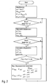
- the adaptation unit 9 then adapts the control parameters k1, k2 in the context of an adaptation method, which is illustrated in FIG. 2 in the form of a flowchart and will be described below.
- the values for the transmission ratio ⁇ , the setpoint value, are first of all ⁇ p should be initialized for the pressure difference across the metering pump 2 and the starting values k1 old and k2 old for the control parameters k1 and k2, the specifications being based on assumptions about the transmission ratio ⁇ .
- the adaptation unit 9 measures via the two pressure sensors 8, 10 the pressure p V1 upstream of the metering pump 2 and the pressure p H1 downstream of the metering pump 2. In addition, the adaptation unit also detects the ink quantity F m1 in this first operating point.
- the values p V1 , p V2 , and F m1 are available anyway in the controller and therefore do not need to be additionally measured.
- the absolute value of the difference F m1 -F m2 of the measured quantities of color is formed in the two operating points used for adaptation and compared with a minimum value. If the distance thus formed between the two operating points is too small, the second operating point is discarded.
- the control unit 7 then operates with the optimized values k1 NEW and k2 NEW of the control parameters, wherein the adaptation of the control parameters k1, k2 shown in FIG. 2 is continuously repeated during the coating operation in order to optimize the control behavior of the control unit 7 and to achieve the pressure difference .DELTA.p over the metering pump 2, the predetermined target value .DELTA.P target as precisely as possible.
- k2 NEW p H ⁇ 1 + ⁇ ⁇ p ⁇ ) - ( p H ⁇ 2 + ⁇ ⁇ p ⁇ ⁇ ⁇ p H ⁇ 1 - p H ⁇ 2
Abstract
Description
Die Erfindung betrifft eine Beschichtungsanlage zur Beschichtung von Bauteilen mit einem Beschichtungsmittel, insbesondere eine Lackieranlage zur Lackierung von Kraftfahrzeugkarosserieteilen sowie ein zugehöriges Betriebsverfahren gemäß den nebengeordneten Ansprüchen.The invention relates to a coating installation for coating components with a coating agent, in particular a painting installation for painting motor vehicle body parts and an associated operating method according to the independent claims.
Aus
Nachteilig an der vorstehend beschriebenen bekannten Beschichtungsanlage ist jedoch der Bauteilverschleiß der Dosierpumpe und des Farbdruckreglers, was zu einer geringen Standzeit dieser Bauteile führt. Dies gilt insbesondere für den Farbdruckregler, dessen Dichtring nach einer gewissen Betriebsdauer sehr starke Auswaschungen aufweist.A disadvantage of the known coating system described above, however, is the component wear of the metering pump and the color pressure regulator, resulting in a short service life of these components. This is especially true for the color pressure regulator, the sealing ring has after a certain period of operation very strong washouts.
Darüber hinaus können bei den herkömmlichen Beschichtungsanlagen Dosierungenauigkeiten auftreten, die im Extremfall zu einem Lackstromabriss führen, was sich auf den zu beschichtenden Bauteilen als Beschichtungsfehler äußert.In addition, in the conventional coating systems metering inaccuracies occur, which in extreme cases too lead to a paint stall, which manifests itself as a coating error on the components to be coated.
Aus
Eine weitere Beschichtungsanlage ist aus
Aus
Ferner sind aus
Der Erfindung liegt deshalb die Aufgabe zugrunde, die eingangs beschriebene bekannte Beschichtungsanlage entsprechend zu verbessern.The invention is therefore based on the object to improve the known coating system described above accordingly.
Diese Aufgabe wird durch eine Beschichtungsanlage und ein zugehöriges Betriebsverfahren gemäß den nebengeordneten Ansprüchen gelöst.This object is achieved by a coating system and an associated operating method according to the independent claims.
Die Erfindung beruht auf der technischen Erkenntnis, dass die Bauteilbelastung der Dosierpumpe und des Farbdruckreglers bei der eingangs beschriebenen bekannten Beschichtungsanlage dadurch verursacht wird, dass die über der Dosierpumpe abfallende Druckdifferenz während des Beschichtungsbetriebs stark schwankt. Dies führt bei einer großen positiven Druckdifferenz (d.h. der Druck vor der Dosierpumpe ist größer als der Druck hinter der Dosierpumpe) zu einer höheren Ausflussrate bei kleinen Volumenstromänderungen (sogenannten "Brushes") als erwünscht, was durch einen Pumpenschlupf verursacht wird. Bei einer negativen Druckdifferenz (d.h. der Druck vor der Dosierpumpe ist kleiner als der Druck hinter der Dosierpumpe) führen die Schwankungen der Druckdifferenz dagegen zu einer Unterversorgung des benötigten Lackvolumens, was im schlimmsten Fall die störenden Lackstromabrisse verursacht. Darüber hinaus tragen die Schwankungen der Druckdifferenz über der Dosierpumpe auch zu der unerwünschten mechanischen Belastung der Dosierpumpe und des Farbdruckreglers bei.The invention is based on the technical knowledge that the component load of the metering pump and the color pressure regulator in the known coating system described above is caused by the fact that the falling over the metering pressure difference fluctuates greatly during the coating operation. This results in a high positive pressure differential (i.e., the pressure before the metering pump is greater than the pressure behind the metering pump) to a higher outflow rate with small volume changes (so-called "brushes") than desired, which is caused by pump slippage. On the other hand, with a negative pressure difference (i.e., the pressure in front of the metering pump is less than the pressure behind the metering pump), the variations in the pressure difference result in a shortage of the required paint volume, which in the worst case causes the troublesome paint stalls. In addition, the variations in the pressure difference across the metering pump also contribute to the unwanted mechanical loading of the metering pump and the color pressure regulator.
Die Druckdifferenz über der Dosierpumpe und damit die störenden Dosierungenauigkeiten und mechanischen Belastungen werden jedoch nicht nur durch die schwankende Menge des abgegebenen Beschichtungsmittels beeinflusst. Vielmehr ändert sich die Druckdifferenz auch bei einem Wechsel zu einem Beschichtungsmittel mit einer anderen Viskosität oder bei einem Einbau eines anderen Farbdruckreglers mit einem anderen Druckübersetzungsverhältnis.However, the pressure difference across the metering pump and thus the disturbing metering inaccuracies and mechanical loads are not only influenced by the fluctuating amount of the dispensed coating agent. Rather, the pressure difference changes even when changing to a coating agent with a different viscosity or when installing another color pressure regulator with a different pressure transmission ratio.
Die Erfindung umfasst deshalb die allgemeine technische Lehre, den Differenzdruck über der Dosierpumpe im Beschichtungsbetrieb unabhängig von der abgegebenen Beschichtungsmittelmenge, der Viskosität des Beschichtungsmittels und/oder dem Druckübersetzungsverhältnis des eingesetzten Farbdruckreglers möglichst konstant zu halten, um die vorstehend beschriebenen negativen Auswirkungen auf die Dosiergenauigkeit und die Standzeit der eingesetzten Bauteile zu vermeiden.The invention therefore comprises the general technical teaching, the differential pressure across the metering pump in the coating operation regardless of the amount of coating agent delivered, the viscosity of the coating composition and / or the pressure transmission ratio of the color pressure regulator used to keep as constant as possible in order to avoid the negative effects on the dosing accuracy and the service life of the components used described above.
Die erfindungsgemäße Beschichtungsanlage weist deshalb eine Steuer- bzw. Regeleinheit auf, die den Druckregler ansteuert und als Steuer- bzw. Regelgröße die Druckdifferenz über der Dosierpumpe unabhängig von der Fördermenge der Dosierpumpe auf einen im Wesentlichen konstanten Soll-Wert einstellt. Bei der Erfindung ist also die Druckdifferenz über der Dosierpumpe die Steuer- bzw. Regelgröße, wohingegen bei dem eingangs beschriebenen Stand der Technik der Ausgangsdruck des Druckreglers bzw. die Farbdurchflussmenge geregelt wurden.Therefore, the coating system according to the invention has a control unit which controls the pressure regulator and sets as a control or control variable, the pressure difference across the metering pump regardless of the delivery rate of the metering pump to a substantially constant desired value. In the invention, therefore, the pressure difference across the metering pump is the control or control variable, whereas in the described prior art, the output pressure of the pressure regulator or the ink flow rate were regulated.
Vorzugsweise erfolgt die Konstanthaltung des Differenzdrucks über der Dosierpumpe durch eine Steuereinheit, d.h. ohne eine Messung und Rückkopplung des Ist-Wertes der Druckdifferenz. Vorteilhaft an einer Steuerung der Druckdifferenz im Gegensatz zu einer Regelung der Druckdifferenz ist die fehlende Schwingungsneigung, die einfache technische Realisierung, die schnelle Reaktion auf Drucksprünge und Farbmengenänderungen und die Ermöglichung einer Kompensation der Totzeit des Proportionalventils.Preferably, the differential pressure across the metering pump is kept constant by a control unit, i. without a measurement and feedback of the actual value of the pressure difference. An advantage of a control of the pressure difference in contrast to a regulation of the pressure difference is the lack of tendency to oscillate, the simple technical realization, the rapid response to pressure jumps and color quantity changes and the possibility of compensation for the dead time of the proportional valve.
Es besteht jedoch im Rahmen der Erfindung auch die Möglichkeit, die Druckdifferenz über der Dosierpumpe mittels einer Regeleinheit zu regeln. Dies bedeutet, dass der Ist-Wert der Druckdifferenz über der Dosierpumpe gemessen und einem Regler zugeführt wird, der dann den Farbdruckregler entsprechend ansteuert, um die Druckdifferenz über der Dosierpumpe auf den gewünschten Wert einzuregeln. Bei einem solchen Regler kann es sich beispielsweise um einen herkömmlichen PID-Regler handeln, jedoch sind im Rahmen der Erfindung auch andere Reglertypen einsetzbar.However, it is within the scope of the invention also possible to regulate the pressure difference across the metering pump by means of a control unit. This means that the actual value of the pressure difference across the metering pump is measured and fed to a regulator, which then controls the color pressure regulator accordingly, in order to regulate the pressure difference across the metering pump to the desired value. In such a controller can For example, it may be a conventional PID controller, but other types of controllers can be used within the scope of the invention.
Ferner besteht im Rahmen der Erfindung auch die Möglichkeit, eine Regelung mit einer Steuerung zu kombinieren, indem die Regelung beispielsweise mit einer Vorsteuerung überlagert wird, was die Vorteile der Regelung einerseits und der Steuerung andererseits miteinander verbindet.Furthermore, within the scope of the invention, it is also possible to combine a control with a control by superimposing the control, for example, with a pilot control, which connects the advantages of the control, on the one hand, and the control, on the other hand.
In dem bevorzugten Ausführungsbeispiel der Erfindung wird jedoch zur Konstanthaltung der Druckdifferenz über der Dosierpumpe eine sogenannte Parameter-Steuerung eingesetzt, d.h. keine Regelung, so dass der Ist-Wert der Druckdifferenz über der Dosierpumpe nicht gemessen werden muss.In the preferred embodiment of the invention, however, so-called parameter control is used to keep the pressure difference across the metering pump constant. No regulation, so that the actual value of the pressure difference across the metering pump does not have to be measured.
Hierzu ist in dem bevorzugten Ausführungsbeispiel der Erfindung ein erster Drucksensor vorgesehen, der den Beschichtungsmitteldruck stromabwärts hinter der Dosierpumpe, d.h. am Ausgang der Dosierpumpe misst. Der gemessene Beschichtungsmitteldruck am Ausgang der Dosierpumpe wird dann der Steuereinheit zugeführt, die den Druckregler in Abhängigkeit von dem stromabwärts hinter der Dosierpumpe gemessenen Beschichtungsmitteldruck entsprechend einem vorgegebenen Steuerverhalten so ansteuert, dass die Druckdifferenz über der Dosierpumpe den vorgegebenen Soll-Wert annimmt und konstant hält.To this end, in the preferred embodiment of the invention, a first pressure sensor is provided which controls the coating agent pressure downstream of the metering pump, i. at the outlet of the metering pump. The measured coating agent pressure at the outlet of the metering pump is then fed to the control unit, which controls the pressure regulator as a function of the coating agent pressure measured downstream of the metering pump in accordance with a predetermined control behavior such that the pressure difference across the metering pump assumes the predetermined desired value and keeps it constant.
Die Ansteuerung des Druckreglers durch die Steuereinheit erfolgt in dem bevorzugten Ausführungsbeispiel der Erfindung mittelbar über ein zwischengeschaltetes Proportionalventil, was an sich aus dem eingangs erwähnten Stand der Technik bekannt ist. Das Proportionalventil wird hierbei von der Steuereinheit elektrisch angesteuert und steuert seinerseits den Farbdruckregler pneumatisch an.The control of the pressure regulator by the control unit takes place in the preferred embodiment of the invention indirectly via an intermediate proportional valve, which is known per se from the above-mentioned prior art. The proportional valve is electrically controlled by the control unit and in turn controls the color pressure regulator pneumatically.
Vorzugsweise ist das Steuerverhalten der Steuereinheit hierbei durch eine im Wesentlichen lineare Steuerkennlinie vorgegeben, wobei die Steuerkennlinie den Zusammenhang zwischen dem am Ausgang der Dosierpumpe gemessenen Druck und der daraus resultierenden Ansteuergröße für den Druckregler bzw. das zwischengeschaltete Proportionalventil definiert. Die lineare Steuerkennlinie weist hierbei einen vorgegebenen Achsenabschnittswert und eine vorgegebene Steigung auf, wobei der Achsenabschnittswert vorzugsweise in Abhängigkeit von dem gewünschten Soll-Wert der Druckdifferenz über der Dosierpumpe und dem tatsächlichen Druckübersetzungsverhältnis des Systems aus dem Proportionalventil und dem Farbdruckregler festgelegt wird, während die Steigung der Steuerkennlinie vorzugsweise in Abhängigkeit von dem Übersetzungsverhältnis des Systems aus dem Proportionalventil und dem Druckregler vorgegeben wird. Für die Steuerkennlinie gilt also vorzugsweise: ![]()
- kd:
- Ansteuerungsgröße zur Ansteuerung des Proportionalventils
- PH:
- gemessener Druck hinter der Dosierpumpe
- k1:
- Achsenabschnittswert der Steuerkennlinie
- k2:
- Steigung der Steuerkennlinie.
- kd:
- Control variable for controlling the proportional valve
- P H :
- measured pressure behind the dosing pump
- k1:
- Axis section value of the control characteristic
- k2:
- Slope of the control characteristic.
Die Steuerparameter k1 und k2 der Steuerkennlinie sind hierbei wie folgt eingestellt, um die gewünschte Druckdifferenz über der Dosierpumpe einzustellen: 

- ΔpSoll:
- Soll-Wert der Druckdifferenz über der Dosierpumpe,
- η:
- Übersetzungsverhältnis des Systems aus dem Druckregler und der vorgeschalteten Proportionalventil.
- Δp target :
- Target value of the pressure difference across the dosing pump,
- η:
- Ratio of the system from the pressure regulator and the upstream proportional valve.
Bei einer Einstellung der Steuerparameter k1, k2 auf die vorstehend genannten Werte stellt sich unabhängig von der Fördermenge die gewünschte Druckdifferenz über der Dosierpumpe ein, wie sich aus folgender Formel ergibt: 
Die exakte Einstellung der optimalen Steuerparameter K1, K2 setzt jedoch die Kenntnis des Übersetzungsverhältnisses η des Systems aus dem Proportionalventil und dem Druckregler voraus. Bei einem Austausch des Druckreglers oder bei einem Wechsel zu einem Beschichtungsmittel mit einer anderen Viskosität ist das Übersetzungsverhältnis η jedoch nicht bekannt, so dass die Steuerparameter k1, k2 bestimmt werden müssen. Vorzugsweise erfolgt die Bestimmung der Steuerparameter k1 und k2 im Rahmen einer Adaption, wobei auch der Beschichtungsmitteldruck stromaufwärts vor der Dosierpumpe gemessen und ausgewertet wird. Die Adaption des Steuerverhaltens erfolgt dann durch eine Adaptionseinheit, die eingangsseitig mit den beiden Drucksensoren verbunden ist und das Steuerverhalten der Steuereinheit in Abhängigkeit von dem gemessenen Beschichtungsmitteldruck stromaufwärts vor der Dosierpumpe und dem gemessenen Beschichtungsmitteldruck stromabwärts hinter der Dosierpumpe adaptiert.The exact setting of the optimal control parameters K1, K2, however, presupposes the knowledge of the transmission ratio η of the system from the proportional valve and the pressure regulator. When replacing the pressure regulator or when changing to a coating agent with a different viscosity, the transmission ratio η is not known, so that the control parameters k1, k2 must be determined. Preferably, the determination of the control parameters k1 and k2 takes place in the context of an adaptation, whereby the coating agent pressure upstream of the metering pump is also measured and evaluated. The adaptation of the control behavior then takes place by means of an adaptation unit, which is connected on the input side to the two pressure sensors and adapts the control behavior of the control unit downstream of the metering pump upstream of the metering pump and the measured coating agent pressure downstream of the metering pump as a function of the measured coating agent pressure.
Vorzugsweise erfolgt die Adaption des Steuerverhaltens der Steuereinheit iterativ und/oder rekursiv. Eine iterative Adaption des Steuerverhaltens bedeutet, dass das Steuerverhalten nacheinander in mehreren Schritten dem optimalen Steuerverhalten angenähert wird, das erforderlich ist, um die Druckdifferenz über der Dosierpumpe konstant zu halten. Eine rekursive Adaption in dem erfindungsgemäßen Sinne bedeutet, dass aus dem aktuellen Steuerverhalten der Steuereinheit jeweils ein verbessertes Steuerverhalten berechnet wird.The adaptation of the control behavior of the control unit preferably takes place iteratively and / or recursively. An iterative adaptation of the control behavior means that the control behavior is sequentially approximated in several steps to the optimal control behavior that is required to keep the pressure difference across the metering pump constant. A recursive adaptation in the sense according to the invention means that an improved control behavior is calculated in each case from the current control behavior of the control unit.
Die Adaption des Steuerverhaltens der Steuereinheit kann während des normalen Beschichtungsbetriebs oder in separaten Adaptionsphasen erfolgen. Darüber hinaus kann die Adaption während des normalen Beschichtungsbetriebs laufend oder in bestimmten Zeitabständen erfolgen.The adaptation of the control behavior of the control unit can take place during the normal coating operation or in separate adaptation phases. In addition, the adaptation during the normal coating operation can be done continuously or at certain intervals.
Andere vorteilhafte Weiterbildungen der Erfindung sind in den Unteransprüchen gekennzeichnet oder werden nachstehend zusammen mit der Beschreibung des bevorzugten Ausführungsbeispiels der Erfindung anhand der Figuren näher erläutert. Es zeigen:
Figur 1- eine schematische Darstellung einer erfindungsgemäßen Beschichtungsanlage sowie
Figur 2- das erfindungsgemäße Adaptionsverfahren zur Anpassung des Steuerverhaltens in Form eines Flussdiagramms.
- FIG. 1
- a schematic representation of a coating system according to the invention and
- FIG. 2
- the adaptation method according to the invention for adjusting the control behavior in the form of a flow chart.
Die in Figur 1 schematisch dargestellte erfindungsgemäße Beschichtungsanlage stimmt teilweise mit dem eingangs beschriebenen Stand der Technik gemäß
Der Farbdruckregler 3 kann in herkömmlicher Weise ausgebildet sein, was beispielsweise in
Im Betrieb regelt der Farbdruckregler 3 am Eingang der Dosierpumpe 2 einen Farbdruck pv in Abhängigkeit von einem Steuerdruck pSTEUER, der dem Farbdruckregler 3 durch ein Proportionalventil 5 zugeführt wird, wobei das Proportionalventil 5 an eine Steuerluftleitung 6 angeschlossen ist, die einen Steuerluftdruck pLUFT≈10 bar bereit stellt.In operation, the color pressure regulator 3 at the input of the
Das Proportionalventil 5 wird von einer Steuereinheit 7 mit einem elektrischen Steuersignal kd angesteuert, wobei das System aus dem Proportionalventil 5 und dem Farbdruckregler 3 ein Übersetzungsverhältnis η=pv/kd aufweist, d.h. bei einer Ansteuerung des Proportionalventils 5 mit dem elektrischen Steuersignal kd stellt sich am Ausgang des Farbdruckreglers 3 ein Beschichtungsmitteldruck pv=kd·η ein.The
Bei der Ansteuerung des Proportionalventils 5 berücksichtigt die Steuereinheit den Beschichtungsmitteldruck pH am Ausgang der Dosierpumpe 2, wobei der Druck pH von einem Drucksensor 8 gemessen wird. Die Ansteuerung des Proportionalventils 5 durch die Steuereinheit 7 erfolgt dann entsprechend der folgenden linearen Steuerkennlinie: ![]()
![]()
Die Steuerparameter k1 und k2 werden dabei wie folgt eingestellt: 

Bei einer solchen optimalen Einstellung der Steuerparameter k1, k2 stellt sich dann über der Dosierpumpe 2 die gewünschte Druckdifferenz ΔpSoll ein, wie aus folgender Herleitung deutlich wird: 
Die Ermittlung der optimalen Werte der Steuerparameter k1 und k2 setzt jedoch die Kenntnis des Übersetzungsverhältnisses η des Systems aus dem Proportionalventil 5 und dem Farbdruckregler 3. Nach einem Austausch des Farbdruckreglers 3 durch einen anderen Farbdruckregler mit einem anderen Druckübersetzungsverhältnis müssen die Steuerparameter k1, k2 deshalb an das veränderte Druckübersetzungsverhältnis des Farbdruckreglers 3 angepasst werden. Auch bei einem Wechsel des eingesetzten Beschichtungsmittels und einer dadurch bedingten Veränderung der Viskosität des Beschichtungsmittels ändert sich das Übersetzungsverhältnis η, was ebenfalls eine Anpassung der Steuerparameter k1, k2 erforderlich macht.However, the determination of the optimum values of the control parameters k1 and k2 sets the knowledge of the transmission ratio η of the system from the
Die erfindungsgemäße Beschichtungsanlage weist deshalb eine Adaptionseinheit 9 auf, die mit dem Drucksensor 8 verbunden ist und darüber hinaus über einen weiteren Drucksensor 10 den Beschichtungsmitteldruck pv vor der Dosierpumpe 2 misst. Die Adaptionseinheit 9 adaptiert dann die Steuerparameter k1, k2 im Rahmen eines Adaptionsverfahrens, das in Figur 2 in Form eines Flussdiagramms dargestellt ist und nachfolgend beschrieben wird.The coating installation according to the invention therefore has an
Bei der erstmaligen Adaption der Steuerparameter werden zunächst die Werte für das Übersetzungsverhältnis η, den Soll-Wert Δpsoll für die Druckdifferenz über der Dosierpumpe 2 und die Startwerte k1Alt und k2Alt für die Steuerparameter k1 und k2 initialisiert, wobei die Vorgaben auf Vermutungen über das Übersetzungsverhältnis η beruhen.When first adapting the control parameters, the values for the transmission ratio η, the setpoint value, are first of all Δp should be initialized for the pressure difference across the
Anschließend wird ein sogenannter Brush abgewartet, der länger als eine Sekunde dauert. Dabei handelt es sich um eine Volumenstromänderung in dem abgegebenen Beschichtungsmittelstrom, der auf einer Öffnung der Hauptnadel des Zerstäubers 1 beruht. Die Berücksichtigung nur relativ lang andauernder Brushes mit einer Zeitdauer von mehr als 1 Sekunde ist sinnvoll, da die Zeitdauer kürzerer Brushes nicht ausreicht, um Einschwingvorgänge abklingen zu lassen.Subsequently, a so-called Brush is waited, which lasts longer than one second. This is a volume flow change in the dispensed coating medium flow, which is based on an opening of the main needle of the
Anschließend misst die Adaptionseinheit 9 über die beiden Drucksensoren 8, 10 den Druck pV1 vor der Dosierpumpe 2 und den Druck pH1 hinter der Dosierpumpe 2. Darüber hinaus erfasst die Adaptionseinheit in diesem ersten Betriebspunkt auch die Farbmenge Fm1. Die Werte pV1, pV2, und Fm1 stehen hierbei in der Steuerung ohnehin zur Verfügung und müssen deshalb nicht zusätzlich gemessen werden.Subsequently, the
Anschließend wird der nächste Brush abgewartet, der länger als eine Sekunde dauert und deshalb nicht mehr von Einschwingvorgängen betroffen ist.Then wait for the next brush, which lasts longer than one second and is therefore no longer affected by transients.
In diesem zweiten Betriebspunkt werden dann wieder die Werte PV2, PH2 und Fm2 für den Druck pV vor der Dosierpumpe 2, den Druck pH hinter der Dosierpumpe 2 und die Farbmenge Fm aus der Steuerung ausgelesen und abgespeichert. Auch hierbei kann also ausgenutzt werden, dass die Werte pV2, pH2 und Fm2 ohnehin zur Verfügung stehen und deshalb nicht zusätzlich gemessen werden müssen.In this second operating point, the values P V2 , P H2 and F m2 for the pressure p V upstream of the
Dann wird geprüft, ob die beiden Betriebspunkte hinreichend weit voneinander entfernt sind, um eine aussagekräftige Messung zu ermöglichen. Hierzu wird der Absolutwert der Differenz Fm1-Fm2 der gemessenen Farbmengen in den beiden zur Adaption herangezogenen Betriebspunkte gebildet und mit einem Minimalwert verglichen. Falls der so gebildete Abstand zwischen den beiden Betriebspunkten zu klein ist, wird der zweite Betriebspunkt verworfen.Then it is checked whether the two operating points are sufficiently far apart to allow a meaningful measurement. For this purpose, the absolute value of the difference F m1 -F m2 of the measured quantities of color is formed in the two operating points used for adaptation and compared with a minimum value. If the distance thus formed between the two operating points is too small, the second operating point is discarded.
Andernfalls werden dann aus den bisherigen Werten k1Alt, k2Alt der Steuerparameter optimierte Werte k1NEU, k2NEU nach folgenden Formeln berechnet: 

Anschließend arbeitet die Steuereinheit 7 dann mit den optimierten Werten k1NEU und k2NEU der Steuerparameter, wobei die in Figur 2 dargestellte Adaption der Steuerparameter k1, k2 während des Beschichtungsbetriebs laufend wiederholt wird, um das Steuerverhalten der Steuereinheit 7 zu optimieren und zu erreichen, dass die Druckdifferenz Δp über der Dosierpumpe 2 den vorgegebenen Soll-Wert ΔpSoll möglichst genau einhält.The
Die vorstehend genannten Formeln zur Adaption der Steuerparameter k1, k2 ergeben sich aus der folgenden mathematischphysikalischen Herleitung.The above-mentioned formulas for adapting the control parameters k1, k2 result from the following mathematical-physical derivation.
Zunächst wird das Verhalten der Beschichtungsanlage durch folgende Gleichungen beschrieben: 


- kd:
- Ansteuerungsgröße zur Ansteuerung des
Proportionalventils 5, - pV
- gemessener Druck vor der Dosierpumpe 2,
- pH:
- gemessener Druck hinter der Dosierpumpe 2,
- k1:
- Achsenabschnittswert der Steuerkennlinie,
- k2:
- Steigung der Steuerkennlinie,
- Δpsoll:
- Soll-Wert der Druckdifferenz über der Dosierpumpe 2,
- Δp:
- Ist-Wert der Druckdifferenz über der Dosierpumpe 2,
- η:
- Übersetzungsverhältnis des Systems aus dem Druckregler 3 und der vorgeschalteten Proportionalventil 5.
- kd:
- Control variable for controlling the
proportional valve 5, - p V
- measured pressure before the
metering pump 2, - p H :
- measured pressure behind the
metering pump 2, - k1:
- Intercept value of the control characteristic,
- k2:
- Slope of the control characteristic,
- Δp should :
- Target value of the pressure difference across the
metering pump 2, - Ap:
- Actual value of the pressure difference across the
metering pump 2, - η:
- Ratio of the system of the pressure regulator 3 and the upstream proportional valve. 5
Aus den Gleichungen (1) und (2) folgt: ![]()
![]()
Betrachtet man nun zwei Betriebspunkte mit unterschiedlichen Farbmengen Fm1, Fm2 und verschiedenen Beschichtungsmitteldrücken pV1, pV2, pH1 und pH2 vor bzw. hinter der Dosierpumpe, so gilt gemäß Gleichung (4) für diese beiden Betriebspunkte jeweils: ![]()
![]()
![]()
![]()
Aus den Gleichungen (5) und (6) folgt dann für den Steuerparameter k2: 
Für den alten, nicht optimierten Wert k2Alt des Steuerparameters k2 gilt dann unmittelbar: 
Für den neuen, optimierten Wert k2Neu des Steuerparameters k2 gilt dann unter Berücksichtigung der bei optimalem Steuerverhalten erfüllten Gleichung (3): 
Aus den Gleichungen (8) und (9) folgt dann die Adaptionsformel für die Adaption des Steuerparameters k2: 
Im Folgenden wird nun die Herleitung der Adaptionsformel für den Steuerparameter k1 beschrieben. Aus den Gleichungen (1), (2) und (3) folgt: 
Setzt man Gleichung (6) in Gleichung (11) ein, so erhält man für den alten, nicht optimierten Wert k1Alt des Steuerparameters k1 im Betriebspunkt 1 mit pV1, pH1 und Fm1: 
Für den neuen adaptierten Optimalwert k1Neu muss dagegen gelten: 
Aus den Gleichungen (12) und (13) folgt dann schließlich die Adaptionsformel für die Adaption des Steuerparameters k1: 
Die Erfindung ist nicht auf das vorstehend beschriebene bevorzugte Ausführungsbeispiel beschränkt. Vielmehr ist eine Vielzahl von Varianten und Abwandlungen möglich, die ebenfalls von dem Erfindungsgedanken Gebrauch machen und deshalb in den Schutzbereich fallen.The invention is not limited to the preferred embodiment described above. Rather, a variety of variants and modifications is possible, which also make use of the inventive idea and therefore fall within the scope.
- 11
- Zerstäuberatomizer
- 22
- Dosierpumpemetering
- 33
- FarbdruckreglerPaint pressure regulator
- 44
- Farbleitungpaint line
- 55
- Proportionalventilproportional valve
- 66
- SteuerluftleitungControl air line
- 77
- Steuereinheitcontrol unit
- 88th
- Drucksensorpressure sensor
- 99
- Adaptionseinheitadaptation unit
- 1010
- Drucksensorpressure sensor
Claims (25)
gekennzeichnet durch
marked by
gekennzeichnet durch
marked by
gekennzeichnet durch folgenden Schritt:
characterized by the following step:
Applications Claiming Priority (1)
| Application Number | Priority Date | Filing Date | Title |
|---|---|---|---|
| DE102005042336A DE102005042336A1 (en) | 2005-09-06 | 2005-09-06 | Coating plant e.g. paint shop, for painting motor vehicle-body parts, has control unit provided for controlling color pressure controller and adjusting pressure difference at pump to constant value independent of discharge quantity of pump |
Publications (2)
| Publication Number | Publication Date |
|---|---|
| EP1764159A1 true EP1764159A1 (en) | 2007-03-21 |
| EP1764159B1 EP1764159B1 (en) | 2009-07-29 |
Family
ID=37668215
Family Applications (1)
| Application Number | Title | Priority Date | Filing Date |
|---|---|---|---|
| EP06017809A Active EP1764159B1 (en) | 2005-09-06 | 2006-08-25 | Coating device and method |
Country Status (4)
| Country | Link |
|---|---|
| EP (1) | EP1764159B1 (en) |
| AT (1) | ATE437702T1 (en) |
| DE (2) | DE102005042336A1 (en) |
| ES (1) | ES2329705T3 (en) |
Cited By (2)
| Publication number | Priority date | Publication date | Assignee | Title |
|---|---|---|---|---|
| DE102007053073A1 (en) * | 2007-11-07 | 2009-06-04 | Dürr Systems GmbH | application system |
| CN112188934A (en) * | 2018-07-02 | 2021-01-05 | 得立鼎工业株式会社 | Paint supply system |
Citations (11)
| Publication number | Priority date | Publication date | Assignee | Title |
|---|---|---|---|---|
| US3584977A (en) | 1969-04-17 | 1971-06-15 | Du Pont | Process for metering liquid through serially connected pumps |
| JPS63111963A (en) * | 1986-10-31 | 1988-05-17 | Trinity Ind Corp | Coating agent feeder |
| JPH0929147A (en) * | 1995-07-19 | 1997-02-04 | Trinity Ind Corp | Paint feeder |
| WO1998035761A1 (en) * | 1997-02-17 | 1998-08-20 | Abb Flexible Automation A/S | Method and device for feeding a controlled volume flow of liquid to a spray nozzle |
| EP0697317B1 (en) | 1994-08-16 | 1999-03-24 | WABCO GmbH | Method and device for pressure control |
| EP1287900A2 (en) | 2001-08-30 | 2003-03-05 | Dürr Systems GmbH | Coating installation with a closed loop control sytem |
| EP1376289A1 (en) | 2002-06-25 | 2004-01-02 | Dürr Systems GmbH | Pressure control member |
| DE69814532T2 (en) | 1997-07-04 | 2004-04-01 | Kawasaki Jukogyo K.K., Kobe | Device for controlling the supply of a viscous fluid |
| EP1437520A2 (en) | 2003-01-13 | 2004-07-14 | Siemens Aktiengesellschaft | Method of controlling an automatically actuated clutch |
| EP1481736A2 (en) * | 2003-05-27 | 2004-12-01 | Dürr Systems GmbH | Supply device for a painting installation |
| WO2005072881A1 (en) | 2004-01-29 | 2005-08-11 | Gunter Prediger | Device and method for producing resin coatings |
-
2005
- 2005-09-06 DE DE102005042336A patent/DE102005042336A1/en not_active Withdrawn
-
2006
- 2006-08-25 EP EP06017809A patent/EP1764159B1/en active Active
- 2006-08-25 ES ES06017809T patent/ES2329705T3/en active Active
- 2006-08-25 DE DE502006004357T patent/DE502006004357D1/en active Active
- 2006-08-25 AT AT06017809T patent/ATE437702T1/en not_active IP Right Cessation
Patent Citations (11)
| Publication number | Priority date | Publication date | Assignee | Title |
|---|---|---|---|---|
| US3584977A (en) | 1969-04-17 | 1971-06-15 | Du Pont | Process for metering liquid through serially connected pumps |
| JPS63111963A (en) * | 1986-10-31 | 1988-05-17 | Trinity Ind Corp | Coating agent feeder |
| EP0697317B1 (en) | 1994-08-16 | 1999-03-24 | WABCO GmbH | Method and device for pressure control |
| JPH0929147A (en) * | 1995-07-19 | 1997-02-04 | Trinity Ind Corp | Paint feeder |
| WO1998035761A1 (en) * | 1997-02-17 | 1998-08-20 | Abb Flexible Automation A/S | Method and device for feeding a controlled volume flow of liquid to a spray nozzle |
| DE69814532T2 (en) | 1997-07-04 | 2004-04-01 | Kawasaki Jukogyo K.K., Kobe | Device for controlling the supply of a viscous fluid |
| EP1287900A2 (en) | 2001-08-30 | 2003-03-05 | Dürr Systems GmbH | Coating installation with a closed loop control sytem |
| EP1376289A1 (en) | 2002-06-25 | 2004-01-02 | Dürr Systems GmbH | Pressure control member |
| EP1437520A2 (en) | 2003-01-13 | 2004-07-14 | Siemens Aktiengesellschaft | Method of controlling an automatically actuated clutch |
| EP1481736A2 (en) * | 2003-05-27 | 2004-12-01 | Dürr Systems GmbH | Supply device for a painting installation |
| WO2005072881A1 (en) | 2004-01-29 | 2005-08-11 | Gunter Prediger | Device and method for producing resin coatings |
Non-Patent Citations (1)
| Title |
|---|
| TECHNISCHES HANDBUCH FARBMENGEN- REGELUNG, 1994, pages 32 |
Cited By (3)
| Publication number | Priority date | Publication date | Assignee | Title |
|---|---|---|---|---|
| DE102007053073A1 (en) * | 2007-11-07 | 2009-06-04 | Dürr Systems GmbH | application system |
| CN112188934A (en) * | 2018-07-02 | 2021-01-05 | 得立鼎工业株式会社 | Paint supply system |
| CN112188934B (en) * | 2018-07-02 | 2022-04-26 | 得立鼎工业株式会社 | Paint supply system |
Also Published As
| Publication number | Publication date |
|---|---|
| DE502006004357D1 (en) | 2009-09-10 |
| ATE437702T1 (en) | 2009-08-15 |
| ES2329705T3 (en) | 2009-11-30 |
| EP1764159B1 (en) | 2009-07-29 |
| DE102005042336A1 (en) | 2007-03-15 |
Similar Documents
| Publication | Publication Date | Title |
|---|---|---|
| EP1929253B1 (en) | Method for controlling a dosing apparatus for liquid or pasty media | |
| EP2855002B1 (en) | Method and device for mixing at least two liquid components | |
| EP2039492B1 (en) | Method of extrusion | |
| DE102013015313A1 (en) | Application system and corresponding application method | |
| WO2000010726A1 (en) | Powder spray coating device | |
| DE60217191T2 (en) | METHOD FOR CALIBRATING A LIQUID DOSING DEVICE | |
| EP1764159B1 (en) | Coating device and method | |
| EP1481736B1 (en) | Supply device for a painting installation | |
| DE19838279A1 (en) | Powder coating system has an injector stage with air supply controlled by restrictor valves that are coupled to a processor | |
| EP0644025A1 (en) | Method for mixing components and device for executing the method | |
| EP3424679B1 (en) | Filtering device and method for operating the same | |
| DE3100322A1 (en) | Process and appliance for preparing a homogeneous mixture | |
| WO2000010727A1 (en) | Powder coating device | |
| DE102015120381A1 (en) | Automatic delivery pressure control | |
| EP1337451B1 (en) | Method for the pneumatic transportation of bulk material | |
| EP3212914B1 (en) | Method for calibrating a fluid pump arrangement | |
| EP3711864B1 (en) | Method for controlling the supply pressure in a circulation system for a coating device and circulation system | |
| DE202019000576U1 (en) | Device for applying medium to high viscosity liquid materials | |
| EP2511228B1 (en) | Removal device and control for same | |
| AT524422B1 (en) | Device for dosing small volume flows of a viscous medium from a high-pressure line | |
| EP0515765B1 (en) | Evaporating device and method for its use | |
| DE102018214070B4 (en) | Method and device for applying medium to high viscosity materials | |
| WO2004051200A1 (en) | Method for after-run amount regulation in filling units | |
| DE10125863A1 (en) | Commercial gas flow production involves taking mixed gas from buffer, and compensating for deviations in flow from surplus gas flow, to maintain constant mixture ratio | |
| DE102020132165A1 (en) | Self-regulating valve |
Legal Events
| Date | Code | Title | Description |
|---|---|---|---|
| PUAI | Public reference made under article 153(3) epc to a published international application that has entered the european phase |
Free format text: ORIGINAL CODE: 0009012 |
|
| AK | Designated contracting states |
Kind code of ref document: A1 Designated state(s): AT BE BG CH CY CZ DE DK EE ES FI FR GB GR HU IE IS IT LI LT LU LV MC NL PL PT RO SE SI SK TR |
|
| AX | Request for extension of the european patent |
Extension state: AL BA HR MK YU |
|
| 17P | Request for examination filed |
Effective date: 20070404 |
|
| 17Q | First examination report despatched |
Effective date: 20070823 |
|
| AKX | Designation fees paid |
Designated state(s): AT BE BG CH CY CZ DE DK EE ES FI FR GB GR HU IE IS IT LI LT LU LV MC NL PL PT RO SE SI SK TR |
|
| GRAP | Despatch of communication of intention to grant a patent |
Free format text: ORIGINAL CODE: EPIDOSNIGR1 |
|
| GRAS | Grant fee paid |
Free format text: ORIGINAL CODE: EPIDOSNIGR3 |
|
| GRAA | (expected) grant |
Free format text: ORIGINAL CODE: 0009210 |
|
| AK | Designated contracting states |
Kind code of ref document: B1 Designated state(s): AT BE BG CH CY CZ DE DK EE ES FI FR GB GR HU IE IS IT LI LT LU LV MC NL PL PT RO SE SI SK TR |
|
| REG | Reference to a national code |
Ref country code: GB Ref legal event code: FG4D Free format text: NOT ENGLISH |
|
| REG | Reference to a national code |
Ref country code: CH Ref legal event code: EP |
|
| REG | Reference to a national code |
Ref country code: IE Ref legal event code: FG4D |
|
| REF | Corresponds to: |
Ref document number: 502006004357 Country of ref document: DE Date of ref document: 20090910 Kind code of ref document: P |
|
| REG | Reference to a national code |
Ref country code: SE Ref legal event code: TRGR |
|
| REG | Reference to a national code |
Ref country code: ES Ref legal event code: FG2A Ref document number: 2329705 Country of ref document: ES Kind code of ref document: T3 |
|
| RAP2 | Party data changed (patent owner data changed or rights of a patent transferred) |
Owner name: DUERR SYSTEMS GMBH |
|
| PG25 | Lapsed in a contracting state [announced via postgrant information from national office to epo] |
Ref country code: LT Free format text: LAPSE BECAUSE OF FAILURE TO SUBMIT A TRANSLATION OF THE DESCRIPTION OR TO PAY THE FEE WITHIN THE PRESCRIBED TIME-LIMIT Effective date: 20090729 Ref country code: IS Free format text: LAPSE BECAUSE OF FAILURE TO SUBMIT A TRANSLATION OF THE DESCRIPTION OR TO PAY THE FEE WITHIN THE PRESCRIBED TIME-LIMIT Effective date: 20091129 Ref country code: FI Free format text: LAPSE BECAUSE OF FAILURE TO SUBMIT A TRANSLATION OF THE DESCRIPTION OR TO PAY THE FEE WITHIN THE PRESCRIBED TIME-LIMIT Effective date: 20090729 |
|
| PG25 | Lapsed in a contracting state [announced via postgrant information from national office to epo] |
Ref country code: LV Free format text: LAPSE BECAUSE OF FAILURE TO SUBMIT A TRANSLATION OF THE DESCRIPTION OR TO PAY THE FEE WITHIN THE PRESCRIBED TIME-LIMIT Effective date: 20090729 Ref country code: PL Free format text: LAPSE BECAUSE OF FAILURE TO SUBMIT A TRANSLATION OF THE DESCRIPTION OR TO PAY THE FEE WITHIN THE PRESCRIBED TIME-LIMIT Effective date: 20090729 Ref country code: SI Free format text: LAPSE BECAUSE OF FAILURE TO SUBMIT A TRANSLATION OF THE DESCRIPTION OR TO PAY THE FEE WITHIN THE PRESCRIBED TIME-LIMIT Effective date: 20090729 |
|
| NLT2 | Nl: modifications (of names), taken from the european patent patent bulletin |
Owner name: DUERR SYSTEMS GMBH Effective date: 20100120 |
|
| REG | Reference to a national code |
Ref country code: IE Ref legal event code: FD4D |
|
| PG25 | Lapsed in a contracting state [announced via postgrant information from national office to epo] |
Ref country code: PT Free format text: LAPSE BECAUSE OF FAILURE TO SUBMIT A TRANSLATION OF THE DESCRIPTION OR TO PAY THE FEE WITHIN THE PRESCRIBED TIME-LIMIT Effective date: 20091129 Ref country code: MC Free format text: LAPSE BECAUSE OF NON-PAYMENT OF DUE FEES Effective date: 20090831 Ref country code: BG Free format text: LAPSE BECAUSE OF FAILURE TO SUBMIT A TRANSLATION OF THE DESCRIPTION OR TO PAY THE FEE WITHIN THE PRESCRIBED TIME-LIMIT Effective date: 20091029 |
|
| PG25 | Lapsed in a contracting state [announced via postgrant information from national office to epo] |
Ref country code: RO Free format text: LAPSE BECAUSE OF FAILURE TO SUBMIT A TRANSLATION OF THE DESCRIPTION OR TO PAY THE FEE WITHIN THE PRESCRIBED TIME-LIMIT Effective date: 20090729 Ref country code: IE Free format text: LAPSE BECAUSE OF FAILURE TO SUBMIT A TRANSLATION OF THE DESCRIPTION OR TO PAY THE FEE WITHIN THE PRESCRIBED TIME-LIMIT Effective date: 20090729 Ref country code: EE Free format text: LAPSE BECAUSE OF FAILURE TO SUBMIT A TRANSLATION OF THE DESCRIPTION OR TO PAY THE FEE WITHIN THE PRESCRIBED TIME-LIMIT Effective date: 20090729 Ref country code: DK Free format text: LAPSE BECAUSE OF FAILURE TO SUBMIT A TRANSLATION OF THE DESCRIPTION OR TO PAY THE FEE WITHIN THE PRESCRIBED TIME-LIMIT Effective date: 20090729 Ref country code: CZ Free format text: LAPSE BECAUSE OF FAILURE TO SUBMIT A TRANSLATION OF THE DESCRIPTION OR TO PAY THE FEE WITHIN THE PRESCRIBED TIME-LIMIT Effective date: 20090729 |
|
| PG25 | Lapsed in a contracting state [announced via postgrant information from national office to epo] |
Ref country code: SK Free format text: LAPSE BECAUSE OF FAILURE TO SUBMIT A TRANSLATION OF THE DESCRIPTION OR TO PAY THE FEE WITHIN THE PRESCRIBED TIME-LIMIT Effective date: 20090729 |
|
| PLBE | No opposition filed within time limit |
Free format text: ORIGINAL CODE: 0009261 |
|
| STAA | Information on the status of an ep patent application or granted ep patent |
Free format text: STATUS: NO OPPOSITION FILED WITHIN TIME LIMIT |
|
| 26N | No opposition filed |
Effective date: 20100503 |
|
| PG25 | Lapsed in a contracting state [announced via postgrant information from national office to epo] |
Ref country code: GR Free format text: LAPSE BECAUSE OF FAILURE TO SUBMIT A TRANSLATION OF THE DESCRIPTION OR TO PAY THE FEE WITHIN THE PRESCRIBED TIME-LIMIT Effective date: 20091030 |
|
| PG25 | Lapsed in a contracting state [announced via postgrant information from national office to epo] |
Ref country code: AT Free format text: LAPSE BECAUSE OF NON-PAYMENT OF DUE FEES Effective date: 20090825 |
|
| REG | Reference to a national code |
Ref country code: CH Ref legal event code: PL |
|
| PG25 | Lapsed in a contracting state [announced via postgrant information from national office to epo] |
Ref country code: LI Free format text: LAPSE BECAUSE OF NON-PAYMENT OF DUE FEES Effective date: 20100831 Ref country code: CH Free format text: LAPSE BECAUSE OF NON-PAYMENT OF DUE FEES Effective date: 20100831 Ref country code: LU Free format text: LAPSE BECAUSE OF NON-PAYMENT OF DUE FEES Effective date: 20090825 |
|
| PG25 | Lapsed in a contracting state [announced via postgrant information from national office to epo] |
Ref country code: HU Free format text: LAPSE BECAUSE OF FAILURE TO SUBMIT A TRANSLATION OF THE DESCRIPTION OR TO PAY THE FEE WITHIN THE PRESCRIBED TIME-LIMIT Effective date: 20100130 |
|
| PG25 | Lapsed in a contracting state [announced via postgrant information from national office to epo] |
Ref country code: TR Free format text: LAPSE BECAUSE OF FAILURE TO SUBMIT A TRANSLATION OF THE DESCRIPTION OR TO PAY THE FEE WITHIN THE PRESCRIBED TIME-LIMIT Effective date: 20090729 |
|
| PG25 | Lapsed in a contracting state [announced via postgrant information from national office to epo] |
Ref country code: CY Free format text: LAPSE BECAUSE OF FAILURE TO SUBMIT A TRANSLATION OF THE DESCRIPTION OR TO PAY THE FEE WITHIN THE PRESCRIBED TIME-LIMIT Effective date: 20090729 |
|
| REG | Reference to a national code |
Ref country code: FR Ref legal event code: PLFP Year of fee payment: 11 |
|
| REG | Reference to a national code |
Ref country code: DE Ref legal event code: R082 Ref document number: 502006004357 Country of ref document: DE Representative=s name: V. BEZOLD & PARTNER PATENTANWAELTE - PARTG MBB, DE Ref country code: DE Ref legal event code: R081 Ref document number: 502006004357 Country of ref document: DE Owner name: DUERR SYSTEMS AG, DE Free format text: FORMER OWNER: DUERR SYSTEMS GMBH, 74321 BIETIGHEIM-BISSINGEN, DE |
|
| REG | Reference to a national code |
Ref country code: DE Ref legal event code: R082 Ref document number: 502006004357 Country of ref document: DE Representative=s name: V. BEZOLD & PARTNER PATENTANWAELTE - PARTG MBB, DE Ref country code: DE Ref legal event code: R081 Ref document number: 502006004357 Country of ref document: DE Owner name: DUERR SYSTEMS AG, DE Free format text: FORMER OWNER: DUERR SYSTEMS AG, 74321 BIETIGHEIM-BISSINGEN, DE |
|
| REG | Reference to a national code |
Ref country code: FR Ref legal event code: PLFP Year of fee payment: 12 |
|
| REG | Reference to a national code |
Ref country code: FR Ref legal event code: PLFP Year of fee payment: 13 |
|
| P01 | Opt-out of the competence of the unified patent court (upc) registered |
Effective date: 20230512 |
|
| PGFP | Annual fee paid to national office [announced via postgrant information from national office to epo] |
Ref country code: NL Payment date: 20230821 Year of fee payment: 18 |
|
| PGFP | Annual fee paid to national office [announced via postgrant information from national office to epo] |
Ref country code: IT Payment date: 20230825 Year of fee payment: 18 Ref country code: GB Payment date: 20230822 Year of fee payment: 18 |
|
| PGFP | Annual fee paid to national office [announced via postgrant information from national office to epo] |
Ref country code: SE Payment date: 20230821 Year of fee payment: 18 Ref country code: FR Payment date: 20230823 Year of fee payment: 18 Ref country code: DE Payment date: 20230821 Year of fee payment: 18 Ref country code: BE Payment date: 20230821 Year of fee payment: 18 |
|
| PGFP | Annual fee paid to national office [announced via postgrant information from national office to epo] |
Ref country code: ES Payment date: 20231027 Year of fee payment: 18 |