EP1764049B1 - Anterior Cervical Plating System - Google Patents
Anterior Cervical Plating System Download PDFInfo
- Publication number
- EP1764049B1 EP1764049B1 EP06120789A EP06120789A EP1764049B1 EP 1764049 B1 EP1764049 B1 EP 1764049B1 EP 06120789 A EP06120789 A EP 06120789A EP 06120789 A EP06120789 A EP 06120789A EP 1764049 B1 EP1764049 B1 EP 1764049B1
- Authority
- EP
- European Patent Office
- Prior art keywords
- implant assembly
- plate
- toggle
- plate member
- bone screw
- Prior art date
- Legal status (The legal status is an assumption and is not a legal conclusion. Google has not performed a legal analysis and makes no representation as to the accuracy of the status listed.)
- Not-in-force
Links
- 238000007747 plating Methods 0.000 title claims abstract description 12
- 238000000034 method Methods 0.000 claims abstract description 4
- 210000000988 bone and bone Anatomy 0.000 claims description 110
- 239000007943 implant Substances 0.000 claims description 35
- 235000015250 liver sausages Nutrition 0.000 claims description 2
- 230000001419 dependent effect Effects 0.000 claims 1
- 230000004927 fusion Effects 0.000 abstract description 3
- 230000007246 mechanism Effects 0.000 description 9
- 238000005553 drilling Methods 0.000 description 4
- 239000000463 material Substances 0.000 description 3
- 239000000560 biocompatible material Substances 0.000 description 2
- 239000003086 colorant Substances 0.000 description 2
- 239000010931 gold Substances 0.000 description 2
- 229910052737 gold Inorganic materials 0.000 description 2
- 229910052751 metal Inorganic materials 0.000 description 2
- 239000002184 metal Substances 0.000 description 2
- 230000035515 penetration Effects 0.000 description 2
- 238000010079 rubber tapping Methods 0.000 description 2
- RTAQQCXQSZGOHL-UHFFFAOYSA-N Titanium Chemical compound [Ti] RTAQQCXQSZGOHL-UHFFFAOYSA-N 0.000 description 1
- 229910045601 alloy Inorganic materials 0.000 description 1
- 239000000956 alloy Substances 0.000 description 1
- 239000000835 fiber Substances 0.000 description 1
- 238000002513 implantation Methods 0.000 description 1
- 238000007373 indentation Methods 0.000 description 1
- 238000003780 insertion Methods 0.000 description 1
- 230000037431 insertion Effects 0.000 description 1
- 238000005259 measurement Methods 0.000 description 1
- 238000012986 modification Methods 0.000 description 1
- 230000004048 modification Effects 0.000 description 1
- 230000000399 orthopedic effect Effects 0.000 description 1
- 229920000642 polymer Polymers 0.000 description 1
- 229910052709 silver Inorganic materials 0.000 description 1
- 239000004332 silver Substances 0.000 description 1
- 230000006641 stabilisation Effects 0.000 description 1
- 238000011105 stabilization Methods 0.000 description 1
- 239000010935 stainless steel Substances 0.000 description 1
- 229910001220 stainless steel Inorganic materials 0.000 description 1
- 239000010936 titanium Substances 0.000 description 1
- 229910052719 titanium Inorganic materials 0.000 description 1
- 238000012800 visualization Methods 0.000 description 1
Images


Classifications
-
- A—HUMAN NECESSITIES
- A61—MEDICAL OR VETERINARY SCIENCE; HYGIENE
- A61B—DIAGNOSIS; SURGERY; IDENTIFICATION
- A61B17/00—Surgical instruments, devices or methods
- A61B17/56—Surgical instruments or methods for treatment of bones or joints; Devices specially adapted therefor
- A61B17/58—Surgical instruments or methods for treatment of bones or joints; Devices specially adapted therefor for osteosynthesis, e.g. bone plates, screws or setting implements
- A61B17/68—Internal fixation devices, including fasteners and spinal fixators, even if a part thereof projects from the skin
- A61B17/70—Spinal positioners or stabilisers, e.g. stabilisers comprising fluid filler in an implant
- A61B17/7059—Cortical plates
-
- A—HUMAN NECESSITIES
- A61—MEDICAL OR VETERINARY SCIENCE; HYGIENE
- A61B—DIAGNOSIS; SURGERY; IDENTIFICATION
- A61B17/00—Surgical instruments, devices or methods
- A61B17/16—Instruments for performing osteoclasis; Drills or chisels for bones; Trepans
- A61B17/1604—Chisels; Rongeurs; Punches; Stamps
-
- A—HUMAN NECESSITIES
- A61—MEDICAL OR VETERINARY SCIENCE; HYGIENE
- A61B—DIAGNOSIS; SURGERY; IDENTIFICATION
- A61B17/00—Surgical instruments, devices or methods
- A61B17/16—Instruments for performing osteoclasis; Drills or chisels for bones; Trepans
- A61B17/17—Guides or aligning means for drills, mills, pins or wires
- A61B17/1728—Guides or aligning means for drills, mills, pins or wires for holes for bone plates or plate screws
-
- A—HUMAN NECESSITIES
- A61—MEDICAL OR VETERINARY SCIENCE; HYGIENE
- A61B—DIAGNOSIS; SURGERY; IDENTIFICATION
- A61B17/00—Surgical instruments, devices or methods
- A61B17/56—Surgical instruments or methods for treatment of bones or joints; Devices specially adapted therefor
- A61B17/58—Surgical instruments or methods for treatment of bones or joints; Devices specially adapted therefor for osteosynthesis, e.g. bone plates, screws or setting implements
- A61B17/68—Internal fixation devices, including fasteners and spinal fixators, even if a part thereof projects from the skin
- A61B17/80—Cortical plates, i.e. bone plates; Instruments for holding or positioning cortical plates, or for compressing bones attached to cortical plates
- A61B17/8033—Cortical plates, i.e. bone plates; Instruments for holding or positioning cortical plates, or for compressing bones attached to cortical plates having indirect contact with screw heads, or having contact with screw heads maintained with the aid of additional components, e.g. nuts, wedges or head covers
- A61B17/8042—Cortical plates, i.e. bone plates; Instruments for holding or positioning cortical plates, or for compressing bones attached to cortical plates having indirect contact with screw heads, or having contact with screw heads maintained with the aid of additional components, e.g. nuts, wedges or head covers the additional component being a cover over the screw head
-
- A—HUMAN NECESSITIES
- A61—MEDICAL OR VETERINARY SCIENCE; HYGIENE
- A61B—DIAGNOSIS; SURGERY; IDENTIFICATION
- A61B17/00—Surgical instruments, devices or methods
- A61B17/56—Surgical instruments or methods for treatment of bones or joints; Devices specially adapted therefor
- A61B17/58—Surgical instruments or methods for treatment of bones or joints; Devices specially adapted therefor for osteosynthesis, e.g. bone plates, screws or setting implements
- A61B17/88—Osteosynthesis instruments; Methods or means for implanting or extracting internal or external fixation devices
- A61B17/8863—Apparatus for shaping or cutting osteosynthesis equipment by medical personnel
-
- A—HUMAN NECESSITIES
- A61—MEDICAL OR VETERINARY SCIENCE; HYGIENE
- A61B—DIAGNOSIS; SURGERY; IDENTIFICATION
- A61B17/00—Surgical instruments, devices or methods
- A61B17/56—Surgical instruments or methods for treatment of bones or joints; Devices specially adapted therefor
- A61B17/58—Surgical instruments or methods for treatment of bones or joints; Devices specially adapted therefor for osteosynthesis, e.g. bone plates, screws or setting implements
- A61B17/88—Osteosynthesis instruments; Methods or means for implanting or extracting internal or external fixation devices
- A61B17/8875—Screwdrivers, spanners or wrenches
-
- A—HUMAN NECESSITIES
- A61—MEDICAL OR VETERINARY SCIENCE; HYGIENE
- A61B—DIAGNOSIS; SURGERY; IDENTIFICATION
- A61B17/00—Surgical instruments, devices or methods
- A61B17/56—Surgical instruments or methods for treatment of bones or joints; Devices specially adapted therefor
- A61B17/58—Surgical instruments or methods for treatment of bones or joints; Devices specially adapted therefor for osteosynthesis, e.g. bone plates, screws or setting implements
- A61B17/88—Osteosynthesis instruments; Methods or means for implanting or extracting internal or external fixation devices
- A61B17/92—Impactors or extractors, e.g. for removing intramedullary devices
-
- A—HUMAN NECESSITIES
- A61—MEDICAL OR VETERINARY SCIENCE; HYGIENE
- A61B—DIAGNOSIS; SURGERY; IDENTIFICATION
- A61B17/00—Surgical instruments, devices or methods
- A61B17/16—Instruments for performing osteoclasis; Drills or chisels for bones; Trepans
- A61B17/1613—Component parts
- A61B17/1633—Sleeves, i.e. non-rotating parts surrounding the bit shaft, e.g. the sleeve forming a single unit with the bit shaft
-
- A—HUMAN NECESSITIES
- A61—MEDICAL OR VETERINARY SCIENCE; HYGIENE
- A61B—DIAGNOSIS; SURGERY; IDENTIFICATION
- A61B17/00—Surgical instruments, devices or methods
- A61B17/16—Instruments for performing osteoclasis; Drills or chisels for bones; Trepans
- A61B17/1655—Instruments for performing osteoclasis; Drills or chisels for bones; Trepans for tapping
-
- A—HUMAN NECESSITIES
- A61—MEDICAL OR VETERINARY SCIENCE; HYGIENE
- A61B—DIAGNOSIS; SURGERY; IDENTIFICATION
- A61B17/00—Surgical instruments, devices or methods
- A61B17/16—Instruments for performing osteoclasis; Drills or chisels for bones; Trepans
- A61B17/17—Guides or aligning means for drills, mills, pins or wires
- A61B17/1739—Guides or aligning means for drills, mills, pins or wires specially adapted for particular parts of the body
- A61B17/1757—Guides or aligning means for drills, mills, pins or wires specially adapted for particular parts of the body for the spine
-
- A—HUMAN NECESSITIES
- A61—MEDICAL OR VETERINARY SCIENCE; HYGIENE
- A61B—DIAGNOSIS; SURGERY; IDENTIFICATION
- A61B17/00—Surgical instruments, devices or methods
- A61B2017/0046—Surgical instruments, devices or methods with a releasable handle; with handle and operating part separable
- A61B2017/00464—Surgical instruments, devices or methods with a releasable handle; with handle and operating part separable for use with different instruments
-
- A—HUMAN NECESSITIES
- A61—MEDICAL OR VETERINARY SCIENCE; HYGIENE
- A61B—DIAGNOSIS; SURGERY; IDENTIFICATION
- A61B90/00—Instruments, implements or accessories specially adapted for surgery or diagnosis and not covered by any of the groups A61B1/00 - A61B50/00, e.g. for luxation treatment or for protecting wound edges
- A61B90/03—Automatic limiting or abutting means, e.g. for safety
- A61B2090/031—Automatic limiting or abutting means, e.g. for safety torque limiting
-
- A—HUMAN NECESSITIES
- A61—MEDICAL OR VETERINARY SCIENCE; HYGIENE
- A61B—DIAGNOSIS; SURGERY; IDENTIFICATION
- A61B90/00—Instruments, implements or accessories specially adapted for surgery or diagnosis and not covered by any of the groups A61B1/00 - A61B50/00, e.g. for luxation treatment or for protecting wound edges
- A61B90/03—Automatic limiting or abutting means, e.g. for safety
- A61B2090/033—Abutting means, stops, e.g. abutting on tissue or skin
- A61B2090/036—Abutting means, stops, e.g. abutting on tissue or skin abutting on tissue or skin
Definitions
- the present invention relates to systems for spinal fusion.
- one embodiment of the present invention relates to an anterior cervical plating system.
- the term "plate” is intended to refer to any three-dimensional structure (i.e., not necessarily a flat structure).
- such plate may be curved along one or more axis and may have one or more apertures or other features therein and/or thereon.
- aperture is intended to refer to any hole or space (i.e., not necessarily round).
- an aperture may be round, oval, square, rectangular (or any other desired shape) and may be totally surrounded by material (e.g., a "hole” through an item) or may be partially surrounded by material (e.g., a "slot” or “indentation” at a perimeter of an item).
- each of the above patents appears to disclose a system in which one or more bone screws are held to the bone plate via a locking mechanism (such as a screw) which rotates relative to the bone plate.
- a locking mechanism such as a screw
- US Patent 6,152,927 entitled “Anterior Cervical Plating System”
- US Patent 6,669,700 entitled “Anterior Cervical Plating System” appear to disclose a system in which one or more bone screws are held to the bone plate via a locking mechanism (such as a screw) which rotates relative to the bone plate.
- US Patent Application No. 2005/075633 entitled Anterior Cervical Plate discloses an anterior cervical plate having a lower surface adapted to engage the cervical spine and a top surface, wherein a locking element is pivotally mounted between two transversely aligned bone screw holes for movement between an open position which uncovers the two bone screw holes and a locking position wherein the locking element at least partially covers each of the bone screw holes.
- each of the locking mechanisms is provided with only one degree of freedom, such that the locking mechanism may slide relative to the bone plate but may not be moved up or down relative to the bone plate (and relative to the bone screws within the bone plate).
- these last two aforementioned systems do not appear capable of providing pressure on bone screws which are disposed at varying depths relative to the bone plate.
- an implant assembly adapted to be fixed to a spine using at least one bone screw having a shank and a head, wherein the implant assembly comprises:
- the implant assembly may include at least four bone screws, at least two toggle plates and at least four apertures. Each toggle plate may be slidably attached to the plate member. The bone screws may be blocked from being backed-out of the plate member while a toggle plate associated with the screw is in the second slidable position.
- the implant assembly may further comprise at least one toggle plate locking screw, which may (each) be adapted to pass through a toggle plate into a respective threaded hole in the plate member, and may be adapted to press down on a respective one of the toggle plates to pivot the toggle plate downward when the toggle plate is in the second slidable position and the toggle plate locking screw is rotated in a first direction.
- the plate member of the first aspect of the invention may have a top surface and a bottom surface, wherein the first region of the aperture is adjacent the bottom surface of the plate member, and wherein the second region of the aperture is adjacent the top surface of the plate member.
- Each bone screw may be inserted from the top surface of the plate member towards the bottom surface of the plate member, and the bottom surface of the plate member may be contoured to substantially match a contour of the bone to which the plate member is affixed.
- the bottom surface of the plate member may be curved along at least one axis, and preferably is curved along a first axis and a second axis, wherein the first axis and the second axis may be substantially orthogonal to one another.
- the implant assembly may be used for fusing at least two vertebral bodies, and may be used in an anterior cervical plating procedure.
- the implant assembly may include between four and ten apertures for receiving therein between four and ten respective bone screws, each of which may be threaded and two of the bone screws may be screwed into each of the vertebral bodies through two of the apertures.
- Figs 1-7 show various views of a fastener assembly according to an embodiment of the present invention (wherein the fastener assembly is shown without bone screws inserted therein and with the toggle plates in an open, or unlocked position). More particularly, Fig 1 is a top view, Fig 2 is a side view, Fig 3 is a cross-sectional view taken along line B-B of Fig 1 , Fig 4 is a cross-sectional view taken along line A-A of Fig 1 , Fig 5 is a cross-sectional view taken along line C-C of Fig 1 , Fig 6 shows detail portion D of Fig 3 , and Fig 7 shows detail portion E of Fig 5 .
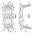
- Figs 8-14 show various views of the fastener assembly of Figs 1-7 (wherein the fastener assembly is shown with bone screws inserted therein and with the toggle plates in a closed, or locked position). More particularly, Fig 8 is a top view, Fig 9 is a side view, Fig 10 is a cross-sectional view taken along line B-B of Fig 8 . Fig 11 is a cross-sectional view taken along line E-E of Fig 8 , Fig 12 is a cross-sectioral view taken along line G-G of Fig 8 , Fig 13 shows detail portion F of Fig 11 , and Fig 14 shows detail portion H of Fig 12 .
- Fig 15-18 show details of two different types of bone screws, not-claimed, which may be utilized with the present invention.
- Figs 19-30 show a number of instruments, not-claimed, which may be utilized in connection with the present invention
- implant assembly 100 may be adapted to be fixed to a spine (not shown) using bone screws 102A-102D (see Figs. 8-14 ).
- each bone screw may have a shank with a thread and a head with a feature for engagement with a driving mechanism, such as a screwdriver.
- a driving mechanism such as a screwdriver.
- 4 bone screws are shown here, any desired number may be used.
- plate member 104 may have apertures 106A-106F extending therethrough (wherein each aperture includes a first region sized to permit the shank of a respective bone screw but not the head of the respective bone screw to pass, and wherein each aperture includes a second region sized to permit both the shank of the respective bone screw and the head of the respective bone screw to pass).
- implant assembly 100 may include toggle plates 108A-108C, wherein each toggle plate 108A-108C may be slidably attached to plate member 104 and wherein each toggle plate 108A-108C may be operatively associated with two of the bone screws (since only four bone screws are shown in this example, only toggle plates 108A and 108C are associated with bone screws in these drawings).
- each toggle plate108A-108C may be slideable to a first position (see Figs. 1-7 ) in which each bone screw associated therewith may be inserted in a respective aperture such that the shank of each of the bone screws passes into the first region and the head of each of the bone screws remains in the second region.
- each toggle plate 108A-108C may be slideable to a second position (see Figs. 8-14 ) in which the head of each bone screw associated therewith may be at least partially covered by the toggle plate.
- each toggle plate 108A-108C between the first position and the second position may, for example, be laterally along the length of plate member 104.
- each toggle plate 108A-108C may be pivotally mounted to plate member 104 (see pivot line "P" of Fig. 13 ) such that at least at the second slidable position each toggle plate108A-108C can pivot relative to the plate member 104 (i.e., each toggle plate108A-108C is thus provided with at least two degrees of freedom of movement relative to plate member 104). It is in this last regard, in particular, that this embodiment of the present invention provides a mechanism via which pressure may be applied to bone screws which are disposed at varying depths relative to the plate member.
- each bone screw 102A-102D may be blocked from backing-out of the plate member 104 (and the underlying bone) while one of the toggle plates associated therewith (i.e., associated with a given bone screw) is in the second slidable position.
- each bone screw 102A-102D may be removed from the plate member 104 (and the underlying bone) while one of the toggle plates associated therewith (i.e., associated with a given bone screw) is in the first slidable position.
- visualization of lock position is provided
- this embodiment may comprise toggle plate locking screws 110A-110C (wherein each toggle plate locking screw 110A-110C may be adapted to pass through each toggle plate 108A-108C) into a respective threaded hole in plate member 104.
- each toggle plate locking screw 110A-110C may be adapted to press down on a respective one of the toggle plates 108A-108C to pivot the toggle plate downward (and onto a respective bone screw) when the toggle plate is in the second slidable position and the associated toggle plate locking screw is rotated in a first direction.
- unlocking e.g., for bone screw removal
- plate member 104 may have a top surface 104A and a bottom surface 104B, wherein the first region of the aperture is adjacent bottom surface 104B of plate member 104, and wherein the second region of the aperture is adjacent top surface 104A of the plate member 104.
- each bone screw 102A-102D may be inserted from top surface 104A of plate member 104 towards bottom surface 104B of plate member 104.
- bottom surface 104B of plate member 104 may be contoured to substantially match a contour of the bone to which the implant assembly 100 is affixed.
- bottom surface 104B of plate member 104 may be curved along at least one axis. In another example (which example is intended to be illustrative and not restrictive), bottom surface 104B of plate member 104 may be curved along a first axis and a second axis. In another example (which example is intended to be illustrative and not restrictive), the first axis and the second axis may be substantially orthogonal to one another.
- the implant assembly may be used for fusing at least two vertebral bodies.
- the implant assembly may be used in an anterior cervical plating procedure.
- the implant assembly may include between four and ten apertures for receiving therein between four and ten bone screws.
- two of the bone screws may be screwed into each of the vertebral bodies through two of the apertures.
- each bone screw may include a threaded shank and the thicker region of each bone screw may include a head.
- the present invention may be constructed to be anatomically friendly and to have any desired minimum and maximum dimensions (e.g., made very narrow to safely accommodate narrow vertebral bodies).
- the present invention may provide ease of use due to one or more of the following features: (a) integral toggle plate mechanism; (b) one step locking and unlocking; (c) self-drilling bone crews (e.g., allow a surgeon to punch or drill and place bone screws); (d) streamlined instrument tray.
- the present invention may provide ease of use by utilizing constrained bone screws and/or unconstrained bone screws (which allow variable angle screw placement).
- the profile and screw placement associated with the plate member may be as follows:
- the plate member may have a length selected from the following configurations:
- the bone screw characteristics may be selected from the following configurations:
- Fig. 15 shows a top view of the head of a fixed or constrained bone screw (that is, a bone screw whose angular position can not be changed while locked within the locking plate);
- Fig. 16 shows a side view of the head and part of the shank of the fixed bone screw of Fig. 15;
- Fig. 17 shows a top view of the head of a variable or unconstrained bone screw (that is, a bone screw whose angular position can be changed while locked within the locking plate);
- Fig. 18 shows a side view of the head and part of the shank of the variable bone screw of Fig. 17 .
- Fig. 19 depicts freehand drill guide 1900 (which may limit drilling depth and restrict angulation when preparing bone to receive a bone screw).
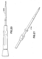
- Fig. 20 depicts drill 2000 (which may utilize a modular handle or power) and which may be provided, for example, in 10mm to 18mm sizes (fixed depth with positive stop).
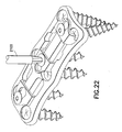
- Fig. 21 depicts tri-lobe screw driver 2100, which may be used to tighten and loosen the toggle plate locking screws (see detail of Fig. 22 ) and which may utilize a toque handle for limiting torque.
- Fig. 23 depicts tap 2300, which may be, for example, 10mm length with positive stop, which may be single use, and which may be used with a modular handle.
- Fig. 24 depicts screw driver 2400, which may be, for example, of one length (with a stop to indicate screw depth), which may have a spring-loaded tip for screw security, and which may be used with a modular handle.
- Fig. 25 depicts tack holder 2500, which may allow easy insertion and removal of temporary tacks (see detail of Fig. 26 ) and which may permit rotation of a beveled knob on the instrument handle to secure or release the tack therefrom.
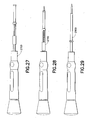
- Fig. 27 depicts a first bone awl 2700, which may provide, for example, 11mm penetration, which may have a spring retracted sleeve (see sleeve in retracted position in Fig. 28 ), and which may be used with a modular handle.
- Fig. 29 depicts a second bone awl 2900, which may provide, for example, 5mm penetration with drill guide (tip length: 5mm) and which may be used with a drill guide and a modular handle.
- Fig. 30 depicts plate bender 3000, which may be used to contour the plate member.
- any desired number of bone screws may be used to fix the device to any desired number of vertebral bodies (and the present invention may be placed at any desired level(s) of the spine). Further, the present invention may be used in conjunction with a spinal rod implantation. Further still, any element described herein may be provided in any desired size (e.g., any element described herein may be provided in any desired custom size or any element described herein may be provided in any desired size selected from a "family" of sizes, such as small, medium, large).
- one or more of the components of the implant assembly may be made from any of the following materials: (a) any biocompatible material (which biocompatible material may be treated to permit bone ingrowth or prohibit bone ingrowth - depending upon the desire of the surgeon); (b) a plastic; (c) a fiber; (d) a polymer; (e) a metal (a pure metal such as titanium and/or an alloy such as Ti-Al-Nb, Ti-6A1-4V, stainless steel); (f) any combination thereof.
- the toggle plates may be slid between positions by pushing, such as with a finger, or by application of a tool or other device. Further still, any steps described herein may be carried out in any desired order (and any desired steps may be added and/or eliminated).
Landscapes
- Health & Medical Sciences (AREA)
- Orthopedic Medicine & Surgery (AREA)
- Surgery (AREA)
- Life Sciences & Earth Sciences (AREA)
- Animal Behavior & Ethology (AREA)
- Veterinary Medicine (AREA)
- Nuclear Medicine, Radiotherapy & Molecular Imaging (AREA)
- Engineering & Computer Science (AREA)
- Biomedical Technology (AREA)
- Heart & Thoracic Surgery (AREA)
- Medical Informatics (AREA)
- Molecular Biology (AREA)
- Public Health (AREA)
- General Health & Medical Sciences (AREA)
- Neurology (AREA)
- Dentistry (AREA)
- Oral & Maxillofacial Surgery (AREA)
- Surgical Instruments (AREA)
- Prostheses (AREA)
- Orthopedics, Nursing, And Contraception (AREA)
- Coating With Molten Metal (AREA)
- Electroplating Methods And Accessories (AREA)
- Absorbent Articles And Supports Therefor (AREA)
- Finger-Pressure Massage (AREA)
- Professional, Industrial, Or Sporting Protective Garments (AREA)
Applications Claiming Priority (1)
| Application Number | Priority Date | Filing Date | Title |
|---|---|---|---|
| US11/228,117 US7662154B2 (en) | 2005-09-16 | 2005-09-16 | Anterior cervical plating system |
Publications (3)
| Publication Number | Publication Date |
|---|---|
| EP1764049A2 EP1764049A2 (en) | 2007-03-21 |
| EP1764049A3 EP1764049A3 (en) | 2008-04-16 |
| EP1764049B1 true EP1764049B1 (en) | 2009-10-28 |
Family
ID=37460927
Family Applications (1)
| Application Number | Title | Priority Date | Filing Date |
|---|---|---|---|
| EP06120789A Not-in-force EP1764049B1 (en) | 2005-09-16 | 2006-09-15 | Anterior Cervical Plating System |
Country Status (11)
| Country | Link |
|---|---|
| US (1) | US7662154B2 (enExample) |
| EP (1) | EP1764049B1 (enExample) |
| JP (1) | JP4976088B2 (enExample) |
| CN (1) | CN1954784A (enExample) |
| AT (1) | ATE446717T1 (enExample) |
| AU (1) | AU2006213976B2 (enExample) |
| BR (1) | BRPI0603817A (enExample) |
| CA (1) | CA2559696A1 (enExample) |
| DE (1) | DE602006010000D1 (enExample) |
| ES (1) | ES2335802T3 (enExample) |
| MX (1) | MXPA06010500A (enExample) |
Families Citing this family (52)
| Publication number | Priority date | Publication date | Assignee | Title |
|---|---|---|---|---|
| US20060129151A1 (en) * | 2002-08-28 | 2006-06-15 | Allen C W | Systems and methods for securing fractures using plates and cable clamps |
| US9078706B2 (en) | 2003-09-30 | 2015-07-14 | X-Spine Systems, Inc. | Intervertebral fusion device utilizing multiple mobile uniaxial and bidirectional screw interface plates |
| US8821553B2 (en) | 2003-09-30 | 2014-09-02 | X-Spine Systems, Inc. | Spinal fusion system utilizing an implant plate having at least one integral lock |
| US8372152B2 (en) * | 2003-09-30 | 2013-02-12 | X-Spine Systems, Inc. | Spinal fusion system utilizing an implant plate having at least one integral lock and ratchet lock |
| US7641701B2 (en) | 2003-09-30 | 2010-01-05 | X-Spine Systems, Inc. | Spinal fusion system and method for fusing spinal bones |
| WO2006116606A2 (en) * | 2005-04-27 | 2006-11-02 | James Marino | Mono-planar pedilcle screw method, system, and kit |
| US8556944B2 (en) * | 2007-07-31 | 2013-10-15 | Stryker Spine | System and method for vertebral body plating |
| WO2009061517A1 (en) * | 2007-11-09 | 2009-05-14 | Stryker Spine | Cervical plate with a feedback device for selective association with bone screw blocking mechanism |
| US20090275990A1 (en) * | 2008-05-05 | 2009-11-05 | Rhausler, Inc. | Anterior cervical plate with locking mechanism |
| US8287574B2 (en) * | 2008-08-06 | 2012-10-16 | The University Of Toledo | Cervical plate assembly |
| US8795340B2 (en) * | 2008-11-07 | 2014-08-05 | Globus Medical, Inc. | Vertical inline plate |
| FR2948553B1 (fr) * | 2009-07-30 | 2012-06-08 | Clariance | Dispositif anti recul a tiroirs pour prothese |
| CN102038545B (zh) * | 2009-10-16 | 2015-04-15 | 上海微创骨科医疗科技有限公司 | 一种颈椎前路钢板的锁紧装置 |
| US8409259B1 (en) | 2010-01-06 | 2013-04-02 | Bernard M. Bedor | Cervical plate system and method |
| US8403970B1 (en) * | 2010-01-06 | 2013-03-26 | Bernard M. Bedor | Cervical plate system and method |
| US8940030B1 (en) | 2011-01-28 | 2015-01-27 | Nuvasive, Inc. | Spinal fixation system and related methods |
| US8668723B2 (en) | 2011-07-19 | 2014-03-11 | Neurostructures, Inc. | Anterior cervical plate |
| US8591556B2 (en) * | 2011-07-19 | 2013-11-26 | Globus Medical, Inc. | Locking confirmation mechanism for a bone screw and plate assembly |
| CN102293681A (zh) * | 2011-08-25 | 2011-12-28 | 尚鹏 | 回转止退型颈椎前路内固定装置 |
| US9265531B2 (en) * | 2012-06-05 | 2016-02-23 | Blackstone Medical, Inc. | Orthopedic devices with a locking mechanism |
| KR101415241B1 (ko) | 2012-10-24 | 2014-07-07 | 주식회사 지에스메디칼 | 경추 고정 장치 |
| US9642652B2 (en) * | 2013-02-13 | 2017-05-09 | Choice Spine, Lp | Variable angle bone plate with semi-constrained articulating screw |
| KR101599603B1 (ko) | 2013-08-26 | 2016-03-03 | 경북대학교 산학협력단 | 의료용 삽입 장치 |
| US9468479B2 (en) | 2013-09-06 | 2016-10-18 | Cardinal Health 247, Inc. | Bone plate |
| US9629664B2 (en) | 2014-01-20 | 2017-04-25 | Neurostructures, Inc. | Anterior cervical plate |
| US9486250B2 (en) | 2014-02-20 | 2016-11-08 | Mastros Innovations, LLC. | Lateral plate |
| KR101639887B1 (ko) | 2014-11-11 | 2016-07-14 | 경북대학교 산학협력단 | 경추 고정 시스템 및 경추 고정용 기구에 사용되는 드라이버 |
| KR101608949B1 (ko) * | 2014-11-19 | 2016-04-04 | 경북대학교 산학협력단 | 경추 고정 시스템, 경추 고정용 기구 및 경추 고정용 기구에 사용되는 드라이버 |
| WO2016137983A1 (en) | 2015-02-24 | 2016-09-01 | X-Spine Systems, Inc. | Modular interspinous fixation system with threaded component |
| KR101670768B1 (ko) | 2015-07-16 | 2016-10-31 | 경북대학교 산학협력단 | 나사못 앵커 조립체 |
| US10874445B2 (en) | 2015-10-13 | 2020-12-29 | Kyungpook National University Industry-Academic Cooperation Foundation | Screw fixing apparatus |
| US10695107B2 (en) * | 2015-12-03 | 2020-06-30 | Warsaw Orthopedic, Inc. | Spinal implant system and methods of use |
| US10206725B2 (en) | 2015-12-06 | 2019-02-19 | Gramercy Extremity Orthopedics Llc | Orthopedic variable screw fixation mechanism |
| KR101712610B1 (ko) | 2015-12-29 | 2017-03-06 | 경북대학교 산학협력단 | 로드 커넥터 |
| US10786368B2 (en) | 2015-12-30 | 2020-09-29 | Nuvasive, Inc. | Interfixated vertebral body replacement and insertion methods |
| KR101791004B1 (ko) | 2016-06-08 | 2017-10-27 | 경북대학교 산학협력단 | 나사못 앵커 조립체 및 나사못 앵커 조립체를 척추 나사못 고정술에 사용하는 방법 |
| US9918750B2 (en) * | 2016-08-04 | 2018-03-20 | Osseus Fusion Systems, Llc | Method, system, and apparatus for temporary anterior cervical plate fixation |
| US10980641B2 (en) | 2017-05-04 | 2021-04-20 | Neurostructures, Inc. | Interbody spacer |
| US10512547B2 (en) | 2017-05-04 | 2019-12-24 | Neurostructures, Inc. | Interbody spacer |
| US11229460B2 (en) | 2017-11-16 | 2022-01-25 | Globus Medical, Inc. | Anterior cervical plate assembly |
| US11234742B2 (en) | 2017-11-16 | 2022-02-01 | Globus Medical, Inc. | Anterior cervical plate assembly |
| US11272963B2 (en) | 2017-11-16 | 2022-03-15 | Globus Medical, Inc. | Anterior cervical plate assembly |
| US11304734B2 (en) | 2017-11-16 | 2022-04-19 | Globus Medical Inc. | Anterior cervical plate assembly |
| US11076892B2 (en) | 2018-08-03 | 2021-08-03 | Neurostructures, Inc. | Anterior cervical plate |
| US11071629B2 (en) | 2018-10-13 | 2021-07-27 | Neurostructures Inc. | Interbody spacer |
| US11793558B2 (en) | 2019-08-30 | 2023-10-24 | K2M, Inc. | All in one plate holder and spring loaded awl |
| US11510708B2 (en) | 2020-02-05 | 2022-11-29 | Adam Isaac Lewis | Thoracolumbar plate with cam lock |
| US11382761B2 (en) | 2020-04-11 | 2022-07-12 | Neurostructures, Inc. | Expandable interbody spacer |
| US11304817B2 (en) | 2020-06-05 | 2022-04-19 | Neurostructures, Inc. | Expandable interbody spacer |
| US11707307B2 (en) | 2020-12-04 | 2023-07-25 | Globus Medical, Inc. | Systems and methods for treating rib fractures and osteotomies using implantation |
| US12102364B2 (en) | 2020-12-04 | 2024-10-01 | Globus Medical, Inc. | Systems and methods for treating rib fractures and osteotomies using implantation |
| US11717419B2 (en) | 2020-12-10 | 2023-08-08 | Neurostructures, Inc. | Expandable interbody spacer |
Family Cites Families (13)
| Publication number | Priority date | Publication date | Assignee | Title |
|---|---|---|---|---|
| US5428542A (en) * | 1991-07-05 | 1995-06-27 | Liesveld; Aura L. | Vehicle mileage and information recording method and system |
| ATE395001T1 (de) * | 1997-02-11 | 2008-05-15 | Warsaw Orthopedic Inc | Platte für die vordere halswirbelsäule mit fixierungssystem für eine schraube |
| CA2279938C (en) * | 1997-02-11 | 2006-01-31 | Gary Karlin Michelson | Skeletal plating system |
| ZA983955B (en) * | 1997-05-15 | 2001-08-13 | Sdgi Holdings Inc | Anterior cervical plating system. |
| US20040220571A1 (en) * | 1998-04-30 | 2004-11-04 | Richard Assaker | Bone plate assembly |
| US6533786B1 (en) * | 1999-10-13 | 2003-03-18 | Sdgi Holdings, Inc. | Anterior cervical plating system |
| FR2778088B1 (fr) * | 1998-04-30 | 2000-09-08 | Materiel Orthopedique En Abreg | Implant anterieur notamment pour le rachis cervical |
| US6224602B1 (en) * | 1999-10-11 | 2001-05-01 | Interpore Cross International | Bone stabilization plate with a secured-locking mechanism for cervical fixation |
| US6602256B1 (en) * | 1999-10-11 | 2003-08-05 | Cross Medical Products, Inc. | Bone stabilization plate with a secured-locking mechanism for cervical fixation |
| US6692503B2 (en) * | 1999-10-13 | 2004-02-17 | Sdgi Holdings, Inc | System and method for securing a plate to the spinal column |
| US6503250B2 (en) * | 2000-11-28 | 2003-01-07 | Kamaljit S. Paul | Bone support assembly |
| US6945973B2 (en) * | 2003-05-01 | 2005-09-20 | Nuvasive, Inc. | Slidable bone plate system |
| US7306605B2 (en) * | 2003-10-02 | 2007-12-11 | Zimmer Spine, Inc. | Anterior cervical plate |
-
2005
- 2005-09-16 US US11/228,117 patent/US7662154B2/en active Active
-
2006
- 2006-09-14 MX MXPA06010500A patent/MXPA06010500A/es not_active Application Discontinuation
- 2006-09-14 AU AU2006213976A patent/AU2006213976B2/en not_active Ceased
- 2006-09-14 CA CA002559696A patent/CA2559696A1/en not_active Abandoned
- 2006-09-15 AT AT06120789T patent/ATE446717T1/de not_active IP Right Cessation
- 2006-09-15 ES ES06120789T patent/ES2335802T3/es active Active
- 2006-09-15 CN CNA2006101486864A patent/CN1954784A/zh active Pending
- 2006-09-15 DE DE602006010000T patent/DE602006010000D1/de active Active
- 2006-09-15 EP EP06120789A patent/EP1764049B1/en not_active Not-in-force
- 2006-09-15 JP JP2006251104A patent/JP4976088B2/ja not_active Expired - Fee Related
- 2006-09-18 BR BRPI0603817-4A patent/BRPI0603817A/pt not_active Application Discontinuation
Also Published As
| Publication number | Publication date |
|---|---|
| DE602006010000D1 (de) | 2009-12-10 |
| EP1764049A3 (en) | 2008-04-16 |
| CA2559696A1 (en) | 2007-03-16 |
| CN1954784A (zh) | 2007-05-02 |
| EP1764049A2 (en) | 2007-03-21 |
| AU2006213976A1 (en) | 2007-04-05 |
| ES2335802T3 (es) | 2010-04-05 |
| US20070083203A1 (en) | 2007-04-12 |
| BRPI0603817A (pt) | 2007-08-14 |
| AU2006213976B2 (en) | 2012-08-23 |
| ATE446717T1 (de) | 2009-11-15 |
| US7662154B2 (en) | 2010-02-16 |
| MXPA06010500A (es) | 2007-06-11 |
| JP4976088B2 (ja) | 2012-07-18 |
| JP2007083039A (ja) | 2007-04-05 |
Similar Documents
| Publication | Publication Date | Title |
|---|---|---|
| EP1764049B1 (en) | Anterior Cervical Plating System | |
| CA2535382C (en) | Quick-release drill guide assembly for bone plate | |
| JP5662442B2 (ja) | 骨プレートのネジブロックシステム及び方法 | |
| US7731721B2 (en) | Plating system with multiple function drill guide | |
| US6379364B1 (en) | Dual drill guide for a locking bone plate | |
| EP1534142B1 (en) | System for stabilizing a portion of the spine | |
| EP1276425B1 (en) | Remotely aligned surgical drill guide | |
| US7566302B2 (en) | Expandable access device | |
| EP2405833B1 (en) | Spinal fixation element rotation instrument | |
| US10245015B2 (en) | Retractor with modular tap assemblies | |
| AU2008282932B2 (en) | System and method for vertebral body plating | |
| US8911476B2 (en) | Bone plates, screws, and instruments | |
| EP2196160B1 (en) | Adjustable pin drill guide | |
| CA2562367A1 (en) | Free hand drill guide | |
| HK1102218A (en) | Anterior cervical plating system | |
| ZA200206095B (en) | Remotely aligned surgical drill guide. |
Legal Events
| Date | Code | Title | Description |
|---|---|---|---|
| PUAI | Public reference made under article 153(3) epc to a published international application that has entered the european phase |
Free format text: ORIGINAL CODE: 0009012 |
|
| AK | Designated contracting states |
Kind code of ref document: A2 Designated state(s): AT BE BG CH CY CZ DE DK EE ES FI FR GB GR HU IE IS IT LI LT LU LV MC NL PL PT RO SE SI SK TR |
|
| AX | Request for extension of the european patent |
Extension state: AL BA HR MK YU |
|
| REG | Reference to a national code |
Ref country code: HK Ref legal event code: DE Ref document number: 1102218 Country of ref document: HK |
|
| PUAL | Search report despatched |
Free format text: ORIGINAL CODE: 0009013 |
|
| AK | Designated contracting states |
Kind code of ref document: A3 Designated state(s): AT BE BG CH CY CZ DE DK EE ES FI FR GB GR HU IE IS IT LI LT LU LV MC NL PL PT RO SE SI SK TR |
|
| AX | Request for extension of the european patent |
Extension state: AL BA HR MK RS |
|
| 17P | Request for examination filed |
Effective date: 20081015 |
|
| 17Q | First examination report despatched |
Effective date: 20081120 |
|
| AKX | Designation fees paid |
Designated state(s): AT BE BG CH CY CZ DE DK EE ES FI FR GB GR HU IE IS IT LI LT LU LV MC NL PL PT RO SE SI SK TR |
|
| GRAP | Despatch of communication of intention to grant a patent |
Free format text: ORIGINAL CODE: EPIDOSNIGR1 |
|
| GRAS | Grant fee paid |
Free format text: ORIGINAL CODE: EPIDOSNIGR3 |
|
| GRAA | (expected) grant |
Free format text: ORIGINAL CODE: 0009210 |
|
| AK | Designated contracting states |
Kind code of ref document: B1 Designated state(s): AT BE BG CH CY CZ DE DK EE ES FI FR GB GR HU IE IS IT LI LT LU LV MC NL PL PT RO SE SI SK TR |
|
| REG | Reference to a national code |
Ref country code: GB Ref legal event code: FG4D |
|
| REG | Reference to a national code |
Ref country code: CH Ref legal event code: EP |
|
| REG | Reference to a national code |
Ref country code: IE Ref legal event code: FG4D |
|
| REF | Corresponds to: |
Ref document number: 602006010000 Country of ref document: DE Date of ref document: 20091210 Kind code of ref document: P |
|
| LTIE | Lt: invalidation of european patent or patent extension |
Effective date: 20091028 |
|
| NLV1 | Nl: lapsed or annulled due to failure to fulfill the requirements of art. 29p and 29m of the patents act | ||
| REG | Reference to a national code |
Ref country code: ES Ref legal event code: FG2A Ref document number: 2335802 Country of ref document: ES Kind code of ref document: T3 |
|
| PG25 | Lapsed in a contracting state [announced via postgrant information from national office to epo] |
Ref country code: PT Free format text: LAPSE BECAUSE OF FAILURE TO SUBMIT A TRANSLATION OF THE DESCRIPTION OR TO PAY THE FEE WITHIN THE PRESCRIBED TIME-LIMIT Effective date: 20100301 Ref country code: SE Free format text: LAPSE BECAUSE OF FAILURE TO SUBMIT A TRANSLATION OF THE DESCRIPTION OR TO PAY THE FEE WITHIN THE PRESCRIBED TIME-LIMIT Effective date: 20091028 Ref country code: FI Free format text: LAPSE BECAUSE OF FAILURE TO SUBMIT A TRANSLATION OF THE DESCRIPTION OR TO PAY THE FEE WITHIN THE PRESCRIBED TIME-LIMIT Effective date: 20091028 Ref country code: LT Free format text: LAPSE BECAUSE OF FAILURE TO SUBMIT A TRANSLATION OF THE DESCRIPTION OR TO PAY THE FEE WITHIN THE PRESCRIBED TIME-LIMIT Effective date: 20091028 Ref country code: IS Free format text: LAPSE BECAUSE OF FAILURE TO SUBMIT A TRANSLATION OF THE DESCRIPTION OR TO PAY THE FEE WITHIN THE PRESCRIBED TIME-LIMIT Effective date: 20100228 |
|
| PG25 | Lapsed in a contracting state [announced via postgrant information from national office to epo] |
Ref country code: SI Free format text: LAPSE BECAUSE OF FAILURE TO SUBMIT A TRANSLATION OF THE DESCRIPTION OR TO PAY THE FEE WITHIN THE PRESCRIBED TIME-LIMIT Effective date: 20091028 Ref country code: CY Free format text: LAPSE BECAUSE OF FAILURE TO SUBMIT A TRANSLATION OF THE DESCRIPTION OR TO PAY THE FEE WITHIN THE PRESCRIBED TIME-LIMIT Effective date: 20091028 Ref country code: PL Free format text: LAPSE BECAUSE OF FAILURE TO SUBMIT A TRANSLATION OF THE DESCRIPTION OR TO PAY THE FEE WITHIN THE PRESCRIBED TIME-LIMIT Effective date: 20091028 Ref country code: LV Free format text: LAPSE BECAUSE OF FAILURE TO SUBMIT A TRANSLATION OF THE DESCRIPTION OR TO PAY THE FEE WITHIN THE PRESCRIBED TIME-LIMIT Effective date: 20091028 |
|
| PG25 | Lapsed in a contracting state [announced via postgrant information from national office to epo] |
Ref country code: BE Free format text: LAPSE BECAUSE OF FAILURE TO SUBMIT A TRANSLATION OF THE DESCRIPTION OR TO PAY THE FEE WITHIN THE PRESCRIBED TIME-LIMIT Effective date: 20091028 Ref country code: AT Free format text: LAPSE BECAUSE OF FAILURE TO SUBMIT A TRANSLATION OF THE DESCRIPTION OR TO PAY THE FEE WITHIN THE PRESCRIBED TIME-LIMIT Effective date: 20091028 |
|
| PG25 | Lapsed in a contracting state [announced via postgrant information from national office to epo] |
Ref country code: BG Free format text: LAPSE BECAUSE OF FAILURE TO SUBMIT A TRANSLATION OF THE DESCRIPTION OR TO PAY THE FEE WITHIN THE PRESCRIBED TIME-LIMIT Effective date: 20100128 Ref country code: EE Free format text: LAPSE BECAUSE OF FAILURE TO SUBMIT A TRANSLATION OF THE DESCRIPTION OR TO PAY THE FEE WITHIN THE PRESCRIBED TIME-LIMIT Effective date: 20091028 Ref country code: RO Free format text: LAPSE BECAUSE OF FAILURE TO SUBMIT A TRANSLATION OF THE DESCRIPTION OR TO PAY THE FEE WITHIN THE PRESCRIBED TIME-LIMIT Effective date: 20091028 Ref country code: DK Free format text: LAPSE BECAUSE OF FAILURE TO SUBMIT A TRANSLATION OF THE DESCRIPTION OR TO PAY THE FEE WITHIN THE PRESCRIBED TIME-LIMIT Effective date: 20091028 |
|
| PG25 | Lapsed in a contracting state [announced via postgrant information from national office to epo] |
Ref country code: SK Free format text: LAPSE BECAUSE OF FAILURE TO SUBMIT A TRANSLATION OF THE DESCRIPTION OR TO PAY THE FEE WITHIN THE PRESCRIBED TIME-LIMIT Effective date: 20091028 Ref country code: CZ Free format text: LAPSE BECAUSE OF FAILURE TO SUBMIT A TRANSLATION OF THE DESCRIPTION OR TO PAY THE FEE WITHIN THE PRESCRIBED TIME-LIMIT Effective date: 20091028 |
|
| PLBE | No opposition filed within time limit |
Free format text: ORIGINAL CODE: 0009261 |
|
| STAA | Information on the status of an ep patent application or granted ep patent |
Free format text: STATUS: NO OPPOSITION FILED WITHIN TIME LIMIT |
|
| 26N | No opposition filed |
Effective date: 20100729 |
|
| PG25 | Lapsed in a contracting state [announced via postgrant information from national office to epo] |
Ref country code: GR Free format text: LAPSE BECAUSE OF FAILURE TO SUBMIT A TRANSLATION OF THE DESCRIPTION OR TO PAY THE FEE WITHIN THE PRESCRIBED TIME-LIMIT Effective date: 20100129 |
|
| PG25 | Lapsed in a contracting state [announced via postgrant information from national office to epo] |
Ref country code: MC Free format text: LAPSE BECAUSE OF NON-PAYMENT OF DUE FEES Effective date: 20100930 |
|
| REG | Reference to a national code |
Ref country code: CH Ref legal event code: PL |
|
| PG25 | Lapsed in a contracting state [announced via postgrant information from national office to epo] |
Ref country code: IE Free format text: LAPSE BECAUSE OF NON-PAYMENT OF DUE FEES Effective date: 20100915 Ref country code: LI Free format text: LAPSE BECAUSE OF NON-PAYMENT OF DUE FEES Effective date: 20100930 Ref country code: CH Free format text: LAPSE BECAUSE OF NON-PAYMENT OF DUE FEES Effective date: 20100930 |
|
| PG25 | Lapsed in a contracting state [announced via postgrant information from national office to epo] |
Ref country code: NL Free format text: LAPSE BECAUSE OF FAILURE TO SUBMIT A TRANSLATION OF THE DESCRIPTION OR TO PAY THE FEE WITHIN THE PRESCRIBED TIME-LIMIT Effective date: 20091028 Ref country code: LU Free format text: LAPSE BECAUSE OF NON-PAYMENT OF DUE FEES Effective date: 20100915 Ref country code: HU Free format text: LAPSE BECAUSE OF FAILURE TO SUBMIT A TRANSLATION OF THE DESCRIPTION OR TO PAY THE FEE WITHIN THE PRESCRIBED TIME-LIMIT Effective date: 20100429 |
|
| PG25 | Lapsed in a contracting state [announced via postgrant information from national office to epo] |
Ref country code: TR Free format text: LAPSE BECAUSE OF FAILURE TO SUBMIT A TRANSLATION OF THE DESCRIPTION OR TO PAY THE FEE WITHIN THE PRESCRIBED TIME-LIMIT Effective date: 20091028 |
|
| REG | Reference to a national code |
Ref country code: HK Ref legal event code: WD Ref document number: 1102218 Country of ref document: HK |
|
| REG | Reference to a national code |
Ref country code: FR Ref legal event code: PLFP Year of fee payment: 10 |
|
| REG | Reference to a national code |
Ref country code: GB Ref legal event code: 732E Free format text: REGISTERED BETWEEN 20151029 AND 20151104 |
|
| REG | Reference to a national code |
Ref country code: FR Ref legal event code: PLFP Year of fee payment: 11 |
|
| REG | Reference to a national code |
Ref country code: FR Ref legal event code: PLFP Year of fee payment: 12 |
|
| PGFP | Annual fee paid to national office [announced via postgrant information from national office to epo] |
Ref country code: FR Payment date: 20170823 Year of fee payment: 12 Ref country code: GB Payment date: 20170829 Year of fee payment: 12 Ref country code: IT Payment date: 20170913 Year of fee payment: 12 |
|
| PGFP | Annual fee paid to national office [announced via postgrant information from national office to epo] |
Ref country code: DE Payment date: 20170928 Year of fee payment: 12 |
|
| PGFP | Annual fee paid to national office [announced via postgrant information from national office to epo] |
Ref country code: ES Payment date: 20171004 Year of fee payment: 12 |
|
| REG | Reference to a national code |
Ref country code: DE Ref legal event code: R119 Ref document number: 602006010000 Country of ref document: DE |
|
| GBPC | Gb: european patent ceased through non-payment of renewal fee |
Effective date: 20180915 |
|
| PG25 | Lapsed in a contracting state [announced via postgrant information from national office to epo] |
Ref country code: DE Free format text: LAPSE BECAUSE OF NON-PAYMENT OF DUE FEES Effective date: 20190402 Ref country code: IT Free format text: LAPSE BECAUSE OF NON-PAYMENT OF DUE FEES Effective date: 20180915 |
|
| PG25 | Lapsed in a contracting state [announced via postgrant information from national office to epo] |
Ref country code: FR Free format text: LAPSE BECAUSE OF NON-PAYMENT OF DUE FEES Effective date: 20180930 |
|
| PG25 | Lapsed in a contracting state [announced via postgrant information from national office to epo] |
Ref country code: GB Free format text: LAPSE BECAUSE OF NON-PAYMENT OF DUE FEES Effective date: 20180915 |
|
| REG | Reference to a national code |
Ref country code: ES Ref legal event code: FD2A Effective date: 20191031 |
|
| PG25 | Lapsed in a contracting state [announced via postgrant information from national office to epo] |
Ref country code: ES Free format text: LAPSE BECAUSE OF NON-PAYMENT OF DUE FEES Effective date: 20180916 |