EP1764018A2 - System for the mounting of a plate - Google Patents
System for the mounting of a plate Download PDFInfo
- Publication number
- EP1764018A2 EP1764018A2 EP06076410A EP06076410A EP1764018A2 EP 1764018 A2 EP1764018 A2 EP 1764018A2 EP 06076410 A EP06076410 A EP 06076410A EP 06076410 A EP06076410 A EP 06076410A EP 1764018 A2 EP1764018 A2 EP 1764018A2
- Authority
- EP
- European Patent Office
- Prior art keywords
- profile
- plate
- adjustment
- carrier profile
- carrier
- Prior art date
- Legal status (The legal status is an assumption and is not a legal conclusion. Google has not performed a legal analysis and makes no representation as to the accuracy of the status listed.)
- Granted
Links
- 238000007789 sealing Methods 0.000 claims description 5
- 239000011521 glass Substances 0.000 description 6
- 238000005192 partition Methods 0.000 description 4
- 230000002411 adverse Effects 0.000 description 1
- 230000015572 biosynthetic process Effects 0.000 description 1
- 230000003670 easy-to-clean Effects 0.000 description 1
- XLYOFNOQVPJJNP-UHFFFAOYSA-N water Substances O XLYOFNOQVPJJNP-UHFFFAOYSA-N 0.000 description 1
Images

Classifications
-
- A—HUMAN NECESSITIES
- A47—FURNITURE; DOMESTIC ARTICLES OR APPLIANCES; COFFEE MILLS; SPICE MILLS; SUCTION CLEANERS IN GENERAL
- A47K—SANITARY EQUIPMENT NOT OTHERWISE PROVIDED FOR; TOILET ACCESSORIES
- A47K3/00—Baths; Douches; Appurtenances therefor
- A47K3/28—Showers or bathing douches
- A47K3/30—Screens or collapsible cabinets for showers or baths
- A47K2003/307—Adjustable connections to the wall
Definitions
- the invention relates to a system for fastening a plate or a pane, preferably for forming a shower or bathtub partition according to the preamble of claim 1.
- a shower enclosure with a pivotable about the vertical pivot axis door with a glass or plastic door leaf known.
- two-part trained spars are provided, wherein in one of the spar parts a groove extending in the vertical direction is formed, in which the spar facing the edge portion of the wall part or the door insertable and by means of screws in this vertically extending Nut is fixable.
- the other spar part After fixing the wall or the door in the vertical groove in the first spar part, the other spar part is connected or glued to the first spar part, at the same time covering the fixing screws.
- the screws can penetrate the wall part or the door leaf directly or penetrate a pushed onto the end edges of the wall or the door leaf skirt and thus establish a connection.
- a disadvantage of this known design that required after a long period of use readjustments are difficult or difficult.
- a device for fixing a glass sheet to a wall to form a shower or bathtub partition wherein a clamping unit is displaceable relative to a base profile and a clamping element orthogonal to the wall, and the device by means of a on the one hand and on the wall on the other final Blendprofils is covered.
- the disk to be fastened can be fixed between the base profile and the clamping element with the clamping unit projecting through a recess in the disk.
- the glass sheets must therefore be provided in this embodiment with corresponding recesses.
- the invention has for its object to provide a system for fixing a plate, in particular a frameless glass pane on a wall, with an adjustment of the disc is transverse to the wall with a sufficient adjustment possible, with the disc for reducing the production costs none separate processing is required.
- the solution according to the invention has the advantage that even without recesses in the pane, a sufficient adjustment range can be made available without adversely affecting the overall external impression.
- the invention accordingly shows a system for fixing a plate or disc to a wall, comprising a carrier profile to be fastened to the wall, an adjustment profile to be fastened to the plate, and at least one clip and a cover profile.
- the carrier profile is U-shaped and the plate to be fastened is held with the adjustment between a leg of the carrier profile and the inserted between the plate and the other leg of the carrier profile clip and the plate by at least one carrier profile and the bracket through-protruding fastener in Adjustment profile can be fixed within an adjustment range predetermined by the bracket and carrier profile.
- the plate is adjustable in the carrier profile on the adjustment. The adjustment results in this case advantageously by the provided in the bracket and carrier profile slots.
- the clip is an essential feature of the invention.
- the bracket also serves the mounting backup, ie the plate or glass can not fall out of the carrier profile through the clip holder during assembly without final fixation by a fastener. It is advantageously provided that the clip can be guided in the slot-shaped recesses of the carrier profile.
- a leg of the carrier profile to at least two slot-shaped recesses and at least one slot.
- an elongated rail for the carrier profile is preferably used an elongated rail.
- the cover profile is fastened according to a special feature of the invention by a tongue and groove system on the introduced in the carrier profile bracket, i.
- the clip also advantageously serves as a carrier or holder for the cover profile
- the clip engages in an angled mounting structure of the cover, whereby a secure attachment of the cover is achieved.
- the plate is fastened by the adjustment profile with the clip in the carrier profile, preferably screwed.
- the adjustment profile is designed as an applied on a side edge of the plate elongated rail with a hollow rail, wherein at least one opening for receiving the fastening element is provided in the region of the hollow rail.
- a sealing profile is preferably arranged on the hollow rail.
- the clip can be inserted into the slot, preferably can be clamped and has an upstanding tab.
- a clamping receptacle for holding the tab is arranged on the inside of the cover.
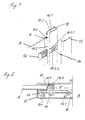
- FIG. 1 shows, in a partial view and in an exploded view, the system-associated elements for forming a shower enclosure and fastening to a wall (not shown).
- the system according to the invention shown in FIGS. 1 and 2 comprises a carrier profile 10 to be fastened to a wall B, an adjusting profile 11 to be fastened to a pane A, a clamp 12 and a cover profile 13.
- the carrier profile 10 is U-shaped.
- the disk A to be fastened is held with the adjustment profile 10 between a leg 10. 1 of the carrier profile 10 and the clamp 12 to be introduced between the plate A and the other leg 10. 2 of the carrier profile 10.
- the bracket 12 sits self-holding in the support section 10 and the disc A can no longer fall out of the support section 10. About the bracket 12 is still a firm connection of carrier profile 10 and
- the clip 12 is guided in the recesses 10.2.1 of the carrier profile 10.
- the disc A is fixed by a the carrier profile 10 and the bracket 12 projecting screw 14 (fastener) in the adjustment 11 in the adjustment "x", with the adjustment "x" from the parenthesis and
- Carrier profile introduced slots 10.2.2 and 12.1 results.
- the disc A is screwed by the adjustment profile 11 with the bracket 12 in the support section 10, without direct mechanical action the disc or recesses to be introduced into the disc for receiving parts required for attachment.
- the carrier profile 10 is formed as an elongated rail, wherein the leg 10.2 of the carrier profile 10 has two slot-shaped recesses 10.2.1 and a slot 10.2.2.
- the clip (12) engages in an angled fastening structure 13.1 of the cover profile 13.
- the covering profile determines the aesthetic overall impression of the system, since it covers the entire area between the pane and the wall.
- the adjustment profile 11 is formed as an applied on a side edge of the disc A elongated rail with a connected hollow rail 11.1.
- an opening 11.2 is provided for receiving the fastening element (14) designed as a screw, which engages in the hollow rail 11.1 when it is fixed.
- a sealing profile 11.3 is arranged on the hollow rail 11.1, which is preferably latched via spring elements in the hollow rail 11.1.
- the sealing profile 11.3 seals the rear part of the carrier profile 10 against a possible between the disc A and the leg 10.1 water inlet.
- the system according to the invention has no protruding parts and is therefore easy to clean. For attachment to the wall only a few components are needed. A readjustment of the system is possible at any time in a simple manner. As shown in Fig. 2, the system allows a sufficient adjustment range "x" for an adjustment of the disc across the wall to compensate for misalignment or different dimensions of shower or tub.
- FIG. 3 shows a partial view of a preferred variant of the system for fastening a pane to form a shower enclosure.
- the difference here is primarily in the formation of the clip 12 and the associated other type of attachment to the cover 13.
- the clip 12 is preferably inserted into the slot 10.2.2 self-locking or clamped.
- the bracket 12 has in this embodiment only an upstanding tab (12.2).
- the receptacle 13.2 can be arranged adjustable between the rails 13.3.
Abstract
Description
Die Erfindung betrifft ein System zur Befestigung einer Platte oder einer Scheibe, vorzugsweise zur Bildung einer Dusch- oder Badewannenabtrennung nach dem Oberbegriff des Anspruchs 1.The invention relates to a system for fastening a plate or a pane, preferably for forming a shower or bathtub partition according to the preamble of claim 1.
Zur Befestigung von Platten oder Scheiben an einer Wand, insbesondere für eine Dusch- oder Badewannenabtrennung, sind verschiedene Vorrichtungen bekannt. Für teilgerahmte Glasscheiben werden dazu meist Profile genutzt, welche in geeigneter Weise an der Wand befestigt werden, wobei die Scheibe in einem Profil oder einer Profileinheit geführt wird. Dabei ist es oft erforderlich die Scheibe in der Profileinheit justierbar anzuordnen, um die Duschabtrennung an Fluchtungsfehler oder an unterschiedliche Maße von Dusche oder Wanne anpassen zu können. Dabei kommt es häufig auf den zur Verfügung stehenden Stellweg und der Genauigkeit der Verstellbarkeit an.For attachment of plates or disks on a wall, in particular for a shower or bathtub partition, various devices are known. For partially framed glass panels, profiles are usually used for this purpose, which are fastened in a suitable manner to the wall, wherein the pane is guided in a profile or a profile unit. It is often necessary to arrange the disc adjustable in the profile unit to adjust the shower enclosure to misalignment or to different dimensions of shower or tub can. It often depends on the available travel and accuracy of adjustability.
Aus der
Aus der
In der
Der Erfindung liegt die Aufgabe zugrunde, ein System zur Befestigung einer Platte, insbesondere einer rahmenlosen Glasscheibe an einer Wand zu schaffen, mit der eine Justierung der Scheibe quer zur Wand mit einem ausreichenden Verstellbereich möglich ist, wobei für die Scheibe dafür zur Reduzierung der Herstellungskosten keiner gesonderte Bearbeitung erforderlich ist.The invention has for its object to provide a system for fixing a plate, in particular a frameless glass pane on a wall, with an adjustment of the disc is transverse to the wall with a sufficient adjustment possible, with the disc for reducing the production costs none separate processing is required.
Erfindungsgemäß wird diese Aufgabe durch die Merkmale des Anspruchs 1 gelöst. Besondere Ausführungen der Erfindung zeigen die Merkmale der zugehörigen Ansprüche.According to the invention, this object is solved by the features of claim 1. Particular embodiments of the invention show the features of the appended claims.
Die erfindungsgemäße Lösung hat den Vorteil, dass auch ohne Ausnehmungen in der Scheibe ein ausreichender Verstellbereich zur Verfügung gestellt werden kann, ohne dabei den äußeren Gesamteindruck zu beeinträchtigen.The solution according to the invention has the advantage that even without recesses in the pane, a sufficient adjustment range can be made available without adversely affecting the overall external impression.
Die Erfindung zeigt demnach ein System zur Befestigung einer Platte oder Scheibe an einer Wand, umfassend ein an der Wand zu befestigendes Trägerprofil, ein an der Platte zu befestigendes Verstellprofil, sowie mindestens eine Klammer und ein Abdeckprofil. wobei das Trägerprofil u-förmig ausgebildet ist und die zu befestigende Platte mit dem Verstellprofil zwischen einem Schenkel des Trägerprofils und der zwischen der Platte und dem anderen Schenkel des Trägerprofils einzuführenden Klammer gehalten wird und die Platte durch mindestens ein das Trägerprofil und die Klammer durchragendes Befestigungselement im Verstellprofil innerhalb eines durch Klammer und Trägerprofil vorgegebenen Verstellbereiches fixierbar ist. Dabei ist die Platte im Trägerprofil über das Verstellprofil justierbar. Der Verstellbereich ergibt sich dabei vorteilhaft durch die in Klammer und Trägerprofil vorgesehenen Langlöcher.The invention accordingly shows a system for fixing a plate or disc to a wall, comprising a carrier profile to be fastened to the wall, an adjustment profile to be fastened to the plate, and at least one clip and a cover profile. wherein the carrier profile is U-shaped and the plate to be fastened is held with the adjustment between a leg of the carrier profile and the inserted between the plate and the other leg of the carrier profile clip and the plate by at least one carrier profile and the bracket through-protruding fastener in Adjustment profile can be fixed within an adjustment range predetermined by the bracket and carrier profile. The plate is adjustable in the carrier profile on the adjustment. The adjustment results in this case advantageously by the provided in the bracket and carrier profile slots.
Durch das erfindungsgemäße System wird ein großzügiger Verstellbereich gewährleistet, wobei in die Scheibe oder Platte einzubringende Ausnehmungen nicht erforderlich sind. Dabei stellt insbesondere die Klammer ein wesentliches Merkmal der Erfindung dar. Die Klammer dient dabei auch der Montagesicherung, d.h. die Platte oder Glasscheibe kann durch die Klammerhalterung während der Montage auch ohne abschließende Fixierung durch ein Befestigungselement nicht mehr aus dem Trägerprofil fallen. Vorteilhaft ist dabei vorgesehen, dass die Klammer in den schlitzförmigen Ausnehmungen des Trägerprofils führbar ist.By the system according to the invention a generous adjustment range is ensured, wherein in the disc or plate to be introduced recesses are not required. In this case, in particular, the clip is an essential feature of the invention. The bracket also serves the mounting backup, ie the plate or glass can not fall out of the carrier profile through the clip holder during assembly without final fixation by a fastener. It is advantageously provided that the clip can be guided in the slot-shaped recesses of the carrier profile.
Vorteilhaft weist ein Schenkel des Trägerprofils dazu mindestens zwei schlitzförmige Ausnehmungen und mindestens ein Langloch auf. Für das Trägerprofil wird dazu vorzugsweise eine langgestreckte Profilschiene eingesetzt. Das Abdeckprofil ist nach einem besonderen Merkmal der Erfindung durch ein Nut- und Federsystem an der im Trägerprofil eingebrachten Klammer befestigbar, d.h. die Klammer dient in vorteilhafter Weise auch als Träger bzw. Halter für das AbdeckprofilAdvantageously, a leg of the carrier profile to at least two slot-shaped recesses and at least one slot. For the carrier profile is preferably used an elongated rail. The cover profile is fastened according to a special feature of the invention by a tongue and groove system on the introduced in the carrier profile bracket, i. The clip also advantageously serves as a carrier or holder for the cover profile
Nach einer vorteilhaften Ausführung greift die Klammer in eine abgewinkelte Befestigungsstruktur des Abdeckprofils ein, wodurch eine sichere Befestigung der Abdeckung erreicht wird. Gleichzeitig ist die Platte durch das Verstellprofil mit der Klammer im Trägerprofil befestigbar, vorzugsweise verschraubbar.According to an advantageous embodiment, the clip engages in an angled mounting structure of the cover, whereby a secure attachment of the cover is achieved. At the same time, the plate is fastened by the adjustment profile with the clip in the carrier profile, preferably screwed.
Vorteilhaft ist das Verstellprofil als eine auf einer Seitenkante der Platte aufgebrachte langgestreckte Profilschiene mit einer Hohlschiene ausgebildet, wobei im Bereich der Hohlschiene mindestens eine Öffnung zur Aufnahme des Befestigungselementes vorgesehen ist. Zur Abdichtung der Scheibe ist an der Hohlschiene vorzugsweise ein Dichtprofil angeordnet. Nach einer weiteren Ausführung der Erfindung ist vorgesehen, dass die Klammer in das Langloch einsetzbar ist, vorzugsweise einklemmbar ist und eine nach oben stehende Lasche aufweist. Bei dieser bevorzugten Variante ist an der Innenseite des Abdeckprofils eine klemmende Aufnahme zur Halterung der Lasche angeordnet.Advantageously, the adjustment profile is designed as an applied on a side edge of the plate elongated rail with a hollow rail, wherein at least one opening for receiving the fastening element is provided in the region of the hollow rail. To seal the disc, a sealing profile is preferably arranged on the hollow rail. According to a further embodiment of the invention it is provided that the clip can be inserted into the slot, preferably can be clamped and has an upstanding tab. In this preferred variant, a clamping receptacle for holding the tab is arranged on the inside of the cover.
Weitere Merkmale und Vorteile der Erfindung ergeben sich aus der nachfolgenden Beschreibung eines bevorzugten, jedoch nicht beschränkenden Ausführungsbeispieles anhand der Figuren.Further features and advantages of the invention will become apparent from the following description of a preferred, but not limiting embodiment with reference to the figures.
Es zeigen
- Fig.1 eine Teilansicht eines Systems zur Befestigung einer Scheibe zur Bildung einer Duschabtrennung in Explosionsdarstellung,
- Fig.2 ein Querschnitt durch das System bei Befestigung an einer Wand,
- Fig.3 eine Teilansicht einer bevorzugten Variante des Systems zur Befestigung einer Scheibe zur Bildung einer Duschabtrennung.
- 1 shows a partial view of a system for fastening a pane to form a shower enclosure in an exploded view,
- 2 shows a cross section through the system when attached to a wall,
- 3 shows a partial view of a preferred variant of the system for fixing a pane to form a shower enclosure.
In der Fig.1 werden in einer Teilansicht und in Explosionsdarstellung die zum System gehörenden Elemente zur Bildung einer Duschabtrennung und Befestigung an einer Wand (nicht dargestellt) gezeigt.FIG. 1 shows, in a partial view and in an exploded view, the system-associated elements for forming a shower enclosure and fastening to a wall (not shown).
Das in den Figuren 1 und 2 gezeigte erfindungsgemäße System umfasst ein an einer Wand B zu befestigendes Trägerprofil 10, ein an einer Scheibe A zu befestigendes Verstellprofil 11, eine Klammer 12 und ein Abdeckprofil 13. Das Trägerprofil 10 ist u-förmig ausgebildet. Die zu befestigende Scheibe A wird mit dem Verstellprofil 10 zwischen einem Schenkel 10.1 des Trägerprofils 10 und der zwischen der Platte A und dem anderen Schenkel 10.2 des Trägerprofils 10 einzuführenden Klammer 12 gehalten. Die Klammer 12 sitzt dabei selbsthaltend im Trägerprofil 10 und die Scheibe A kann nicht mehr aus dem Trägerprofil 10 fallen. Über die Klammer 12 wird weiter eine feste Verbindung von Trägerprofil 10 undThe system according to the invention shown in FIGS. 1 and 2 comprises a
Verstellprofil 11 geschaffen. Dabei wird die Klammer 12 in den Ausnehmungen 10.2.1 des Trägerprofils 10 geführt. Die Scheibe A ist durch eine das Trägerprofil 10 und die Klammer 12 durchragende Schraube 14 (Befestigungselement) im Verstellprofil 11 im Verstellbereich "x" fixierbar, wobei sich der Verstellbereich "x" aus den in Klammer und
Trägerprofil eingebrachten Langlöchern 10.2.2 und 12.1 ergibt.Carrier profile introduced slots 10.2.2 and 12.1 results.
Die Scheibe A ist durch das Verstellprofil 11 mit der Klammer 12 im Trägerprofil 10 verschraubbar, ohne direkte mechanische Einwirkung auf die Scheibe oder in die Scheibe einzubringende Ausnehmungen zur Aufnahme von zur Befestigung erforderlichen Teilen.The disc A is screwed by the
Das Trägerprofil 10 ist als eine langgestreckte Profilschiene ausgebildet, wobei der Schenkel 10.2 des Trägerprofils 10 zwei schlitzförmige Ausnehmungen 10.2.1 und ein Langloch 10.2.2 aufweist.The
Zur Anordnung des Abdeckprofils 13 greift die Klammer (12) in eine abgewinkelte Befestigungsstruktur 13.1 des Abdeckprofils 13 ein. Durch das Abdeckprofil wird der ästhetische Gesamteindruck des Systems bestimmt, da es den gesamten Bereich zwischen Scheibe und Wand abdeckt.To arrange the
Das Verstellprofil 11 ist als eine auf einer Seitenkante der Scheibe A aufgebrachte langgestreckte Profilschiene mit einer angeschlossenen Hohlschiene 11.1 ausgebildet. Im Bereich der Hohlschiene 11.1 ist eine Öffnung 11.2 zur Aufnahme des als Schraube ausgebildeten Befestigungselementes (14) vorgesehen, die bei Fixierung in die Hohlschiene 11.1 eingreift.The
Zur Abdichtung im System ist an der Hohlschiene 11.1 ein Dichtprofil 11.3 angeordnet, welches vorzugsweise über Federelemente in die Hohlschiene 11.1 einrastbar ist. Das Dichtprofil 11.3 dichtet dabei den hinteren Teil des Trägerprofils 10 gegen einen zwischen der Scheibe A und dem Schenkel 10.1 möglichen Wassereintritt ab.For sealing in the system, a sealing profile 11.3 is arranged on the hollow rail 11.1, which is preferably latched via spring elements in the hollow rail 11.1. The sealing profile 11.3 seals the rear part of the
Das erfindungsgemäße System weist keine hervorstehenden Teile auf und ist deshalb leicht zu reinigen. Zur Befestigung an der Wand werden nur wenige Bauteile benötigt. Eine Nachjustierung des Systems ist jederzeit in einfacher Weise möglich. Wie aus Fig. 2 ersichtlich ermöglicht das System einen ausreichenden Verstellbereich "x" für eine Justierung der Scheibe quer zur Wand zum Ausgleich von Fluchtungsfehlern oder unterschiedlichen Maßen von Dusche oder Wanne.The system according to the invention has no protruding parts and is therefore easy to clean. For attachment to the wall only a few components are needed. A readjustment of the system is possible at any time in a simple manner. As shown in Fig. 2, the system allows a sufficient adjustment range "x" for an adjustment of the disc across the wall to compensate for misalignment or different dimensions of shower or tub.
In der Fig. 3 wird eine Teilansicht einer bevorzugten Variante des Systems zur Befestigung einer Scheibe zur Bildung einer Duschabtrennung gezeigt. Der Unterschied besteht hier vorrangig in der Ausbildung der Klammer 12 und der damit verbundenen anderen Art der Befestigung mit dem Abdeckprofil 13. Die Klammer 12 ist dabei vorzugsweise in das Langloch 10.2.2 selbsthaltend einsetz- bzw. einklemmbar. Die Klammer 12 weist bei dieser Ausführung nur eine nach oben stehende Lasche (12.2) auf. Auf der Innenseite des Abdeckprofils 13 ist anstelle der abgewinkelten Befestigungsstruktur 13.1 eine klemmende Aufnahme 13.2 zur Halterung der Lasche 12.1 angeordnet. Die Aufnahme 13.2 kann dabei zwischen den Schienen 13.3 verstellbar angeordnet sein.FIG. 3 shows a partial view of a preferred variant of the system for fastening a pane to form a shower enclosure. The difference here is primarily in the formation of the
Claims (12)
Priority Applications (1)
| Application Number | Priority Date | Filing Date | Title |
|---|---|---|---|
| PL06076410T PL1764018T3 (en) | 2005-09-14 | 2006-07-12 | System for the mounting of a plate |
Applications Claiming Priority (2)
| Application Number | Priority Date | Filing Date | Title |
|---|---|---|---|
| DE102005044025 | 2005-09-14 | ||
| DE102005052286A DE102005052286B3 (en) | 2005-09-14 | 2005-10-31 | System for fixing a plate |
Publications (3)
| Publication Number | Publication Date |
|---|---|
| EP1764018A2 true EP1764018A2 (en) | 2007-03-21 |
| EP1764018A3 EP1764018A3 (en) | 2009-12-16 |
| EP1764018B1 EP1764018B1 (en) | 2011-09-21 |
Family
ID=37487505
Family Applications (1)
| Application Number | Title | Priority Date | Filing Date |
|---|---|---|---|
| EP06076410A Active EP1764018B1 (en) | 2005-09-14 | 2006-07-12 | System for the mounting of a plate |
Country Status (4)
| Country | Link |
|---|---|
| EP (1) | EP1764018B1 (en) |
| AT (1) | ATE525006T1 (en) |
| DE (1) | DE102005052286B3 (en) |
| PL (1) | PL1764018T3 (en) |
Cited By (8)
| Publication number | Priority date | Publication date | Assignee | Title |
|---|---|---|---|---|
| DE102009018268A1 (en) * | 2009-04-21 | 2010-10-28 | Stiemert-Duschglas Gmbh | Wall connection device for shower room element, has insertion profile displaceably and fixedly connected with wall connection profile, and fixing unit fixing insertion profile opposite to connection profile and comprising mounting hole |
| EP2353479A1 (en) * | 2010-02-08 | 2011-08-10 | Jacuzzi France | Shower door |
| WO2011110200A1 (en) | 2010-03-12 | 2011-09-15 | Dusar Bath & Wellness Gmbh & Co. Kg | Shower partition having a glass pane that can be adjusted despite being glued in |
| AT514956A4 (en) * | 2014-06-24 | 2015-05-15 | Tif Gmbh | Arrangement for connecting two profile rails |
| GB2533684A (en) * | 2014-10-24 | 2016-06-29 | Merlyn Ind Ltd | A shower enclosure frame |
| GB2538291A (en) * | 2015-05-15 | 2016-11-16 | Eilumina Resources | Shower enclosure |
| EP3251570A1 (en) * | 2016-05-31 | 2017-12-06 | Roth Werke GmbH | Fastening device and shower aggregate |
| GB2582207A (en) * | 2019-01-18 | 2020-09-16 | Coram Uk Holding Ltd | Shower Enclosures |
Families Citing this family (1)
| Publication number | Priority date | Publication date | Assignee | Title |
|---|---|---|---|---|
| RU2757614C1 (en) * | 2021-03-18 | 2021-10-19 | Дмитрий Александрович Букштынов | Glass sheet holder |
Citations (4)
| Publication number | Priority date | Publication date | Assignee | Title |
|---|---|---|---|---|
| GB2024297A (en) * | 1978-06-28 | 1980-01-09 | Teroson Gmbh | Method of fitting windows in vehicles |
| DE4335387A1 (en) * | 1993-10-16 | 1995-04-20 | Paul Jean Munch | Pivoting door for shower cubicle |
| DE19633225A1 (en) * | 1995-09-01 | 1997-03-06 | Artweger Industrie Gmbh | Shower separating wall with fixing system - comprises anchor and cover profiles with anchor profile having lead arrangement with, at least, two holder devices |
| DE202005001167U1 (en) * | 2005-01-24 | 2005-03-31 | Koralle Sanitaerprodukte | Device for fixing a glass pane to a wall in production of a shower crucible comprises a tensioning unit which slides relative to a base profile and a tensioning element orthogonal to a wall |
Family Cites Families (1)
| Publication number | Priority date | Publication date | Assignee | Title |
|---|---|---|---|---|
| DE4236376C2 (en) * | 1992-08-08 | 1994-06-01 | Stiemert Duschglas Kg | Shower partition |
-
2005
- 2005-10-31 DE DE102005052286A patent/DE102005052286B3/en active Active
-
2006
- 2006-07-12 EP EP06076410A patent/EP1764018B1/en active Active
- 2006-07-12 PL PL06076410T patent/PL1764018T3/en unknown
- 2006-07-12 AT AT06076410T patent/ATE525006T1/en active
Patent Citations (4)
| Publication number | Priority date | Publication date | Assignee | Title |
|---|---|---|---|---|
| GB2024297A (en) * | 1978-06-28 | 1980-01-09 | Teroson Gmbh | Method of fitting windows in vehicles |
| DE4335387A1 (en) * | 1993-10-16 | 1995-04-20 | Paul Jean Munch | Pivoting door for shower cubicle |
| DE19633225A1 (en) * | 1995-09-01 | 1997-03-06 | Artweger Industrie Gmbh | Shower separating wall with fixing system - comprises anchor and cover profiles with anchor profile having lead arrangement with, at least, two holder devices |
| DE202005001167U1 (en) * | 2005-01-24 | 2005-03-31 | Koralle Sanitaerprodukte | Device for fixing a glass pane to a wall in production of a shower crucible comprises a tensioning unit which slides relative to a base profile and a tensioning element orthogonal to a wall |
Cited By (14)
| Publication number | Priority date | Publication date | Assignee | Title |
|---|---|---|---|---|
| DE102009018268A1 (en) * | 2009-04-21 | 2010-10-28 | Stiemert-Duschglas Gmbh | Wall connection device for shower room element, has insertion profile displaceably and fixedly connected with wall connection profile, and fixing unit fixing insertion profile opposite to connection profile and comprising mounting hole |
| DE102009018268B4 (en) * | 2009-04-21 | 2013-08-22 | Stiemert-Duschglas Gmbh | Wall connection device, as well as shower cubicle element |
| EP2353479A1 (en) * | 2010-02-08 | 2011-08-10 | Jacuzzi France | Shower door |
| FR2956023A1 (en) * | 2010-02-08 | 2011-08-12 | Atelier Du Bain | DOOR FOR EQUIPPING A SHOWER LOCATION |
| WO2011110200A1 (en) | 2010-03-12 | 2011-09-15 | Dusar Bath & Wellness Gmbh & Co. Kg | Shower partition having a glass pane that can be adjusted despite being glued in |
| WO2011110364A1 (en) | 2010-03-12 | 2011-09-15 | Dusar Bath & Wellness Gmbh & Co. Kg | Method for installing a shower partition |
| AT514956A4 (en) * | 2014-06-24 | 2015-05-15 | Tif Gmbh | Arrangement for connecting two profile rails |
| AT514956B1 (en) * | 2014-06-24 | 2015-05-15 | Tif Gmbh | Arrangement for connecting two profile rails |
| EP2959812A1 (en) * | 2014-06-24 | 2015-12-30 | TIF GmbH | Assembly for the connection of two profile rails |
| GB2533684A (en) * | 2014-10-24 | 2016-06-29 | Merlyn Ind Ltd | A shower enclosure frame |
| GB2538291A (en) * | 2015-05-15 | 2016-11-16 | Eilumina Resources | Shower enclosure |
| EP3251570A1 (en) * | 2016-05-31 | 2017-12-06 | Roth Werke GmbH | Fastening device and shower aggregate |
| GB2582207A (en) * | 2019-01-18 | 2020-09-16 | Coram Uk Holding Ltd | Shower Enclosures |
| GB2582207B (en) * | 2019-01-18 | 2023-06-07 | Coram Uk Holding Ltd | Shower Enclosures |
Also Published As
| Publication number | Publication date |
|---|---|
| ATE525006T1 (en) | 2011-10-15 |
| EP1764018A3 (en) | 2009-12-16 |
| DE102005052286B3 (en) | 2007-04-19 |
| PL1764018T3 (en) | 2012-01-31 |
| EP1764018B1 (en) | 2011-09-21 |
Similar Documents
| Publication | Publication Date | Title |
|---|---|---|
| EP1764018B1 (en) | System for the mounting of a plate | |
| DE3713254C2 (en) | ||
| EP2544573B1 (en) | Method of mounting a shower partition | |
| EP0862873B1 (en) | Fitting for attachment and drawer with such a fitting | |
| EP1878847A2 (en) | Curtain wall construction | |
| EP0761131A2 (en) | Device for the adjustable attachment of a drawer front panel to a drawer frame | |
| DE4004891A1 (en) | Detachable fixture for decorative strips or mouldings - consists of one fitment with elastic groove and another with rigid tongue | |
| DE4101363C1 (en) | ||
| EP2255058A1 (en) | Profile system for a shutter frame support | |
| DE202005010512U1 (en) | Mounting bracket for glass panel especially for shower cubicle has a two part construction with hinged coupling and screw adjuster to control a clamping grip onto the edge of the panel | |
| DE19710547B4 (en) | Shower cabin with fasteners for holding a glass pane or glass door | |
| DE19649352B4 (en) | Fitting for fastening a door wing, in particular a door wing of a shower partition made of glass, plastic or the like | |
| AT511004B1 (en) | ADJUSTABLE ROLLER HOLDER FOR SLIDING DOORS | |
| EP1967108A2 (en) | Shower partition | |
| DE3226791A1 (en) | Support and attachment element for the wall-side attachment of a bath tub, in particular a plastic bath tub | |
| DE4221506C2 (en) | Clamping device for holding glass panes | |
| DE19712117A1 (en) | Device for attaching sun or privacy protection devices | |
| DE19518450A1 (en) | Furniture door with hinge fitment on main furniture body | |
| EP1439276B1 (en) | Hinge | |
| EP2320022A1 (en) | Hinge for an insect and/or pollen protection screen | |
| DE8420711U1 (en) | Fastening device for a decorative panel on the appliance door of a built-in refrigerator | |
| DE3001085A1 (en) | Window glass panel holder movable piece - has screw parallel to axis of swivel into holding and insertion positions | |
| EP2540942B1 (en) | Adjustable fitting assembly | |
| DE4438026C1 (en) | Partition for shower cubicle with attachment to wall or outer partition | |
| DE60021648T2 (en) | Carrier for curtain rail |
Legal Events
| Date | Code | Title | Description |
|---|---|---|---|
| PUAI | Public reference made under article 153(3) epc to a published international application that has entered the european phase |
Free format text: ORIGINAL CODE: 0009012 |
|
| AK | Designated contracting states |
Kind code of ref document: A2 Designated state(s): AT BE BG CH CY CZ DE DK EE ES FI FR GB GR HU IE IS IT LI LT LU LV MC NL PL PT RO SE SI SK TR |
|
| AX | Request for extension of the european patent |
Extension state: AL BA HR MK YU |
|
| PUAL | Search report despatched |
Free format text: ORIGINAL CODE: 0009013 |
|
| AK | Designated contracting states |
Kind code of ref document: A3 Designated state(s): AT BE BG CH CY CZ DE DK EE ES FI FR GB GR HU IE IS IT LI LT LU LV MC NL PL PT RO SE SI SK TR |
|
| AX | Request for extension of the european patent |
Extension state: AL BA HR MK RS |
|
| 17P | Request for examination filed |
Effective date: 20100602 |
|
| AKX | Designation fees paid |
Designated state(s): AT BE BG CH CY CZ DE DK EE ES FI FR GB GR HU IE IS IT LI LT LU LV MC NL PL PT RO SE SI SK TR |
|
| 17Q | First examination report despatched |
Effective date: 20100903 |
|
| GRAP | Despatch of communication of intention to grant a patent |
Free format text: ORIGINAL CODE: EPIDOSNIGR1 |
|
| GRAS | Grant fee paid |
Free format text: ORIGINAL CODE: EPIDOSNIGR3 |
|
| GRAA | (expected) grant |
Free format text: ORIGINAL CODE: 0009210 |
|
| AK | Designated contracting states |
Kind code of ref document: B1 Designated state(s): AT BE BG CH CY CZ DE DK EE ES FI FR GB GR HU IE IS IT LI LT LU LV MC NL PL PT RO SE SI SK TR |
|
| REG | Reference to a national code |
Ref country code: GB Ref legal event code: FG4D Free format text: NOT ENGLISH |
|
| REG | Reference to a national code |
Ref country code: CH Ref legal event code: NV Representative=s name: HANS RUDOLF GACHNANG PATENTANWALT Ref country code: CH Ref legal event code: EP |
|
| REG | Reference to a national code |
Ref country code: IE Ref legal event code: FG4D Free format text: LANGUAGE OF EP DOCUMENT: GERMAN |
|
| REG | Reference to a national code |
Ref country code: DE Ref legal event code: R082 Ref document number: 502006010224 Country of ref document: DE Representative=s name: PATENTANWAELTE BRESSEL UND PARTNER MBB, DE Ref country code: DE Ref legal event code: R082 Ref document number: 502006010224 Country of ref document: DE Ref country code: DE Ref legal event code: R082 Ref document number: 502006010224 Country of ref document: DE Representative=s name: PATENTANWAELTE BRESSEL UND PARTNER, DE |
|
| REG | Reference to a national code |
Ref country code: NL Ref legal event code: T3 |
|
| REG | Reference to a national code |
Ref country code: DE Ref legal event code: R096 Ref document number: 502006010224 Country of ref document: DE Effective date: 20111208 |
|
| PG25 | Lapsed in a contracting state [announced via postgrant information from national office to epo] |
Ref country code: FI Free format text: LAPSE BECAUSE OF FAILURE TO SUBMIT A TRANSLATION OF THE DESCRIPTION OR TO PAY THE FEE WITHIN THE PRESCRIBED TIME-LIMIT Effective date: 20110921 Ref country code: LT Free format text: LAPSE BECAUSE OF FAILURE TO SUBMIT A TRANSLATION OF THE DESCRIPTION OR TO PAY THE FEE WITHIN THE PRESCRIBED TIME-LIMIT Effective date: 20110921 Ref country code: SE Free format text: LAPSE BECAUSE OF FAILURE TO SUBMIT A TRANSLATION OF THE DESCRIPTION OR TO PAY THE FEE WITHIN THE PRESCRIBED TIME-LIMIT Effective date: 20110921 |
|
| REG | Reference to a national code |
Ref country code: PL Ref legal event code: T3 |
|
| LTIE | Lt: invalidation of european patent or patent extension |
Effective date: 20110921 |
|
| PG25 | Lapsed in a contracting state [announced via postgrant information from national office to epo] |
Ref country code: LV Free format text: LAPSE BECAUSE OF FAILURE TO SUBMIT A TRANSLATION OF THE DESCRIPTION OR TO PAY THE FEE WITHIN THE PRESCRIBED TIME-LIMIT Effective date: 20110921 Ref country code: CY Free format text: LAPSE BECAUSE OF FAILURE TO SUBMIT A TRANSLATION OF THE DESCRIPTION OR TO PAY THE FEE WITHIN THE PRESCRIBED TIME-LIMIT Effective date: 20110921 Ref country code: SI Free format text: LAPSE BECAUSE OF FAILURE TO SUBMIT A TRANSLATION OF THE DESCRIPTION OR TO PAY THE FEE WITHIN THE PRESCRIBED TIME-LIMIT Effective date: 20110921 Ref country code: GR Free format text: LAPSE BECAUSE OF FAILURE TO SUBMIT A TRANSLATION OF THE DESCRIPTION OR TO PAY THE FEE WITHIN THE PRESCRIBED TIME-LIMIT Effective date: 20111222 |
|
| REG | Reference to a national code |
Ref country code: IE Ref legal event code: FD4D |
|
| PG25 | Lapsed in a contracting state [announced via postgrant information from national office to epo] |
Ref country code: IE Free format text: LAPSE BECAUSE OF FAILURE TO SUBMIT A TRANSLATION OF THE DESCRIPTION OR TO PAY THE FEE WITHIN THE PRESCRIBED TIME-LIMIT Effective date: 20110921 Ref country code: SK Free format text: LAPSE BECAUSE OF FAILURE TO SUBMIT A TRANSLATION OF THE DESCRIPTION OR TO PAY THE FEE WITHIN THE PRESCRIBED TIME-LIMIT Effective date: 20110921 Ref country code: IS Free format text: LAPSE BECAUSE OF FAILURE TO SUBMIT A TRANSLATION OF THE DESCRIPTION OR TO PAY THE FEE WITHIN THE PRESCRIBED TIME-LIMIT Effective date: 20120121 |
|
| PG25 | Lapsed in a contracting state [announced via postgrant information from national office to epo] |
Ref country code: RO Free format text: LAPSE BECAUSE OF FAILURE TO SUBMIT A TRANSLATION OF THE DESCRIPTION OR TO PAY THE FEE WITHIN THE PRESCRIBED TIME-LIMIT Effective date: 20110921 Ref country code: PT Free format text: LAPSE BECAUSE OF FAILURE TO SUBMIT A TRANSLATION OF THE DESCRIPTION OR TO PAY THE FEE WITHIN THE PRESCRIBED TIME-LIMIT Effective date: 20120123 Ref country code: IT Free format text: LAPSE BECAUSE OF FAILURE TO SUBMIT A TRANSLATION OF THE DESCRIPTION OR TO PAY THE FEE WITHIN THE PRESCRIBED TIME-LIMIT Effective date: 20110921 Ref country code: EE Free format text: LAPSE BECAUSE OF FAILURE TO SUBMIT A TRANSLATION OF THE DESCRIPTION OR TO PAY THE FEE WITHIN THE PRESCRIBED TIME-LIMIT Effective date: 20110921 |
|
| PLBE | No opposition filed within time limit |
Free format text: ORIGINAL CODE: 0009261 |
|
| STAA | Information on the status of an ep patent application or granted ep patent |
Free format text: STATUS: NO OPPOSITION FILED WITHIN TIME LIMIT |
|
| PG25 | Lapsed in a contracting state [announced via postgrant information from national office to epo] |
Ref country code: DK Free format text: LAPSE BECAUSE OF FAILURE TO SUBMIT A TRANSLATION OF THE DESCRIPTION OR TO PAY THE FEE WITHIN THE PRESCRIBED TIME-LIMIT Effective date: 20110921 |
|
| 26N | No opposition filed |
Effective date: 20120622 |
|
| REG | Reference to a national code |
Ref country code: DE Ref legal event code: R097 Ref document number: 502006010224 Country of ref document: DE Effective date: 20120622 |
|
| PGFP | Annual fee paid to national office [announced via postgrant information from national office to epo] |
Ref country code: BE Payment date: 20120720 Year of fee payment: 7 |
|
| PGFP | Annual fee paid to national office [announced via postgrant information from national office to epo] |
Ref country code: NL Payment date: 20120719 Year of fee payment: 7 |
|
| PG25 | Lapsed in a contracting state [announced via postgrant information from national office to epo] |
Ref country code: MC Free format text: LAPSE BECAUSE OF NON-PAYMENT OF DUE FEES Effective date: 20120731 |
|
| PG25 | Lapsed in a contracting state [announced via postgrant information from national office to epo] |
Ref country code: ES Free format text: LAPSE BECAUSE OF FAILURE TO SUBMIT A TRANSLATION OF THE DESCRIPTION OR TO PAY THE FEE WITHIN THE PRESCRIBED TIME-LIMIT Effective date: 20120101 |
|
| PG25 | Lapsed in a contracting state [announced via postgrant information from national office to epo] |
Ref country code: BG Free format text: LAPSE BECAUSE OF FAILURE TO SUBMIT A TRANSLATION OF THE DESCRIPTION OR TO PAY THE FEE WITHIN THE PRESCRIBED TIME-LIMIT Effective date: 20111221 |
|
| BERE | Be: lapsed |
Owner name: KERMI G.M.B.H. Effective date: 20130731 |
|
| REG | Reference to a national code |
Ref country code: NL Ref legal event code: V1 Effective date: 20140201 |
|
| REG | Reference to a national code |
Ref country code: CH Ref legal event code: NV Representative=s name: GACHNANG AG PATENTANWAELTE, CH |
|
| PG25 | Lapsed in a contracting state [announced via postgrant information from national office to epo] |
Ref country code: TR Free format text: LAPSE BECAUSE OF FAILURE TO SUBMIT A TRANSLATION OF THE DESCRIPTION OR TO PAY THE FEE WITHIN THE PRESCRIBED TIME-LIMIT Effective date: 20110921 Ref country code: NL Free format text: LAPSE BECAUSE OF NON-PAYMENT OF DUE FEES Effective date: 20140201 Ref country code: BE Free format text: LAPSE BECAUSE OF NON-PAYMENT OF DUE FEES Effective date: 20130731 |
|
| PG25 | Lapsed in a contracting state [announced via postgrant information from national office to epo] |
Ref country code: LU Free format text: LAPSE BECAUSE OF NON-PAYMENT OF DUE FEES Effective date: 20120712 |
|
| PG25 | Lapsed in a contracting state [announced via postgrant information from national office to epo] |
Ref country code: HU Free format text: LAPSE BECAUSE OF FAILURE TO SUBMIT A TRANSLATION OF THE DESCRIPTION OR TO PAY THE FEE WITHIN THE PRESCRIBED TIME-LIMIT Effective date: 20060712 |
|
| PGFP | Annual fee paid to national office [announced via postgrant information from national office to epo] |
Ref country code: PL Payment date: 20140624 Year of fee payment: 9 |
|
| PGFP | Annual fee paid to national office [announced via postgrant information from national office to epo] |
Ref country code: CH Payment date: 20140721 Year of fee payment: 9 Ref country code: CZ Payment date: 20140708 Year of fee payment: 9 |
|
| PGFP | Annual fee paid to national office [announced via postgrant information from national office to epo] |
Ref country code: FR Payment date: 20140721 Year of fee payment: 9 Ref country code: GB Payment date: 20140721 Year of fee payment: 9 Ref country code: AT Payment date: 20140611 Year of fee payment: 9 |
|
| REG | Reference to a national code |
Ref country code: CH Ref legal event code: PL |
|
| REG | Reference to a national code |
Ref country code: AT Ref legal event code: MM01 Ref document number: 525006 Country of ref document: AT Kind code of ref document: T Effective date: 20150712 |
|
| GBPC | Gb: european patent ceased through non-payment of renewal fee |
Effective date: 20150712 |
|
| PG25 | Lapsed in a contracting state [announced via postgrant information from national office to epo] |
Ref country code: CH Free format text: LAPSE BECAUSE OF NON-PAYMENT OF DUE FEES Effective date: 20150731 Ref country code: LI Free format text: LAPSE BECAUSE OF NON-PAYMENT OF DUE FEES Effective date: 20150731 Ref country code: CZ Free format text: LAPSE BECAUSE OF NON-PAYMENT OF DUE FEES Effective date: 20150712 Ref country code: GB Free format text: LAPSE BECAUSE OF NON-PAYMENT OF DUE FEES Effective date: 20150712 |
|
| REG | Reference to a national code |
Ref country code: FR Ref legal event code: ST Effective date: 20160331 |
|
| PG25 | Lapsed in a contracting state [announced via postgrant information from national office to epo] |
Ref country code: AT Free format text: LAPSE BECAUSE OF NON-PAYMENT OF DUE FEES Effective date: 20150712 Ref country code: FR Free format text: LAPSE BECAUSE OF NON-PAYMENT OF DUE FEES Effective date: 20150731 |
|
| PG25 | Lapsed in a contracting state [announced via postgrant information from national office to epo] |
Ref country code: PL Free format text: LAPSE BECAUSE OF NON-PAYMENT OF DUE FEES Effective date: 20150712 |
|
| REG | Reference to a national code |
Ref country code: DE Ref legal event code: R082 Ref document number: 502006010224 Country of ref document: DE |
|
| PGFP | Annual fee paid to national office [announced via postgrant information from national office to epo] |
Ref country code: DE Payment date: 20230731 Year of fee payment: 18 |