EP1763045A1 - Polymeric restraints for containing an anode in an electrolytic capacitor from high shock and vibration conditions - Google Patents
Polymeric restraints for containing an anode in an electrolytic capacitor from high shock and vibration conditions Download PDFInfo
- Publication number
- EP1763045A1 EP1763045A1 EP06018325A EP06018325A EP1763045A1 EP 1763045 A1 EP1763045 A1 EP 1763045A1 EP 06018325 A EP06018325 A EP 06018325A EP 06018325 A EP06018325 A EP 06018325A EP 1763045 A1 EP1763045 A1 EP 1763045A1
- Authority
- EP
- European Patent Office
- Prior art keywords
- anode
- casing
- sidewall
- capacitor
- active material
- Prior art date
- Legal status (The legal status is an assumption and is not a legal conclusion. Google has not performed a legal analysis and makes no representation as to the accuracy of the status listed.)
- Granted
Links
- 239000003990 capacitor Substances 0.000 title claims abstract description 61
- 230000035939 shock Effects 0.000 title claims abstract description 10
- 239000006182 cathode active material Substances 0.000 claims abstract description 34
- 229910052751 metal Inorganic materials 0.000 claims description 24
- 239000002184 metal Substances 0.000 claims description 24
- 239000000463 material Substances 0.000 claims description 18
- 239000003792 electrolyte Substances 0.000 claims description 16
- BASFCYQUMIYNBI-UHFFFAOYSA-N platinum Chemical compound [Pt] BASFCYQUMIYNBI-UHFFFAOYSA-N 0.000 claims description 11
- XEEYBQQBJWHFJM-UHFFFAOYSA-N Iron Chemical compound [Fe] XEEYBQQBJWHFJM-UHFFFAOYSA-N 0.000 claims description 10
- PXHVJJICTQNCMI-UHFFFAOYSA-N Nickel Chemical compound [Ni] PXHVJJICTQNCMI-UHFFFAOYSA-N 0.000 claims description 10
- KDLHZDBZIXYQEI-UHFFFAOYSA-N Palladium Chemical compound [Pd] KDLHZDBZIXYQEI-UHFFFAOYSA-N 0.000 claims description 10
- GUVRBAGPIYLISA-UHFFFAOYSA-N tantalum atom Chemical compound [Ta] GUVRBAGPIYLISA-UHFFFAOYSA-N 0.000 claims description 9
- RTAQQCXQSZGOHL-UHFFFAOYSA-N Titanium Chemical compound [Ti] RTAQQCXQSZGOHL-UHFFFAOYSA-N 0.000 claims description 8
- 229910052758 niobium Inorganic materials 0.000 claims description 8
- 239000010955 niobium Substances 0.000 claims description 8
- 229910052715 tantalum Inorganic materials 0.000 claims description 8
- ZOKXTWBITQBERF-UHFFFAOYSA-N Molybdenum Chemical compound [Mo] ZOKXTWBITQBERF-UHFFFAOYSA-N 0.000 claims description 7
- QCWXUUIWCKQGHC-UHFFFAOYSA-N Zirconium Chemical compound [Zr] QCWXUUIWCKQGHC-UHFFFAOYSA-N 0.000 claims description 7
- 229910052735 hafnium Inorganic materials 0.000 claims description 7
- VBJZVLUMGGDVMO-UHFFFAOYSA-N hafnium atom Chemical compound [Hf] VBJZVLUMGGDVMO-UHFFFAOYSA-N 0.000 claims description 7
- 238000000034 method Methods 0.000 claims description 7
- 229910052750 molybdenum Inorganic materials 0.000 claims description 7
- 239000011733 molybdenum Substances 0.000 claims description 7
- GUCVJGMIXFAOAE-UHFFFAOYSA-N niobium atom Chemical compound [Nb] GUCVJGMIXFAOAE-UHFFFAOYSA-N 0.000 claims description 7
- 229910052719 titanium Inorganic materials 0.000 claims description 7
- 239000010936 titanium Substances 0.000 claims description 7
- WFKWXMTUELFFGS-UHFFFAOYSA-N tungsten Chemical compound [W] WFKWXMTUELFFGS-UHFFFAOYSA-N 0.000 claims description 7
- 229910052721 tungsten Inorganic materials 0.000 claims description 7
- 239000010937 tungsten Substances 0.000 claims description 7
- 229910052720 vanadium Inorganic materials 0.000 claims description 7
- LEONUFNNVUYDNQ-UHFFFAOYSA-N vanadium atom Chemical compound [V] LEONUFNNVUYDNQ-UHFFFAOYSA-N 0.000 claims description 7
- 238000003466 welding Methods 0.000 claims description 7
- 229910052726 zirconium Inorganic materials 0.000 claims description 7
- KJTLSVCANCCWHF-UHFFFAOYSA-N Ruthenium Chemical compound [Ru] KJTLSVCANCCWHF-UHFFFAOYSA-N 0.000 claims description 6
- 229910052707 ruthenium Inorganic materials 0.000 claims description 6
- 229910017052 cobalt Inorganic materials 0.000 claims description 5
- 239000010941 cobalt Substances 0.000 claims description 5
- GUTLYIVDDKVIGB-UHFFFAOYSA-N cobalt atom Chemical compound [Co] GUTLYIVDDKVIGB-UHFFFAOYSA-N 0.000 claims description 5
- 229910052742 iron Inorganic materials 0.000 claims description 5
- 239000000203 mixture Substances 0.000 claims description 5
- 229910052759 nickel Inorganic materials 0.000 claims description 5
- 229910052763 palladium Inorganic materials 0.000 claims description 5
- 229910052697 platinum Inorganic materials 0.000 claims description 5
- 229910052782 aluminium Inorganic materials 0.000 claims description 4
- XAGFODPZIPBFFR-UHFFFAOYSA-N aluminium Chemical compound [Al] XAGFODPZIPBFFR-UHFFFAOYSA-N 0.000 claims description 4
- 229910052741 iridium Inorganic materials 0.000 claims description 4
- GKOZUEZYRPOHIO-UHFFFAOYSA-N iridium atom Chemical compound [Ir] GKOZUEZYRPOHIO-UHFFFAOYSA-N 0.000 claims description 4
- WPBNNNQJVZRUHP-UHFFFAOYSA-L manganese(2+);methyl n-[[2-(methoxycarbonylcarbamothioylamino)phenyl]carbamothioyl]carbamate;n-[2-(sulfidocarbothioylamino)ethyl]carbamodithioate Chemical compound [Mn+2].[S-]C(=S)NCCNC([S-])=S.COC(=O)NC(=S)NC1=CC=CC=C1NC(=S)NC(=O)OC WPBNNNQJVZRUHP-UHFFFAOYSA-L 0.000 claims description 4
- 150000004767 nitrides Chemical class 0.000 claims description 4
- 229910052762 osmium Inorganic materials 0.000 claims description 4
- SYQBFIAQOQZEGI-UHFFFAOYSA-N osmium atom Chemical compound [Os] SYQBFIAQOQZEGI-UHFFFAOYSA-N 0.000 claims description 4
- JMANVNJQNLATNU-UHFFFAOYSA-N oxalonitrile Chemical compound N#CC#N JMANVNJQNLATNU-UHFFFAOYSA-N 0.000 claims description 4
- 229910052703 rhodium Inorganic materials 0.000 claims description 4
- 239000010948 rhodium Substances 0.000 claims description 4
- MHOVAHRLVXNVSD-UHFFFAOYSA-N rhodium atom Chemical compound [Rh] MHOVAHRLVXNVSD-UHFFFAOYSA-N 0.000 claims description 4
- 239000004831 Hot glue Substances 0.000 claims description 3
- 239000000853 adhesive Substances 0.000 claims description 3
- 230000001070 adhesive effect Effects 0.000 claims description 3
- 229920002313 fluoropolymer Polymers 0.000 claims description 3
- 239000004811 fluoropolymer Substances 0.000 claims description 3
- PCHJSUWPFVWCPO-UHFFFAOYSA-N gold Chemical compound [Au] PCHJSUWPFVWCPO-UHFFFAOYSA-N 0.000 claims description 3
- 229910052737 gold Inorganic materials 0.000 claims description 3
- 239000010931 gold Substances 0.000 claims description 3
- 239000011133 lead Substances 0.000 claims description 3
- 229920000098 polyolefin Polymers 0.000 claims description 3
- 229920000260 silastic Polymers 0.000 claims description 3
- 229910052709 silver Inorganic materials 0.000 claims description 3
- 239000004332 silver Substances 0.000 claims description 3
- 125000006850 spacer group Chemical group 0.000 claims description 3
- XUIMIQQOPSSXEZ-UHFFFAOYSA-N Silicon Chemical compound [Si] XUIMIQQOPSSXEZ-UHFFFAOYSA-N 0.000 claims description 2
- 229910052732 germanium Inorganic materials 0.000 claims description 2
- GNPVGFCGXDBREM-UHFFFAOYSA-N germanium atom Chemical compound [Ge] GNPVGFCGXDBREM-UHFFFAOYSA-N 0.000 claims description 2
- 229910052710 silicon Inorganic materials 0.000 claims description 2
- 239000010703 silicon Substances 0.000 claims description 2
- 239000008188 pellet Substances 0.000 abstract description 15
- 230000013011 mating Effects 0.000 abstract description 4
- -1 polypropylene Polymers 0.000 description 8
- 239000012528 membrane Substances 0.000 description 4
- LYCAIKOWRPUZTN-UHFFFAOYSA-N Ethylene glycol Chemical compound OCCO LYCAIKOWRPUZTN-UHFFFAOYSA-N 0.000 description 3
- 239000011521 glass Substances 0.000 description 3
- 230000006641 stabilisation Effects 0.000 description 3
- 238000011105 stabilization Methods 0.000 description 3
- 239000000758 substrate Substances 0.000 description 3
- OKTJSMMVPCPJKN-UHFFFAOYSA-N Carbon Chemical compound [C] OKTJSMMVPCPJKN-UHFFFAOYSA-N 0.000 description 2
- 239000004698 Polyethylene Substances 0.000 description 2
- 239000004743 Polypropylene Substances 0.000 description 2
- BQCADISMDOOEFD-UHFFFAOYSA-N Silver Chemical compound [Ag] BQCADISMDOOEFD-UHFFFAOYSA-N 0.000 description 2
- 239000011149 active material Substances 0.000 description 2
- 150000003863 ammonium salts Chemical class 0.000 description 2
- 239000006183 anode active material Substances 0.000 description 2
- 239000011248 coating agent Substances 0.000 description 2
- 238000000576 coating method Methods 0.000 description 2
- 239000000835 fiber Substances 0.000 description 2
- KQNPFQTWMSNSAP-UHFFFAOYSA-N isobutyric acid Chemical compound CC(C)C(O)=O KQNPFQTWMSNSAP-UHFFFAOYSA-N 0.000 description 2
- 238000012986 modification Methods 0.000 description 2
- 230000004048 modification Effects 0.000 description 2
- 229920000573 polyethylene Polymers 0.000 description 2
- 229920001155 polypropylene Polymers 0.000 description 2
- XLYOFNOQVPJJNP-UHFFFAOYSA-N water Substances O XLYOFNOQVPJJNP-UHFFFAOYSA-N 0.000 description 2
- 229920013683 Celanese Polymers 0.000 description 1
- VYZAMTAEIAYCRO-UHFFFAOYSA-N Chromium Chemical compound [Cr] VYZAMTAEIAYCRO-UHFFFAOYSA-N 0.000 description 1
- RYGMFSIKBFXOCR-UHFFFAOYSA-N Copper Chemical compound [Cu] RYGMFSIKBFXOCR-UHFFFAOYSA-N 0.000 description 1
- 239000002033 PVDF binder Substances 0.000 description 1
- HCHKCACWOHOZIP-UHFFFAOYSA-N Zinc Chemical compound [Zn] HCHKCACWOHOZIP-UHFFFAOYSA-N 0.000 description 1
- 239000000443 aerosol Substances 0.000 description 1
- 239000000956 alloy Substances 0.000 description 1
- 229910045601 alloy Inorganic materials 0.000 description 1
- HSFWRNGVRCDJHI-UHFFFAOYSA-N alpha-acetylene Natural products C#C HSFWRNGVRCDJHI-UHFFFAOYSA-N 0.000 description 1
- 238000007743 anodising Methods 0.000 description 1
- 230000015572 biosynthetic process Effects 0.000 description 1
- 229910052799 carbon Inorganic materials 0.000 description 1
- 239000003575 carbonaceous material Substances 0.000 description 1
- 229920002678 cellulose Polymers 0.000 description 1
- 239000001913 cellulose Substances 0.000 description 1
- 229910010293 ceramic material Inorganic materials 0.000 description 1
- 229910052804 chromium Inorganic materials 0.000 description 1
- 239000011651 chromium Substances 0.000 description 1
- 239000002322 conducting polymer Substances 0.000 description 1
- 229920001940 conductive polymer Polymers 0.000 description 1
- 239000004020 conductor Substances 0.000 description 1
- 229910052802 copper Inorganic materials 0.000 description 1
- 239000010949 copper Substances 0.000 description 1
- 239000008367 deionised water Substances 0.000 description 1
- 238000000151 deposition Methods 0.000 description 1
- 238000005553 drilling Methods 0.000 description 1
- 238000003487 electrochemical reaction Methods 0.000 description 1
- 230000008030 elimination Effects 0.000 description 1
- 238000003379 elimination reaction Methods 0.000 description 1
- 239000003365 glass fiber Substances 0.000 description 1
- 229910002804 graphite Inorganic materials 0.000 description 1
- 239000010439 graphite Substances 0.000 description 1
- 238000005259 measurement Methods 0.000 description 1
- 239000007769 metal material Substances 0.000 description 1
- 150000002739 metals Chemical class 0.000 description 1
- 150000007522 mineralic acids Chemical class 0.000 description 1
- 239000012046 mixed solvent Substances 0.000 description 1
- ZYTNDGXGVOZJBT-UHFFFAOYSA-N niobium Chemical compound [Nb].[Nb].[Nb] ZYTNDGXGVOZJBT-UHFFFAOYSA-N 0.000 description 1
- 239000004745 nonwoven fabric Substances 0.000 description 1
- 239000003921 oil Substances 0.000 description 1
- 150000007524 organic acids Chemical class 0.000 description 1
- 239000003960 organic solvent Substances 0.000 description 1
- 238000007649 pad printing Methods 0.000 description 1
- 230000000149 penetrating effect Effects 0.000 description 1
- 239000004033 plastic Substances 0.000 description 1
- 229920003023 plastic Polymers 0.000 description 1
- 229920001197 polyacetylene Polymers 0.000 description 1
- 229920000767 polyaniline Polymers 0.000 description 1
- 229920001343 polytetrafluoroethylene Polymers 0.000 description 1
- 239000004810 polytetrafluoroethylene Substances 0.000 description 1
- 229920000123 polythiophene Polymers 0.000 description 1
- 229920002981 polyvinylidene fluoride Polymers 0.000 description 1
- 239000011148 porous material Substances 0.000 description 1
- 239000000843 powder Substances 0.000 description 1
- 238000009877 rendering Methods 0.000 description 1
- 230000000284 resting effect Effects 0.000 description 1
- 150000003839 salts Chemical class 0.000 description 1
- 229910001220 stainless steel Inorganic materials 0.000 description 1
- 239000010935 stainless steel Substances 0.000 description 1
- 239000002759 woven fabric Substances 0.000 description 1
- 229910052725 zinc Inorganic materials 0.000 description 1
- 239000011701 zinc Substances 0.000 description 1
Images





Classifications
-
- H—ELECTRICITY
- H01—ELECTRIC ELEMENTS
- H01G—CAPACITORS; CAPACITORS, RECTIFIERS, DETECTORS, SWITCHING DEVICES, LIGHT-SENSITIVE OR TEMPERATURE-SENSITIVE DEVICES OF THE ELECTROLYTIC TYPE
- H01G9/00—Electrolytic capacitors, rectifiers, detectors, switching devices, light-sensitive or temperature-sensitive devices; Processes of their manufacture
- H01G9/004—Details
- H01G9/08—Housing; Encapsulation
- H01G9/10—Sealing, e.g. of lead-in wires
-
- H—ELECTRICITY
- H01—ELECTRIC ELEMENTS
- H01G—CAPACITORS; CAPACITORS, RECTIFIERS, DETECTORS, SWITCHING DEVICES, LIGHT-SENSITIVE OR TEMPERATURE-SENSITIVE DEVICES OF THE ELECTROLYTIC TYPE
- H01G11/00—Hybrid capacitors, i.e. capacitors having different positive and negative electrodes; Electric double-layer [EDL] capacitors; Processes for the manufacture thereof or of parts thereof
- H01G11/52—Separators
-
- H—ELECTRICITY
- H01—ELECTRIC ELEMENTS
- H01G—CAPACITORS; CAPACITORS, RECTIFIERS, DETECTORS, SWITCHING DEVICES, LIGHT-SENSITIVE OR TEMPERATURE-SENSITIVE DEVICES OF THE ELECTROLYTIC TYPE
- H01G9/00—Electrolytic capacitors, rectifiers, detectors, switching devices, light-sensitive or temperature-sensitive devices; Processes of their manufacture
- H01G9/004—Details
- H01G9/04—Electrodes or formation of dielectric layers thereon
- H01G9/06—Mounting in containers
-
- Y—GENERAL TAGGING OF NEW TECHNOLOGICAL DEVELOPMENTS; GENERAL TAGGING OF CROSS-SECTIONAL TECHNOLOGIES SPANNING OVER SEVERAL SECTIONS OF THE IPC; TECHNICAL SUBJECTS COVERED BY FORMER USPC CROSS-REFERENCE ART COLLECTIONS [XRACs] AND DIGESTS
- Y02—TECHNOLOGIES OR APPLICATIONS FOR MITIGATION OR ADAPTATION AGAINST CLIMATE CHANGE
- Y02E—REDUCTION OF GREENHOUSE GAS [GHG] EMISSIONS, RELATED TO ENERGY GENERATION, TRANSMISSION OR DISTRIBUTION
- Y02E60/00—Enabling technologies; Technologies with a potential or indirect contribution to GHG emissions mitigation
- Y02E60/13—Energy storage using capacitors
Definitions
- the present invention generally relates to a capacitor and, more particularly, to a capacitor capable of being subjected to high shock and vibration forces without failing.
- Capacitors are used frequently in applications where high shock and vibration levels are experienced.
- a notable example is in the oil and gas industry where "measurement while drilling” applications can cause severe stress forces to a capacitor.
- capacitors without adequate stabilization are capable of failing due to movement of the electrodes within the case, for example the anode pellet in an electrolytic capacitor. This movement can result in mechanical failure of the anode pellet lead rendering the capacitor inoperative.
- mechanical stabilization of the anode pellet inside the casing is important for improving the reliability and safety of capacitors subjected to high shock and vibration conditions.
- the capacitor of the present invention provides such mechanical stabilization through a plurality of polymeric restraints that contact between the casing sidewall and the anode pellet sidewall to lock the anode in place.
- the polymeric restraints contact between a weld strap surrounding the butt seam between mating "clam shell” casing portions and the anode pellet sidewall. This structure prevents the anode pellet from moving along both an x- and y-axes. Having the cathode active material coating the opposed major casing sidewalls being in a closely spaced relationship with the anode pellet through an intermediate separator prevents movement along the z-axis.
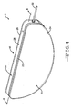
- Fig. 1 is a perspective view showing a capacitor 10 according to the present invention.
- the capacitor 10 comprises an anode 12 (Fig. 2) of an anode active material and a cathode of a cathode active material 14 (Fig. 7) housed inside a hermetically sealed casing 16.
- the capacitor electrodes are operatively associated with each other by a working electrolyte (not shown) contained inside the casing, as will be described in detail hereinafter.
- the capacitor 10 is of an electrolytic type with the cathode comprising a conductive substrate having capacitive properties.
- the casing 16 is of a metal material comprising first and second casing portions 18 and 20.
- Casing portion 18 comprises a surrounding sidewall 22 extending to a face wall 24.
- casing portion 20 comprises a surrounding sidewall 26 extending to a face wall 28.
- Sidewall 26 is sized so that sidewall 22 is in an overlapping relationship therewith. Then, the casing portions 18, 20 are hermetically sealed together by welding the overlapping sidewalls 22, 26 where they contact.
- the weld 30 is provided by any conventional means; however, a preferred method is by laser welding.
- the mating casing portions 18, 20 are preferably selected from the group consisting of tantalum, titanium, nickel, molybdenum, niobium, cobalt, stainless steel, tungsten, platinum, palladium, gold, silver, copper, chromium, vanadium, aluminum, zirconium, hafnium, zinc, iron, and mixtures and alloys thereof.
- the face and sidewalls of the casing portions have a thickness of about 0.005 to about 0.015 inches.
- the active material of the anode 12 is typically of a metal selected from the group consisting of tantalum, aluminum, titanium, niobium, zirconium, hafnium, tungsten, molybdenum, vanadium, silicon, germanium, and mixtures thereof in the form of a pellet.
- the anode metal in powdered form for example tantalum powder, is compressed into a pellet having a notch 32 from which an embedded anode wire 34 (Figs. 2, 4 to 6, 8, 10, 11 and 13) extends.
- the anode wire 34 preferably comprises the same material as the anode active material.
- the anode pellet is sintered under a vacuum at high temperatures and then anodized in a suitable electrolyte.
- the anodizing electrolyte fills the pores of the pressed powder body and a continuous dielectric oxide is formed thereon.
- the anode 12 and extending wire 34 are provided with a dielectric oxide layer formed to a desired working voltage.
- the anode can also be of an etched aluminum, niobium, or titanium foil.
- the dielectric oxide is removed from the wire and there connected to an anode lead 36 supported in an insulative glass-to-metal seal 38 (GTMS).
- GTMS insulative glass-to-metal seal 38
- the weld and lead are then re-anodized.
- the glass-to-metal seal 38 comprises a ferrule 40 defining an internal cylindrical through bore or passage 42 of constant inside diameter.
- An insulative glass 44 provides a hermetic seal between the bore 42 and the anode lead 36 passing there through.
- the anode lead 36 has a J-shaped proximal portion 36A that is subsequently connected to a crook in the anode wire 34 such as by laser welding to secure them together.
- the glass 44 is, for example, ELAN ® type 88 or MANSOL TM type 88. As shown in Figs. 1 and 8, in the final capacitor assembly the GTMS 38 electrically insulates the anode lead 36 connected to the anode wire 34 from the metal casing 18.
- a separator 46 (Fig. 4) of electrically insulative material in the shape of a bag completely surrounds and envelops the anode 12 except the extending wire 34.
- the separator 46 prevents an internal electrical short circuit between the anode 12 and cathode active materials 14 in the assembled capacitor and has a degree of porosity sufficient to allow flow there through of the working electrolyte during the electrochemical reaction of the capacitor 10.
- Illustrative separator materials include woven and non-woven fabrics of polyolefinic fibers including polypropylene and polyethylene or fluoropolymeric fibers including polyvinylidene fluoride, polyethylenetetrafluoroethylene, and polyethylenechlorotrifluoroethylene laminated or superposed with a polyolefinic or fluoropolymeric microporous film, non-woven glass, glass fiber materials and ceramic materials.
- polyolefinic fibers including polypropylene and polyethylene or fluoropolymeric fibers including polyvinylidene fluoride, polyethylenetetrafluoroethylene, and polyethylenechlorotrifluoroethylene laminated or superposed with a polyolefinic or fluoropolymeric microporous film, non-woven glass, glass fiber materials and ceramic materials.
- Suitable microporous films include a polyethylene membrane commercially available under the designation SOLUPOR ® (DMS Solutech), a polytetrafluoroethylene membrane commercially available under the designation ZITEX ® (Chemplast Inc.), a polypropylene membrane commercially available under the designation CELGARD ® (Celanese Plastic Company, Inc.), and a membrane commercially available under the designation DEXIGLAS ® (C. H. Dexter, Div., Dexter Corp.).
- Cellulose based separators also typically used in capacitors are contemplated by the scope of the present invention. Depending on the electrolyte used, the separator can be treated to improve its wettability, as is well known by those skilled in the art.
- the anode 12 connected to the anode lead 36 supported in the GTMS 38 is then positioned inside a fixture 48.
- a metal weld strap 50 is also positioned in the fixture 48 in a generally enclosing, but spaced relationship with the anode 12.
- the weld strap 50 is discontinuous at 52 to provide a space for the GTMS 38.
- the metal strap 50 serves as a backing to protect the anode 12 and separator 46 from laser welding light when the casing portions 18 and 20 are welded to each other during final capacitor assembly.
- a plurality of spacer pegs 54A to 54D are located about the periphery of the anode. The spacer pegs contact both the weld strap and the anode to maintain uniform spacing between them.
- a nozzle 56 is then used to inject a polymeric material at spaced locations between the weld strap 50 and the periphery of the anode sidewall.
- the thusly-formed polymeric restraints 58 are oval-shaped "point contact" structures that each extends a relatively short distance about the periphery of the anode. While oval-shaped structures are shown, that should not be construed as limiting. They can be of many different shapes in plan view as long as the polymeric structures are of a thickness that substantially matches that of the anode between its major face walls.
- the polymeric material of the restraints is of a fast curing type including a polyolefin, a fluoropolymer, a hot melt adhesive, or a UV curable adhesive. A relatively slow curing silastic material is also useful.
- the anode 12 held in position inside the weld strap 50 by the polymeric restraints 58A to 58D is then removed from the fixture 48 as an assembly (Fig. 7).
- the cathode active material 14 preferably coats the face walls 24, 28, spaced from the respective sidewalls 22, 26.
- the pad printing process described in U.S. Patent Application Serial No. 10/920,942, filed August 18, 2004 is preferred for making such a coating.
- Ultrasonically generated aerosol as described in U.S. Patent Nos. 5,894,403 ; 5,920,455 ; 6,224,985 ; and 6,468,605, all to Shah et al. are also suitable deposition methods.
- casing portion 20 is provided with the cathode active material 14 coated on its face wall 28 in a pattern that generally mirrors the shape of the anode 12.
- the cathode active material 14 has a thickness of about a few hundred Angstroms to about 0.1 millimeters and is either directly coated on the inner surface of the face wall 28 or it is coated on a conductive substrate (not shown) in electrical contact with the inner surface of the face wall.
- the other casing portion 18 has the cathode active material 14 similarly coated on its face wall 24 or on a conductive substrate secured to the inner surface of the face wall in electrical contact therewith.
- the face walls 24, 28 may be of an anodized-etched conductive material, have a sintered active material with or without oxide contacted thereto, be contacted with a double layer capacitive material, for example a finely divided carbonaceous material such as graphite or carbon or platinum black, a redox, pseudocapacitive or an under potential material, or be an electroactive conducting polymer such as polyaniline, polypyrole, polythiophene, polyacetylene, and mixtures thereof.
- a double layer capacitive material for example a finely divided carbonaceous material such as graphite or carbon or platinum black, a redox, pseudocapacitive or an under potential material, or be an electroactive conducting polymer such as polyaniline, polypyrole, polythiophene, polyacetylene, and mixtures thereof.
- the redox or cathode active material 14 includes an oxide of a first metal, the nitride of the first metal, the carbon nitride of the first metal, and/or the carbide of the first metal, the oxide, nitride, carbon nitride and carbide having pseudocapacitive properties.
- the first metal is preferably selected from the group consisting of ruthenium, cobalt, manganese, molybdenum, tungsten, tantalum, iron, niobium, iridium, titanium, zirconium, hafnium, rhodium, vanadium, osmium, palladium, platinum, nickel, and lead.
- the cathode active material 14 may also include a second or more metals.
- the second metal is in the form of an oxide, a nitride, a carbon nitride or carbide, and is not essential to the intended use of the conductive face walls 24, 28 as a capacitor electrode.
- the second metal is different than the first metal and is selected from one or more of the group consisting of tantalum, titanium, nickel, iridium, platinum, palladium, gold, silver, cobalt, molybdenum, ruthenium, manganese, tungsten, iron, zirconium, hafnium, rhodium, vanadium, osmium, and niobium.
- the cathode active material 14 includes an oxide of ruthenium or oxides of ruthenium and tantalum.
- the anode 12 held in position by the polymeric restraints 58A to 58D and the weld strap 50 as an assembly is then nested in the casing portion 20 with the GTMS 38 received in an opening 60 (Fig. 8) in the casing sidewall 26.
- the ferrule 40 of the GTMS has a distal step 40A (Fig. 3) that fits into the casing opening 60 in a tight fitting relationship.
- the weld strap 50 is likewise sized to fit inside the perimeter of the casing sidewall 26 in a closely spaced relationship. The ferrule 40 is then secured to the casing sidewall 26 such as by laser welding.
- the other casing portion 18 is then mated to the casing portion 20 with their respective sidewalls 22 and 26 overlapping each other.
- the continuous weldment 30 provided about the perimeter of the casing sidewalls 22 and 26, such as by laser welding, secures the casing portions 18 and 20 to each other.
- the weld strap 50 prevents laser light from penetrating into the interior of the capacitor to damage the anode 12 and separator 46 among other heat sensitive components.
- a working electrolyte (not shown) is then provided in the capacitor through an opening in one of the casing portions 18, 20.
- a suitable working electrolyte for the capacitor 10 is described in U.S. Patent No. 6,219,222 to Shah et al. , which includes a mixed solvent of water and ethylene glycol having an ammonium salt dissolved therein.
- U.S. Pub. Nos. 2003/0090857 and 2003/0142464 describe other working electrolytes for the present capacitors.
- the working electrolyte of the former publication comprises water, a water-soluble inorganic and/or organic acid and/or salt, and a water-soluble nitro-aromatic compound while the latter relates to an electrolyte having de-ionized water, an organic solvent, isobutyric acid and a concentrated ammonium salt.
- These publications and patent are assigned to the assignee of the present invention and incorporated herein by reference.
- the electrolyte fill opening is then closed by a hermetic closure (not shown), as is well known by those skilled in the art.
- the spaces formed between the polymeric restraints 58A to 58D provide for the electrolyte to thoroughly wet the anode 12 including the enveloping separator 46 as well as the cathode active materials 14 to provide the capacitor 10 in a functional state.
- the weld strap 50 encloses and contacts the polymeric restraints 58A to 58D that, in turn, contact the separator 46 at the anode sidewall. This prevents any movement of these components should the capacitor be subject to high shock and vibration conditions.
- the casing 16, including the portions 18, 20, being of a conductive metal serves as the negative terminal for making electrical connection between the capacitor 10 and its load.
- a pin (not shown) is welded to one of the casing portions 18, 20 to provide this.
- the anode lead 36 extending outside the capacitor 10 is hermetically sealed from the interior of the capacitor and insulated from the mating casing portions 20, 22 by the GTMS 38 to serve as the positive terminal for the capacitor 10.
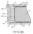
- Fig. 9A shows an alternate embodiment of a casing for the present capacitor.
- the casing comprises portion 20A having a surrounding sidewall 26A extending to a face wall 28A supporting cathode active material 14.
- the sidewall 26A has a step 26B at its upper end that received a plate 24A serving as a second face wall for supporting cathode active material 14.
- the plate 24A is nested in the step 26B.
- a weld 30 secures the plate 24A to the casing portion 20A at the step with the upper surface of the plate being coplanar with the upper end of the sidewall 26A.
- the remaining structure for this capacitor is as previously described.
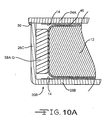
- Figs. 10 and 10A show another embodiment of a casing for the present capacitor.
- the casing comprises portion 20B having a surrounding sidewall 26C extending to a face wall 28B supporting cathode active material 14.
- a plate 24A rests on the upper edge of the sidewall 26C and serves as a second face wall for supporting cathode active material 14. Plate 24A extends a short distance out beyond the sidewall 26C.
- a weld 30 then secures the plate 24A to the casing portion 20B where the plate overhangs or extends past the sidewall 26C.
- the weld strap has been eliminated. Elimination of the weld strap is possible with the laser beam being aimed at the corner where the plate 24A extends past the sidewall 26C. The remaining structure for this capacitor is as previously described.
- Fig. 11 shows an alternate embodiment of a polymeric restraint for a capacitor anode 12.
- the polymeric material 58 completely surrounds the anode sidewall. That is, the polymeric material restrains the anode by contacting the anode sidewall between its major face walls and the sidewall 26C of the casing portion 20B. Since there is no weld strap, the casing is similar to that shown in Figs 10 and 10A. If desired, a weld strap can be provided as previously described.
- the electrolyte wets the anode 12 including the separator 46 and the cathode active material 14 at the opposed face walls.
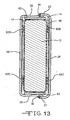
- Figs. 12 and 13 illustrate a further embodiment of the invention.
- the anode 12 is held or restrained in position by a plurality of polymeric structures 62A, 62B and 62C contacting between the separator 46 at each anode face wall and the cathode active material 14 provided at the casing face walls.
- Three polymeric restraints are the preferred minimum number, although more can be provided if desired.
- the polymeric structures 62A to 62C can be used in conjunction with the previously described polymeric restraints provided at the anode sidewall between the opposed anode face walls.
- this embodiment is shown with a weld strap 50, so the casing is similar to that shown in Figs. 1, 7 to 9 and 9A.
- the polymeric structures 62A to 62C can also be provided in a casing similar to that shown in Figs 10 and 10A devoid of a weld strap.
- polymeric restraints 58A to 58D can be used in conjunction with the polymeric restraints 62A to 62C to provide added protection against the anode 12 moving inside the capacitor 10 subjected to high shock and vibration forces.
- the embodiments described herein show the polymeric restraints used with a single anode pellet that should not be construed as limiting. It is contemplate by the scope of the present invention that the polymeric restraints can be used with two or more side-by-side anodes provided in one of the previously described casings. Such a multiple anode design is shown in U.S. patent No. 6,850,405 to Mileham et al. This patent is assigned to the assignee of the present invention and incorporated herein by reference.
Landscapes
- Engineering & Computer Science (AREA)
- Power Engineering (AREA)
- Microelectronics & Electronic Packaging (AREA)
- Fixed Capacitors And Capacitor Manufacturing Machines (AREA)
Abstract
Description
- The present invention generally relates to a capacitor and, more particularly, to a capacitor capable of being subjected to high shock and vibration forces without failing.
- Capacitors are used frequently in applications where high shock and vibration levels are experienced. A notable example is in the oil and gas industry where "measurement while drilling" applications can cause severe stress forces to a capacitor. Under high shock and vibration conditions, capacitors without adequate stabilization are capable of failing due to movement of the electrodes within the case, for example the anode pellet in an electrolytic capacitor. This movement can result in mechanical failure of the anode pellet lead rendering the capacitor inoperative. In that respect, mechanical stabilization of the anode pellet inside the casing is important for improving the reliability and safety of capacitors subjected to high shock and vibration conditions.
- The capacitor of the present invention provides such mechanical stabilization through a plurality of polymeric restraints that contact between the casing sidewall and the anode pellet sidewall to lock the anode in place. Alternatively, the polymeric restraints contact between a weld strap surrounding the butt seam between mating "clam shell" casing portions and the anode pellet sidewall. This structure prevents the anode pellet from moving along both an x- and y-axes. Having the cathode active material coating the opposed major casing sidewalls being in a closely spaced relationship with the anode pellet through an intermediate separator prevents movement along the z-axis.
- These and other aspects of the present invention will become more apparent to those skilled in the art by reference to the following description and to the appended drawings.
-
- Fig. 1 is a perspective view of a
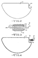
capacitor 10 according to the present invention. - Fig. 2 is a side elevational view of an
anode 12 having an embeddedanode wire 34 extending from anotch 32 thereof. - Fig. 3 is a cross-sectional view of a glass-to-
metal seal 38 for ananode lead 36. - Fig. 4 is a side elevational view of the
anode lead 36 including the glass-to-metal seal 38 connected to the embeddedwire 34 ofanode 12. - Fig. 5 is a plan view of the
anode 12 including the glass-to-metal seal 38 received in afixture 48 surrounded by aweld strap 50 and with polymeric material being injected at selected locations between the anode and weld strap to formrestraints 58A to 58C. - Fig. 6 is a side elevational view showing the
anode 12 held in position inside theweld strap 50 by thepolymeric restraints 58A to 58D. - Fig. 7 is a side elevational view of a
casing portion 20 supporting a cathodeactive material 14 on aface wall 28 thereof. - Fig. 8 is a side elevational view showing the assembly of Fig. 6 comprising the
anode 12,polymeric restraints 58A to 58D andweld strap 50 after having being nested in thecasing portion 20 of Fig. 7. - Fig. 9 is a cross-sectional view of the fully assembled
capacitor 10. - Fig. 9A is an embodiment similar to the view shown in Fig. 9, but with the capacitor housed in different casing.
- Fig. 10 is a side elevational view showing the
anode 12 held in position in a casing portion bypolymeric restraints 58E to 58G, but without a weld strap. - Fig. 10A is a cross-sectional view of Fig. 10.
- Fig. 11 is a side elevational view showing the
anode 12 held in position in a casing portion by a continuouspolymeric restraint 58, but without a weld strap. - Fig. 12 is a side elevational view showing the
anode 12 held in position in a casing portion bypolymeric restraints 62A to 62C at the anode face walls. - Fig. 13 is a cross-sectional view along line 13-13 of Fig. 12.
- Referring now to the drawings, Fig. 1 is a perspective view showing a
capacitor 10 according to the present invention. Thecapacitor 10 comprises an anode 12 (Fig. 2) of an anode active material and a cathode of a cathode active material 14 (Fig. 7) housed inside a hermetically sealedcasing 16. The capacitor electrodes are operatively associated with each other by a working electrolyte (not shown) contained inside the casing, as will be described in detail hereinafter. Thecapacitor 10 is of an electrolytic type with the cathode comprising a conductive substrate having capacitive properties. - As particularly shown in Figs. 1, 7 to 9 and 13, the
casing 16 is of a metal material comprising first andsecond casing portions Casing portion 18 comprises a surroundingsidewall 22 extending to aface wall 24. Similarly,casing portion 20 comprises a surroundingsidewall 26 extending to aface wall 28.Sidewall 26 is sized so thatsidewall 22 is in an overlapping relationship therewith. Then, thecasing portions sidewalls weld 30 is provided by any conventional means; however, a preferred method is by laser welding. - The
mating casing portions - The active material of the
anode 12 is typically of a metal selected from the group consisting of tantalum, aluminum, titanium, niobium, zirconium, hafnium, tungsten, molybdenum, vanadium, silicon, germanium, and mixtures thereof in the form of a pellet. As is well known by those skilled in the art, the anode metal in powdered form, for example tantalum powder, is compressed into a pellet having anotch 32 from which an embedded anode wire 34 (Figs. 2, 4 to 6, 8, 10, 11 and 13) extends. Theanode wire 34 preferably comprises the same material as the anode active material. The anode pellet is sintered under a vacuum at high temperatures and then anodized in a suitable electrolyte. The anodizing electrolyte fills the pores of the pressed powder body and a continuous dielectric oxide is formed thereon. In that manner, theanode 12 and extendingwire 34 are provided with a dielectric oxide layer formed to a desired working voltage. The anode can also be of an etched aluminum, niobium, or titanium foil. - After the
anode 12 and extendingwire 34 are anodized to the desired formation voltage, the dielectric oxide is removed from the wire and there connected to ananode lead 36 supported in an insulative glass-to-metal seal 38 (GTMS). The weld and lead are then re-anodized. The glass-to-metal seal 38 comprises aferrule 40 defining an internal cylindrical through bore orpassage 42 of constant inside diameter. Aninsulative glass 44 provides a hermetic seal between thebore 42 and theanode lead 36 passing there through. Theanode lead 36 has a J-shapedproximal portion 36A that is subsequently connected to a crook in theanode wire 34 such as by laser welding to secure them together. Theglass 44 is, for example, ELAN® type 88 or MANSOL™ type 88. As shown in Figs. 1 and 8, in the final capacitor assembly theGTMS 38 electrically insulates theanode lead 36 connected to theanode wire 34 from themetal casing 18. - A separator 46 (Fig. 4) of electrically insulative material in the shape of a bag completely surrounds and envelops the
anode 12 except the extendingwire 34. Theseparator 46 prevents an internal electrical short circuit between theanode 12 and cathodeactive materials 14 in the assembled capacitor and has a degree of porosity sufficient to allow flow there through of the working electrolyte during the electrochemical reaction of thecapacitor 10. Illustrative separator materials include woven and non-woven fabrics of polyolefinic fibers including polypropylene and polyethylene or fluoropolymeric fibers including polyvinylidene fluoride, polyethylenetetrafluoroethylene, and polyethylenechlorotrifluoroethylene laminated or superposed with a polyolefinic or fluoropolymeric microporous film, non-woven glass, glass fiber materials and ceramic materials. Suitable microporous films include a polyethylene membrane commercially available under the designation SOLUPOR® (DMS Solutech), a polytetrafluoroethylene membrane commercially available under the designation ZITEX® (Chemplast Inc.), a polypropylene membrane commercially available under the designation CELGARD® (Celanese Plastic Company, Inc.), and a membrane commercially available under the designation DEXIGLAS® (C. H. Dexter, Div., Dexter Corp.). Cellulose based separators also typically used in capacitors are contemplated by the scope of the present invention. Depending on the electrolyte used, the separator can be treated to improve its wettability, as is well known by those skilled in the art. - As shown in Fig. 5, the
anode 12 connected to theanode lead 36 supported in theGTMS 38 is then positioned inside afixture 48. Ametal weld strap 50 is also positioned in thefixture 48 in a generally enclosing, but spaced relationship with theanode 12. Theweld strap 50 is discontinuous at 52 to provide a space for theGTMS 38. As will be described in detail hereinafter, themetal strap 50 serves as a backing to protect theanode 12 andseparator 46 from laser welding light when thecasing portions - Once the
anode 12 andGTMS 38 surrounded by theweld strap 50 are properly positioned in thefixture 48, a plurality of spacer pegs 54A to 54D are located about the periphery of the anode. The spacer pegs contact both the weld strap and the anode to maintain uniform spacing between them. - A
nozzle 56 is then used to inject a polymeric material at spaced locations between theweld strap 50 and the periphery of the anode sidewall. The thusly-formedpolymeric restraints 58 are oval-shaped "point contact" structures that each extends a relatively short distance about the periphery of the anode. While oval-shaped structures are shown, that should not be construed as limiting. They can be of many different shapes in plan view as long as the polymeric structures are of a thickness that substantially matches that of the anode between its major face walls. The polymeric material of the restraints is of a fast curing type including a polyolefin, a fluoropolymer, a hot melt adhesive, or a UV curable adhesive. A relatively slow curing silastic material is also useful. Theanode 12 held in position inside theweld strap 50 by thepolymeric restraints 58A to 58D is then removed from thefixture 48 as an assembly (Fig. 7). - The cathode
active material 14 preferably coats theface walls respective sidewalls U.S. Patent Application Serial No. 10/920,942, filed August 18, 2004 U.S. Patent Nos. 5,894,403 ;5,920,455 ;6,224,985 ; and6,468,605, all to Shah et al. , are also suitable deposition methods. These patents and patent application are assigned to the assignee of the present invention and incorporated herein by reference. - As shown in Fig. 7,
casing portion 20 is provided with the cathodeactive material 14 coated on itsface wall 28 in a pattern that generally mirrors the shape of theanode 12. The cathodeactive material 14 has a thickness of about a few hundred Angstroms to about 0.1 millimeters and is either directly coated on the inner surface of theface wall 28 or it is coated on a conductive substrate (not shown) in electrical contact with the inner surface of the face wall. Theother casing portion 18 has the cathodeactive material 14 similarly coated on itsface wall 24 or on a conductive substrate secured to the inner surface of the face wall in electrical contact therewith. In that respect, theface walls - According to one preferred aspect of the present invention, the redox or cathode
active material 14 includes an oxide of a first metal, the nitride of the first metal, the carbon nitride of the first metal, and/or the carbide of the first metal, the oxide, nitride, carbon nitride and carbide having pseudocapacitive properties. The first metal is preferably selected from the group consisting of ruthenium, cobalt, manganese, molybdenum, tungsten, tantalum, iron, niobium, iridium, titanium, zirconium, hafnium, rhodium, vanadium, osmium, palladium, platinum, nickel, and lead. - The cathode
active material 14 may also include a second or more metals. The second metal is in the form of an oxide, a nitride, a carbon nitride or carbide, and is not essential to the intended use of theconductive face walls active material 14 includes an oxide of ruthenium or oxides of ruthenium and tantalum. - As shown in Fig. 8, the
anode 12 held in position by thepolymeric restraints 58A to 58D and theweld strap 50 as an assembly is then nested in thecasing portion 20 with theGTMS 38 received in an opening 60 (Fig. 8) in thecasing sidewall 26. Theferrule 40 of the GTMS has adistal step 40A (Fig. 3) that fits into thecasing opening 60 in a tight fitting relationship. Theweld strap 50 is likewise sized to fit inside the perimeter of thecasing sidewall 26 in a closely spaced relationship. Theferrule 40 is then secured to thecasing sidewall 26 such as by laser welding. This provides theanode 12 secured inside thecasing portion 20 by thepolymeric restraints 58A to 58D and theweld strap 50. In this position, the anode major face wall 12 (Fig. 9) is resting on thecasing sidewall 26. However, theintermediate separator 46 prevents direct contact between theanode 12 and the cathodeactive material 14. - The
other casing portion 18 is then mated to thecasing portion 20 with theirrespective sidewalls continuous weldment 30 provided about the perimeter of the casing sidewalls 22 and 26, such as by laser welding, secures thecasing portions weld strap 50, however, prevents laser light from penetrating into the interior of the capacitor to damage theanode 12 andseparator 46 among other heat sensitive components. - A working electrolyte (not shown) is then provided in the capacitor through an opening in one of the
casing portions capacitor 10 is described inU.S. Patent No. 6,219,222 to Shah et al. , which includes a mixed solvent of water and ethylene glycol having an ammonium salt dissolved therein.U.S. Pub. Nos. 2003/0090857 and2003/0142464 describe other working electrolytes for the present capacitors. The working electrolyte of the former publication comprises water, a water-soluble inorganic and/or organic acid and/or salt, and a water-soluble nitro-aromatic compound while the latter relates to an electrolyte having de-ionized water, an organic solvent, isobutyric acid and a concentrated ammonium salt. These publications and patent are assigned to the assignee of the present invention and incorporated herein by reference. The electrolyte fill opening is then closed by a hermetic closure (not shown), as is well known by those skilled in the art. - The spaces formed between the
polymeric restraints 58A to 58D provide for the electrolyte to thoroughly wet theanode 12 including the envelopingseparator 46 as well as the cathodeactive materials 14 to provide thecapacitor 10 in a functional state. Theweld strap 50 encloses and contacts thepolymeric restraints 58A to 58D that, in turn, contact theseparator 46 at the anode sidewall. This prevents any movement of these components should the capacitor be subject to high shock and vibration conditions. - The
casing 16, including theportions capacitor 10 and its load. A pin (not shown) is welded to one of thecasing portions anode lead 36 extending outside thecapacitor 10 is hermetically sealed from the interior of the capacitor and insulated from themating casing portions GTMS 38 to serve as the positive terminal for thecapacitor 10. - Fig. 9A shows an alternate embodiment of a casing for the present capacitor. The casing comprises
portion 20A having a surroundingsidewall 26A extending to aface wall 28A supporting cathodeactive material 14. Thesidewall 26A has astep 26B at its upper end that received aplate 24A serving as a second face wall for supporting cathodeactive material 14. Theplate 24A is nested in thestep 26B. Aweld 30 secures theplate 24A to thecasing portion 20A at the step with the upper surface of the plate being coplanar with the upper end of thesidewall 26A. The remaining structure for this capacitor is as previously described. - Figs. 10 and 10A show another embodiment of a casing for the present capacitor. The casing comprises
portion 20B having a surroundingsidewall 26C extending to aface wall 28B supporting cathodeactive material 14. Aplate 24A rests on the upper edge of thesidewall 26C and serves as a second face wall for supporting cathodeactive material 14.Plate 24A extends a short distance out beyond thesidewall 26C. Aweld 30 then secures theplate 24A to thecasing portion 20B where the plate overhangs or extends past thesidewall 26C. Also, in this embodiment, the weld strap has been eliminated. Elimination of the weld strap is possible with the laser beam being aimed at the corner where theplate 24A extends past thesidewall 26C. The remaining structure for this capacitor is as previously described. - Fig. 11 shows an alternate embodiment of a polymeric restraint for a
capacitor anode 12. In this embodiment, thepolymeric material 58 completely surrounds the anode sidewall. That is, the polymeric material restrains the anode by contacting the anode sidewall between its major face walls and thesidewall 26C of thecasing portion 20B. Since there is no weld strap, the casing is similar to that shown in Figs 10 and 10A. If desired, a weld strap can be provided as previously described. In this embodiment, the electrolyte wets theanode 12 including theseparator 46 and the cathodeactive material 14 at the opposed face walls. - Figs. 12 and 13 illustrate a further embodiment of the invention. The
anode 12 is held or restrained in position by a plurality ofpolymeric structures separator 46 at each anode face wall and the cathodeactive material 14 provided at the casing face walls. Three polymeric restraints are the preferred minimum number, although more can be provided if desired. Also, thepolymeric structures 62A to 62C can be used in conjunction with the previously described polymeric restraints provided at the anode sidewall between the opposed anode face walls. Finally, this embodiment is shown with aweld strap 50, so the casing is similar to that shown in Figs. 1, 7 to 9 and 9A. Thepolymeric structures 62A to 62C can also be provided in a casing similar to that shown in Figs 10 and 10A devoid of a weld strap. - Thus, various polymeric structures as point restraints have been shown and described. However, modifications may be readily apparent to those skilled in the art. For example, the
polymeric restraints 58A to 58D can be used in conjunction with thepolymeric restraints 62A to 62C to provide added protection against theanode 12 moving inside thecapacitor 10 subjected to high shock and vibration forces. - Although the embodiments described herein show the polymeric restraints used with a single anode pellet that should not be construed as limiting. It is contemplate by the scope of the present invention that the polymeric restraints can be used with two or more side-by-side anodes provided in one of the previously described casings. Such a multiple anode design is shown in
U.S. patent No. 6,850,405 to Mileham et al. This patent is assigned to the assignee of the present invention and incorporated herein by reference. - It is appreciated that various modifications to the inventive concepts described herein may be apparent to those of ordinary skill in the art without departing from the spirit and scope of the present invention as defined by the appended claims.
Claims (19)
- A capacitor (10), which comprises:a) a first casing portion (18) comprising a first casing face wall (24) supporting a first surrounding casing sidewall (22) and a second casing portion (20) comprising a second casing face wall (28), wherein the first casing portion (18) is securable to the second casing portion (20) to provide an enclosure for the capacitor (10);b) a cathode active material (14) supported by, and in electrical contact with, the first and second casing face walls (24, 28);c) an anode (12) comprising an anode sidewall extending to first and second major anode face walls positioned adjacent to the cathode active material (14) on the first and second casing face walls (24, 28);d) a separator (46) positioned intermediate the anode (12) and the cathode active material (14) on the first and second casing face walls (24, 28);e) a glass-to-metal seal (38) supported in at least one of the first and second casing portions (18, 20) to electrically insulate the anode lead (36) from the enclosure serving as the cathode terminal;f) at least one restraint (58) contacting the anode sidewall to prevent the anode (12) from moving inside the enclosure when the capacitor (10) is subjected to shock and vibration forces; andg) a working electrolyte provided in the enclosure in contact with the anode (12) and cathode active material (14).
- The capacitor (10) of claim 1, wherein the restraint (58) is of a polymeric material selected from the group consisting of a polyolefin, a fluoropolymer, a hot melt adhesive, a UV curable adhesive and a silastic material.
- The capacitor (10) of claim 1 or claim 2 wherein the restraint (58) is continuous about the anode sidewall.
- The capacitor (10) of any of claims 1 to 3, wherein the restraint (58) contacts the anode sidewall and a weld strap (50) provided between where the first casing portion (18) is secured to the second casing portion (20) .
- The capacitor (10) of any of claims 1 to 4, wherein the restraint (58) contacts the anode sidewall and the first casing sidewall (22).
- The capacitor (10) of any of claims 1 to 5, wherein there are a plurality of point restraints (58) that each contact the anode sidewall and a weld strap (50) provided between where the first casing portion (18) is secured to the second casing portion (20).
- The capacitor (10) of any of claims 1 to 6, wherein the second casing portion (20) is a plate supported at an upper edge of the first casing sidewall (22) of the first casing portion (18).
- The capacitor (10) of any of claims 1 to 7, wherein the material of the anode (12) is selected from the group consisting of tantalum, aluminum, titanium, niobium, zirconium, hafnium, tungsten, molybdenum, vanadium, silicon, germanium, and mixtures thereof and the cathode active material (14) is selected from the group consisting of ruthenium, cobalt, manganese, molybdenum, tungsten, tantalum, iron, niobium, iridium, titanium, zirconium, hafnium, rhodium, vanadium, osmium, palladium, platinum, nickel, lead, gold, silver, and mixtures thereof.
- The capacitor (10) of any of claims 1 to 8, wherein the cathode active material (14) is selected from an oxide, a nitride, a carbon nitride and a carbide of one of the group consisting of ruthenium, cobalt, manganese, molybdenum, tungsten, tantalum, iron, niobium, iridium, titanium, zirconium, hafnium, rhodium, vanadium, osmium, palladium, platinum, nickel, and lead
- A capacitor (10), which comprises:a) a first casing portion (18) comprising a first casing face wall (24) supporting a first surrounding casing sidewall (22) and a second casing portion (20) comprising a second casing face wall (28) supporting a second surrounding casing sidewall (26), wherein at least a portion of the first casing sidewall (22) is sized to fit inside the second casing sidewall (26) to mate the first casing portion (18) with the second casing portion (20) as an enclosure for the capacitor (10);b) a cathode active material (14) supported by, and in electrical contact with, the first and second casing face walls (24,28) of the enclosure;c) an anode (12) comprising an anode sidewall extending to first and second major anode face walls positioned adjacent to the cathode active material (14) on the first and second casing face walls (24, 28);d) a separator (46) positioned intermediate the anode (12) and the cathode active material (14) on the first and second casing face walls (24, 28);e) a glass-to-metal seal supported in at least one of the first and second casing portions (18, 20) to electrically insulate the anode lead from the enclosure serving as the cathode terminal;f) at least one point restraint (58) contacting the anode sidewall to prevent the anode (12) from moving inside the enclosure when the capacitor (10) is subjected to shock and vibration forces; andg) a working electrolyte provided in the enclosure in contact with the anode (12) and cathode active material (14).
- The capacitor (10) of claim 10, wherein the restraint (58) is continuous about the anode sidewall.
- The capacitor (10) of claim 10 or claim 11, wherein the restraint (58) contacts the anode sidewall and a weld strap (50) provided between where the first casing portion (18) is secured to the second casing portion (20).
- The capacitor (10) of any of claims 10 to 12, wherein the restraint (58) contacts the anode sidewall and the first casing sidewall (22).
- The capacitor (10) of any of claims 10 to 13, wherein there are a plurality of point restraints (58) that contact the anode sidewall and a weld strap (50) provided between a seam created by the first surrounding sidewall (22) of the first casing portion (18) mated to the second surrounding sidewall (26) of the second casing portion (20).
- A method for providing a capacitor (10), comprising the steps of:a) providing a first casing portion (18) comprising a first casing face wall (24) supporting a first surrounding casing sidewall (22), wherein a cathode active material (14) is in electrical contact with the first casing face wall (24);b) providing an anode (12) comprising an anode sidewall extending to first and second major casing face walls (24, 28), wherein an anode wire (34) extends from the anode (12);c) supporting an anode lead (36) in a glass-to-metal seal (38) and connecting the anode lead (36) to the anode wire (34);d) enveloping the anode (12) in a separator (46);e) providing a weld strap (50) in a surrounding but spaced relationship with the anode sidewall;f) providing a plurality of point restraints (58) contacting between the anode sidewall and the weld strap (50);g) nesting the anode (12) including the restraints (58) and the weld strap (50) in the first casing portion (18) with the first major anode face wall adjacent to the cathode active material (14) and wherein the glass-to-metal seal (38) is at least partially supported by the first casing sidewall (22) with the anode lead (36) extending there from;h) providing a second casing portion (20) comprising a second casing face wall (28) having the cathode active material (14) in electrical contact there with and adjacent to the second major anode face wall;i) welding the first casing portion (18) to the second casing portion (20) to provide an enclosure for the capacitor (10); andj) providing an electrolyte in the enclosure in contact with the anode (12) and cathode active material (14).
- The method of claim 15, including providing the restraints (58) of a polymeric material selected from the group consisting of a polyolefin, a fluoropolymer, a hot melt adhesive, a UV curable adhesive and a silastic material.
- The method of claim 15 or claim 16, including positioning the anode (12) enveloped by the separator (46) in a fixture interior of the weld strap (50) and then providing a plurality of spacers (54) about the anode (12) contacting the separator (46) at the anode sidewall restraints.
- The method of claim 17, including injecting a polymeric material into the fixture at spaced locations about the periphery of the anode (12) to provide the restraints (58).
- The method of any of claims 15 to 18, including nesting the anode (12) having the plurality of restraints (58) contacting an inner surface of the weld strap (50) with the weld strap (50) contacting at least one of the first and second casing portions (18,20).
Applications Claiming Priority (1)
| Application Number | Priority Date | Filing Date | Title |
|---|---|---|---|
| US11/222,259 US7092242B1 (en) | 2005-09-08 | 2005-09-08 | Polymeric restraints for containing an anode in an electrolytic capacitor from high shock and vibration conditions |
Publications (2)
| Publication Number | Publication Date |
|---|---|
| EP1763045A1 true EP1763045A1 (en) | 2007-03-14 |
| EP1763045B1 EP1763045B1 (en) | 2009-11-11 |
Family
ID=36781799
Family Applications (1)
| Application Number | Title | Priority Date | Filing Date |
|---|---|---|---|
| EP06018325A Not-in-force EP1763045B1 (en) | 2005-09-08 | 2006-09-01 | Polymeric restraints for containing an anode in an electrolytic capacitor from high shock and vibration conditions |
Country Status (3)
| Country | Link |
|---|---|
| US (1) | US7092242B1 (en) |
| EP (1) | EP1763045B1 (en) |
| DE (1) | DE602006010290D1 (en) |
Cited By (3)
| Publication number | Priority date | Publication date | Assignee | Title |
|---|---|---|---|---|
| FR2973929A1 (en) * | 2011-04-07 | 2012-10-12 | Avx Corp | MANGANESE OXIDE CAPACITOR FOR USE IN EXTREME ENVIRONMENTS |
| FR2973928A1 (en) * | 2011-04-07 | 2012-10-12 | Avx Corp | HERMETICALLY SEALED ELECTROLYTIC CAPACITOR WITH IMPROVED MECHANICAL STABILITY |
| FR3031230A1 (en) * | 2014-12-30 | 2016-07-01 | Avx Corp | WET ELECTROLYTE CAPACITOR CONTAINING EVIDED PLANAR ANODE AND RETENTION |
Families Citing this family (39)
| Publication number | Priority date | Publication date | Assignee | Title |
|---|---|---|---|---|
| US7092242B1 (en) * | 2005-09-08 | 2006-08-15 | Greatbatch, Inc. | Polymeric restraints for containing an anode in an electrolytic capacitor from high shock and vibration conditions |
| US20070231681A1 (en) * | 2006-03-31 | 2007-10-04 | Casby Kurt J | Immobilization system for an electrochemical cell |
| EP1903584A1 (en) | 2006-09-20 | 2008-03-26 | Greatbatch Ltd. | Flat sealing of anode/separator assembly for use in capacitors |
| US7483260B2 (en) * | 2006-12-22 | 2009-01-27 | Greatbatch Ltd. | Dual anode capacitor with internally connected anodes |
| US7813107B1 (en) * | 2007-03-15 | 2010-10-12 | Greatbatch Ltd. | Wet tantalum capacitor with multiple anode connections |
| US7649730B2 (en) | 2007-03-20 | 2010-01-19 | Avx Corporation | Wet electrolytic capacitor containing a plurality of thin powder-formed anodes |
| US7554792B2 (en) | 2007-03-20 | 2009-06-30 | Avx Corporation | Cathode coating for a wet electrolytic capacitor |
| US7460356B2 (en) | 2007-03-20 | 2008-12-02 | Avx Corporation | Neutral electrolyte for a wet electrolytic capacitor |
| US8023250B2 (en) * | 2008-09-12 | 2011-09-20 | Avx Corporation | Substrate for use in wet capacitors |
| US8279585B2 (en) * | 2008-12-09 | 2012-10-02 | Avx Corporation | Cathode for use in a wet capacitor |
| US8223473B2 (en) | 2009-03-23 | 2012-07-17 | Avx Corporation | Electrolytic capacitor containing a liquid electrolyte |
| US8605411B2 (en) | 2010-09-16 | 2013-12-10 | Avx Corporation | Abrasive blasted conductive polymer cathode for use in a wet electrolytic capacitor |
| US8514547B2 (en) | 2010-11-01 | 2013-08-20 | Avx Corporation | Volumetrically efficient wet electrolytic capacitor |
| US8259435B2 (en) | 2010-11-01 | 2012-09-04 | Avx Corporation | Hermetically sealed wet electrolytic capacitor |
| US9767964B2 (en) | 2011-04-07 | 2017-09-19 | Avx Corporation | Multi-anode solid electrolytic capacitor assembly |
| US8974949B2 (en) | 2011-04-07 | 2015-03-10 | Cardiac Pacemakers, Inc. | Electrical insulator shaped to conform to power source electrodes |
| US8451586B2 (en) | 2011-09-13 | 2013-05-28 | Avx Corporation | Sealing assembly for a wet electrolytic capacitor |
| US9129747B2 (en) | 2012-03-16 | 2015-09-08 | Avx Corporation | Abrasive blasted cathode of a wet electrolytic capacitor |
| US9312075B1 (en) | 2013-09-06 | 2016-04-12 | Greatbatch Ltd. | High voltage tantalum anode and method of manufacture |
| US9633796B2 (en) | 2013-09-06 | 2017-04-25 | Greatbatch Ltd. | High voltage tantalum anode and method of manufacture |
| USRE48439E1 (en) | 2013-09-06 | 2021-02-16 | Greatbatch Ltd. | High voltage tantalum anode and method of manufacture |
| US9620293B2 (en) * | 2014-11-17 | 2017-04-11 | Avx Corporation | Hermetically sealed capacitor for an implantable medical device |
| US20170125178A1 (en) | 2015-10-30 | 2017-05-04 | Greatbatch Ltd. | High voltage dual anode tantalum capacitor with facing casing clamshells contacting an intermediate partition |
| US9875855B2 (en) | 2015-10-30 | 2018-01-23 | Greatbatch Ltd. | High voltage tantalum capacitor with improved cathode/separator design and method of manufacture |
| US9978528B2 (en) | 2015-11-20 | 2018-05-22 | Greatbatch Ltd. | High voltage capacitor having a dual tantalum anode/cathode current collector electrode assembly housed in a dual separator envelope design |
| US10176930B2 (en) | 2016-01-14 | 2019-01-08 | Vishay Sprague, Inc. | Low profile flat wet electrolytic tantalum capacitor |
| US10283275B2 (en) | 2016-05-20 | 2019-05-07 | Greatbatch Ltd. | Feedthrough seal apparatus, system, and method |
| US9870869B1 (en) | 2016-06-28 | 2018-01-16 | Avx Corporation | Wet electrolytic capacitor |
| US9870868B1 (en) | 2016-06-28 | 2018-01-16 | Avx Corporation | Wet electrolytic capacitor for use in a subcutaneous implantable cardioverter-defibrillator |
| EP3895832B1 (en) | 2016-08-12 | 2022-12-28 | COMPOSITE MATERIALS TECHNOLOGY, Inc. | Electrolytic capacitor and method for improved electrolytic capacitor anodes |
| CN109562950B (en) | 2016-09-01 | 2020-05-19 | 复合材料技术公司 | Nanoscale/Nanostructured Si Coatings on Valve Metal Substrates for LIB Anodes |
| US9721730B1 (en) | 2017-03-03 | 2017-08-01 | Greatbatch Ltd. | Capacitor having multiple anodes housed in a stacked casing |
| EP3534385A1 (en) | 2018-03-02 | 2019-09-04 | Greatbatch Ltd. | Titanium clad nickel termination-pad welded to a titanium tab for a capacitor |
| US11189431B2 (en) | 2018-07-16 | 2021-11-30 | Vishay Sprague, Inc. | Low profile wet electrolytic tantalum capacitor |
| US11450486B2 (en) | 2020-04-03 | 2022-09-20 | Greatbatch Ltd. | Electrolytic capacitor having a tantalum anode |
| US12119186B2 (en) | 2020-04-03 | 2024-10-15 | Greatbatch Ltd. | Electrolytic capacitor having an anode formed from a tantalum powder with a relatively low specific charge |
| US11462363B2 (en) | 2020-12-29 | 2022-10-04 | Greatbatch Ltd. | Electrolytic capacitor having a shaped anode wire that prevents failure due to a cracked anode |
| US11742149B2 (en) * | 2021-11-17 | 2023-08-29 | Vishay Israel Ltd. | Hermetically sealed high energy electrolytic capacitor and capacitor assemblies with improved shock and vibration performance |
| USD1120880S1 (en) | 2024-05-31 | 2026-03-31 | Vishay Israel Ltd. | Base for a capacitor |
Citations (2)
| Publication number | Priority date | Publication date | Assignee | Title |
|---|---|---|---|---|
| EP1571681A1 (en) | 2004-03-01 | 2005-09-07 | Wilson Greatbatch Technologies, Inc. | Molded polymeric cradle for containing an anode in an electrolytic capacitor for use in high shock and vibration conditions |
| US7092242B1 (en) * | 2005-09-08 | 2006-08-15 | Greatbatch, Inc. | Polymeric restraints for containing an anode in an electrolytic capacitor from high shock and vibration conditions |
Family Cites Families (21)
| Publication number | Priority date | Publication date | Assignee | Title |
|---|---|---|---|---|
| US3697823A (en) | 1971-11-03 | 1972-10-10 | Gen Electric | Metal-to-glass-to-metal hermetic seal |
| US4208699A (en) * | 1975-09-02 | 1980-06-17 | Sangamo Weston, Inc. | Capacitor with molded header including strengthening material |
| JPH10106898A (en) * | 1996-09-27 | 1998-04-24 | Rohm Co Ltd | Structure of capacitor element using for solid electrolytic capacitor and slid forming method for chip body of the capacitor element |
| US5894403A (en) | 1997-05-01 | 1999-04-13 | Wilson Greatbatch Ltd. | Ultrasonically coated substrate for use in a capacitor |
| US5920455A (en) | 1997-05-01 | 1999-07-06 | Wilson Greatbatch Ltd. | One step ultrasonically coated substrate for use in a capacitor |
| US5926362A (en) | 1997-05-01 | 1999-07-20 | Wilson Greatbatch Ltd. | Hermetically sealed capacitor |
| US5870272A (en) | 1997-05-06 | 1999-02-09 | Medtronic Inc. | Capacitive filter feedthrough for implantable medical device |
| ATE350757T1 (en) | 1998-08-28 | 2007-01-15 | Greatbatch W Ltd | ELECTROLYTE FOR A CAPACITOR |
| GB9824442D0 (en) | 1998-11-06 | 1999-01-06 | Avx Ltd | Manufacture of solid state capacitors |
| US6297943B1 (en) | 1999-03-19 | 2001-10-02 | Pacesetter, Inc. | Capacitor with thermosealed polymeric case for implantable medical device |
| JP4547835B2 (en) | 2001-06-21 | 2010-09-22 | パナソニック株式会社 | Solid electrolytic capacitor and manufacturing method thereof |
| JP2003197468A (en) | 2001-10-19 | 2003-07-11 | Nec Tokin Toyama Ltd | Solid electrolytic capacitor and manufacturing method therefor |
| JP2003234250A (en) | 2001-11-14 | 2003-08-22 | Wilson Greatbatch Technologies Inc | Depolarizer for hybrid capacitors |
| MY133582A (en) | 2001-12-18 | 2007-11-30 | Matsushita Electric Industrial Co Ltd | Aluminum electrolytic capacitor and method for producing the same |
| JP2003249422A (en) | 2001-12-18 | 2003-09-05 | Matsushita Electric Ind Co Ltd | Aluminum electrolytic capacitor and method of manufacturing the same |
| US6687117B2 (en) | 2002-01-31 | 2004-02-03 | Wilson Greatbatch Technologies, Inc. | Electrolytes for capacitors |
| CA2446476A1 (en) | 2002-02-28 | 2003-09-04 | Greatbatch-Sierra, Inc. | Emi feedthrough filter terminal assembly utilizing hermetic seal for electrical attachment between lead wires and capacitor |
| EP1431990A3 (en) | 2002-12-16 | 2006-04-26 | Wilson Greatbatch Technologies, Inc. | Dual anode capacitor |
| US6859353B2 (en) | 2002-12-16 | 2005-02-22 | Wilson Greatbatch Technologies, Inc. | Capacitor interconnect design |
| JP2004304010A (en) * | 2003-03-31 | 2004-10-28 | Rubycon Corp | Flat aluminium electrolytic capacitor and its manufacturing method |
| US7085126B2 (en) * | 2004-03-01 | 2006-08-01 | Wilson Greatbatch Technologies, Inc. | Molded polymeric cradle for containing an anode in an electrolytic capacitor from high shock and vibration conditions |
-
2005
- 2005-09-08 US US11/222,259 patent/US7092242B1/en not_active Expired - Lifetime
-
2006
- 2006-09-01 EP EP06018325A patent/EP1763045B1/en not_active Not-in-force
- 2006-09-01 DE DE602006010290T patent/DE602006010290D1/en active Active
Patent Citations (2)
| Publication number | Priority date | Publication date | Assignee | Title |
|---|---|---|---|---|
| EP1571681A1 (en) | 2004-03-01 | 2005-09-07 | Wilson Greatbatch Technologies, Inc. | Molded polymeric cradle for containing an anode in an electrolytic capacitor for use in high shock and vibration conditions |
| US7092242B1 (en) * | 2005-09-08 | 2006-08-15 | Greatbatch, Inc. | Polymeric restraints for containing an anode in an electrolytic capacitor from high shock and vibration conditions |
Cited By (3)
| Publication number | Priority date | Publication date | Assignee | Title |
|---|---|---|---|---|
| FR2973929A1 (en) * | 2011-04-07 | 2012-10-12 | Avx Corp | MANGANESE OXIDE CAPACITOR FOR USE IN EXTREME ENVIRONMENTS |
| FR2973928A1 (en) * | 2011-04-07 | 2012-10-12 | Avx Corp | HERMETICALLY SEALED ELECTROLYTIC CAPACITOR WITH IMPROVED MECHANICAL STABILITY |
| FR3031230A1 (en) * | 2014-12-30 | 2016-07-01 | Avx Corp | WET ELECTROLYTE CAPACITOR CONTAINING EVIDED PLANAR ANODE AND RETENTION |
Also Published As
| Publication number | Publication date |
|---|---|
| EP1763045B1 (en) | 2009-11-11 |
| DE602006010290D1 (en) | 2009-12-24 |
| US7092242B1 (en) | 2006-08-15 |
Similar Documents
| Publication | Publication Date | Title |
|---|---|---|
| EP1763045B1 (en) | Polymeric restraints for containing an anode in an electrolytic capacitor from high shock and vibration conditions | |
| US7085126B2 (en) | Molded polymeric cradle for containing an anode in an electrolytic capacitor from high shock and vibration conditions | |
| EP1592031B1 (en) | Flat back case for an electrolytic capacitor | |
| US7271994B2 (en) | Energy dense electrolytic capacitor | |
| US7983022B2 (en) | Electrically connecting multiple cathodes in a case negative multi-anode capacitor | |
| JP4726784B2 (en) | Insulating feedthrough assembly for electrochemical devices | |
| EP1936643B1 (en) | Capacitor with a plurality of internally connected anodes | |
| EP1818957B1 (en) | Electrolytic capacitor capable of insertion into the vasculature of a patient | |
| EP3171378B1 (en) | High voltage capacitor having a dual tantalum anode/cathode current collector electrode assembly housed in a dual separator envelope design | |
| US6859353B2 (en) | Capacitor interconnect design | |
| US6850405B1 (en) | Dual anode capacitor interconnect design | |
| EP2117021B1 (en) | Electrolytic capacitors with multiple anodes and anode lead configurations thereof | |
| US6967829B2 (en) | Capacitor interconnect design | |
| EP3163593B1 (en) | High voltage tantalum capacitor with improved cathode/separator design | |
| US8081419B2 (en) | Interconnections for multiple capacitor anode leads | |
| EP3166117A1 (en) | High voltage dual anode tantalum capacitor with facing casing clamshells contacting an intermediate partition | |
| EP1571681B1 (en) | Molded polymeric cradle for containing an anode in an electrolytic capacitor for use in high shock and vibration conditions | |
| US11195665B2 (en) | Titanium clad nickel termination-pad welded to a titanium tab for a capacitor | |
| HK1192645B (en) | Hermetically sealed electrolytic capacitor |
Legal Events
| Date | Code | Title | Description |
|---|---|---|---|
| PUAI | Public reference made under article 153(3) epc to a published international application that has entered the european phase |
Free format text: ORIGINAL CODE: 0009012 |
|
| AK | Designated contracting states |
Kind code of ref document: A1 Designated state(s): AT BE BG CH CY CZ DE DK EE ES FI FR GB GR HU IE IS IT LI LT LU LV MC NL PL PT RO SE SI SK TR |
|
| AX | Request for extension of the european patent |
Extension state: AL BA HR MK YU |
|
| 17P | Request for examination filed |
Effective date: 20070914 |
|
| AKX | Designation fees paid |
Designated state(s): DE FR IT SE |
|
| RAP1 | Party data changed (applicant data changed or rights of an application transferred) |
Owner name: GREATBATCH LTD. |
|
| RAP1 | Party data changed (applicant data changed or rights of an application transferred) |
Owner name: GREATBATCH LTD. |
|
| GRAP | Despatch of communication of intention to grant a patent |
Free format text: ORIGINAL CODE: EPIDOSNIGR1 |
|
| GRAS | Grant fee paid |
Free format text: ORIGINAL CODE: EPIDOSNIGR3 |
|
| GRAA | (expected) grant |
Free format text: ORIGINAL CODE: 0009210 |
|
| AK | Designated contracting states |
Kind code of ref document: B1 Designated state(s): DE FR IT SE |
|
| REF | Corresponds to: |
Ref document number: 602006010290 Country of ref document: DE Date of ref document: 20091224 Kind code of ref document: P |
|
| REG | Reference to a national code |
Ref country code: SE Ref legal event code: TRGR |
|
| PLBE | No opposition filed within time limit |
Free format text: ORIGINAL CODE: 0009261 |
|
| STAA | Information on the status of an ep patent application or granted ep patent |
Free format text: STATUS: NO OPPOSITION FILED WITHIN TIME LIMIT |
|
| 26N | No opposition filed |
Effective date: 20100812 |
|
| PGFP | Annual fee paid to national office [announced via postgrant information from national office to epo] |
Ref country code: IT Payment date: 20100923 Year of fee payment: 5 |
|
| PGFP | Annual fee paid to national office [announced via postgrant information from national office to epo] |
Ref country code: SE Payment date: 20100929 Year of fee payment: 5 |
|
| PG25 | Lapsed in a contracting state [announced via postgrant information from national office to epo] |
Ref country code: IT Free format text: LAPSE BECAUSE OF NON-PAYMENT OF DUE FEES Effective date: 20110901 |
|
| REG | Reference to a national code |
Ref country code: SE Ref legal event code: EUG |
|
| PG25 | Lapsed in a contracting state [announced via postgrant information from national office to epo] |
Ref country code: SE Free format text: LAPSE BECAUSE OF NON-PAYMENT OF DUE FEES Effective date: 20110902 |
|
| REG | Reference to a national code |
Ref country code: DE Ref legal event code: R082 Ref document number: 602006010290 Country of ref document: DE Representative=s name: SSM SANDMAIR PATENTANWAELTE RECHTSANWALT PARTN, DE Ref country code: DE Ref legal event code: R082 Ref document number: 602006010290 Country of ref document: DE Representative=s name: SCHWABE SANDMAIR MARX PATENTANWAELTE RECHTSANW, DE |
|
| REG | Reference to a national code |
Ref country code: FR Ref legal event code: PLFP Year of fee payment: 11 |
|
| REG | Reference to a national code |
Ref country code: FR Ref legal event code: PLFP Year of fee payment: 12 |
|
| REG | Reference to a national code |
Ref country code: FR Ref legal event code: PLFP Year of fee payment: 13 |
|
| PGFP | Annual fee paid to national office [announced via postgrant information from national office to epo] |
Ref country code: FR Payment date: 20180813 Year of fee payment: 13 Ref country code: DE Payment date: 20180821 Year of fee payment: 13 |
|
| REG | Reference to a national code |
Ref country code: DE Ref legal event code: R119 Ref document number: 602006010290 Country of ref document: DE |
|
| PG25 | Lapsed in a contracting state [announced via postgrant information from national office to epo] |
Ref country code: DE Free format text: LAPSE BECAUSE OF NON-PAYMENT OF DUE FEES Effective date: 20200401 |
|
| PG25 | Lapsed in a contracting state [announced via postgrant information from national office to epo] |
Ref country code: FR Free format text: LAPSE BECAUSE OF NON-PAYMENT OF DUE FEES Effective date: 20190930 |