EP1762767A2 - Pressure line - Google Patents
Pressure line Download PDFInfo
- Publication number
- EP1762767A2 EP1762767A2 EP06018187A EP06018187A EP1762767A2 EP 1762767 A2 EP1762767 A2 EP 1762767A2 EP 06018187 A EP06018187 A EP 06018187A EP 06018187 A EP06018187 A EP 06018187A EP 1762767 A2 EP1762767 A2 EP 1762767A2
- Authority
- EP
- European Patent Office
- Prior art keywords
- pressure line
- plastic tube
- connector according
- plastic
- hydraulic system
- Prior art date
- Legal status (The legal status is an assumption and is not a legal conclusion. Google has not performed a legal analysis and makes no representation as to the accuracy of the status listed.)
- Ceased
Links
Images


Classifications
-
- F—MECHANICAL ENGINEERING; LIGHTING; HEATING; WEAPONS; BLASTING
- F16—ENGINEERING ELEMENTS AND UNITS; GENERAL MEASURES FOR PRODUCING AND MAINTAINING EFFECTIVE FUNCTIONING OF MACHINES OR INSTALLATIONS; THERMAL INSULATION IN GENERAL
- F16L—PIPES; JOINTS OR FITTINGS FOR PIPES; SUPPORTS FOR PIPES, CABLES OR PROTECTIVE TUBING; MEANS FOR THERMAL INSULATION IN GENERAL
- F16L21/00—Joints with sleeve or socket
- F16L21/02—Joints with sleeve or socket with elastic sealing rings between pipe and sleeve or between pipe and socket, e.g. with rolling or other prefabricated profiled rings
- F16L21/035—Joints with sleeve or socket with elastic sealing rings between pipe and sleeve or between pipe and socket, e.g. with rolling or other prefabricated profiled rings placed around the spigot end before connection
-
- F—MECHANICAL ENGINEERING; LIGHTING; HEATING; WEAPONS; BLASTING
- F16—ENGINEERING ELEMENTS AND UNITS; GENERAL MEASURES FOR PRODUCING AND MAINTAINING EFFECTIVE FUNCTIONING OF MACHINES OR INSTALLATIONS; THERMAL INSULATION IN GENERAL
- F16D—COUPLINGS FOR TRANSMITTING ROTATION; CLUTCHES; BRAKES
- F16D23/00—Details of mechanically-actuated clutches not specific for one distinct type
- F16D23/12—Mechanical clutch-actuating mechanisms arranged outside the clutch as such
-
- F—MECHANICAL ENGINEERING; LIGHTING; HEATING; WEAPONS; BLASTING
- F16—ENGINEERING ELEMENTS AND UNITS; GENERAL MEASURES FOR PRODUCING AND MAINTAINING EFFECTIVE FUNCTIONING OF MACHINES OR INSTALLATIONS; THERMAL INSULATION IN GENERAL
- F16D—COUPLINGS FOR TRANSMITTING ROTATION; CLUTCHES; BRAKES
- F16D25/00—Fluid-actuated clutches
- F16D25/08—Fluid-actuated clutches with fluid-actuated member not rotating with a clutching member
- F16D25/088—Fluid-actuated clutches with fluid-actuated member not rotating with a clutching member the line of action of the fluid-actuated members being distinctly separate from the axis of rotation
-
- F—MECHANICAL ENGINEERING; LIGHTING; HEATING; WEAPONS; BLASTING
- F16—ENGINEERING ELEMENTS AND UNITS; GENERAL MEASURES FOR PRODUCING AND MAINTAINING EFFECTIVE FUNCTIONING OF MACHINES OR INSTALLATIONS; THERMAL INSULATION IN GENERAL
- F16D—COUPLINGS FOR TRANSMITTING ROTATION; CLUTCHES; BRAKES
- F16D48/00—External control of clutches
- F16D48/02—Control by fluid pressure
-
- F—MECHANICAL ENGINEERING; LIGHTING; HEATING; WEAPONS; BLASTING
- F16—ENGINEERING ELEMENTS AND UNITS; GENERAL MEASURES FOR PRODUCING AND MAINTAINING EFFECTIVE FUNCTIONING OF MACHINES OR INSTALLATIONS; THERMAL INSULATION IN GENERAL
- F16L—PIPES; JOINTS OR FITTINGS FOR PIPES; SUPPORTS FOR PIPES, CABLES OR PROTECTIVE TUBING; MEANS FOR THERMAL INSULATION IN GENERAL
- F16L11/00—Hoses, i.e. flexible pipes
- F16L11/04—Hoses, i.e. flexible pipes made of rubber or flexible plastics
-
- F—MECHANICAL ENGINEERING; LIGHTING; HEATING; WEAPONS; BLASTING
- F16—ENGINEERING ELEMENTS AND UNITS; GENERAL MEASURES FOR PRODUCING AND MAINTAINING EFFECTIVE FUNCTIONING OF MACHINES OR INSTALLATIONS; THERMAL INSULATION IN GENERAL
- F16L—PIPES; JOINTS OR FITTINGS FOR PIPES; SUPPORTS FOR PIPES, CABLES OR PROTECTIVE TUBING; MEANS FOR THERMAL INSULATION IN GENERAL
- F16L21/00—Joints with sleeve or socket
- F16L21/08—Joints with sleeve or socket with additional locking means
-
- F—MECHANICAL ENGINEERING; LIGHTING; HEATING; WEAPONS; BLASTING
- F16—ENGINEERING ELEMENTS AND UNITS; GENERAL MEASURES FOR PRODUCING AND MAINTAINING EFFECTIVE FUNCTIONING OF MACHINES OR INSTALLATIONS; THERMAL INSULATION IN GENERAL
- F16L—PIPES; JOINTS OR FITTINGS FOR PIPES; SUPPORTS FOR PIPES, CABLES OR PROTECTIVE TUBING; MEANS FOR THERMAL INSULATION IN GENERAL
- F16L37/00—Couplings of the quick-acting type
- F16L37/08—Couplings of the quick-acting type in which the connection between abutting or axially overlapping ends is maintained by locking members
- F16L37/084—Couplings of the quick-acting type in which the connection between abutting or axially overlapping ends is maintained by locking members combined with automatic locking
- F16L37/098—Couplings of the quick-acting type in which the connection between abutting or axially overlapping ends is maintained by locking members combined with automatic locking by means of flexible hooks
-
- F—MECHANICAL ENGINEERING; LIGHTING; HEATING; WEAPONS; BLASTING
- F16—ENGINEERING ELEMENTS AND UNITS; GENERAL MEASURES FOR PRODUCING AND MAINTAINING EFFECTIVE FUNCTIONING OF MACHINES OR INSTALLATIONS; THERMAL INSULATION IN GENERAL
- F16L—PIPES; JOINTS OR FITTINGS FOR PIPES; SUPPORTS FOR PIPES, CABLES OR PROTECTIVE TUBING; MEANS FOR THERMAL INSULATION IN GENERAL
- F16L9/00—Rigid pipes
- F16L9/12—Rigid pipes of plastics with or without reinforcement
-
- F—MECHANICAL ENGINEERING; LIGHTING; HEATING; WEAPONS; BLASTING
- F16—ENGINEERING ELEMENTS AND UNITS; GENERAL MEASURES FOR PRODUCING AND MAINTAINING EFFECTIVE FUNCTIONING OF MACHINES OR INSTALLATIONS; THERMAL INSULATION IN GENERAL
- F16D—COUPLINGS FOR TRANSMITTING ROTATION; CLUTCHES; BRAKES
- F16D48/00—External control of clutches
- F16D48/02—Control by fluid pressure
- F16D2048/0215—Control by fluid pressure for damping of pulsations within the fluid system
Definitions
- the invention relates to a pressure line for realizing a hydraulic transmission path, in particular in a motor vehicle according to the preamble of claim 1.
- the fluid system has hydraulic natural oscillations that originate from the internal combustion engine and represent a sum of harmonic excitations of different order.
- the amplitudes and phases of these oscillations are dependent on the one hand on the speed of the internal combustion engine and on the other hand on the hydraulic natural frequencies of the fluid system.
- These natural frequencies can u. a. determine from the length of the pressure line and the speed of sound.
- the fluidic system resonates. In this case, the pulsation amplitudes can rise so much that in the worst case, the hydraulic transmission is impaired, but at least disturbing noise emissions into the vehicle interior.
- the air vibrations that the human ear perceives are radiated not only by the elements in the hydraulic system in which the vibration source is located, but often to a much greater extent by other elements, to which the vibrations are transmitted via solid material bridges.
- One of these bridges represents the pressure line.
- the geometric design of the pressure line whose natural frequency and thus the transmission path can be influenced.
- the geometric design of the pressure line is also dependent on the available space in the vehicle. For this reason, it is only possible in the rarest cases, straight to lay a pressure line. Most different forms of curvatures in the pressure line are necessary to connect the corresponding components together.
- plastic pipes used in automotive vehicles such as PA 12, having an inside diameter of 4 to 4.5 mm and wall thicknesses of 2 to 2.5 mm.
- the natural frequency of the pressure line can be derived from these values, which results from the wall thickness, ie the difference between its outer diameter and its inner diameter, the length and the density of the material used.
- the factors exerting influence on the natural frequency of a pressure line remain only the size for their outside and inside diameters.
- the value of the factor k varies by 80 mm 2 .
- these so dimensioned from the same material existing pressure lines have a high rigidity.
- this high rigidity is a hindrance in the production of bends in pressure lines themselves.
- the already preformed pressure lines do not permit flexible laying in the vehicle interior.
- the curvatures prior to installation in the vehicle are currently being introduced into the conduit by preheating the conduit to a predetermined temperature and placing it in a bending device corresponding to the future shape. This insertion of the line into the mold requires considerable effort.
- the bending radius is coupled to the respective outer diameter of the line, whereby with a correspondingly large outer diameter and the bending radius must be large.
- the pressure lines end connectors on to be connected to other components can.
- either the line endings are provided with thread, wherein the existing steel connector is also threaded in order to be screwed onto the line ends can.
- Another possibility is to crimp or solder the connectors to the lead ends.
- this pressure line according to the invention is useful to use this pressure line according to the invention both for connecting actuators for clutches and for connecting the actuators for brakes.
- the connectors consist of two interconnected cylindrical shells.
- the cylinder shells are each provided with locking elements, wherein on each cylinder shell on both sides of the cylinder axis, the locking elements are inversely or in each case performed the same.
- a further advantage is that on the circumference of at least one cylinder shell a snap element is provided, which is elastically expandable.
- At least one snap element may be provided on the circumference of both cylindrical shells.
- the connector is made of a plastic material.
- the cylindrical shells are provided for correspondence with a provided on a line end stop each with a shape corresponding to the stop groove.
- Fig. 1 shows a schematic representation of a possible embodiment of a hydraulic system 1 based on a clutch release device 3 with a master cylinder 4 and a slave cylinder 5.
- a pressure relief valve 2 is optionally installed in the slave cylinder 5 and master cylinder 4 connecting pressure lines 11, 12 .
- the clutch release device 3 actuates the clutch 7 hydraulically by acting on the master cylinder 4 by means of an actuator 14, which may be a foot pedal, an actuator, such as an electric actuator, or the like.
- pressure is built up in the master cylinder 4, which builds up a pressure in the slave cylinder 5 via the wiring harness 12, via the pressure limiting valve 2 and the power train 11.
- the slave cylinder 5 can, as in the example shown, be arranged parallel to the transmission input shaft 10 and act via a release mechanism 6 on the plate spring of the clutch 7 to the axial displacement.
- To apply the disengagement of the slave cylinder 5 is fixed to the housing respectively on the gear housing, which is not shown here, or attached to another housing-fixed component.
- the transmission input shaft 10 transmits with the clutch 7, the torque of the engine 8 via the crankshaft 9 to a not-shown gear and then to the drive wheels of a motor vehicle.
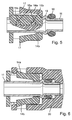
- Exemplary of a pressure line according to the invention is in the figure 2, the pressure line 11, which connects the two components slave cylinder 5 and pressure relief valve 2 together and shown in Figure 3 whose cross section.
- FIG. 5 again shows the components to be connected shown in FIG. 4 in a sectional view. From this figure, the connection of the two cylindrical shells 14a and 14b is clearly visible.
- FIG. 6 the connector 14 connected to the pressure line 11 is plugged into a connection component 20. From this representation, the function of the snap elements 17 in the connection component 20 can be seen. These snap when assembling the end of the pressure line 11 with the connection component 20 in a recess provided in this. Thus, a frictional connection between the end of the pressure line 11 and the connection member 20 is made, which, however, is reversible if necessary.
Abstract
Description
Die Erfindung betrifft eine Druckleitung zur Realisierung einer hydraulischen Übertragungsstrecke insbesondere in einem Kraftfahrzeug gemäß dem Oberbegriff des Anspruchs 1.The invention relates to a pressure line for realizing a hydraulic transmission path, in particular in a motor vehicle according to the preamble of claim 1.
In einem Kraftfahrzeug weist das Fluidsystem hydraulische Eigenschwingungen auf, die vom Verbrennungsmotor herrühren, und eine Summe von harmonischen Anregungen verschiedener Ordnung darstellen. Die Amplituden und Phasen dieser Schwingungen sind einerseits abhängig von der Drehzahl des Verbrennungsmotors und andererseits von den hydraulischen Eigenfrequenzen des Fluidsystems. Diese Eigenfrequenzen lassen sich u. a. aus der Länge der Druckleitung und der Schallgeschwindigkeit bestimmen. Wenn Erregerfrequenzen mit solchen hydraulischen Eigenfrequenzen zusammentreffen, gerät das fluidische System in Resonanz. Dabei können die Pulsationsamplituden so stark ansteigen, dass es im schlimmsten Fall zur Beeinträchtigung der hydraulischen Übertragung kommt, zumindest jedoch zu störenden Geräuschabstrahlungen in den Fahrzeuginnenraum.In a motor vehicle, the fluid system has hydraulic natural oscillations that originate from the internal combustion engine and represent a sum of harmonic excitations of different order. The amplitudes and phases of these oscillations are dependent on the one hand on the speed of the internal combustion engine and on the other hand on the hydraulic natural frequencies of the fluid system. These natural frequencies can u. a. determine from the length of the pressure line and the speed of sound. When excitation frequencies coincide with such natural hydraulic frequencies, the fluidic system resonates. In this case, the pulsation amplitudes can rise so much that in the worst case, the hydraulic transmission is impaired, but at least disturbing noise emissions into the vehicle interior.
Die Luftschwingungen, die das menschliche Ohr wahrnimmt, werden dabei nicht nur von den Elementen im hydraulischen System abgestrahlt, in denen sich die Schwingungsquelle befindet, sondern häufig zu einem viel größeren Teil von anderen Elementen, zu denen die Schwingungen über feste Werkstoffbrücken weitergeleitet werden. Eine dieser Brücken stellt die Druckleitung dar. Mit Hilfe der geometrischen Auslegung der Druckleitung ist deren Eigenfrequenz und somit der Übertragungsweg beeinflussbar. Die geometrische Auslegung der Druckleitung ist jedoch auch von dem zur Verfügung stehenden Bauraum im Fahrzeug abhängig. Aus diesem Grunde ist es nur in den seltensten Fällen möglich, eine Druckleitung gerade zu verlegen. Meist sind unterschiedlichste Formen von Krümmungen in der Druckleitung notwendig, um die entsprechenden Bauteile miteinander zu verbinden.The air vibrations that the human ear perceives are radiated not only by the elements in the hydraulic system in which the vibration source is located, but often to a much greater extent by other elements, to which the vibrations are transmitted via solid material bridges. One of these bridges represents the pressure line. With the help of the geometric design of the pressure line whose natural frequency and thus the transmission path can be influenced. However, the geometric design of the pressure line is also dependent on the available space in the vehicle. For this reason, it is only possible in the rarest cases, straight to lay a pressure line. Most different forms of curvatures in the pressure line are necessary to connect the corresponding components together.
Nach der VDI- Richtlinie 3842 "Schwingungen in Rohleitungssystemen" sind die Eigenfrequenzgleichungen verschiedener Schwingungsarten dargestellt. Die Formel zur Berechnung der Eigenfrequenzen f0j für freie, ungedämpfte Balkenschwingungen lautet: 
λ j - abhängig von den Randbedingungen
Fall: gelenkig- gelenkig => λ j = jπ wobei j = 1, 2, 3,.....
I - Leitungslänge [m]
E - Elastizitätsmodul [N/m2]
I - Trägheitsmoment [m4]
µ - Massenbelegung pro Längeneinheit [kg/m]
µ = pA 


λ j - depending on the boundary conditions
Case: articulated => λ j = jπ where j = 1, 2, 3, .....
I - cable length [m]
E elastic modulus [N / m 2 ]
I - moment of inertia [m 4 ]
μ - mass assignment per unit length [kg / m]
μ = pA
Derzeit ist es allgemein üblich für in Kraftfahrzeuge eingesetzte Druckleitungen Rohre aus Kunststoff, wie PA 12, zu verwenden, die einen Innendurchmesser von 4 bis 4,5 mm und Wandstärken von 2 bis 2,5 mm aufweisen. Wie bereits erwähnt, ist aus diesen Werten die Eigenfrequenz der Druckleitung ableitbar, die sich aus der Wandstärke, also der Differenz von deren Außendurchmesser zu deren Innendurchmesser ergibt, der Länge und der Dichte des verwendeten Werkstoffes. Bei Leitungen, die gleiche (konstante) Länge, gleichen Werkstoff und gleiche Randbedingungen haben, bleiben als auf die Eigenfrequenz einer Druckleitung Einfluss ausübende Faktoren, nur noch die Größe für deren Außen- und Innendurchmesser übrig.At present, it is common practice to use plastic pipes used in automotive vehicles, such as
Sollen, gleiche Längen vorausgesetzt, die derzeit am Markt eingesetzten Druckleitungen hinsichtlich ihrer Außen- und Innendurchmesser miteinander verglichen werden, ist es sinnvoll, zuvor einen Vergleichsfaktor k = (D2 + d2) einzuführen, der gleichzeitig auch ein Indiz für die Steifigkeit der aus gleichem Werkstoff hergestellten Druckleitungen darstellt.
Aus der aufgeführten Tabelle ist ersichtlich, dass der Wert des Faktors k um die 80 mm2 schwankt. Das bedeutet, dass diese so dimensionierten aus gleichem Werkstoff bestehenden Druckleitungen eine hohe Steifigkeit aufweisen. Diese hohe Steifigkeit ist jedoch bei der Herstellung von Krümmungen in Druckleitungen selbst hinderlich. Die bereits vorgeformten Druckleitungen lassen darüber hinaus keine flexible Verlegung im Fahrzeuginnenraum zu. Die Krümmungen vor der Verlegung im Fahrzeug werden zurzeit so in die Leitung eingebracht, indem die Leitung auf eine bestimmte Temperatur vorgewärmt und in eine der künftigen Form entsprechende Biegeeinrichtung eingelegt wird. Dieses Einlegen der Leitung in die Form erfordert einen erheblichen Kraftaufwand. Dabei ist zu beachten, dass der Biegeradius an den jeweiligen Außendurchmesser der Leitung gekoppelt ist, wodurch bei entsprechend großem Außendurchmesser auch der Biegeradius groß sein muss.From the listed table it can be seen that the value of the factor k varies by 80 mm 2 . This means that these so dimensioned from the same material existing pressure lines have a high rigidity. However, this high rigidity is a hindrance in the production of bends in pressure lines themselves. In addition, the already preformed pressure lines do not permit flexible laying in the vehicle interior. The curvatures prior to installation in the vehicle are currently being introduced into the conduit by preheating the conduit to a predetermined temperature and placing it in a bending device corresponding to the future shape. This insertion of the line into the mold requires considerable effort. It should be noted that the bending radius is coupled to the respective outer diameter of the line, whereby with a correspondingly large outer diameter and the bending radius must be large.
Weiterhin weisen die Druckleitungen endseitig Konnektoren auf, um mit anderen Bauteilen verbunden werden zu können. Dazu werden entweder die Leitungsendungen mit Gewinde versehen, wobei der aus Stahl bestehende Konnektor ebenfalls mit Gewinde versehen ist, um auf die Leitungsenden aufgeschraubt werden zu können. Eine andere Möglichkeit besteht darin, die Konnektoren mit den Leitungsenden zu verkrimpen oder mit diesen zu verlöten. Diese Techniken sind jedoch sehr aufwändig und benötigen einen erheblichen Zeitaufwand.Furthermore, the pressure lines end connectors on to be connected to other components can. For this purpose, either the line endings are provided with thread, wherein the existing steel connector is also threaded in order to be screwed onto the line ends can. Another possibility is to crimp or solder the connectors to the lead ends. However, these techniques are very complex and require a considerable amount of time.
Deshalb ist es Aufgabe der Erfindung, eine Druckleitung herzustellen, mit der einerseits die Eigenfrequenz zu kleineren Werten verschoben wird, um die Geräuschübertragung in den Fahrgastinnenraum zu reduzieren, und die andererseits eine Steifigkeit aufweist, die eine Formbarkeit ohne zusätzliche Hilfsmittel erlaubt und eine flexible Verlegung im Fahrzeug zulässt.It is therefore an object of the invention to produce a pressure line, with the one hand, the natural frequency is shifted to smaller values in order to reduce the noise transmission in the passenger compartment, and on the other hand, has a stiffness, the one Moldability allowed without additional aids and allows flexible installation in the vehicle.
Weiterhin ist es Aufgabe der Erfindung, die Kosten für die Herstellung und Montage der Konnektoren an den Druckleitungsenden zu reduzieren.Furthermore, it is an object of the invention to reduce the cost of manufacturing and assembly of the connectors to the pressure line ends.
Diese Aufgabe wird mit den Merkmalen des Anspruchs 1 gelöst, indem ein Vergleichswert "k" des Kunststoffrohres, der definiert ist als k = (D2 + d2), kleiner als 70 mm2 ist.This object is achieved with the features of claim 1 by a comparison value "k" of the plastic pipe, which is defined as k = (D 2 + d 2 ), is less than 70 mm 2 .
Mit Hilfe einer solchen konstruktiven Auslegung des Rohres wird eine hohe Flexibilität erzielt, die eine Verlegung in sehr engen Bauräumen möglich macht. Somit können glatte, unvorgebogene Rohre, das heißt unkonfektionierte Ware "von der Stange" zur beliebigen Verlegung zum Einsatz kommen. Bei der Wahl einer geringen Wandstärke ist es möglich, ohne Vornahme eines vorgeschalteten Vorwärmprozesses, kleine Biegeradien innerhalb seiner zu realisieren.With the help of such a constructive design of the tube high flexibility is achieved, which makes a laying in very tight spaces possible. Thus, smooth, unvorgebogene pipes, that is, unassembled goods "off the rack" come to any laying used. When choosing a small wall thickness, it is possible, without making an upstream preheating, to realize small bending radii within it.
Eine besonders vorteilhafte Ausgestaltung der Erfindung sieht vor, dass die Druckleitung bzw. ein Teilabschnitt davon PA12 oder PA612 aufweist. Aufgrund der konstruktiven Gestaltung der Leitung, in dem vorzugsweise für den Innendurchmesser d = 3 mm und für den Außendurchmesser D = 5 mm gewählt werden, wird eine dünne Leitung erzielt, die aus kostengünstigem Werkstoff herstellbar ist und kleine Biegeradien zulässt Weiterhin bieten diese aus den genannten Kunststoffen hergestellten Leitungen mit dieser geringen Wandstärke, die zusätzlich noch entsprechend modifiziert wurden, die Möglichkeit, weniger Volumen aufzunehmen und höheren Betriebsdrücken sowie Betriebstemperaturen standzuhalten. Außerdem bietet diese dünne Leitung Vorteile hinsichtlich des Berstdruckes und der Steifigkeit gegenüber dem Stand der Technik.A particularly advantageous embodiment of the invention provides that the pressure line or a partial section thereof has PA12 or PA612. Due to the constructive design of the line, in which preferably for the inner diameter d = 3 mm and for the outer diameter D = 5 mm are selected, a thin line is achieved, which can be produced from inexpensive material and small bending radii allows Furthermore, these offer the above Plastics produced lines with this small wall thickness, which were additionally modified accordingly, the ability to absorb less volume and withstand higher operating pressures and operating temperatures. In addition, this thin line offers advantages in terms of bursting pressure and rigidity over the prior art.
Da der Außendurchmesser dieser Druckleitung in vorteilhafter Weise denen von Standardrohrleitungen, können die im Fahrzeug für die Befestigung der übrigen Leitungen vorgesehenen Befestigungselemente auch für die Befestigung der Druckleitung mit genutzt werden, wodurch wiederum Kosten eingespart werden können.Since the outer diameter of this pressure line advantageously those of standard pipelines, which are provided in the vehicle for the attachment of the other lines fasteners can also be used for the attachment of the pressure line, which in turn costs can be saved.
In weiterer vorteilhafter Ausgestaltung der Erfindung ist es sinnvoll, diese erfindungsgemäße Druckleitung sowohl zur Verbindung von Betätigungselementen für Kupplungen als auch zur Verbindung der Betätigungselemente für Bremsen einzusetzen. Somit sind für beide hydraulischen Systeme die gleichen Leitungen einsetzbar, wodurch eine erhebliche Kosteneinsparung möglich ist.In a further advantageous embodiment of the invention, it is useful to use this pressure line according to the invention both for connecting actuators for clutches and for connecting the actuators for brakes. Thus, for both hydraulic Systems can be used the same lines, whereby a significant cost savings is possible.
Weiterhin wird die Aufgabe der Erfindung mit den Merkmalen des Anspruchs 6 gelöst. Somit bestehen die Konnektoren aus zwei miteinander verbindbaren Zylinderschalen.Furthermore, the object of the invention with the features of
In vorteilhafter Ausgestaltung der Erfindung sind die Zylinderschalen jeweils mit Rastelementen versehen, wobei an jeder Zylinderschale beidseitig zur Zylinderachse die Rastelemente invers oder jeweils gleich ausgeführt werden.In an advantageous embodiment of the invention, the cylinder shells are each provided with locking elements, wherein on each cylinder shell on both sides of the cylinder axis, the locking elements are inversely or in each case performed the same.
Vorteilhaft ist weiterhin, dass am Umfang mindestens einer Zylinderschale ein Schnappelement vorgesehen ist, das elastisch aufweitbar ist.A further advantage is that on the circumference of at least one cylinder shell a snap element is provided, which is elastically expandable.
Je nach Größe des Konnektors können am Umfang beider Zylinderschalen jeweils mindestens ein Schnappelement vorgesehen sein.Depending on the size of the connector, at least one snap element may be provided on the circumference of both cylindrical shells.
In vorteilhafter Ausgestaltung der Erfindung ist der Konnektor aus einem Kunststoffmaterial hergestellt.In an advantageous embodiment of the invention, the connector is made of a plastic material.
In vorteilhafter Ausgestaltung sind die Zylinderschalen zur Korrespondenz mit einem an einem Leitungsende vorgesehenen Anschlag jeweils mit einer der Form dieses Anschlags entsprechenden Nut versehen.In an advantageous embodiment, the cylindrical shells are provided for correspondence with a provided on a line end stop each with a shape corresponding to the stop groove.
Die Erfindung soll nachfolgend anhand eines Ausführungsbeispiels näher erläutert werden.The invention will be explained in more detail with reference to an embodiment.
Es zeigen:
- Figur 1
- einen schematischen Überblick eines hydraulische Systems zur Betätigung einer Reibungskupplung
Figur 2- die Verbindung zwischen Druckbegrenzungsventil und Nehmerzylinder mittels erfindungsgemäßer Druckleitung
Figur 3- einen Querschnitt der Druckleitung
Figur 4- eine räumliche Darstellung des mit einem Konnektor zu versehenden Endbereiches einer Druckleitung
Figur 5- eine Schnittdarstellung der Bauteile, gemäß
Figur 4, Figur 6- eine mit einem Anschlussbauteil mittels Konnektor verbundene Druckleitung.
- FIG. 1
- a schematic overview of a hydraulic system for actuating a friction clutch
- FIG. 2
- the connection between the pressure relief valve and slave cylinder by means of inventive pressure line
- FIG. 3
- a cross section of the pressure line
- FIG. 4
- a spatial representation of the end to be provided with a connector of a pressure line
- FIG. 5
- a sectional view of the components, according to Figure 4,
- FIG. 6
- a pressure line connected to a connection component by means of a connector.
Fig. 1 zeigt in schematischer Darstellung eine mögliche Ausgestaltung eines hydraulischen Systems 1 anhand einer Kupplungsausrückvorrichtung 3 mit einem Geberzylinder 4 und einem Nehmerzylinder 5. In die Nehmerzylinder 5 und Geberzylinder 4 verbindenden Druckleitungen 11, 12 ist optional ein Druckbegrenzungsventil 2 eingebaut.Fig. 1 shows a schematic representation of a possible embodiment of a hydraulic system 1 based on a
Die Kupplungsausrückvorrichtung 3 betätigt die Kupplung 7 hydraulisch durch Beaufschlagung des Geberzylinders 4 mittels eines Betätigungsgliedes 14, das ein Fußpedal, ein Aktor, beispielsweise ein elektrischer Aktor, oder dergleichen sein kann.The
Mittels einer mechanischen Übertragung 13 wird Druck im Geberzylinder 4 aufgebaut, der über den Leitungsstrang 12, über das Druckbegrenzungsventil 2 und den Leistungsstrang 11 einen Druck im Nehmerzylinder 5 aufbaut. Der Nehmerzylinder 5 kann, wie im gezeigten Beispiel, parallel zur Getriebeeingangswelle 10 angeordnet sein und über eine Ausrückmechanik 6 auf die Tellerfeder der Kupplung 7 zu deren axialer Verlagerung einwirken. Zum Aufbringen der Ausrückkraft ist der Nehmerzylinder 5 jeweils gehäusefest am Getriebegehäuse, das hier nicht näher dargestellt ist, oder an einem anderen gehäusefesten Bauteil angebracht. Die Getriebeeingangswelle 10 überträgt bei geschlossener Kupplung 7 das Drehmoment der Brennkraftmaschine 8 über die Kurbelwelle 9 auf ein nicht näher dargestelltes Getriebe und anschließend auf die Antriebsräder eines Kraftfahrzeuges.By means of a
Beispielhaft für eine erfindungsgemäße Druckleitung ist in der Figur 2 die Druckleitung 11, die die beiden Bauteile Nehmerzylinder 5 und Druckbegrenzungsventil 2 miteinander verbindet und in Figur 3 deren Querschnitt dargestellt.Exemplary of a pressure line according to the invention is in the figure 2, the
Aus der Figur 4 sind durch die perspektivische Darstellung des Konnektors 14 mit seinen beiden Halbschalen 14a und 14b, die durch die Rastelemente 15a und 15b definierten Verbindungsstellen deutlich aufgezeigt. Weiterhin ist die Leitung 11 erkennbar, die im Endbereich angestaucht wurde, um somit einen Anschlag 19 zu bilden. Dieser Anschlag 19 dient mit seiner rechten Stirnseite als Begrenzung des als O-Ring ausgebildeten Dichtringes 16 und mit seiner linken Stirnseite als Begrenzung für die beiden Zylinderschalen 14a und 14b auf der Druckleitung 11. Weiterhin sind an beiden Zylinderschalen 14a und 14b die aufweitbaren Schnappelemente 17 erkennbar. Diese Schnappelemente 17 haben in dieser Darstellung eine flächige Ausbildung. Ebenso gut könnten sie als Haken ausgebildet sein.From the figure 4 are clearly shown by the perspective view of the
In der Figur 5 sind nochmals die in der Figur 4 dargestellten zu verbindenden Bauteile in einer Schnittdarstellung aufgezeigt. Aus dieser Figur ist die Verbindung der beiden Zylinderschalen 14a und 14b deutlich sichtbar.FIG. 5 again shows the components to be connected shown in FIG. 4 in a sectional view. From this figure, the connection of the two
In einer weiteren Darstellung, der Figur 6, ist der mit der Druckleitung 11 verbundene Konnektor 14 in ein Anschlussbauteil 20 eingesteckt. Aus dieser Darstellung ist die Funktion der Schnappelemente 17 im Anschlussbauteil 20 erkennbar. Diese rasten beim Zusammenfügen des Endes der Druckleitung 11 mit den Anschlussbauteil 20 in eine in diesem vorgesehene Aussparung ein. Somit wird eine kraftschlüssige Verbindung zwischen dem Ende der Druckleitung 11 und dem Anschlussbauteil 20 hergestellt, die jedoch im Bedarfsfall reversibel ist.In a further illustration, FIG. 6, the
- 11
- Hydraulisches SystemHydraulic system
- 22
- DruckbegrenzungsventilPressure relief valve
- 33
- KupplungsausrückvorrichtungClutch bearing
- 44
- GeberzylinderMaster cylinder
- 55
- Nehmerzylinderslave cylinder
- 66
- Ausrückmechanikdisengaging mechanism
- 77
- Kupplungclutch
- 88th
- BrennkraftmaschineInternal combustion engine
- 99
- Kurbelwellecrankshaft
- 1010
- GetriebeeingangswelleTransmission input shaft
- 1111
- Teilabschnitt eines Kunststoffrohres / DruckleitungPart of a plastic pipe / pressure line
- 1212
- Teilabschnitt eines Kunststoffrohres / DruckleitungPart of a plastic pipe / pressure line
- 1313
- mechanische Übertragungmechanical transmission
- 1414
- Leitungsanschluss / KonnektorCable connection / connector
- DD
- Außendurchmesser der DruckleitungOuter diameter of the pressure line
- dd
- Innendurchmesser der DruckleitungInner diameter of the pressure line
- 14a14a
- Zylinderschalecylindrical shell
- 14b14b
- Zylinderschalecylindrical shell
- 15a15a
- Rastelementlocking element
- 15b15b
- Rastelementlocking element
- 1616
- Dichtring / O-RingSealing ring / O-ring
- 1717
- Schnappelementsnap element
- 1818
- Zylinderachsecylinder axis
- 1919
- Anschlagattack
- 2020
- Aufnahme- / AnschlussbauteilReceiving / connection component
Claims (16)
Applications Claiming Priority (1)
| Application Number | Priority Date | Filing Date | Title |
|---|---|---|---|
| DE102005042976 | 2005-09-09 |
Publications (2)
| Publication Number | Publication Date |
|---|---|
| EP1762767A2 true EP1762767A2 (en) | 2007-03-14 |
| EP1762767A3 EP1762767A3 (en) | 2008-01-16 |
Family
ID=37507591
Family Applications (1)
| Application Number | Title | Priority Date | Filing Date |
|---|---|---|---|
| EP06018187A Ceased EP1762767A3 (en) | 2005-09-09 | 2006-08-31 | Pressure line |
Country Status (2)
| Country | Link |
|---|---|
| EP (1) | EP1762767A3 (en) |
| BR (1) | BRPI0603773A (en) |
Cited By (2)
| Publication number | Priority date | Publication date | Assignee | Title |
|---|---|---|---|---|
| WO2009021480A1 (en) * | 2007-08-16 | 2009-02-19 | Luk Lamellen Und Kupplungsbau Beteiligungs Kg | Clutch release system |
| FR3027636A1 (en) * | 2014-10-22 | 2016-04-29 | Peugeot Citroen Automobiles Sa | PIPE FOR HYDRAULIC CLUTCH CONTROL COMPRISING A PLASTIC PIPE AND A FLEXIBLE PIPE |
Families Citing this family (1)
| Publication number | Priority date | Publication date | Assignee | Title |
|---|---|---|---|---|
| CN101649931B (en) * | 2009-09-08 | 2011-03-23 | 新兴铸管股份有限公司 | Modular cast iron tube of self-anchoring joint |
Citations (2)
| Publication number | Priority date | Publication date | Assignee | Title |
|---|---|---|---|---|
| US20030012909A1 (en) | 2000-03-10 | 2003-01-16 | Stephane Jung | Double-layer pipe |
| DE10134884A1 (en) | 2001-07-18 | 2003-02-06 | Zf Sachs Ag | Connection line for a hydraulic system |
Family Cites Families (2)
| Publication number | Priority date | Publication date | Assignee | Title |
|---|---|---|---|---|
| US6040025A (en) * | 1994-04-28 | 2000-03-21 | Elf Atochem S.A. | Adhesion binder containing glutarimide moieties |
| EP1306203A1 (en) * | 2001-10-26 | 2003-05-02 | Atofina | Polyamide or polyester- and aluminium-based multilayer tube |
-
2006
- 2006-08-31 EP EP06018187A patent/EP1762767A3/en not_active Ceased
- 2006-09-08 BR BRPI0603773 patent/BRPI0603773A/en not_active Application Discontinuation
Patent Citations (2)
| Publication number | Priority date | Publication date | Assignee | Title |
|---|---|---|---|---|
| US20030012909A1 (en) | 2000-03-10 | 2003-01-16 | Stephane Jung | Double-layer pipe |
| DE10134884A1 (en) | 2001-07-18 | 2003-02-06 | Zf Sachs Ag | Connection line for a hydraulic system |
Cited By (2)
| Publication number | Priority date | Publication date | Assignee | Title |
|---|---|---|---|---|
| WO2009021480A1 (en) * | 2007-08-16 | 2009-02-19 | Luk Lamellen Und Kupplungsbau Beteiligungs Kg | Clutch release system |
| FR3027636A1 (en) * | 2014-10-22 | 2016-04-29 | Peugeot Citroen Automobiles Sa | PIPE FOR HYDRAULIC CLUTCH CONTROL COMPRISING A PLASTIC PIPE AND A FLEXIBLE PIPE |
Also Published As
| Publication number | Publication date |
|---|---|
| BRPI0603773A (en) | 2007-04-27 |
| EP1762767A3 (en) | 2008-01-16 |
Similar Documents
| Publication | Publication Date | Title |
|---|---|---|
| DE102006040994A1 (en) | Pressure pipe for hydraulic system, has end-sided apposite connectors and reference value of plastic pipe, which is sum of square of outer diameter and square of inner diameter, is less than seventy square mm | |
| EP0152753B1 (en) | Flange connection for fibre-reinforced plastic pipe sections | |
| DE60316979T2 (en) | TUBE WITH A MULTIPLE METAL WIRE OR TUBE | |
| DE3604672A1 (en) | ELEMENT FOR SEALING JOURNALS | |
| EP1762767A2 (en) | Pressure line | |
| DE102014207487A1 (en) | Modular system for an evaporator device | |
| DE102005015483A1 (en) | Interconnecting feeder line for power unit of motor vehicle, comprises of fluid lines and conductors wrapped in plastic coating and embedded in a section of feeder line | |
| DE102011018275A1 (en) | Piping system for supplying fluid i.e. oil, that is used for e.g. cooling, of supercharger of combustion engine in motor car, has compensator compensating loads due to vibration, expansion and/or compression during operation of car | |
| DE69721720T2 (en) | Flexible corrugated pipe for decoupling exhaust pipe in a motor vehicle | |
| EP0668179B1 (en) | Preassembled fluid piping, adapted to the mounting into a motor vehicle on an automatised assembly line | |
| DE102010002925A1 (en) | Brake booster | |
| DE602005000459T2 (en) | Arrangement for connecting a rigid pipe to a flexible hose | |
| EP0925984B1 (en) | Exhaust system for a motor vehicle, as well as motor vehicle with an exhaust system | |
| DE19951947A1 (en) | Hydraulic pressure system for operation of clutch or brake systems on road vehicle has flexible corrugated hose between cylinder connected to pedal and cylinder connected to clutch or brake | |
| DE102013207072A1 (en) | Connection unit i.e. anti-swivelling connection unit, for fastening of e.g. hydraulic fluid propelled high pressure line to component in coupling system of motor car, has housing parts whose aperture axially extends by housing parts | |
| DE10242627A1 (en) | Arrangement for fastening of pipe or hose to bumper of motor vehicle has at least two bendable flexible plates extending at right angles to one another, and one flexible plate with a C-form or hook-form construction | |
| DE102018117090A1 (en) | Pedal force simulator and assembly method of a pedal force simulator | |
| WO2007017103A1 (en) | Refrigerant line | |
| DE102004037994A1 (en) | Notch plate and connecting rod joint, has connecting rod with crimp fold at end that faces notch plate before mounting, and another fold provided in axial direction behind former fold at preset distance | |
| EP1615789B1 (en) | Motor vehicle comprising an air conditioning system | |
| DE102018214675B3 (en) | Method for producing a housing and motor vehicle | |
| DE19960650C1 (en) | Pipeline e.g. for braking system, hydraulic system or fuel supply system in automobile, provided with integral end fitting for coupling pipeline to hose | |
| DE3913356C2 (en) | ||
| EP2610117B1 (en) | Fastening system for a wiper drive of a motor vehicle | |
| DE60307229T2 (en) | DEVICE FOR TRANSMISSION OF LATHE |
Legal Events
| Date | Code | Title | Description |
|---|---|---|---|
| PUAI | Public reference made under article 153(3) epc to a published international application that has entered the european phase |
Free format text: ORIGINAL CODE: 0009012 |
|
| AK | Designated contracting states |
Kind code of ref document: A2 Designated state(s): AT BE BG CH CY CZ DE DK EE ES FI FR GB GR HU IE IS IT LI LT LU LV MC NL PL PT RO SE SI SK TR |
|
| AX | Request for extension of the european patent |
Extension state: AL BA HR MK YU |
|
| PUAL | Search report despatched |
Free format text: ORIGINAL CODE: 0009013 |
|
| AK | Designated contracting states |
Kind code of ref document: A3 Designated state(s): AT BE BG CH CY CZ DE DK EE ES FI FR GB GR HU IE IS IT LI LT LU LV MC NL PL PT RO SE SI SK TR |
|
| AX | Request for extension of the european patent |
Extension state: AL BA HR MK YU |
|
| 17P | Request for examination filed |
Effective date: 20080716 |
|
| 17Q | First examination report despatched |
Effective date: 20080815 |
|
| AKX | Designation fees paid |
Designated state(s): AT BE BG CH CY CZ DE DK EE ES FI FR GB GR HU IE IS IT LI LT LU LV MC NL PL PT RO SE SI SK TR |
|
| RAP1 | Party data changed (applicant data changed or rights of an application transferred) |
Owner name: SCHAEFFLER TECHNOLOGIES GMBH & CO. KG |
|
| RAP1 | Party data changed (applicant data changed or rights of an application transferred) |
Owner name: SCHAEFFLER TECHNOLOGIES AG & CO. KG |
|
| STAA | Information on the status of an ep patent application or granted ep patent |
Free format text: STATUS: THE APPLICATION HAS BEEN REFUSED |
|
| 18R | Application refused |
Effective date: 20130310 |
|
| P01 | Opt-out of the competence of the unified patent court (upc) registered |
Effective date: 20230524 |