EP1762723A1 - Injection valve and method of making orifice - Google Patents
Injection valve and method of making orifice Download PDFInfo
- Publication number
- EP1762723A1 EP1762723A1 EP06019201A EP06019201A EP1762723A1 EP 1762723 A1 EP1762723 A1 EP 1762723A1 EP 06019201 A EP06019201 A EP 06019201A EP 06019201 A EP06019201 A EP 06019201A EP 1762723 A1 EP1762723 A1 EP 1762723A1
- Authority
- EP
- European Patent Office
- Prior art keywords
- orifice
- surface portion
- flat surface
- making
- injection valve
- Prior art date
- Legal status (The legal status is an assumption and is not a legal conclusion. Google has not performed a legal analysis and makes no representation as to the accuracy of the status listed.)
- Granted
Links
- 238000002347 injection Methods 0.000 title claims abstract description 42
- 239000007924 injection Substances 0.000 title claims abstract description 42
- 238000004519 manufacturing process Methods 0.000 title claims description 7
- 239000012530 fluid Substances 0.000 claims abstract description 9
- 238000003754 machining Methods 0.000 claims description 9
- 238000000034 method Methods 0.000 claims description 7
- 238000005520 cutting process Methods 0.000 claims description 6
- OKTJSMMVPCPJKN-UHFFFAOYSA-N Carbon Chemical compound [C] OKTJSMMVPCPJKN-UHFFFAOYSA-N 0.000 claims description 3
- 229910052799 carbon Inorganic materials 0.000 claims description 3
- 229910000734 martensite Inorganic materials 0.000 claims description 3
- 229910001220 stainless steel Inorganic materials 0.000 claims description 3
- 239000010935 stainless steel Substances 0.000 claims description 3
- 238000011144 upstream manufacturing Methods 0.000 claims description 3
- 239000000446 fuel Substances 0.000 description 11
- 239000007921 spray Substances 0.000 description 7
- 238000003825 pressing Methods 0.000 description 3
- 238000003672 processing method Methods 0.000 description 3
- 230000035515 penetration Effects 0.000 description 2
- 238000005452 bending Methods 0.000 description 1
- 238000011109 contamination Methods 0.000 description 1
- 230000003247 decreasing effect Effects 0.000 description 1
- 238000005553 drilling Methods 0.000 description 1
- -1 e.g. Substances 0.000 description 1
- 238000005242 forging Methods 0.000 description 1
- 239000003973 paint Substances 0.000 description 1
- 230000002093 peripheral effect Effects 0.000 description 1
- 230000001105 regulatory effect Effects 0.000 description 1
- 230000003746 surface roughness Effects 0.000 description 1
- XLYOFNOQVPJJNP-UHFFFAOYSA-N water Substances O XLYOFNOQVPJJNP-UHFFFAOYSA-N 0.000 description 1
Images


Classifications
-
- B—PERFORMING OPERATIONS; TRANSPORTING
- B21—MECHANICAL METAL-WORKING WITHOUT ESSENTIALLY REMOVING MATERIAL; PUNCHING METAL
- B21J—FORGING; HAMMERING; PRESSING METAL; RIVETING; FORGE FURNACES
- B21J5/00—Methods for forging, hammering, or pressing; Special equipment or accessories therefor
- B21J5/06—Methods for forging, hammering, or pressing; Special equipment or accessories therefor for performing particular operations
- B21J5/10—Piercing billets
-
- B—PERFORMING OPERATIONS; TRANSPORTING
- B21—MECHANICAL METAL-WORKING WITHOUT ESSENTIALLY REMOVING MATERIAL; PUNCHING METAL
- B21J—FORGING; HAMMERING; PRESSING METAL; RIVETING; FORGE FURNACES
- B21J9/00—Forging presses
- B21J9/02—Special design or construction
- B21J9/04—Piercing presses
-
- F—MECHANICAL ENGINEERING; LIGHTING; HEATING; WEAPONS; BLASTING
- F02—COMBUSTION ENGINES; HOT-GAS OR COMBUSTION-PRODUCT ENGINE PLANTS
- F02M—SUPPLYING COMBUSTION ENGINES IN GENERAL WITH COMBUSTIBLE MIXTURES OR CONSTITUENTS THEREOF
- F02M61/00—Fuel-injectors not provided for in groups F02M39/00 - F02M57/00 or F02M67/00
- F02M61/16—Details not provided for in, or of interest apart from, the apparatus of groups F02M61/02 - F02M61/14
- F02M61/162—Means to impart a whirling motion to fuel upstream or near discharging orifices
-
- F—MECHANICAL ENGINEERING; LIGHTING; HEATING; WEAPONS; BLASTING
- F02—COMBUSTION ENGINES; HOT-GAS OR COMBUSTION-PRODUCT ENGINE PLANTS
- F02M—SUPPLYING COMBUSTION ENGINES IN GENERAL WITH COMBUSTIBLE MIXTURES OR CONSTITUENTS THEREOF
- F02M61/00—Fuel-injectors not provided for in groups F02M39/00 - F02M57/00 or F02M67/00
- F02M61/16—Details not provided for in, or of interest apart from, the apparatus of groups F02M61/02 - F02M61/14
- F02M61/168—Assembling; Disassembling; Manufacturing; Adjusting
-
- F—MECHANICAL ENGINEERING; LIGHTING; HEATING; WEAPONS; BLASTING
- F02—COMBUSTION ENGINES; HOT-GAS OR COMBUSTION-PRODUCT ENGINE PLANTS
- F02M—SUPPLYING COMBUSTION ENGINES IN GENERAL WITH COMBUSTIBLE MIXTURES OR CONSTITUENTS THEREOF
- F02M61/00—Fuel-injectors not provided for in groups F02M39/00 - F02M57/00 or F02M67/00
- F02M61/16—Details not provided for in, or of interest apart from, the apparatus of groups F02M61/02 - F02M61/14
- F02M61/18—Injection nozzles, e.g. having valve seats; Details of valve member seated ends, not otherwise provided for
- F02M61/1853—Orifice plates
-
- F—MECHANICAL ENGINEERING; LIGHTING; HEATING; WEAPONS; BLASTING
- F02—COMBUSTION ENGINES; HOT-GAS OR COMBUSTION-PRODUCT ENGINE PLANTS
- F02M—SUPPLYING COMBUSTION ENGINES IN GENERAL WITH COMBUSTIBLE MIXTURES OR CONSTITUENTS THEREOF
- F02M61/00—Fuel-injectors not provided for in groups F02M39/00 - F02M57/00 or F02M67/00
- F02M61/04—Fuel-injectors not provided for in groups F02M39/00 - F02M57/00 or F02M67/00 having valves, e.g. having a plurality of valves in series
- F02M61/10—Other injectors with elongated valve bodies, i.e. of needle-valve type
- F02M61/12—Other injectors with elongated valve bodies, i.e. of needle-valve type characterised by the provision of guiding or centring means for valve bodies
-
- Y—GENERAL TAGGING OF NEW TECHNOLOGICAL DEVELOPMENTS; GENERAL TAGGING OF CROSS-SECTIONAL TECHNOLOGIES SPANNING OVER SEVERAL SECTIONS OF THE IPC; TECHNICAL SUBJECTS COVERED BY FORMER USPC CROSS-REFERENCE ART COLLECTIONS [XRACs] AND DIGESTS
- Y10—TECHNICAL SUBJECTS COVERED BY FORMER USPC
- Y10T—TECHNICAL SUBJECTS COVERED BY FORMER US CLASSIFICATION
- Y10T29/00—Metal working
- Y10T29/49—Method of mechanical manufacture
- Y10T29/49229—Prime mover or fluid pump making
- Y10T29/49298—Poppet or I.C. engine valve or valve seat making
Definitions
- the present invention relates to an injection valve for injecting a fluid, and more particularly, to an orifice for determining a flow rate, an orifice making method and an injection valve using the orifice.
- injection hole In fuel injection valves, conventional art where an orifice (injection hole) is provided in spherical projection by press working is disclosed in Japanese Patent Laid-Open No. Hei 7-63140 .
- the injection hole is formed by making an injection hole in a flat plate by press working or the like and by drawing a peripheral portion of the injection hole in a dome shape.
- Japanese Patent Laid-Open No. Hei 7-63140 is perforation by injection hole press working or drilling and by drawing around the hole. According to such a hole processing, as the injection hole is tapered, it is difficult to obtain a cylindrical orifice. Further, upon drawing, as the orifice is taper-deformed, the injection hole precision upon perforation cannot be maintained without difficulty. Accordingly, it is extremely difficult to obtain a ⁇ m-order precision injection hole.
- the present invention has an object to provide an injection valve where a flat surface portion vertical to the axis of an orifice is provided in a spherical projection on the downstream side of the orifice, and the orifice is formed in the flat surface portion, thereby homogeneity of spray is improved. Further, the invention has another object to provide a method for easily processing an orifice deflected in one or more directions.
- One representative injection valve according to the present invention may comprise:
- one representative orifice making method according to the present invention may comprise:
- an injection valve with improved spray homogeneity can be provided.
- the above features may be combined in any way either partly or as a whole.
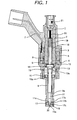
- Fig. 1 is a longitudinal sectional view showing the entire structure of an injection valve according to an embodiment of the present invention.
- An injection valve 1 has a magnetic circuit including a stationary core 2, a yoke 3, a housing 4 and a movable element 5, a coil 6 for exciting the magnetic circuit, and a terminal bobbin 7 to energize the coil 6.
- a seal ring 8 is interposed between the core 2 and the housing 4 so as to prevent inflow of fluid such as fuel into the coil 6.
- Valve parts are positioned in the housing 4.
- the movable element 5, a nozzle body 9 and a ring 10 for regulating a stroke of the movable element 5 are arranged.
- the movable element 5 is a combination of a valve needle 11 and a movable core 12 with a joint 13.
- a plate 14 for suppressing rebound of the movable element 5 at valve closing, in cooperation with a pipe 18, is provided between the movable core 12 and the joint 13.
- the housing 4 and the nozzle body 9 are joined to each other, and they construct an external cylindrical member for covering around the movable element 5.
- the nozzle body 9 is provided with an orifice plate 15 and a swirler 17.
- the orifice plate has a seat surface 15a (valve seat) and an orifice 32 at its end.
- the swirler 17 is to apply a swirling force for the fuel and to slidably guide the movable element 5 along with a guide plate 16.
- the nozzle body 9, the orifice plate 15 and the swirler 17 may be separate members, or may be integrated with each other.
- a spring 19 for exerting the valve needle 11 toward the seat surface 15a via the pipe 18 and the plate 14, an adjuster 20 for adjusting a pressing load on the spring 19, and a filter 21 for preventing extraneous contamination are provided inside the stationary core 2.
- the pressurized fuel first enters the nozzle body 9 via the core 2, the adjuster 20, the pipe 18 and a fuel passage 13a in the movable element 5.
- the fuel enters passages 17a and 17b of the swirler 17 from a fuel passage 16a of the guide plate 16 and a passage 9a of the nozzle body, and a swirling force is applied to the fuel by a swirl groove 17c of the swirler 17.
- the swirling-force applied fuel is injected through an orifice 32 from the gap between the needle head 11a and the seat surface 15a.
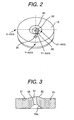
- Figs. 2 and 3 show a first embodiment of the present invention.
- Fig. 2 is a perspective view of the orifice plate 15.
- Fig. 3 is a longitudinal sectional view of Fig. 2 cut along a Y-axis.
- the orifice plate 15 has a spherical projection 30 to be a convex-curved surface at the center of its end surface.
- a flat surface portion 33 slanted toward a positioning hole 31 is a vertical surface to an axis of the orifice 32.
- the orifice 32 is slanted with respect to an axis of the fuel injection valve 1, and is opened vertically to the flat surface portion 33.
- the outlet side-end face of the orifice 32 is a flat end face.
- the seat surface 15a having an approximately conical shape is provided on the upstream side of the orifice 32.
- the injection timing of fluid becomes the same in the entire perimeter. Even in the case of an orifice deflected from the axis of an injection valve, the length of penetration can be uniformed, thus the homogeneity of spray can be improved.
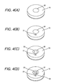
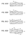
- Figs. 4 and 5 show processing steps of the orifice plate 15.
- Fig. 4 shows perspective views of the respective steps.
- Fig. 5 shows longitudinal sectional views.
- Fig. 4(I) and Fig. 5(I) show a blank having a spherical projection 30 at the center of an end surface of the orifice plate 15, formed by cutting or press working, or forging.
- Fig. 4(II) and Fig. 5(II) show the processed positioning hole 31 formed by press working or lathe turning, or cutting or electric discharge machining.
- Fig. 4(III) and Fig. 5(III) show the processed flat surface portion 33, processed to be an approximately vertical surface to the axis of the orifice 32.
- the processing is made by press working, lathe turning or cutting, or electric discharge machining.
- Fig. 4(IV) and Fig. 5(IV) show the processed orifice 32.
- an inner surface thereof can be formed in a full shear plane by pouch-shape processing, and the surface roughness can be greatly improved.
- an extruded portion 15b occurred at press working is cut upon processing of the seat surface 15a (valve seat).
- the seat surface 15a valve seat
- it may be arranged such that the seat surface 15a is processed in a blank state in advance then the orifice 32 is processed.
- Fig. 6 shows the press working as an example of processing method for the orifice plate.
- Fig. 6(I) shows a step of processing of the positioning hole 31.
- the orifice plate 15 is placed on the upper surface of a die 41, and its outer diameter is firmly held with a collet chuck 42.
- the positioning hole 31 is processed by pressing with a positioning hole processing unit 40a of a punch 40 while the orifice plate 15 is held.
- the processing of the positioning hole 31 may be executed by coining processing.
- Fig. 6 (II) shows a step of processing of the flat surface portion 33.
- the flat surface portion 33 is processed by pressing the flat surface portion 33 with a punch 43 while the orifice plate 15 is held with a collet chuck 42.
- the processing of the flat surface portion may be executed by coining processing and surface hardening processing.
- Fig. 6(III) shows a step of processing of the orifice 32.
- a cutting blade 44a of a punch 44 is pressed at a right angle against the flat surface portion 33 thereby the orifice 32 is extruded in a pouch shape.
- the flat surface portion 33 and the orifice 32 can be processed with high positional precision with reference to the positioning hole 31. Further, positioning is not necessary.
- the processing of the orifice 32 may be executed by extruding, half blanking, or stamping.
- a deep hole having an aspect ratio of 2 or higher can be easily processed even in martensite stainless steel with carbon content of 0.25% or higher (for example, SUS420J2).
- martensite stainless steel with carbon content of 0.25% or higher it is more desirable that the quenched hardness is equal to or higher than HRC 52.
- the drill or electrode can be prevented from being positionally shifted due to slipping.
- the orifice can be easily processed with high precision.
- Fig. 7 shows an example where six orifices 54, 55, 56, 57, 58 and 59 as plural orifices are made in an orifice plate 50.
- the downstream side of the orifice plate 50 has a concave portion formed by an inner wall 52 and an inner bottom 53.
- a spherical projection 51 is formed in the area of an inner bottom 53.
- the respective orifices 54, 55 , 56, 57, and 58 are opened in different directions, and flat surface portions 54a, 55a, 56a, 57a, 58a and 59a around the respective orifices are formed at right angles to the axes of the respective orifices.
- the orifices 54, 55, 56, 57, 58 and 59 are made at right angles to the respective flat surface portions, and outlets of the respective orifices are opened in the respective flat surface portions.
- orifices having different injection directions can be easily processed with high precision, especially by press working, lathe turning, electric discharge machining or the like, by providing plural flat surface portions respectively at right angles to the axes of plural orifices in a spherical projection on the orifice downstream side.
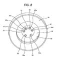
- Fig. 8 shows an example where six orifices 64, 65, 66, 67, 68 and 69 as plural orifices having different lengths from to each other are made in an orifice plate 60.
- the downstream side of the orifice plate 60 has a concave portion formed by an inner wall 62 and an inner bottom 63.
- a spherical projection 61 is formed in the area of an inner bottom surface 63.
- the respective orifices 64, 65, 66, 67, 68 and 69 are opened in different directions, and the outlets of the orifices are positioned in the respective hollows provided in the area of the spherical projection 61.
- the inner bottoms of the hollows are respectively formed with flat surface portions 64a, 65a, 66a, 67a, 68a and 69a.
- the flat surface portions 64a, 65a, 66a, 67a, 68a and 69a are formed at right angles to the axes of the respective orifices in the area of the spherical projection 61.
- the orifices 64, 65, 66, 67, 68 and 69 are made at right angles to the respective flat surface portions 64a, 65a, 66a, 67a, 68a and 69a, and the outlets of them are positioned in the respective flat surface portions.
- the depths of the flat surface portions 64a, 65a, 66a, 67a, 68a and 69a in the hollows are appropriately changed.
- the orifice lengths can be changed by providing hollow-flat surface portions at right angles to the axes of the orifices in the spherical projection on the orifice downstream side and by changing depths of the hollow- flat surface portions.
- the spray shape and processing characteristics can be improved.
- the outlet of the orifice is positioned in a surface at a right angle to the axis of the orifice, and fluid injection timing is the same in the entire perimeter. Even in an orifice deflected from the axis of an injection valve, the penetration length can be uniformed, and the homogeneity of spray is improved.
- the orifice length can be changed by providing a hollow-flat surface portion at a right angle to the axis of the orifice in the spherical projection on the orifice downstream side and changing the depth of the hollow-flat surface portion, thus spray shape can be optimized.
- the orifice can be easily processed with high precision especially by press working, lathe turning, electric discharge machining or the like, by providing a flat surface portion at a right angle to the axis of the orifice in the spherical projection on the orifice downstream side and by forming the orifice in the flat surface portion.
- orifices having different injection directions can be easily processed with high precision especially by press working, lathe turning, electric discharge machining or the like, by providing plural flat surface portions at right angles to the axes of the orifices in the spherical projection on the orifice downstream side.
- an orifice positioned with high precision can be processed with high productivity without positioning, by performing positioning and processing of a flat surface at right angle to the axis of the orifice and the orifice (especially, an orifice deflected from the axis of an injection valve or plural orifices) while a blank is chucked.
- the area where the flat surface portion 33 is formed is the spherical projection 30, however, the area may have other curved shape than the spherical surface (convex-curved surface portion).
- injection valve of the present invention is applicable to other fluid than the fuel, e.g., water, processing oil, oil paint, ink and gaseous matter.
- fluid e.g., water, processing oil, oil paint, ink and gaseous matter.
Landscapes
- Engineering & Computer Science (AREA)
- Mechanical Engineering (AREA)
- Chemical & Material Sciences (AREA)
- Combustion & Propulsion (AREA)
- General Engineering & Computer Science (AREA)
- Manufacturing & Machinery (AREA)
- Fuel-Injection Apparatus (AREA)
Abstract
Description
- The present invention relates to an injection valve for injecting a fluid, and more particularly, to an orifice for determining a flow rate, an orifice making method and an injection valve using the orifice.
- In fuel injection valves, conventional art where an orifice (injection hole) is provided in spherical projection by press working is disclosed in
Japanese Patent Laid-Open No. Hei 7-63140 - Further, as an processing method of deflected orifice in nozzle body manufacturing, press working disclosed in
Japanese Patent Laid-Open No. 2001-96196 - However, the prior art disclosed in
Japanese Patent Laid-Open No. Hei 7-63140 - Further, in the prior art disclosed in
Japanese patent Laid open No. 2001-96196 - Further, it is impossible to process plural orifices in deflection directions different from each other.
- To solve the above problems, the present invention has an object to provide an injection valve where a flat surface portion vertical to the axis of an orifice is provided in a spherical projection on the downstream side of the orifice, and the orifice is formed in the flat surface portion, thereby homogeneity of spray is improved. Further, the invention has another object to provide a method for easily processing an orifice deflected in one or more directions.
- One representative injection valve according to the present invention may comprise:
- a nozzle body,
- a valve needle positioned in the nozzle body,
- an actuator for actuating the valve needle, and/or
- an orifice plate fixed at an end of the nozzle body, having a valve seat for cooperate with the valve needle and an orifice for injecting a fluid,
- wherein the orifice plate is provided with a projection having a convex-curved surface on an orifice outlet side of the orifice plate, a flat surface portion is formed in the area of the convex-curved surface, and/or the outlet of the orifice is located in the flat surface portion.
- Further, one representative orifice making method according to the present invention may comprise:
- a step of preparing a blank where a convex-curved surface portion is formed around an outlet of the orifice,
- a step of forming a positioning hole for the orifice on an outside of the convex-curved surface portion,
- a step of forming a flat surface portion, at an approximately right angle to an axis of the orifice, in an area of the convex-curved surface portion, and/or then
- a step of making the orifice in the flat surface portion.
- According to the present invention, an injection valve with improved spray homogeneity can be provided.
The above features may be combined in any way either partly or as a whole. -
- Fig. 1 is a longitudinal sectional view showing the entire structure of the injection valve showing the first embodiment of the present invention.
- Fig. 2 is a perspective view of the orifice plate showing the first embodiment of the present invention.
- Fig. 3 is a longitudinal sectional view of the orifice plate showing the first embodiment of the present invention.
- Fig. 4 is perspective views of steps of processing of the orifice plate showing the first embodiment of the present invention.
- Fig. 5 is longitudinal sectional views of steps of processing of the orifice plate showing the first embodiment of the present invention.
- Fig. 6 is longitudinal sectional views of steps of press working of the orifice plate showing the first embodiment of the present invention.
- Fig. 7 is a perspective view of the orifice plate having plural orifices showing the second embodiment of the present invention.
- Fig. 8 is a perspective view of the orifice plate having plural orifices showing the third embodiment of the present invention.
- Hereafter, embodiments of the present invention will be described in detail with reference to the drawings.
- Fig. 1 is a longitudinal sectional view showing the entire structure of an injection valve according to an embodiment of the present invention.
- An
injection valve 1 has a magnetic circuit including astationary core 2, ayoke 3, ahousing 4 and amovable element 5, acoil 6 for exciting the magnetic circuit, and aterminal bobbin 7 to energize thecoil 6. Aseal ring 8 is interposed between thecore 2 and thehousing 4 so as to prevent inflow of fluid such as fuel into thecoil 6. - Valve parts are positioned in the
housing 4. Themovable element 5, anozzle body 9 and aring 10 for regulating a stroke of themovable element 5 are arranged. Themovable element 5 is a combination of avalve needle 11 and amovable core 12 with ajoint 13. Aplate 14 for suppressing rebound of themovable element 5 at valve closing, in cooperation with apipe 18, is provided between themovable core 12 and thejoint 13. - The
housing 4 and thenozzle body 9 are joined to each other, and they construct an external cylindrical member for covering around themovable element 5. Thenozzle body 9 is provided with anorifice plate 15 and aswirler 17. The orifice plate has aseat surface 15a (valve seat) and anorifice 32 at its end. Theswirler 17 is to apply a swirling force for the fuel and to slidably guide themovable element 5 along with aguide plate 16. Thenozzle body 9, theorifice plate 15 and theswirler 17 may be separate members, or may be integrated with each other. - A
spring 19 for exerting thevalve needle 11 toward theseat surface 15a via thepipe 18 and theplate 14, anadjuster 20 for adjusting a pressing load on thespring 19, and afilter 21 for preventing extraneous contamination are provided inside thestationary core 2. - Next, the operation of the
above injection valve 1 will be described in detail. - When the
coil 6 is energized, themovable element 5 is lifted in the direction of thestationary core 2 against a biasing force of thespring 19, and thus a gap is formed between theneedle head 11a at the end of themovable element 5 and theseat surface 15a (valve open state). The pressurized fuel first enters thenozzle body 9 via thecore 2, theadjuster 20, thepipe 18 and afuel passage 13a in themovable element 5. Next, the fuel enterspassages swirler 17 from afuel passage 16a of theguide plate 16 and apassage 9a of the nozzle body, and a swirling force is applied to the fuel by aswirl groove 17c of theswirler 17. The swirling-force applied fuel is injected through anorifice 32 from the gap between theneedle head 11a and theseat surface 15a. - On the other hand, when an electric current through the
coil 6 is broken, theneedle head 11a of themovable element 5 is brought into contact with theseat surface 15a with the force of thespring 19, thus the valve is in a valve closed state. - Next, a manufacturing method of the
orifice plate 15 and theorifice 32 of theabove injection valve 1 will be described in detail. - Figs. 2 and 3 show a first embodiment of the present invention. Fig. 2 is a perspective view of the
orifice plate 15. Fig. 3 is a longitudinal sectional view of Fig. 2 cut along a Y-axis. - The
orifice plate 15 has aspherical projection 30 to be a convex-curved surface at the center of its end surface. Aflat surface portion 33 slanted toward apositioning hole 31 is a vertical surface to an axis of theorifice 32. Theorifice 32 is slanted with respect to an axis of thefuel injection valve 1, and is opened vertically to theflat surface portion 33. The outlet side-end face of theorifice 32 is a flat end face. Further, theseat surface 15a having an approximately conical shape is provided on the upstream side of theorifice 32. - When the
orifice 32 is vertical to theflat surface portion 33 as shown in Fig. 3 , as long as the position of theorifice 32 is within theflat surface portion 33, no problems occurs in processing even when a central axis X1-Y1 of theorifice 32 is deflected from a central axis X-Y of theorifice plate 15 as shown in Fig 2. - In the above arrangement, as the outlet of the orifice is in a plane at right angle to the axis of the orifice, the injection timing of fluid becomes the same in the entire perimeter. Even in the case of an orifice deflected from the axis of an injection valve, the length of penetration can be uniformed, thus the homogeneity of spray can be improved.
- Figs. 4 and 5 show processing steps of the
orifice plate 15. Fig. 4 shows perspective views of the respective steps. Fig. 5 shows longitudinal sectional views. - Fig. 4(I) and Fig. 5(I) show a blank having a
spherical projection 30 at the center of an end surface of theorifice plate 15, formed by cutting or press working, or forging. - Fig. 4(II) and Fig. 5(II) show the processed
positioning hole 31 formed by press working or lathe turning, or cutting or electric discharge machining. - Fig. 4(III) and Fig. 5(III) show the processed
flat surface portion 33, processed to be an approximately vertical surface to the axis of theorifice 32. The processing is made by press working, lathe turning or cutting, or electric discharge machining. - Fig. 4(IV) and Fig. 5(IV) show the processed
orifice 32. In the case of press working to the orifice, an inner surface thereof can be formed in a full shear plane by pouch-shape processing, and the surface roughness can be greatly improved. Note that as shown in Fig. 3, an extrudedportion 15b occurred at press working is cut upon processing of theseat surface 15a (valve seat). In the case of lathe turning, cutting or electric discharge machining, it may be arranged such that theseat surface 15a is processed in a blank state in advance then theorifice 32 is processed. - Fig. 6 shows the press working as an example of processing method for the orifice plate.
- Fig. 6(I) shows a step of processing of the
positioning hole 31. Theorifice plate 15 is placed on the upper surface of a die 41, and its outer diameter is firmly held with acollet chuck 42. Next, thepositioning hole 31 is processed by pressing with a positioninghole processing unit 40a of apunch 40 while theorifice plate 15 is held. The processing of thepositioning hole 31 may be executed by coining processing. - Fig. 6 (II) shows a step of processing of the
flat surface portion 33. Theflat surface portion 33 is processed by pressing theflat surface portion 33 with apunch 43 while theorifice plate 15 is held with acollet chuck 42. The processing of the flat surface portion may be executed by coining processing and surface hardening processing. - Fig. 6(III) shows a step of processing of the
orifice 32. Acutting blade 44a of apunch 44 is pressed at a right angle against theflat surface portion 33 thereby theorifice 32 is extruded in a pouch shape. At this time, as theorifice plate 15 is held with thecollet chuck 42, theflat surface portion 33 and theorifice 32 can be processed with high positional precision with reference to thepositioning hole 31. Further, positioning is not necessary. The processing of theorifice 32 may be executed by extruding, half blanking, or stamping. - As described above, as a flat surface portion is provided at a right angle to the axis of an orifice in the area of a spherical projection and the orifice is press-processed against the flat surface portion at a right angle, a bending force is not applied to the punch, and breakage of the punch can be prevented. A deep hole having an aspect ratio of 2 or higher can be easily processed even in martensite stainless steel with carbon content of 0.25% or higher (for example, SUS420J2). When martensite stainless steel with carbon content of 0.25% or higher is used, it is more desirable that the quenched hardness is equal to or higher than
HRC 52. - Further, in the case of lathe turning or electric discharge machining, as a drill or electrode can be applied at a right angle to a processed surface, the drill or electrode can be prevented from being positionally shifted due to slipping. Thus the orifice can be easily processed with high precision.
- Fig. 7 shows an example where six
orifices orifice plate 50. The downstream side of theorifice plate 50 has a concave portion formed by aninner wall 52 and aninner bottom 53. Aspherical projection 51 is formed in the area of aninner bottom 53. - In the spherical projection51, the
respective orifices flat surface portions orifices - In the
flat surface portions orifices orifices - As described above, orifices having different injection directions can be easily processed with high precision, especially by press working, lathe turning, electric discharge machining or the like, by providing plural flat surface portions respectively at right angles to the axes of plural orifices in a spherical projection on the orifice downstream side.
- Fig. 8 shows an example where six
orifices orifice plate 60. The downstream side of theorifice plate 60 has a concave portion formed by aninner wall 62 and aninner bottom 63. Aspherical projection 61 is formed in the area of aninner bottom surface 63. - The
respective orifices spherical projection 61. The inner bottoms of the hollows are respectively formed withflat surface portions flat surface portions spherical projection 61. Theorifices flat surface portions - In order to set the lengths of the
orifices flat surface portions - In this manner, the orifice lengths can be changed by providing hollow-flat surface portions at right angles to the axes of the orifices in the spherical projection on the orifice downstream side and by changing depths of the hollow- flat surface portions. Thus the spray shape and processing characteristics can be improved.
- According to the respective embodiments of the present invention, as a flat surface portion is provided at right angle to the axis of an orifice in a spherical projection on the orifice downstream side and the orifice is formed in the flat surface portion, the outlet of the orifice is positioned in a surface at a right angle to the axis of the orifice, and fluid injection timing is the same in the entire perimeter. Even in an orifice deflected from the axis of an injection valve, the penetration length can be uniformed, and the homogeneity of spray is improved.
- Further, the orifice length can be changed by providing a hollow-flat surface portion at a right angle to the axis of the orifice in the spherical projection on the orifice downstream side and changing the depth of the hollow-flat surface portion, thus spray shape can be optimized.
- Further, the orifice can be easily processed with high precision especially by press working, lathe turning, electric discharge machining or the like, by providing a flat surface portion at a right angle to the axis of the orifice in the spherical projection on the orifice downstream side and by forming the orifice in the flat surface portion.
- Further, orifices having different injection directions can be easily processed with high precision especially by press working, lathe turning, electric discharge machining or the like, by providing plural flat surface portions at right angles to the axes of the orifices in the spherical projection on the orifice downstream side.
- Further, an orifice positioned with high precision can be processed with high productivity without positioning, by performing positioning and processing of a flat surface at right angle to the axis of the orifice and the orifice (especially, an orifice deflected from the axis of an injection valve or plural orifices) while a blank is chucked.
- The respective embodiments of the present invention have been described particularly as above, however, the present invention is not limited to these examples, but various changes can be made within the scope of the idea of the present invention. For example, in the above embodiment, the area where the
flat surface portion 33 is formed is thespherical projection 30, however, the area may have other curved shape than the spherical surface (convex-curved surface portion). - Further, the injection valve of the present invention is applicable to other fluid than the fuel, e.g., water, processing oil, oil paint, ink and gaseous matter.
The above features and embodiments may be combined partly or as a whole.
Claims (17)
- An injection valve comprising:a nozzle body (9),a valve needle (11) positioned in the nozzle body (9),an actuator for actuating the valve needle (11), andan orifice plate (15) fixed at an end of the nozzle body(9), having a valve seat (15a) for cooperate with the valve needle (11) and an orifice (32) for injecting a fluid,wherein the orifice plate (15) is provided with a projection (30) having a convex-curved surface on an orifice outlet side of the orifice plate (15), a flat surface portion (33) is formed in the area of the convex-curved surface, and the outlet of the orifice (32) is located in the flat surface portion (33).
- The injection valve according to claim 1, wherein the nozzle body (9) and the orifice plate (15) are integrated with each other.
- The injection valve according to claim 1 or 2, wherein the convex-curved surface portion has a spherical surface.
- The injection valve according to at least one of claims 1 to 3, wherein the flat surface portion (33) is approximately vertical to a central axis of the orifice (32).
- The injection valve according to at least one of claims 1 to 4, wherein the flat surface portion (33) is constituted with an inner bottom of a hollow provided in area of the convex-curved surface.
- The injection valve according to at least one of claims 1 to 5, wherein the orifice plate is provided with a plurality of flat surface portions and orifices in an area of the projection.
- The injection valve according to at least one of claims 1 to 6, wherein the orifice is formed in a direction deflected from an axis of the injection valve.
- The injection valve according to at least one of claims 1 to 7, wherein the orifice and the flat surface portion (33) with the hollow are approximately coaxially formed.
- The injection valve according to at least one of claims 1 to 8, wherein at least two of the plurality of orifices have different lengths.
- The injection valve according to at least one of claims 1 to 9, wherein the orifice plate (15) is provided with a positioning hole for the orifice on the outlet side surface thereof.
- A method of making an orifice for injecting a fluid, the steps of comprising:a step of preparing a blank where a convex-curved surface portion is formed around an outlet of the orifice,a step of forming a positioning hole for the orifice on an outside of the convex-curved surface portion,a step of forming a flat surface portion (33), at an approximately right angle to an axis of the orifice, in an area of the convex-curved surface portion, and thena step of making the orifice in the flat surface portion (33).
- The method of making the orifice according to claim 11, wherein the step of forming the positioning hole, the step of forming the flat surface portion (33) and the step of forming the orifice are executed by press working, lathe turning, cutting, or electric discharge machining.
- The method of making the orifice according to claim 11 or 12, wherein the flat surface portion (33) is formed with a hollow on the convex-curved surface portion.
- The method of processing the orifice according to at least one of claims 11 to 13, further comprising a step of forming a valve seat by lathe turning the upstream side of the blank.
- The method of processing the orifice according to at least one of claims 11 to 14, wherein the step of making the positioning hole, the step of forming the flat surface portion and the step of making the orifice are executed while the blank is chucked,
wherein the step of making the positioning hole is executed by coining,
wherein the step of forming the flat surface portion is executed by coining and surface hardening, and
wherein the step of making the orifice is executed by extruding, half blanking or stamping. - The method of processing the orifice according to at least one of claims 11 to 15, wherein the step of making the positioning hole, the step of forming the flat surface portion and the step of making the orifice are executed while the blank is chucked,
wherein the step of making the positioning hole is executed by coining,
wherein the step of forming the flat surface portion is executed by lathe turning, and
wherein the step of making the orifice is executed by extruding, half blanking or stamping. - The method of making the orifice according to at least one of claims 11 to 16, wherein the blank is a martensite stainless steel member having a carbon content of 0.25% or higher and a quenched hardness equal to or higher than HRC 52.
Applications Claiming Priority (1)
| Application Number | Priority Date | Filing Date | Title |
|---|---|---|---|
| JP2005264572A JP4528701B2 (en) | 2005-09-13 | 2005-09-13 | Injection valve and orifice machining method |
Publications (2)
| Publication Number | Publication Date |
|---|---|
| EP1762723A1 true EP1762723A1 (en) | 2007-03-14 |
| EP1762723B1 EP1762723B1 (en) | 2009-11-18 |
Family
ID=37532999
Family Applications (1)
| Application Number | Title | Priority Date | Filing Date |
|---|---|---|---|
| EP06019201A Ceased EP1762723B1 (en) | 2005-09-13 | 2006-09-13 | Injection valve and method of making orifice |
Country Status (4)
| Country | Link |
|---|---|
| US (1) | US7874070B2 (en) |
| EP (1) | EP1762723B1 (en) |
| JP (1) | JP4528701B2 (en) |
| DE (1) | DE602006010490D1 (en) |
Families Citing this family (10)
| Publication number | Priority date | Publication date | Assignee | Title |
|---|---|---|---|---|
| JP4627783B2 (en) | 2008-03-31 | 2011-02-09 | 日立オートモティブシステムズ株式会社 | Fuel injection valve and orifice machining method |
| JP5363770B2 (en) | 2008-08-27 | 2013-12-11 | 日立オートモティブシステムズ株式会社 | Multi-hole fuel injection valve |
| JP5559962B2 (en) * | 2008-09-05 | 2014-07-23 | 日立オートモティブシステムズ株式会社 | Fuel injection valve and nozzle processing method |
| JP5150416B2 (en) | 2008-09-05 | 2013-02-20 | 日立オートモティブシステムズ株式会社 | Orifice processing method and press processing method |
| DE102008044096A1 (en) * | 2008-11-27 | 2010-06-02 | Robert Bosch Gmbh | Method for producing throttle bores with a low caviation transfer point |
| JP5119187B2 (en) * | 2009-03-16 | 2013-01-16 | 日立オートモティブシステムズ株式会社 | Orifice machining method |
| JP5537472B2 (en) * | 2011-03-10 | 2014-07-02 | 日立オートモティブシステムズ株式会社 | Fuel injection device |
| JP2014031757A (en) * | 2012-08-03 | 2014-02-20 | Hitachi Automotive Systems Ltd | Fuel injection valve |
| JP6020380B2 (en) * | 2013-08-02 | 2016-11-02 | 株式会社デンソー | Fuel injection valve |
| JP7167663B2 (en) * | 2018-11-28 | 2022-11-09 | 株式会社デンソー | fuel injector |
Citations (11)
| Publication number | Priority date | Publication date | Assignee | Title |
|---|---|---|---|---|
| EP0234314A2 (en) * | 1986-02-12 | 1987-09-02 | GebràDer Sulzer Aktiengesellschaft | Injection valve for reciprocating piston internal-combustion engines |
| JPH0763140A (en) | 1993-08-27 | 1995-03-07 | Toyota Motor Corp | Method of forming injection hole of fuel injection valve |
| EP0918155A2 (en) * | 1997-11-26 | 1999-05-26 | Hitachi, Ltd. | Fuel injection valve |
| US5934571A (en) * | 1996-05-22 | 1999-08-10 | Steyr-Daimler-Puch Aktiengesellschaft | Two-stage fuel-injection nozzle for internal combustion engines |
| JP2001096196A (en) * | 1999-09-30 | 2001-04-10 | Hitachi Ltd | Nozzle manufacturing method, nozzle and fuel injection valve |
| US20030111562A1 (en) * | 2000-10-10 | 2003-06-19 | Hubert Stier | Fuel injection valve |
| US20040000601A1 (en) * | 2002-06-28 | 2004-01-01 | Yutaka Niwa | Fuel injection nozzle having coating layer and manufacturing method thereof |
| DE10214906A1 (en) * | 2002-04-04 | 2004-02-12 | Robert Bosch Gmbh | Fuel injection valve for direct injection of fuel into combustion chamber of internal combustion engine has guiding clearance formed by gap between guide section and guide component, taking into account manufacturing tolerances |
| US20040046064A1 (en) * | 2002-09-09 | 2004-03-11 | Hitachi, Ltd. | Fuel injection valve and cylinder injection type internal combustion engine installing the same |
| WO2004109094A1 (en) * | 2003-06-04 | 2004-12-16 | Robert Bosch Gmbh | Fuel injection valve |
| JP2005220774A (en) * | 2004-02-04 | 2005-08-18 | Hitachi Ltd | Fuel injection valve having orifice and method of manufacturing the same |
Family Cites Families (8)
| Publication number | Priority date | Publication date | Assignee | Title |
|---|---|---|---|---|
| JPH0622140Y2 (en) * | 1988-02-15 | 1994-06-08 | 臼井国際産業株式会社 | Fuel delivery pipe |
| US5636319A (en) * | 1988-12-21 | 1997-06-03 | Glucksman; Dov Z. | Portable and personal-sized warm air humidifier |
| DE19935263A1 (en) * | 1999-07-27 | 2001-02-01 | Bosch Gmbh Robert | Fuel injector |
| EP1283336B1 (en) | 2001-08-06 | 2007-04-11 | Toyota Jidosha Kabushiki Kaisha | Internal combustion engine |
| JP2003049751A (en) * | 2001-08-06 | 2003-02-21 | Toyota Motor Corp | Fuel injection valve |
| JP2003120463A (en) * | 2001-10-16 | 2003-04-23 | Hitachi Ltd | Method for manufacturing cylindrical component having fuel injection valve, nozzle body, and fluid passage |
| JP3931802B2 (en) | 2001-12-27 | 2007-06-20 | 株式会社日立製作所 | FUEL INJECTION VALVE AND DEVICE, INTERNAL COMBUSTION ENGINE, FUEL INJECTION VALVE MANUFACTURING METHOD, NOZZLE BODY, AND ITS MANUFACTURING METHOD |
| DE10360706A1 (en) * | 2003-12-19 | 2005-07-14 | Aweco Appliance Systems Gmbh & Co. Kg | Valve and method for manufacturing a valve |
-
2005
- 2005-09-13 JP JP2005264572A patent/JP4528701B2/en not_active Expired - Lifetime
-
2006
- 2006-09-12 US US11/519,115 patent/US7874070B2/en not_active Expired - Fee Related
- 2006-09-13 DE DE602006010490T patent/DE602006010490D1/en active Active
- 2006-09-13 EP EP06019201A patent/EP1762723B1/en not_active Ceased
Patent Citations (11)
| Publication number | Priority date | Publication date | Assignee | Title |
|---|---|---|---|---|
| EP0234314A2 (en) * | 1986-02-12 | 1987-09-02 | GebràDer Sulzer Aktiengesellschaft | Injection valve for reciprocating piston internal-combustion engines |
| JPH0763140A (en) | 1993-08-27 | 1995-03-07 | Toyota Motor Corp | Method of forming injection hole of fuel injection valve |
| US5934571A (en) * | 1996-05-22 | 1999-08-10 | Steyr-Daimler-Puch Aktiengesellschaft | Two-stage fuel-injection nozzle for internal combustion engines |
| EP0918155A2 (en) * | 1997-11-26 | 1999-05-26 | Hitachi, Ltd. | Fuel injection valve |
| JP2001096196A (en) * | 1999-09-30 | 2001-04-10 | Hitachi Ltd | Nozzle manufacturing method, nozzle and fuel injection valve |
| US20030111562A1 (en) * | 2000-10-10 | 2003-06-19 | Hubert Stier | Fuel injection valve |
| DE10214906A1 (en) * | 2002-04-04 | 2004-02-12 | Robert Bosch Gmbh | Fuel injection valve for direct injection of fuel into combustion chamber of internal combustion engine has guiding clearance formed by gap between guide section and guide component, taking into account manufacturing tolerances |
| US20040000601A1 (en) * | 2002-06-28 | 2004-01-01 | Yutaka Niwa | Fuel injection nozzle having coating layer and manufacturing method thereof |
| US20040046064A1 (en) * | 2002-09-09 | 2004-03-11 | Hitachi, Ltd. | Fuel injection valve and cylinder injection type internal combustion engine installing the same |
| WO2004109094A1 (en) * | 2003-06-04 | 2004-12-16 | Robert Bosch Gmbh | Fuel injection valve |
| JP2005220774A (en) * | 2004-02-04 | 2005-08-18 | Hitachi Ltd | Fuel injection valve having orifice and method of manufacturing the same |
Also Published As
| Publication number | Publication date |
|---|---|
| JP2007077843A (en) | 2007-03-29 |
| JP4528701B2 (en) | 2010-08-18 |
| US7874070B2 (en) | 2011-01-25 |
| EP1762723B1 (en) | 2009-11-18 |
| US20070057093A1 (en) | 2007-03-15 |
| DE602006010490D1 (en) | 2009-12-31 |
Similar Documents
| Publication | Publication Date | Title |
|---|---|---|
| US8016214B2 (en) | Fuel injection valve and method for forming orifice thereof | |
| CN1064742C (en) | Needle for solenoid operated valve and manufacturing method | |
| JP4594338B2 (en) | Injection valve, orifice plate of injection valve, and manufacturing method thereof | |
| EP1762723B1 (en) | Injection valve and method of making orifice | |
| EP1001863B1 (en) | Method for producing a valve seat body for a fuel injection valve, and corresponding fuel injection valve | |
| JP4576369B2 (en) | Injection valve and orifice machining method | |
| JP5150416B2 (en) | Orifice processing method and press processing method | |
| US6945478B2 (en) | Fuel injector having an orifice plate with offset coining angled orifices | |
| EP1600628B1 (en) | A fuel injector with an orifice disc and a method of forming the orifice disc | |
| WO2009080671A1 (en) | Fuel injection valve | |
| JP5033735B2 (en) | Nozzle processing method | |
| JP4039370B2 (en) | Orifice machining method | |
| US7159436B2 (en) | Asymmetrical punch | |
| JP4408273B2 (en) | Fuel injection valve and manufacturing method thereof | |
| EP1353062B1 (en) | Fuel injector having an orifice plate with offset coining angled orifices | |
| JP5298048B2 (en) | Orifice processing method | |
| JP5097725B2 (en) | Orifice machining method | |
| JP3934547B2 (en) | Method for producing injection hole member | |
| JP7228037B2 (en) | Orifice processing method | |
| JPH06159199A (en) | Manufacture of nozzle, nozzle and fuel injection valve |
Legal Events
| Date | Code | Title | Description |
|---|---|---|---|
| PUAI | Public reference made under article 153(3) epc to a published international application that has entered the european phase |
Free format text: ORIGINAL CODE: 0009012 |
|
| AK | Designated contracting states |
Kind code of ref document: A1 Designated state(s): AT BE BG CH CY CZ DE DK EE ES FI FR GB GR HU IE IS IT LI LT LU LV MC NL PL PT RO SE SI SK TR |
|
| AX | Request for extension of the european patent |
Extension state: AL BA HR MK YU |
|
| 17P | Request for examination filed |
Effective date: 20070914 |
|
| AKX | Designation fees paid |
Designated state(s): DE |
|
| 17Q | First examination report despatched |
Effective date: 20071220 |
|
| GRAP | Despatch of communication of intention to grant a patent |
Free format text: ORIGINAL CODE: EPIDOSNIGR1 |
|
| GRAS | Grant fee paid |
Free format text: ORIGINAL CODE: EPIDOSNIGR3 |
|
| GRAA | (expected) grant |
Free format text: ORIGINAL CODE: 0009210 |
|
| AK | Designated contracting states |
Kind code of ref document: B1 Designated state(s): DE |
|
| REF | Corresponds to: |
Ref document number: 602006010490 Country of ref document: DE Date of ref document: 20091231 Kind code of ref document: P |
|
| PLBE | No opposition filed within time limit |
Free format text: ORIGINAL CODE: 0009261 |
|
| STAA | Information on the status of an ep patent application or granted ep patent |
Free format text: STATUS: NO OPPOSITION FILED WITHIN TIME LIMIT |
|
| 26N | No opposition filed |
Effective date: 20100819 |
|
| PGFP | Annual fee paid to national office [announced via postgrant information from national office to epo] |
Ref country code: DE Payment date: 20200901 Year of fee payment: 15 |
|
| REG | Reference to a national code |
Ref country code: DE Ref legal event code: R119 Ref document number: 602006010490 Country of ref document: DE |
|
| PG25 | Lapsed in a contracting state [announced via postgrant information from national office to epo] |
Ref country code: DE Free format text: LAPSE BECAUSE OF NON-PAYMENT OF DUE FEES Effective date: 20220401 |