EP1762467A1 - Hydroformed automotive pillar - Google Patents
Hydroformed automotive pillar Download PDFInfo
- Publication number
- EP1762467A1 EP1762467A1 EP05019526A EP05019526A EP1762467A1 EP 1762467 A1 EP1762467 A1 EP 1762467A1 EP 05019526 A EP05019526 A EP 05019526A EP 05019526 A EP05019526 A EP 05019526A EP 1762467 A1 EP1762467 A1 EP 1762467A1
- Authority
- EP
- European Patent Office
- Prior art keywords
- pillar
- vehicle
- hydroformed
- socket arrangement
- pillars
- Prior art date
- Legal status (The legal status is an assumption and is not a legal conclusion. Google has not performed a legal analysis and makes no representation as to the accuracy of the status listed.)
- Granted
Links
- 238000005728 strengthening Methods 0.000 claims abstract description 9
- 238000010276 construction Methods 0.000 claims abstract description 7
- 229910052751 metal Inorganic materials 0.000 claims description 23
- 239000002184 metal Substances 0.000 claims description 23
- 238000000034 method Methods 0.000 claims description 20
- 239000010960 cold rolled steel Substances 0.000 claims description 12
- 238000003892 spreading Methods 0.000 claims description 12
- 230000008878 coupling Effects 0.000 claims description 7
- 238000010168 coupling process Methods 0.000 claims description 7
- 238000005859 coupling reaction Methods 0.000 claims description 7
- 238000005219 brazing Methods 0.000 claims description 5
- 238000003466 welding Methods 0.000 claims description 5
- 238000004519 manufacturing process Methods 0.000 description 8
- 229910000831 Steel Inorganic materials 0.000 description 7
- 239000010959 steel Substances 0.000 description 7
- 230000008901 benefit Effects 0.000 description 6
- 239000012530 fluid Substances 0.000 description 4
- 239000000463 material Substances 0.000 description 4
- 238000006073 displacement reaction Methods 0.000 description 3
- 239000004033 plastic Substances 0.000 description 3
- 229920003023 plastic Polymers 0.000 description 3
- 230000008569 process Effects 0.000 description 3
- RTAQQCXQSZGOHL-UHFFFAOYSA-N Titanium Chemical compound [Ti] RTAQQCXQSZGOHL-UHFFFAOYSA-N 0.000 description 2
- AZRWZYCGBPLOMN-UHFFFAOYSA-N [Cu].[Cu].[Ag].[Ag].[Ag].[Ag].[Ag].[Sn].[Sn].[Sn] Chemical class [Cu].[Cu].[Ag].[Ag].[Ag].[Ag].[Ag].[Sn].[Sn].[Sn] AZRWZYCGBPLOMN-UHFFFAOYSA-N 0.000 description 2
- 230000009471 action Effects 0.000 description 2
- 239000004411 aluminium Substances 0.000 description 2
- 229910052782 aluminium Inorganic materials 0.000 description 2
- XAGFODPZIPBFFR-UHFFFAOYSA-N aluminium Chemical compound [Al] XAGFODPZIPBFFR-UHFFFAOYSA-N 0.000 description 2
- 238000010586 diagram Methods 0.000 description 2
- 230000014509 gene expression Effects 0.000 description 2
- 150000002739 metals Chemical class 0.000 description 2
- 230000002093 peripheral effect Effects 0.000 description 2
- 239000010935 stainless steel Substances 0.000 description 2
- 229910001220 stainless steel Inorganic materials 0.000 description 2
- 239000010936 titanium Substances 0.000 description 2
- XLYOFNOQVPJJNP-UHFFFAOYSA-N water Substances O XLYOFNOQVPJJNP-UHFFFAOYSA-N 0.000 description 2
- 229910000838 Al alloy Inorganic materials 0.000 description 1
- 229910001200 Ferrotitanium Inorganic materials 0.000 description 1
- 229910001069 Ti alloy Inorganic materials 0.000 description 1
- 230000001133 acceleration Effects 0.000 description 1
- 238000005452 bending Methods 0.000 description 1
- 239000002131 composite material Substances 0.000 description 1
- 230000001419 dependent effect Effects 0.000 description 1
- 230000000694 effects Effects 0.000 description 1
- 239000013013 elastic material Substances 0.000 description 1
- 238000000227 grinding Methods 0.000 description 1
- 238000003754 machining Methods 0.000 description 1
- 238000005259 measurement Methods 0.000 description 1
- 230000007246 mechanism Effects 0.000 description 1
- 229910001092 metal group alloy Inorganic materials 0.000 description 1
- 238000003801 milling Methods 0.000 description 1
- 238000001556 precipitation Methods 0.000 description 1
- 230000002250 progressing effect Effects 0.000 description 1
- 238000011946 reduction process Methods 0.000 description 1
- 238000009877 rendering Methods 0.000 description 1
- 230000004044 response Effects 0.000 description 1
- 230000000717 retained effect Effects 0.000 description 1
- 238000005096 rolling process Methods 0.000 description 1
- 238000007493 shaping process Methods 0.000 description 1
- 238000004088 simulation Methods 0.000 description 1
- 230000007480 spreading Effects 0.000 description 1
- 238000005482 strain hardening Methods 0.000 description 1
- 239000000725 suspension Substances 0.000 description 1
- 229910052719 titanium Inorganic materials 0.000 description 1
- 230000007704 transition Effects 0.000 description 1
Images

Classifications
-
- B—PERFORMING OPERATIONS; TRANSPORTING
- B62—LAND VEHICLES FOR TRAVELLING OTHERWISE THAN ON RAILS
- B62D—MOTOR VEHICLES; TRAILERS
- B62D25/00—Superstructure or monocoque structure sub-units; Parts or details thereof not otherwise provided for
- B62D25/20—Floors or bottom sub-units
- B62D25/2009—Floors or bottom sub-units in connection with other superstructure subunits
- B62D25/2036—Floors or bottom sub-units in connection with other superstructure subunits the subunits being side panels, sills or pillars
-
- B—PERFORMING OPERATIONS; TRANSPORTING
- B62—LAND VEHICLES FOR TRAVELLING OTHERWISE THAN ON RAILS
- B62D—MOTOR VEHICLES; TRAILERS
- B62D25/00—Superstructure or monocoque structure sub-units; Parts or details thereof not otherwise provided for
- B62D25/04—Door pillars ; windshield pillars
Definitions
- the present invention relates to hydroformed automotive pillars, for example to front door-supporting pillars referred to as "A-pillars", to mid-vehicle supporting pillars referred to as “B-pillars”, and to rear supporting pillars known as "C-pillars”. Moreover, the present invention also relates to methods of including such hydroformed automotive pillars for providing vehicles with enhanced strength.
- hydroforming employs water or hydraulic fluids at high pressure to provide forces for shaping a given component part. Hydroformed components can be generated either by forming metal sheet or metal tubing.
- Hydroforming of tubing is often employed when a complex automotive shape is required.
- a bent section of seam-welded cold-rolled steel tubing is placed in a closed die set, and then a pressurized fluid is introduced into ends of the tube, reshaping the tube to a confine of a cavity provided by the closed die set.
- Hydroforming of sheet steel is contemporarily implemented by two methods.
- a steel sheet is deformed into a female cavity by water under pressure from a pump or by press action to generate a hydroformed component.
- a steel sheet is deformed by a male punch, which acts against a fluid under pressure.
- Sheet hydroforming provides a work-hardening effect as the steel sheet is forced against die surfaces by action of fluid pressure. Hydroforming provides aforementioned automotive designers with an opportunity to employ lighter thinner-gauge steels while maintaining component performance.
- Each upper longitudinal structure has a longitudinally-extending portion constructed and arranged to support a roof of the motor vehicle, each longitudinatly-extending portion extending longitudinally between an upper end of an A-pillar of the space frame and an upper end of a rearward-most pillar of the space frame.
- Laterally extending connecting structural connects are disclosed for connecting the lower side rails to one another.
- the aforementioned international PCT application concerns a vehicle Including a roof structure.
- road vehicles devoid of a strengthening roof structure for example in open-top road vehicles such as cabriolets and soft-top sports vehicles, it is not possible for associated automotive designers to rely on roof structures to provide vehicle occupant protection which represents a technical problem.
- open-top vehicles are potentially not as safe in crash or impact situations in comparison to vehicles including strengthening roof structures.
- remaining support pillars and members employed in manufacturing open-top vehicles need to be relatively stronger to provide at least an acceptable degree of protection for vehicle occupants; such strength not only concerns the support pillars themselves but also a manner in which they are incorporated into corresponding vehicles.
- An object of the invention is to provide an improved automotive support pillar arrangement for vehicles.
- a hydroformed automotive pillar of unitary elongate construction said pillar being of open or closed substantially tubular cross-section, said pillar having a first end and a second end, and said pillar being adapted when included in a road vehicle to continuously extend at the first end substantially from a longitudinal strengthening sill of the vehicle upwardly to the second end.
- the invention is of advantage in that the pillar extending from the sill is susceptible to impart to the vehicle increased protection against impact or crash.
- the hydroformed automotive pillar is adapted to function as a front "A-pillar” for said vehicle.
- Such application of the pillar is of benefit in that such "A-pillars" are susceptible to experiencing considerable forces in front impact or vehicle roll-over situations.
- the pillar is adapted to function as a front "A-pillar” for the vehicle implemented as an open-top road vehicle.
- Such application is of benefit in that a lack of roof structure in open-top vehicles potentially results in such "A-pillars" being subject to increased stress in impact or crash situations.
- the hydroformed automotive pillar is adapted to function as mid-point "B-pillar" for said vehicle.
- the hydroformed automotive pillar is adapted to function as a rear region "C-pillar' for said vehicle.
- the hydroformed automotive pillar is adapted at its first end to engage into a socket arrangement associated with the sill.
- the socket arrangement is capable of assisting in convenient manufacture of the vehicle as well as rendering the vehicle better capable of supporting the pillar in impact and crash situations.
- the hydroformed pillar is hydroformed from a metal sheet blank or from a tubular blank. More preferably, for convenient manufacture and for achieving desirable mechanical strength characteristics, the pillar is hydroformed from a cold-rolled steel sheet blank or from a cold-rolled steel tubular blank.
- the hydroformed pillar is of asymmetrical cross-section. More preferably, the pillar includes a recess along an edge thereof for accommodating in operation an edge of a side window of the vehicle.
- the hydroformed automotive pillar comprises in sequence a lower portion including said first end, a middle bend portion and an upper portion including said second end, said automotive pillar having a spatially varying wall thickness therealong with a greatest wall thickness at said middle bend portion relative to said upper portion and said lower portion.
- Such varying wall thickness is capable of providing a better comprise between a weight of the pillar and its mechanical strength.
- the middle bend portion has a relatively thicker wall thickness on a trailing edge thereof relative to a leading edge thereof.
- the upper portion is arranged in operation when included in a vehicle to be backwardly-curved and to provide support for a windscreen and a header of the vehicle.
- the lower portion has a wall thickness in a range of substantially 3.5 to 5.0 millimetres
- the middle bend portion has a wall thickness in a range of substantially 4.0 to 5.7 millimetres
- the upper portion (130) has a wall thickness in a range of substantially 2.7 to 4.0 millimetres.
- the lower portion has a wall-thickness/diameter ratio in a range of substantially 7/300 to 1/30
- the middle bend portion has a wall-thickness/diameter ratio in a range of substantially 2/75 to 7/450
- the upper portion has a wall thickness/diameter ratio in a range of substantially 8/450 to 2/75.
- a socket arrangement adapted to cooperate with a sill of a road vehicle and receive a hydroformed pillar according to the first aspect of the invention, said socket arrangement including an aperture for receiving said pillar and one or more substantially curved load-spreading regions included adjacent to said aperture for coupling forces borne by said pillar in impact or crash situations over a region of said sill.
- the socket arrangement is integral with said sill- Such an implementation is susceptible to simplifying fabrication of the vehicle.
- the socket arrangement is a component adapted to be attached to said sill.
- the socket arrangement includes a substantially curved load-spreading region adapted in operation to be backwardly or forwardly curved so as to render the socket arrangement operable to support said pillar implemented as an "A-pillar” or a "C-pillar".
- the socket arrangement includes two substantially curved load-spreading regions adapted in operation to be backwardly and forwardly curved so as to render the socket arrangement operable to support said pillar implemented as a "B-pillar” or a "C-pillar".
- Such substantially curved load-spreading regions are capable of avoiding stress raisers which limit a degree of stress under impact or crash situations that the socket arrangement is capable of bearing.
- the socket arrangement is adapted to be attached to said pillar by at least one of: brazing, welding, application of one or more fasteners.
- Such attachment is capable of assisting the pillar to remain engaged with the socket arrangement during impact or crash situations.
- a third aspect of the invention there is provided a method of providing a vehicle with enhanced strength to resist vehicle roll-over, said method including steps of:
- the method includes a step of adapting the sill to include a socket arrangement for receiving each of said one or more pillars, said socket arrangement comprising an aperture for receiving said first end of each said one or more pillars and one or more substantially curved load-spreading regions included adjacent to said aperture for coupling forces borne by said one or more pillars in impact or crash situations over a region of said sill.
- the method includes a further step of hydroforming said one or more pillars to have a spatially varying wall thickness. More preferably, the method is implemented such that said wall thickness is spatially greatest where said one or more pillars are expected to be subjected to greatest stress during vehicle roll-over.
- the one or more pillars are fabricated by hydroforming metal sheet blanks or metal tube blanks. More preferably, in step (a), the one or more pillars are fabricated by hydroforming cold-rolled steel sheet blanks or cold-rolled steel tube blanks.
- a hydroformed automotive pillar arrangement operable to provide impact or crash protection in a vehicle, said arrangement including one or more hydroformed pillars, each pillar being of unitary elongate construction, each pillar being of open or closed substantially tubular cross-section, each pillar having a first end and a second end, and each pillar being adapted when included in the vehicle to continuously extend at the first end substantially from a socket arrangement coupled to a longitudinal strengthening sill of the vehicle upwardly to the second end.
- the socket arrangement comprises an aperture for receiving said first end of each said one or more pillars, and one or more substantially curved load-spreading regions included adjacent to said aperture for coupling forces borne by said one or more pillars in impact or crash situations over a region of said sill.
- FIG. 1 there is shown a front portion of an open-top road vehicle indicated generally by 10.
- the vehicle 10 comprises a front bumper support 20, an engine compartment 30 and a wheel arch 40; however, a corresponding engine and wheel are not shown but nevertheless form a part of the vehicle 10.
- the vehicle 10 includes a windscreen 50 which is supported at its top edge by a header 60.
- the header 60 is itself supported on two front support pillars known as "A-pillars" which extend continuously substantially from the header 60 and downwardly to horizontal sills 80 on each right and left sides of the vehicle 10.
- a left-hand front support pillar is illustrated in cross-hatch and is denoted by 70.
- a right-hand front support pillar (not shown in Figure 1) is substantially a mirror version of its left-hand front support pillar 70.
- Each sill 80 is coupled at a front end thereof to its corresponding support pillar 70 and further back therealong to its corresponding rear support pillar denoted by 90; the rear support pillar 90 is also referred to as being a "B"-pillar.
- the vehicle 10 optionally includes left- and right-side "C-pillars" prior to a rear luggage compartment of the vehicle 10; the "C-pillar” is conveniently provided with a socket arrangement with forwardly-curved load spreading surfaces as elucidated later.
- the vehicle 10 further comprises a lateral strengthening member 100 extending between the two rear support pillars 90.
- a socket arrangement 85 for receiving a lower end 135 of the support pillar 70.
- the socket arrangement 85 is not only convenient during assembly of the vehicle 10 but is effective at distributing load more evenly from the support pillar 70 to the sill 80 in crash or impact situations.
- the support pillar 70 is shown in enlarged side view and comprises a lower portion 110 whose central longitudinal axis is substantially vertical in orientation in operation, a middle bend portion 120 and an upper portion 130; the upper portion 130 is optionally gently backwardly-curved.
- the lower portion 110 includes the lower end 135 at an extremity thereof.
- the support pillar 70 is optionally retained within the socket arrangement of the sill 80 by at least one of: abutment, welding, brazing, use of fasteners.
- fasteners include, for example, one or more of bolts, rivets, press-studs, screws or similar.
- FIG 2 there is also shown a cross-section A-A which is relevant for wall-thickness measurements depicted in Figure 4.
- the windscreen 50 itself cannot be relied upon to provide a high degree of support.
- the weight of the vehicle 10 in such an overturned state namely in a vehicle "roll-over" situation, is borne via the header 60 through the two support pillars 70 to the two lateral sills 80 and its associated lateral strengthening member 100.
- the header 60 may potentially become deformed in such a crash or impact situation, it is important that the support pillars 70 remain intact to provide protection to occupants of the vehicle 10.
- the middle bend portion 120 is subject to considerable bending moments causing not only metalwork at a front region on the vehicle 10 to be in tensive stress, but also the sill 80 to be in longitudinal tensive stress.
- the socket arrangement 85 is designed so as to be able to bear such tensive stress as experienced by the sill 80.
- the front support pillars 70 of the vehicle 10 are specially fabricated to be sufficiently strong when continuously extending substantially from the header 60 to the sill 80.
- Figure 3 a cross-section through the axis A-A is shown.
- the cross-section also includes an outer metal skin 220 included primarily for aesthetic purposes and to protect the support pillar 70 from precipitation, for example rain, which could cause rusting of the pillar 70.
- the cross-section also includes an inner trim 240 which is susceptible to being implemented as a metal sheet or plastics material part.
- a rubber or similar elastic material surround 230 is included to provide a weather seal for the windscreen 50 to the outer metal skin 220.
- Plastics material rivets or similar types of fasteners as denoted by 250 are included at intervals along the pillar 70 to retain the inner trim 240 onto the pillar 70.
- the pillar 70 is hydroformed from metal sheet or metal tubing on account of its relatively complex geometrical shape; when hydroformed from metal tubing, the pillar 70 is said to be of "closed” form; alternatively, when hydroformed from metal sheet, the pillar 70 is referred to as being of "open” form and may in such case include a longitudinal slot along at least part of its length on account of the metal sheet being curved into a substantially tubular format.
- the metal sheet or metal tubing is beneficially cold-rolled steel, although other materials such as stainless steel, titanium, titanium alloy, aluminium, duralloy and aluminium alloy can be used for fabricating the pillar 70.
- the pillar 70 can, for example, be recessed along its edge to provide a space for accommodating the side window 210 and the outer metal skin 220 as illustrated.
- the pillar 70 optionally has an asymmetrical cross-section as illustrated, although it can be alternatively rendered symmetrical in cross-section.
- the pillar 70 not only is required to be sufficiently strong in operation, for example in a crash or impact situation, but also not to add excessively to weight of the vehicle 10 as excess weight can affect cost of manufacturing the vehicle 10, can affect the vehicle's 10 handling performance such as acceleration, and can have implications for a suspension mechanism of the vehicle 10.
- wall thickness of the pillar 70 is rendered spatially variable in a manner as depicted in Figure 4 for the pillar fabricated from cold-rolled steel.
- the wall thickness varies spatially in a continuous manner not only along the pillar 70 but also around the pillar 70 when fabricated from a tubular blank, but is depicted in Figure 4 as average thickness over spatial regions of the pillar 70 as shown for convenience of presentation.
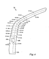
- a leading edge of the pillar 70 is denoted by 270 in Figure 4 and a trailing edge thereof by 280.
- Wall thickness data included in Figure 4 are in units of millimetres and are in respect of points of intersection of the axis A-A with the pillar 70 as depicted in Figure 3.
- Such spatially varying thickness is achieved either by appropriately adjusting dimensions of a tube blank or sheet blank to be subsequently hydroformed to form the pillar 70, or by machining the pillar 70 after hydroforming.
- Such adjustment of dimensions can be achieved by one or more of milling, grinding, selective rolling, or by selective adjustment of the hydroforming process itself such as employing differential pressure profiles during hydroforming.
- Hydroforming of the pillar 70 is of benefit in that it enables a complex thickness profile as illustrated to be achieved in mass production at acceptable cost. It is seen from Figure 4 that the pillar 70 is fabricated to have a greatest wall thickness, for example up to 5.7 millimetres thickness, at a lower portion of an inside exterior edge of the middle bend portion 120; when the pillar 70 has a nominal diameter of 150 mm, this corresponds to a wall-thickness/diameter ratio of substantially 3/50. Moreover, the middle bend portion 120 has a wall thickness which is generally greater than that of the lower portion 110 and especially the upper portion 130.
- a transition between the middle bend portion 120 and the upper portion 130 is on an outside exterior edge thereof of greatest wall thickness of substantially 4.9 millimetres as illustrated; when the pillar 70 has a nominal diameter of 150 mm, this corresponds to a wall-thickness/diameter ratio of 1/30.
- the lower portion 110 has a wall thickness of substantially 4 millimetres
- the middle bend portion 120 has a wall thickness of substantially 5 to 6 millimetres
- the upper portion 130 has a wall thickness of substantially 3 millimetres
- a thinnest wall thickness is utilized in the upper portion 130.
- the lower portion 110 has a wall-thicknessldiameter ratio of substantially 2t75
- the middle bend portion 120 has a wall-thickness/diameter ratio of substantially 11/300
- the upper portion has a wall-thickness/diameter ratio of substantially 1/50.
- Wall thicknesses presented in Figure 4 are found by the inventors, by applying a reduction process in deriving such wall thicknesses, to provide optimal protection against vehicle roll-over in crash or impact situations in which the vehicle 10 overturns.
- optimal wall thicknesses will be a function of nominal diameter of the pillar 70 and also its overall length.
- the pillar 70 preferably has a length in a range of 1.3 to 2 metres. Moreover, it preferably has a nominal diameter in a range of 5 cm to 25 cm, more optionally substantially 15 cm.
- the pillar 70 is susceptible to being hydroformed from a range of potential metals and metal alloys.
- cold-rolled steel and aluminium are described in the foregoing, alternative metals such as duralloy, titanium and stainless steel can be employed consistent with being sufficiently ductile to be susceptible to being hydroformed.
- FIG. 5 The performance results depicted in Figure 5 are also dependent upon the pillar 70 being able to couple stresses experienced at the pillar 70 especially during crash or impact to other regions of the vehicle 10. Such coupling of stress is pertinent to the end 135 of the pillar 70 whereat it is accommodated in the socket arrangement 85.
- the socket arrangement 85 is provide with curved surfaces in regions thereof progressing away from where the pillar 70 is received.
- Figure 6 concerns a socket arrangement indicated generally by 300 for receiving the pillar 70 at a mid-point along the sill 80, for example in a situation of a "B-pillar".
- the socket arrangement 300 includes an interface member including an aperture for receiving the end 135 of the pillar 70 with first and second curved load bearing regions 310, 320 respectively leading to the sill 80.
- a benefit of employing such curved load bearing regions 310, 320 is that abrupt stress-raising points are not introduced, such points potentially susceptible to give rise to a concentration of stress and hence susceptible to local fracture in crash or impact situations.
- the interface member is optionally integral with the sill 80.
- the interface member can be attached to the sill 80 by one or more fasteners 325, for example bolts, screws, rivets or similar.
- the interface member can be welded or brazed to the sill 80.
- the pillar 70 is secured to the aperture of the interface member, for example by way of fasteners or by seam or spot welding, or seam or spot brazing around a peripheral edge of the aforesaid aperture.
- FIG 7 there is shown a socket arrangement indicated generally by 330 for receiving the pillar 70 at a front end of the sill 80, for example in a situation of an "A-pillar" or potentially a “C-pillar".
- the socket arrangement 330 includes an interface member including an aperture for receiving the end 135 of the pillar 70 with a trailing curved load bearing region 340 leading to the sill 80.
- a benefit of employing such a curved load bearing region 340 is that abrupt stress-raising points are not introduced, such points potentially susceptible to giving rise to a concentration of stress and hence susceptible to local fracture in crash or impact situations.
- the interface member is shown to be integral with the sill 80; alternatively, it can be an end component added to the sill 80 in which case the interface member can be attached to the sill 80 by one or more fasteners, for example bolts, screws, rivets or similar. Yet alternatively, the interface member can be welded or brazed to the sill 80.
- the pillar 70 is secured to the aperture of the interface member, for example by way of fasteners or by seam or spot welding, or seam or spot brazing around a peripheral edge of the aforesaid aperture.
- the socket arrangements 300, 340 are also susceptible to being employed to receive rear "C-pillars", for example hydroformed rear pillars.
- C-pillars are, for example, employed to support rear windows of corresponding vehicles and for providing support to rear doors of a vehicle when four doors are included therein.
- the socket arrangements 330, 340 can be fabricated from at least one of metal, plastics material, composite material.
- the socket arrangements 330, 340 are conveniently fabricated from appropriate bent and formed sheet metal, for example sheet steel.
- the socket arrangements 330, 340 can be cast components.
- the socket arrangements are of tapered form as illustrated.
Abstract
Description
- The present invention relates to hydroformed automotive pillars, for example to front door-supporting pillars referred to as "A-pillars", to mid-vehicle supporting pillars referred to as "B-pillars", and to rear supporting pillars known as "C-pillars". Moreover, the present invention also relates to methods of including such hydroformed automotive pillars for providing vehicles with enhanced strength.
- When designing contemporary vehicles, automotive designers are faced with many compromises. One such compromise is weight of automotive components versus their mechanical strength versus their cost of production. In order to try to improve this particular compromise, ultralight steel automotive parts have recently been manufactured by employing hydroforming manufacturing processes. Simply stated, hydroforming employs water or hydraulic fluids at high pressure to provide forces for shaping a given component part. Hydroformed components can be generated either by forming metal sheet or metal tubing.
- Hydroforming of tubing is often employed when a complex automotive shape is required. For example, in a hydroforming process, a bent section of seam-welded cold-rolled steel tubing is placed in a closed die set, and then a pressurized fluid is introduced into ends of the tube, reshaping the tube to a confine of a cavity provided by the closed die set.
- Hydroforming of sheet steel is contemporarily implemented by two methods. In a first method, a steel sheet is deformed into a female cavity by water under pressure from a pump or by press action to generate a hydroformed component. In a second such method, a steel sheet is deformed by a male punch, which acts against a fluid under pressure. Sheet hydroforming provides a work-hardening effect as the steel sheet is forced against die surfaces by action of fluid pressure. Hydroforming provides aforementioned automotive designers with an opportunity to employ lighter thinner-gauge steels while maintaining component performance.
- It is known to fabricate side roof rails, front fender supports and pass-through members of automotive bodies by employing hydroforming processes. For example, in a published international patent application no.
PCT/CA98/00962 (WO 99/20516 - The aforementioned international PCT application concerns a vehicle Including a roof structure. In road vehicles devoid of a strengthening roof structure, for example in open-top road vehicles such as cabriolets and soft-top sports vehicles, it is not possible for associated automotive designers to rely on roof structures to provide vehicle occupant protection which represents a technical problem. Conventionally, it has been accepted that such open-top vehicles are potentially not as safe in crash or impact situations in comparison to vehicles including strengthening roof structures. Moreover, it has been appreciated by designers that remaining support pillars and members employed in manufacturing open-top vehicles need to be relatively stronger to provide at least an acceptable degree of protection for vehicle occupants; such strength not only concerns the support pillars themselves but also a manner in which they are incorporated into corresponding vehicles.
- An object of the invention is to provide an improved automotive support pillar arrangement for vehicles.
- According to a first aspect of the present invention, there is provided a hydroformed automotive pillar of unitary elongate construction, said pillar being of open or closed substantially tubular cross-section, said pillar having a first end and a second end, and said pillar being adapted when included in a road vehicle to continuously extend at the first end substantially from a longitudinal strengthening sill of the vehicle upwardly to the second end.
- The invention is of advantage in that the pillar extending from the sill is susceptible to impart to the vehicle increased protection against impact or crash.
- Preferable, the hydroformed automotive pillar is adapted to function as a front "A-pillar" for said vehicle. Such application of the pillar is of benefit in that such "A-pillars" are susceptible to experiencing considerable forces in front impact or vehicle roll-over situations. More preferably, the pillar is adapted to function as a front "A-pillar" for the vehicle implemented as an open-top road vehicle. Such application is of benefit in that a lack of roof structure in open-top vehicles potentially results in such "A-pillars" being subject to increased stress in impact or crash situations.
- Preferably, the hydroformed automotive pillar is adapted to function as mid-point "B-pillar" for said vehicle.
- Preferably, the hydroformed automotive pillar is adapted to function as a rear region "C-pillar' for said vehicle.
- Preferably, the hydroformed automotive pillar is adapted at its first end to engage into a socket arrangement associated with the sill. The socket arrangement is capable of assisting in convenient manufacture of the vehicle as well as rendering the vehicle better capable of supporting the pillar in impact and crash situations.
- Preferably, the hydroformed pillar is hydroformed from a metal sheet blank or from a tubular blank. More preferably, for convenient manufacture and for achieving desirable mechanical strength characteristics, the pillar is hydroformed from a cold-rolled steel sheet blank or from a cold-rolled steel tubular blank.
- Preferably, the hydroformed pillar is of asymmetrical cross-section. More preferably, the pillar includes a recess along an edge thereof for accommodating in operation an edge of a side window of the vehicle.
- Preferably, for example in a case of an "A-pillar, the hydroformed automotive pillar comprises in sequence a lower portion including said first end, a middle bend portion and an upper portion including said second end, said automotive pillar having a spatially varying wall thickness therealong with a greatest wall thickness at said middle bend portion relative to said upper portion and said lower portion. Such varying wall thickness is capable of providing a better comprise between a weight of the pillar and its mechanical strength. More preferably, in the hydroformed pillar, the middle bend portion has a relatively thicker wall thickness on a trailing edge thereof relative to a leading edge thereof.
- Preferably, in the hydroformed pillar, the upper portion is arranged in operation when included in a vehicle to be backwardly-curved and to provide support for a windscreen and a header of the vehicle.
- More preferably, in the hydroformed pillar, the lower portion has a wall thickness in a range of substantially 3.5 to 5.0 millimetres, the middle bend portion has a wall thickness in a range of substantially 4.0 to 5.7 millimetres, and the upper portion (130) has a wall thickness in a range of substantially 2.7 to 4.0 millimetres.
- More preferably, in the hydroformed pillar, the lower portion has a wall-thickness/diameter ratio in a range of substantially 7/300 to 1/30, the middle bend portion has a wall-thickness/diameter ratio in a range of substantially 2/75 to 7/450, and the upper portion has a wall thickness/diameter ratio in a range of substantially 8/450 to 2/75.
- According to a second aspect of the invention, there is provided a socket arrangement adapted to cooperate with a sill of a road vehicle and receive a hydroformed pillar according to the first aspect of the invention, said socket arrangement including an aperture for receiving said pillar and one or more substantially curved load-spreading regions included adjacent to said aperture for coupling forces borne by said pillar in impact or crash situations over a region of said sill.
- Preferably, the socket arrangement is integral with said sill- Such an implementation is susceptible to simplifying fabrication of the vehicle.
- Preferably, alternatively, the socket arrangement is a component adapted to be attached to said sill.
- Preferably, the socket arrangement includes a substantially curved load-spreading region adapted in operation to be backwardly or forwardly curved so as to render the socket arrangement operable to support said pillar implemented as an "A-pillar" or a "C-pillar".
- Preferably, the socket arrangement includes two substantially curved load-spreading regions adapted in operation to be backwardly and forwardly curved so as to render the socket arrangement operable to support said pillar implemented as a "B-pillar" or a "C-pillar". Such substantially curved load-spreading regions are capable of avoiding stress raisers which limit a degree of stress under impact or crash situations that the socket arrangement is capable of bearing.
- Preferably, the socket arrangement is adapted to be attached to said pillar by at least one of: brazing, welding, application of one or more fasteners. Such attachment is capable of assisting the pillar to remain engaged with the socket arrangement during impact or crash situations.
- According to a third aspect of the invention, there is provided a method of providing a vehicle with enhanced strength to resist vehicle roll-over, said method including steps of:
- (a) hydroforming one or more pillars, each pillar being of unitary elongate construction and including a first end and a second end; and
- (b) including said one or more pillars in the vehicle so as to upwardly extend from the first end engaged with a longitudinal sill of said vehicle to the second end.
- Preferably, the method includes a step of adapting the sill to include a socket arrangement for receiving each of said one or more pillars, said socket arrangement comprising an aperture for receiving said first end of each said one or more pillars and one or more substantially curved load-spreading regions included adjacent to said aperture for coupling forces borne by said one or more pillars in impact or crash situations over a region of said sill.
- Preferably, the method includes a further step of hydroforming said one or more pillars to have a spatially varying wall thickness. More preferably, the method is implemented such that said wall thickness is spatially greatest where said one or more pillars are expected to be subjected to greatest stress during vehicle roll-over.
- Preferably, in step (a) of the method, the one or more pillars are fabricated by hydroforming metal sheet blanks or metal tube blanks. More preferably, in step (a), the one or more pillars are fabricated by hydroforming cold-rolled steel sheet blanks or cold-rolled steel tube blanks.
- According to a fourth aspect of the invention, there is provided a hydroformed automotive pillar arrangement operable to provide impact or crash protection in a vehicle, said arrangement including one or more hydroformed pillars, each pillar being of unitary elongate construction, each pillar being of open or closed substantially tubular cross-section, each pillar having a first end and a second end, and each pillar being adapted when included in the vehicle to continuously extend at the first end substantially from a socket arrangement coupled to a longitudinal strengthening sill of the vehicle upwardly to the second end.
- Preferably, in the automotive pillar arrangement, the socket arrangement comprises an aperture for receiving said first end of each said one or more pillars, and one or more substantially curved load-spreading regions included adjacent to said aperture for coupling forces borne by said one or more pillars in impact or crash situations over a region of said sill.
- It will be appreciated that features of the invention are susceptible to being combined in any combination without departing from the scope of the invention as defined by the appended claims.
- By way of example only, embodiments of the invention will now be described with reference to the accompanying drawings wherein:
- Figure 1
- is a schematic perspective illustration of a front portion of an open-top road vehicle, wherein certain vehicle parts are not illustrated so as to highlight a front substantially vertical pillar, known as an "A-pillar", providing strength to a windscreen and associated top header of the vehicle;
- Figure 2
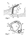
- is a schematic side illustration of a part of the vehicle in Figure 1, the side illustration further showing a position of the "A-pillar" within the vehicle;
- Figure 3
- is an illustration of a section A-A through the "A-pillar" of the vehicle shown in Figure 2;
- Figure 4
- is a side view of the "A-pillar" of the vehicle in Figure 1, wherein variations in wall thickness along the "A-pillar" are shown, especially in a region of the "A-pillar" most subject to mechanical stress under potential impact or crash situations;
- Figure 5
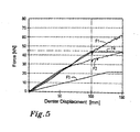
- is a graph providing mechanical strength characteristics of the "A-pillar" illustrating in Figures 2 and 4;
- Figure 6
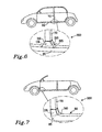
- is a sketch diagram Illustrating an arrangement for accommodating a "B-pillar", for example Implemented as a hydroformed pillar, at its lower end in a socket arrangement associated with a sill of the vehicle; and
- Figure 7
- is a sketch diagram illustrating an arrangement for accommodating an "A-pillar", for example implemented as a hydroformed pillar, at its lower end in a socket arrangement associated with a sill of the vehicle.
- Referring to Figure 1, there is shown a front portion of an open-top road vehicle indicated generally by 10. The
vehicle 10 comprises afront bumper support 20, anengine compartment 30 and awheel arch 40; however, a corresponding engine and wheel are not shown but nevertheless form a part of thevehicle 10. Moreover, thevehicle 10 includes awindscreen 50 which is supported at its top edge by aheader 60. Theheader 60 is itself supported on two front support pillars known as "A-pillars" which extend continuously substantially from theheader 60 and downwardly tohorizontal sills 80 on each right and left sides of thevehicle 10. A left-hand front support pillar is illustrated in cross-hatch and is denoted by 70. A right-hand front support pillar (not shown in Figure 1) is substantially a mirror version of its left-handfront support pillar 70. Eachsill 80 is coupled at a front end thereof to itscorresponding support pillar 70 and further back therealong to its corresponding rear support pillar denoted by 90; therear support pillar 90 is also referred to as being a "B"-pillar. Further back, thevehicle 10 optionally includes left- and right-side "C-pillars" prior to a rear luggage compartment of thevehicle 10; the "C-pillar" is conveniently provided with a socket arrangement with forwardly-curved load spreading surfaces as elucidated later. Thevehicle 10 further comprises alateral strengthening member 100 extending between the tworear support pillars 90. - At a front end of the
sill 80, there is provided asocket arrangement 85 for receiving alower end 135 of thesupport pillar 70. Thesocket arrangement 85 is not only convenient during assembly of thevehicle 10 but is effective at distributing load more evenly from thesupport pillar 70 to thesill 80 in crash or impact situations. - In Figure 2, the
support pillar 70 is shown in enlarged side view and comprises alower portion 110 whose central longitudinal axis is substantially vertical in orientation in operation, amiddle bend portion 120 and anupper portion 130; theupper portion 130 is optionally gently backwardly-curved. Thelower portion 110 includes thelower end 135 at an extremity thereof. In practice, thesupport pillar 70 is optionally retained within the socket arrangement of thesill 80 by at least one of: abutment, welding, brazing, use of fasteners. Such fasteners include, for example, one or more of bolts, rivets, press-studs, screws or similar. In Figure 2, there is also shown a cross-section A-A which is relevant for wall-thickness measurements depicted in Figure 4. - In a crash or impact situation, for example in a situation wherein the
vehicle 10 overturns such that the weight of thevehicle 10 is borne primarily by theheader 60, thewindscreen 50 itself cannot be relied upon to provide a high degree of support. Thus, the weight of thevehicle 10 in such an overturned state, namely in a vehicle "roll-over" situation, is borne via theheader 60 through the twosupport pillars 70 to the twolateral sills 80 and its associatedlateral strengthening member 100. Whereas theheader 60 may potentially become deformed in such a crash or impact situation, it is important that thesupport pillars 70 remain intact to provide protection to occupants of thevehicle 10. In particular, in such an impact of crash situation, themiddle bend portion 120 is subject to considerable bending moments causing not only metalwork at a front region on thevehicle 10 to be in tensive stress, but also thesill 80 to be in longitudinal tensive stress. Thesocket arrangement 85 is designed so as to be able to bear such tensive stress as experienced by thesill 80. - In order to provide sufficient strength in crash or impact situations, the
front support pillars 70 of thevehicle 10 are specially fabricated to be sufficiently strong when continuously extending substantially from theheader 60 to thesill 80. In Figure 3, a cross-section through the axis A-A is shown. In the cross-section, there is shown thewindscreen 50 and also aside window 210 of a door of thevehicle 10. The cross-section also includes anouter metal skin 220 included primarily for aesthetic purposes and to protect thesupport pillar 70 from precipitation, for example rain, which could cause rusting of thepillar 70. The cross-section also includes aninner trim 240 which is susceptible to being implemented as a metal sheet or plastics material part. A rubber or similarelastic material surround 230 is included to provide a weather seal for thewindscreen 50 to theouter metal skin 220. Plastics material rivets or similar types of fasteners as denoted by 250 are included at intervals along thepillar 70 to retain theinner trim 240 onto thepillar 70. Thepillar 70 is hydroformed from metal sheet or metal tubing on account of its relatively complex geometrical shape; when hydroformed from metal tubing, thepillar 70 is said to be of "closed" form; alternatively, when hydroformed from metal sheet, thepillar 70 is referred to as being of "open" form and may in such case include a longitudinal slot along at least part of its length on account of the metal sheet being curved into a substantially tubular format. The metal sheet or metal tubing is beneficially cold-rolled steel, although other materials such as stainless steel, titanium, titanium alloy, aluminium, duralloy and aluminium alloy can be used for fabricating thepillar 70. Thepillar 70 can, for example, be recessed along its edge to provide a space for accommodating theside window 210 and theouter metal skin 220 as illustrated. Moreover, thepillar 70 optionally has an asymmetrical cross-section as illustrated, although it can be alternatively rendered symmetrical in cross-section. - The
pillar 70 not only is required to be sufficiently strong in operation, for example in a crash or impact situation, but also not to add excessively to weight of thevehicle 10 as excess weight can affect cost of manufacturing thevehicle 10, can affect the vehicle's 10 handling performance such as acceleration, and can have implications for a suspension mechanism of thevehicle 10. In order to impart eachpillar 70 of thevehicle 10 with best operative performance, wall thickness of thepillar 70 is rendered spatially variable in a manner as depicted in Figure 4 for the pillar fabricated from cold-rolled steel. The wall thickness varies spatially in a continuous manner not only along thepillar 70 but also around thepillar 70 when fabricated from a tubular blank, but is depicted in Figure 4 as average thickness over spatial regions of thepillar 70 as shown for convenience of presentation. For reference, a leading edge of thepillar 70 is denoted by 270 in Figure 4 and a trailing edge thereof by 280. Wall thickness data included in Figure 4 are in units of millimetres and are in respect of points of intersection of the axis A-A with thepillar 70 as depicted in Figure 3. Such spatially varying thickness is achieved either by appropriately adjusting dimensions of a tube blank or sheet blank to be subsequently hydroformed to form thepillar 70, or by machining thepillar 70 after hydroforming. Such adjustment of dimensions can be achieved by one or more of milling, grinding, selective rolling, or by selective adjustment of the hydroforming process itself such as employing differential pressure profiles during hydroforming. Hydroforming of thepillar 70 is of benefit in that it enables a complex thickness profile as illustrated to be achieved in mass production at acceptable cost. It is seen from Figure 4 that thepillar 70 is fabricated to have a greatest wall thickness, for example up to 5.7 millimetres thickness, at a lower portion of an inside exterior edge of themiddle bend portion 120; when thepillar 70 has a nominal diameter of 150 mm, this corresponds to a wall-thickness/diameter ratio of substantially 3/50. Moreover, themiddle bend portion 120 has a wall thickness which is generally greater than that of thelower portion 110 and especially theupper portion 130. A transition between themiddle bend portion 120 and theupper portion 130 is on an outside exterior edge thereof of greatest wall thickness of substantially 4.9 millimetres as illustrated; when thepillar 70 has a nominal diameter of 150 mm, this corresponds to a wall-thickness/diameter ratio of 1/30. Thus, whereas, thelower portion 110 has a wall thickness of substantially 4 millimetres, themiddle bend portion 120 has a wall thickness of substantially 5 to 6 millimetres, and theupper portion 130 has a wall thickness of substantially 3 millimetres, a thinnest wall thickness is utilized in theupper portion 130. in terms of a ratio of diameter of thepillar 70 to its wall thickness, the diameter being taken to be substantially 150 mm, thelower portion 110 has a wall-thicknessldiameter ratio of substantially 2t75, themiddle bend portion 120 has a wall-thickness/diameter ratio of substantially 11/300, and the upper portion has a wall-thickness/diameter ratio of substantially 1/50. Wall thicknesses presented in Figure 4 are found by the inventors, by applying a reduction process in deriving such wall thicknesses, to provide optimal protection against vehicle roll-over in crash or impact situations in which thevehicle 10 overturns. However, it will be appreciated that optimal wall thicknesses will be a function of nominal diameter of thepillar 70 and also its overall length. Thepillar 70 preferably has a length in a range of 1.3 to 2 metres. Moreover, it preferably has a nominal diameter in a range of 5 cm to 25 cm, more optionally substantially 15 cm. - In Figure 5, performance results for the
pillars 70 in thevehicle 10 are presented. There is shown a graph comprising an abscissa axis denoting Denter displacement at an upper region of thepillar 70 in units of millimetres in response to applied force as denoted along an ordinate axis; the ordinate axis has units of kilo Newtons (kN). There are shown a series of curves F1 to F4 from experiments and simulations which indicate that thepillar 70 undergoes a displacement of substantially 100 millimetres when a force of 45 kN is applied to thepillar 70. Such a displacement performance is susceptible to providing occupants of thevehicle 10 with a high degree of protection from being injured when thevehicle 10 is in operation and subjected to a crash situation. - As elucidated briefly in the foregoing, the
pillar 70 is susceptible to being hydroformed from a range of potential metals and metal alloys. Although cold-rolled steel and aluminium are described in the foregoing, alternative metals such as duralloy, titanium and stainless steel can be employed consistent with being sufficiently ductile to be susceptible to being hydroformed. - The performance results depicted in Figure 5 are also dependent upon the
pillar 70 being able to couple stresses experienced at thepillar 70 especially during crash or impact to other regions of thevehicle 10. Such coupling of stress is pertinent to theend 135 of thepillar 70 whereat it is accommodated in thesocket arrangement 85. In order to cope with impact or crash stresses, thesocket arrangement 85 is provide with curved surfaces in regions thereof progressing away from where thepillar 70 is received. For example, Figure 6 concerns a socket arrangement indicated generally by 300 for receiving thepillar 70 at a mid-point along thesill 80, for example in a situation of a "B-pillar". Thesocket arrangement 300 includes an interface member including an aperture for receiving theend 135 of thepillar 70 with first and second curvedload bearing regions sill 80. A benefit of employing such curvedload bearing regions sill 80. Alternatively, the interface member can be attached to thesill 80 by one ormore fasteners 325, for example bolts, screws, rivets or similar. Yet alternatively, the interface member can be welded or brazed to thesill 80. Optionally, thepillar 70 is secured to the aperture of the interface member, for example by way of fasteners or by seam or spot welding, or seam or spot brazing around a peripheral edge of the aforesaid aperture. - In Figure 7, there is shown a socket arrangement indicated generally by 330 for receiving the
pillar 70 at a front end of thesill 80, for example in a situation of an "A-pillar" or potentially a "C-pillar". Thesocket arrangement 330 includes an interface member including an aperture for receiving theend 135 of thepillar 70 with a trailing curvedload bearing region 340 leading to thesill 80. A benefit of employing such a curvedload bearing region 340 is that abrupt stress-raising points are not introduced, such points potentially susceptible to giving rise to a concentration of stress and hence susceptible to local fracture in crash or impact situations. The interface member is shown to be integral with thesill 80; alternatively, it can be an end component added to thesill 80 in which case the interface member can be attached to thesill 80 by one or more fasteners, for example bolts, screws, rivets or similar. Yet alternatively, the interface member can be welded or brazed to thesill 80. Optionally, thepillar 70 is secured to the aperture of the interface member, for example by way of fasteners or by seam or spot welding, or seam or spot brazing around a peripheral edge of the aforesaid aperture. - The
socket arrangements - The
socket arrangements socket arrangements socket arrangements - It will be appreciated that embodiments of the invention described in the foregoing are susceptible to being modified without departing from the scope of the invention as defined by the accompanying claims.
- Numerals included within parentheses in the accompanying claims are included to assist appreciation of subject matter claimed in the accompanying claims and are not intended to limit scope of the claims.
- Expressions such as "comprise", "include", "consist of", "incorporate", "have" and "is" are intended to be construed non-exclusively, namely such expressions do not exclude other components, items or elements being present which are not explicitly described or disclosed. Reference to the plural is to be construed also to refer to the singular and vice versa.
Claims (29)
- A hydroformed automotive pillar (70) of unitary elongate construction, said pillar (70) being of open or closed substantially tubular cross-section, said pillar (70) having a first end (135) and a second end, and said pillar (70) being adapted when included in a road vehicle (10) to continuously extend at the first end (135) substantially from a longitudinal strengthening sill (80) of the vehicle (10) upwardly to the second end.
- A hydroformed automotive pillar (70) as claimed in claim 1, said pillar (70) being adapted to function as a front "A-pillar" for said vehicle (10).
- A hydroformed pillar (70) according to claim 2, said pillar (70) being adapted to function as a front "A-pillar" for said vehicle (10) implemented as an open-top road vehicle (10).
- A hydroformed automotive pillar (70) as claimed in claim 1, said pillar (70) being adapted to function as mid-point "B-pillar" for said vehicle (10).
- A hydroformed automotive pillar (70) as claimed in claim 1, said pillar (70) being adapted to function as a rear region "C-pillar" for said vehicle (10).
- A hydroformed automotive pillar (70) as claimed in any one of claims 1 to 5, wherein said pillar (70) is adapted at its first end (135) to engage into a socket arrangement (300, 330) associated with the sill (80).
- A hydroformed pillar (70) as claimed in any one of the preceding claims, wherein the pillar (70) is hydroformed from a metal sheet blank or from a tubular blank.
- A hydroformed pillar (70) as claimed in claim 7, wherein the pillar (70) is hydroformed from a cold-rolled steel sheet blank or from a cold-rolled steel tubular blank.
- A hydroformed pillar (70) as claimed in any one of the preceding claims, wherein pillar (70) is of asymmetrical cross-section.
- A hydroformed pillar (70) as claimed in claim 9, wherein the pillar (70) includes a recess along an edge thereof for accommodating in operation an edge of a side window (210) of the vehicle (10).
- A hydroformed automotive pillar (70) as claimed in claim 2, wherein, said pillar (70) comprising in sequence a lower portion (110) including said first end (135), a middle bend portion (120) and an upper portion (130) including said second end, said automotive pillar (70) having a spatially varying wall thickness therealong with a greatest wall thickness at said middle bend portion (120) relative to said upper portion (130) and said lower portion (120).
- A hydroformed pillar (70) as claimed in claim 11, wherein the middle bend portion (120) has a relatively thicker wall thickness on a trailing edge (280) thereof relative to a leading edge (270) thereof.
- A hydroformed pillar (70) as claimed in claim 11 or 12, wherein the upper portion (130) is arranged in operation when included in a vehicle (10) to be backwardly-curved and to provide support for a windscreen (50) and a header (60) of the vehicle (10).
- A hydroformed pillar (70) as claimed in claim 11, 12 or 13, wherein the lower portion (110) has a wall thickness in a range of substantially 3.5 to 5.0 millimetres, the middle bend portion (120) has a wall thickness in a range of substantially 4.0 to 5.7 millimetres, and the upper portion (130) has a wall thickness in a range of substantially 2.7 to 4.0 millimetres.
- A hydroformed pillar (70) as claimed in claim 11, 12, 13 or 14, wherein the lower portion (110) has a wall-thickness/diameter ratio in a range of substantially 7/300 to 1/30, the middle bend portion (120) has a wall-thickness/diameter ratio in a range of substantially 2/75 to 7/450, and the upper portion (130) has a wall-thickness/diameter ratio in a range of substantially 8/450 to 2/75.
- A socket arrangement (300, 330) adapted to cooperate with a sill (80) of a road vehicle (10) and receive a hydroformed pillar (70) as claimed in any one of claims 1 to 15, said socket arrangement (300, 330) including an aperture for receiving said pillar (70) and one or more substantially curved load-spreading regions (310, 320; 340) included adjacent to said aperture for coupling forces borne by said pillar (70) in impact or crash situations over a region of said sill (80).
- A socket arrangement (300, 330) as claimed in claim 16, wherein said socket arrangement (300, 330) is integral with said sill (80).
- A socket arrangement (300, 330) as claimed in claim 16, wherein said socket arrangement (300, 330) is a component adapted to be attached to said sill (80).
- A socket arrangement (330) as claimed in any one of claims 16 to 18, wherein the socket arrangement (330) includes a substantially curved load-spreading region adapted in operation to be backwardly or forwardly curved so as to render the socket arrangement (330) operable to support said pillar (70) implemented as an "A-pillar" or a "C-pillar",
- A socket arrangement (330) as claimed in any one of claims 16 to 18, wherein the socket arrangement (330) includes two substantially curved load-spreading regions adapted in operation to be backwardly and forwardly curved so as to render the socket arrangement (330) operable to support said pillar (70) implemented as a "B-pillar" or a "C-pillar".
- A socket arrangement (300. 330) as claimed in any one of claims 16 to 20, wherein the socket arrangement (330) is adapted to be attached to said pillar (70) by at least one of: brazing, welding, application of one or more fasteners.
- A method of providing a vehicle (10) with enhanced strength to resist vehicle roll-over, said method including steps of:(a) hydroforming one or more pillars (70), each pillar (70) being of unitary elongate construction and including a first end (135) and a second end; and(b) including said one or more pillars (70) in the vehicle (10) so as to upwardly extend from the first end (135) engaged with a longitudinal sill (80) of said vehicle (10) to the second end.
- A method as claimed in claim 22, including a step of adapting the sill (80) to include a socket arrangement (300, 330) for receiving each of said one or more pillars (70), said socket arrangement (300, 330) comprising an aperture for receiving said first end (135) of each said one or more pillars (70) and one or more substantially curved load-spreading regions (310, 320; 340) included adjacent to said aperture for coupling forces borne by said one or more pillars (70) in impact or crash situations over a region of said sill (80).
- A method as claimed in claim 22 or 23, including a further step of hydroforming said one or more pillars (70) to have a spatially varying wall thickness.
- A method as claimed in claim 24, wherein said wall thickness is spatially greatest where said one or more pillars (70) are expected to be subjected to greatest stress during vehicle roll-over.
- A method as claimed in claim 24 or 25, wherein in step (a) the one or more pillars (70) are fabricated by hydroforming metal sheet blanks or metal tube blanks.
- A method as claimed in claim 26, wherein in step (a) the one or more pillars (70) are fabricated by hydroforming cold-rolled steel sheet blanks or cold-rolled steel tube blanks.
- A hydroformed automotive pillar arrangement (70, 300, 330) operable to provide impact or crash protection in a vehicle (10), said arrangement including one or more hydroformed pillars (70), each pillar (70) being of unitary elongate construction, each pillar (70) being of open or closed substantially tubular cross-section, each pillar (70) having a first end (135) and a second end, and each pillar (70) being adapted when included in the vehicle (10) to continuously extend at the first end (135) substantially from a socket arrangement (300, 330) coupled to a longitudinal strengthening sill (80) of the vehicle (10) upwardly to the second end.
- An automotive pillar arrangement (70, 300, 330) as claimed in claim 28, wherein said socket arrangement (300, 330) comprises an aperture for receiving said first end (135) of each said one or more pillars (70) and one or more substantially curved load-spreading regions (310, 320; 340) included adjacent to said aperture for coupling forces borne by said one or more pillars (70) in impact or crash situations over a region of said sill (80).
Priority Applications (3)
| Application Number | Priority Date | Filing Date | Title |
|---|---|---|---|
| EP05019526A EP1762467B1 (en) | 2005-09-08 | 2005-09-08 | Hydroformed automotive pillar |
| DE602005013524T DE602005013524D1 (en) | 2005-09-08 | 2005-09-08 | Hydroformed motor vehicle pillar |
| US11/530,293 US8517458B2 (en) | 2005-09-08 | 2006-09-08 | Hydroformed automotive pillar |
Applications Claiming Priority (1)
| Application Number | Priority Date | Filing Date | Title |
|---|---|---|---|
| EP05019526A EP1762467B1 (en) | 2005-09-08 | 2005-09-08 | Hydroformed automotive pillar |
Publications (2)
| Publication Number | Publication Date |
|---|---|
| EP1762467A1 true EP1762467A1 (en) | 2007-03-14 |
| EP1762467B1 EP1762467B1 (en) | 2009-03-25 |
Family
ID=35589489
Family Applications (1)
| Application Number | Title | Priority Date | Filing Date |
|---|---|---|---|
| EP05019526A Active EP1762467B1 (en) | 2005-09-08 | 2005-09-08 | Hydroformed automotive pillar |
Country Status (3)
| Country | Link |
|---|---|
| US (1) | US8517458B2 (en) |
| EP (1) | EP1762467B1 (en) |
| DE (1) | DE602005013524D1 (en) |
Cited By (2)
| Publication number | Priority date | Publication date | Assignee | Title |
|---|---|---|---|---|
| DE102008056272A1 (en) * | 2008-11-06 | 2010-05-12 | Volkswagen Ag | Chassis pillar, particularly A-pillar for use in automobile, particularly cabriolet-vehicle, is allotted with two or multiple bending points with different bending resistances adjustable according to adjacent material regions |
| DE102010017658A1 (en) * | 2010-06-30 | 2012-01-05 | Dr. Ing. H.C. F. Porsche Aktiengesellschaft | Hollow section, particularly column, for support structure of motor vehicle, has reinforcing pipe that is arranged in inner side of hollow section, where reinforcing pipe is hollow from inner side |
Families Citing this family (20)
| Publication number | Priority date | Publication date | Assignee | Title |
|---|---|---|---|---|
| KR100844563B1 (en) * | 2006-12-13 | 2008-07-08 | 현대자동차주식회사 | Front pillar apparatus |
| US20090174219A1 (en) * | 2008-01-04 | 2009-07-09 | Foreman Grant G | Vehicle energy absorber structure and method |
| WO2012157079A1 (en) * | 2011-05-17 | 2012-11-22 | トヨタ自動車株式会社 | Vehicle body framework structure |
| DE102011052291B4 (en) * | 2011-07-29 | 2016-03-10 | Benteler Automobiltechnik Gmbh | Motor vehicle component and method for producing a motor vehicle component |
| US9139235B2 (en) | 2013-05-21 | 2015-09-22 | Ford Global Technologies, Llc | Vehicle frame rail and pillar connection |
| KR102008678B1 (en) * | 2013-12-04 | 2019-08-08 | 현대자동차 주식회사 | Vehicle body frame unit |
| US9248868B2 (en) | 2014-05-29 | 2016-02-02 | Ford Global Technologies, Llc | Vehicle front end structure |
| US9114835B1 (en) | 2014-05-29 | 2015-08-25 | Ford Global Technologies, Llc | Vehicle front end structure |
| US9079617B1 (en) | 2014-05-29 | 2015-07-14 | Ford Global Technologies, Llc | Vehicle front end joint |
| DE102014216225A1 (en) * | 2014-08-14 | 2016-02-18 | Muhr Und Bender Kg | Structural component and method for producing a structural component |
| DE102015205402B4 (en) * | 2015-03-25 | 2023-06-22 | Bayerische Motoren Werke Aktiengesellschaft | Body structure with one-piece B-pillar reinforcements designed as curved tubes, as well as correspondingly designed B-pillar reinforcements |
| US9365242B1 (en) | 2015-05-13 | 2016-06-14 | Ford Global Technologies, Llc | Tubular vehicle roof pillar reinforcement |
| KR101738039B1 (en) * | 2015-10-23 | 2017-05-19 | 현대자동차주식회사 | Structure of hybrid-front pillar |
| DE102016101158B3 (en) * | 2016-01-22 | 2017-06-08 | Benteler Automobiltechnik Gmbh | Method for producing a longitudinal member |
| USD785504S1 (en) * | 2016-05-05 | 2017-05-02 | Fab Fours Inc. | Windshield protector |
| US10385900B2 (en) * | 2017-03-24 | 2019-08-20 | Ford Global Technologies, Llc | Reduced diameter head rivet |
| JP6898169B2 (en) * | 2017-08-02 | 2021-07-07 | トヨタ自動車株式会社 | Body skeletal structure |
| JP2019073202A (en) * | 2017-10-18 | 2019-05-16 | トヨタ自動車株式会社 | Front pillar |
| JP7139826B2 (en) * | 2018-09-21 | 2022-09-21 | トヨタ自動車株式会社 | Front pillar and manufacturing method thereof |
| CN112407057A (en) * | 2020-12-01 | 2021-02-26 | 的卢技术有限公司 | Automobile body reinforcing structure and mounting method |
Citations (8)
| Publication number | Priority date | Publication date | Assignee | Title |
|---|---|---|---|---|
| EP0631924A1 (en) * | 1993-07-02 | 1995-01-04 | Honda Giken Kogyo Kabushiki Kaisha | Frame forming member |
| EP0862956A1 (en) * | 1997-03-05 | 1998-09-09 | Daimler-Benz Aktiengesellschaft | Hollow beam for a car body and method of producing the same by internal high pressure forming |
| US5839777A (en) * | 1995-05-26 | 1998-11-24 | Dr. Ing. H.C.F. Porsche Ag | Support of a body structure of a vehicle and process for manufacturing same |
| WO1999020516A1 (en) | 1997-10-16 | 1999-04-29 | Cosma International Inc. | Hydroformed space frame and method of manufacturing the same |
| US20010000119A1 (en) * | 1997-10-16 | 2001-04-05 | Jaekel Federico G. | Hydroformed space frame and joints therefor |
| US20010002760A1 (en) * | 1997-10-16 | 2001-06-07 | Gianfranco Gabbianelli | Door seal interface structure for a motor vehicle space frame |
| US20040166354A1 (en) * | 2003-02-17 | 2004-08-26 | Bernd Schulze | Hollow molded part with closed cross-section and a reinforcement |
| WO2004078563A1 (en) * | 2003-03-07 | 2004-09-16 | Wilhelm Karmann Gmbh | Motor vehicle body pillar |
Family Cites Families (5)
| Publication number | Priority date | Publication date | Assignee | Title |
|---|---|---|---|---|
| IT1165208B (en) * | 1979-05-25 | 1987-04-22 | Fiat Auto Spa | SUPPORTING FRAME FOR MOTOR VEHICLES |
| GB2271967B (en) * | 1992-11-02 | 1996-10-23 | Honda Motor Co Ltd | Automobile bumper and injection mold for forming such automobile bumper |
| EP1106484B1 (en) * | 1999-11-30 | 2008-05-21 | Honda Giken Kogyo Kabushiki Kaisha | Vehicle front pillar |
| JP4294818B2 (en) * | 1999-12-03 | 2009-07-15 | 本田技研工業株式会社 | Car front pillar |
| DE10357927B4 (en) * | 2003-12-11 | 2007-07-26 | Daimlerchrysler Ag | A-pillar for a motor vehicle |
-
2005
- 2005-09-08 DE DE602005013524T patent/DE602005013524D1/en active Active
- 2005-09-08 EP EP05019526A patent/EP1762467B1/en active Active
-
2006
- 2006-09-08 US US11/530,293 patent/US8517458B2/en active Active
Patent Citations (8)
| Publication number | Priority date | Publication date | Assignee | Title |
|---|---|---|---|---|
| EP0631924A1 (en) * | 1993-07-02 | 1995-01-04 | Honda Giken Kogyo Kabushiki Kaisha | Frame forming member |
| US5839777A (en) * | 1995-05-26 | 1998-11-24 | Dr. Ing. H.C.F. Porsche Ag | Support of a body structure of a vehicle and process for manufacturing same |
| EP0862956A1 (en) * | 1997-03-05 | 1998-09-09 | Daimler-Benz Aktiengesellschaft | Hollow beam for a car body and method of producing the same by internal high pressure forming |
| WO1999020516A1 (en) | 1997-10-16 | 1999-04-29 | Cosma International Inc. | Hydroformed space frame and method of manufacturing the same |
| US20010000119A1 (en) * | 1997-10-16 | 2001-04-05 | Jaekel Federico G. | Hydroformed space frame and joints therefor |
| US20010002760A1 (en) * | 1997-10-16 | 2001-06-07 | Gianfranco Gabbianelli | Door seal interface structure for a motor vehicle space frame |
| US20040166354A1 (en) * | 2003-02-17 | 2004-08-26 | Bernd Schulze | Hollow molded part with closed cross-section and a reinforcement |
| WO2004078563A1 (en) * | 2003-03-07 | 2004-09-16 | Wilhelm Karmann Gmbh | Motor vehicle body pillar |
Cited By (2)
| Publication number | Priority date | Publication date | Assignee | Title |
|---|---|---|---|---|
| DE102008056272A1 (en) * | 2008-11-06 | 2010-05-12 | Volkswagen Ag | Chassis pillar, particularly A-pillar for use in automobile, particularly cabriolet-vehicle, is allotted with two or multiple bending points with different bending resistances adjustable according to adjacent material regions |
| DE102010017658A1 (en) * | 2010-06-30 | 2012-01-05 | Dr. Ing. H.C. F. Porsche Aktiengesellschaft | Hollow section, particularly column, for support structure of motor vehicle, has reinforcing pipe that is arranged in inner side of hollow section, where reinforcing pipe is hollow from inner side |
Also Published As
| Publication number | Publication date |
|---|---|
| US8517458B2 (en) | 2013-08-27 |
| DE602005013524D1 (en) | 2009-05-07 |
| EP1762467B1 (en) | 2009-03-25 |
| US20070063546A1 (en) | 2007-03-22 |
Similar Documents
| Publication | Publication Date | Title |
|---|---|---|
| EP1762467B1 (en) | Hydroformed automotive pillar | |
| EP2529997B1 (en) | Vehicle roof support pillar assembly | |
| EP1363826B1 (en) | Hybrid space frame for motor vehicle | |
| EP1441940B1 (en) | Modular underbody for a motor vehicle | |
| JP4636799B2 (en) | Support structure made of hollow steel long section material for automobile | |
| US9630653B2 (en) | Vehicle body structure | |
| US6412818B1 (en) | Vehicle body and frame assembly and method of manufacturing same | |
| US7585017B2 (en) | One-piece, tubular member with an integrated welded flange and associated method for producing | |
| US20120313400A1 (en) | Vehicle pillar assembly | |
| US20190185073A1 (en) | Pickup Box D-Pillar Assembly | |
| JP2005532207A5 (en) | ||
| US20120261950A1 (en) | Vehicle roof support assembly | |
| US6138358A (en) | Method of manufacturing a vehicle body and frame assembly | |
| US9248862B1 (en) | Vehicle body structure | |
| US6681488B2 (en) | Method of manufacturing a vehicle body and frame assembly | |
| US6519855B1 (en) | Method of manufacturing a vehicle body and frame assembly | |
| EP3597512B1 (en) | Molded body, structural member, and method for manufacturing molded body | |
| EP1942045B1 (en) | Method for manufacturing a pillar for a vehicle | |
| JP3773094B2 (en) | Rear body structure of the vehicle | |
| EP1870318A1 (en) | Vehicle pillar and vehicle | |
| EP1738998A1 (en) | Method for assembling a vehicle body |
Legal Events
| Date | Code | Title | Description |
|---|---|---|---|
| PUAI | Public reference made under article 153(3) epc to a published international application that has entered the european phase |
Free format text: ORIGINAL CODE: 0009012 |
|
| AK | Designated contracting states |
Kind code of ref document: A1 Designated state(s): AT BE BG CH CY CZ DE DK EE ES FI FR GB GR HU IE IS IT LI LT LU LV MC NL PL PT RO SE SI SK TR |
|
| AX | Request for extension of the european patent |
Extension state: AL BA HR MK YU |
|
| 17P | Request for examination filed |
Effective date: 20070914 |
|
| AKX | Designation fees paid |
Designated state(s): DE GB SE |
|
| 17Q | First examination report despatched |
Effective date: 20080204 |
|
| GRAP | Despatch of communication of intention to grant a patent |
Free format text: ORIGINAL CODE: EPIDOSNIGR1 |
|
| GRAC | Information related to communication of intention to grant a patent modified |
Free format text: ORIGINAL CODE: EPIDOSCIGR1 |
|
| GRAC | Information related to communication of intention to grant a patent modified |
Free format text: ORIGINAL CODE: EPIDOSCIGR1 |
|
| GRAS | Grant fee paid |
Free format text: ORIGINAL CODE: EPIDOSNIGR3 |
|
| GRAA | (expected) grant |
Free format text: ORIGINAL CODE: 0009210 |
|
| AK | Designated contracting states |
Kind code of ref document: B1 Designated state(s): DE GB SE |
|
| REG | Reference to a national code |
Ref country code: GB Ref legal event code: FG4D |
|
| REF | Corresponds to: |
Ref document number: 602005013524 Country of ref document: DE Date of ref document: 20090507 Kind code of ref document: P |
|
| REG | Reference to a national code |
Ref country code: SE Ref legal event code: TRGR |
|
| PLBE | No opposition filed within time limit |
Free format text: ORIGINAL CODE: 0009261 |
|
| STAA | Information on the status of an ep patent application or granted ep patent |
Free format text: STATUS: NO OPPOSITION FILED WITHIN TIME LIMIT |
|
| 26N | No opposition filed |
Effective date: 20091229 |
|
| REG | Reference to a national code |
Ref country code: GB Ref legal event code: 732E Free format text: REGISTERED BETWEEN 20111020 AND 20111025 |
|
| REG | Reference to a national code |
Ref country code: DE Ref legal event code: R082 Ref document number: 602005013524 Country of ref document: DE Representative=s name: LOUIS, POEHLAU, LOHRENTZ, DE |
|
| REG | Reference to a national code |
Ref country code: DE Ref legal event code: R081 Ref document number: 602005013524 Country of ref document: DE Owner name: VOLVO CAR CORPORATION, SE Free format text: FORMER OWNER: FORD GLOBAL TECHNOLOGIES, LLC, DEARBORN, MICH., US Effective date: 20120207 Ref country code: DE Ref legal event code: R082 Ref document number: 602005013524 Country of ref document: DE Representative=s name: LOUIS, POEHLAU, LOHRENTZ, DE Effective date: 20120207 |
|
| PGFP | Annual fee paid to national office [announced via postgrant information from national office to epo] |
Ref country code: SE Payment date: 20140925 Year of fee payment: 10 Ref country code: GB Payment date: 20140910 Year of fee payment: 10 |
|
| REG | Reference to a national code |
Ref country code: SE Ref legal event code: EUG |
|
| GBPC | Gb: european patent ceased through non-payment of renewal fee |
Effective date: 20150908 |
|
| PG25 | Lapsed in a contracting state [announced via postgrant information from national office to epo] |
Ref country code: SE Free format text: LAPSE BECAUSE OF NON-PAYMENT OF DUE FEES Effective date: 20150909 |
|
| PG25 | Lapsed in a contracting state [announced via postgrant information from national office to epo] |
Ref country code: GB Free format text: LAPSE BECAUSE OF NON-PAYMENT OF DUE FEES Effective date: 20150908 |
|
| PGFP | Annual fee paid to national office [announced via postgrant information from national office to epo] |
Ref country code: DE Payment date: 20230822 Year of fee payment: 19 |