EP1762464A1 - Method of castor management - Google Patents
Method of castor management Download PDFInfo
- Publication number
- EP1762464A1 EP1762464A1 EP06076624A EP06076624A EP1762464A1 EP 1762464 A1 EP1762464 A1 EP 1762464A1 EP 06076624 A EP06076624 A EP 06076624A EP 06076624 A EP06076624 A EP 06076624A EP 1762464 A1 EP1762464 A1 EP 1762464A1
- Authority
- EP
- European Patent Office
- Prior art keywords
- axis
- vehicle
- travel
- drive
- castor
- Prior art date
- Legal status (The legal status is an assumption and is not a legal conclusion. Google has not performed a legal analysis and makes no representation as to the accuracy of the status listed.)
- Withdrawn
Links
- 235000004443 Ricinus communis Nutrition 0.000 title claims abstract description 60
- 238000000034 method Methods 0.000 title claims abstract description 8
- 240000000528 Ricinus communis Species 0.000 claims description 22
- 230000001133 acceleration Effects 0.000 claims description 17
- 101000911019 Homo sapiens Zinc finger protein castor homolog 1 Proteins 0.000 description 22
- 102100026655 Zinc finger protein castor homolog 1 Human genes 0.000 description 22
- 230000008901 benefit Effects 0.000 description 2
- 238000012986 modification Methods 0.000 description 1
- 230000004048 modification Effects 0.000 description 1
Images
Classifications
-
- B—PERFORMING OPERATIONS; TRANSPORTING
- B62—LAND VEHICLES FOR TRAVELLING OTHERWISE THAN ON RAILS
- B62D—MOTOR VEHICLES; TRAILERS
- B62D11/00—Steering non-deflectable wheels; Steering endless tracks or the like
- B62D11/001—Steering non-deflectable wheels; Steering endless tracks or the like control systems
- B62D11/003—Electric or electronic control systems
Definitions
- the invention relates to vehicles having driven wheels cooperating with at least one castor for supporting the vehicles.
- Some vehicles such as wheel chairs, are supported by wheels that are driven in rotation and one or more castors.
- the driven wheels are rotatable about a first axis fixed with respect to the vehicle.
- the castors are rotatable about a second axis extending transverse to the first axis and spaced from the first axis.
- the castors are disposed forward of the driven wheels in the direction of travel. For example, in most modem wheel chairs, the castors are forward of the driven wheels when the wheel chair is moving forward. Alternatively, in some pallet carrying devices, a single castor is forward of the driven wheels when the pallet carrier is moving backward.
- the invention provides a drive system for a vehicle and a method for driving a vehicle.
- the drive system includes a first drive wheel rotatable about a first axis for supporting the vehicle.
- the drive system also includes a second drive wheel rotatable about the first axis for supporting the vehicle.
- the drive system also includes at least one castor rotatable about a second axis transverse to the first axis. The castor is forward of the first and second drive wheels in a direction of travel of the vehicle.
- the drive system also includes a controller for differentially driving the first and second drive wheels in response to a position of the at least one castor about the second axis.
- the invention provides a drive system 10 for a vehicle 12 and a method for driving a vehicle 12.
- the vehicle 12 is a wheel chair 34.
- the wheel chair 34 includes a seat portion 36 and a back portion 38 engaged with one another.
- the drive system 10 includes a first drive wheel 14 rotatable about a first axis 16 for supporting the vehicle 12 and a second drive wheel 18 rotatable about the first axis 16 for supporting the vehicle 12.
- the first and second drive wheels 14, 18 are disposed on opposite sides of the back portion 38.
- the drive system 10 also includes at least one castor 20 rotatable about a second axis 22 transverse to the first axis 16.
- the second axis 22 is defined by a rod 22.
- the castor 20 includes a second rod 46 extending transverse to and rotatably engaged with the rod 22.
- the castor 20 also includes a wheel 48 rotably disposed on the second rod 46.
- the exemplary vehicle 12 also includes a second castor 42 substantially similar to the first castor 20, being rotatable about a third axis 44 transverse to the first axis 16.
- the first and second castors 20, 42 are disposed on opposite sides of the seat portion 36 spaced from the back portion 38.
- the exemplary first and second castors 20, 42 are unbiased, being freely rotatable.
- the first and second castors 20, 42 are forward of the first and second drive wheels 14, 18 in a direction of travel of the vehicle 12.
- the first and second castors 20, 42 may be forward of the first and second drive wheels 14, 18 during a majority of the operating conditions, such as a modem wheel chair.
- the first and second castors 20, 42 may be forward of the first and second drive wheels 14, 18 during less than a majority of the operating conditions, such as pallet carrier moving in reverse.
- the invention is applicable to both kinds of vehicles.
- the drive system 10 also includes a controller 24 for differentially driving the first and second drive wheels 14, 18 in response to a position of the at least one castor 20 about the second axis 22.
- a controller 24 for differentially driving the first and second drive wheels 14, 18 in response to a position of the at least one castor 20 about the second axis 22.
- the exemplary controller includes a sensor 26 for sensing the position of the first castor 20 about the second axis 22 and emitting a first signal corresponding to the position.
- the sensor 26 can sense the angular position of the rods 22 or the position of the rod 46 or the position of the wheel 48.
- the exemplary controller includes a second sensor 40, substantially similar to the sensor 26, for sensing the position of the second castor 42 about the third axis 44 and emitting a second signal corresponding to the position.
- the exemplary controller 24 also includes a motor 28 operable to differentially rotate the first and second drive wheels 14, 18 in response to signal emitted by the sensor 26.
- the motor 28 can rotate the first drive wheel 14 at a first angular velocity, a first angular acceleration, and/or a first angular direction and rotate the second drive wheel 18 at a second angular velocity, a second angular acceleration, and/or a second angular direction, wherein any combination of the first and second angular velocities, the first and second angular accelerations, and the first and second angular directions are different from one another.
- the motor 28 can rotate the first wheel 14 at a first angular velocity and rotate the second wheel 18 at a second angular velocity different than the first angular velocity.
- the motor 28 can control the first and second wheels 14, 18 in a manner similar to the manner that tank tracks are controlled to move the vehicle 12 in the desired direction of travel 32.
- the exemplary controller 24 also includes an input device 30 engageable by an operator of the vehicle 12 for communicating a desired direction of travel 32 for the vehicle 12.
- the input device 30 includes a joystick positionable on the wheel chair 34.
- the input device 30 could be remote from the vehicle 12. In other words, the vehicle 12 could be remote controlled.
- the exemplary controller 24 is operable to engage the motor 28 to deferentially rotate at least one of the first and second drive wheels 14, 18 in response to an extent of alignment between the desired direction of travel 32 and the position of the castors 20, 42.
- the controller 24 is operable to rotate the first drive wheel 14 at a first angular acceleration and rotate the second drive wheel 18 at a second angular acceleration in response to castor 20 being in a first position about the second axis 22, wherein the first and second angular accelerations are different from one another in at least one of direction and rate.
- the controller 24 can rotate the first drive wheel 14 at a third angular acceleration and rotate the second drive wheel 18 at a fourth angular acceleration in response to the at least one caster being in a second position about the second axis 22 different than the first position.
- the first and third angular accelerations can be different from one another in at least one of direction and rate.
- the second and fourth angular accelerations can different from one another in at least one of direction and rate.
- the exemplary controller 24 includes an electronic control unit (ECU) 50.
- the ECU 50 communicates with the sensors 26, 40, the motor 28, and the input device 30.
- the input device 30 communicates the desired direction of travel 32 to the ECU 50.
- the sensor 26 communicates the position of the castor 20 about the axis 22 to the ECU 50.
- the position of the castor 20 corresponds to the extent of alignment of the castor 20 with the desired direction of travel 32.
- the wheel 48 is disposed in a plane extending parallel to the desired direction of travel 32, as shown in solid line in Figure 2.
- the sensor 40 communicates the position of the castor 42 about the axis 44 to the ECU 50.
- a wheel 52 of the castor 42 is disposed in a plane extending parallel to the desired direction of travel 32, as shown in solid line in Figure 2.
- the controller 24 controls the wheels 14, 18 such that the vehicle 12 moves in the desired direction of travel 32 and such that the castors 20, 42 become aligned with the desired direction of travel 32.
- a first movement if the castors 20, 42 are aligned with the desired direction of travel 32, the vehicle 12 may move at full speed in the desired direction of travel 32.
- a second movement if the castors 20, 42 are not aligned with the desired direction of travel 32, the wheels 14, 18 would be moved differently than in the first movement to align the first and second castors 20, 42 with the desired direction of travel 32.
- the operator may perceive that the vehicle 12 does not immediately move at full speed in the desired direction of travel 12 as in the first movement.
- both the first and second movements the operator would perceive the vehicle 12 moving in the desired direction of travel 32 from the beginning of movement.
Landscapes
- Engineering & Computer Science (AREA)
- Automation & Control Theory (AREA)
- Chemical & Material Sciences (AREA)
- Combustion & Propulsion (AREA)
- Transportation (AREA)
- Mechanical Engineering (AREA)
- Motorcycle And Bicycle Frame (AREA)
- Electric Propulsion And Braking For Vehicles (AREA)
- Handcart (AREA)
Abstract
Description
- The invention relates to vehicles having driven wheels cooperating with at least one castor for supporting the vehicles.
- Some vehicles, such as wheel chairs, are supported by wheels that are driven in rotation and one or more castors. Often, the driven wheels are rotatable about a first axis fixed with respect to the vehicle. The castors are rotatable about a second axis extending transverse to the first axis and spaced from the first axis. Under certain operating conditions, the castors are disposed forward of the driven wheels in the direction of travel. For example, in most modem wheel chairs, the castors are forward of the driven wheels when the wheel chair is moving forward. Alternatively, in some pallet carrying devices, a single castor is forward of the driven wheels when the pallet carrier is moving backward.
- The invention provides a drive system for a vehicle and a method for driving a vehicle. The drive system includes a first drive wheel rotatable about a first axis for supporting the vehicle. The drive system also includes a second drive wheel rotatable about the first axis for supporting the vehicle. The drive system also includes at least one castor rotatable about a second axis transverse to the first axis. The castor is forward of the first and second drive wheels in a direction of travel of the vehicle. The drive system also includes a controller for differentially driving the first and second drive wheels in response to a position of the at least one castor about the second axis.
- Other advantages of the present invention will be readily appreciated as the same becomes better understood by reference to the following detailed description when considered in connection with the accompanying drawings wherein:
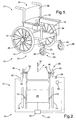
- Figure 1 is a perspective view of the exemplary embodiment of the invention; and
- Figure 2 is a schematic view of a drive system of the exemplary embodiment of the invention.
- The invention provides a
drive system 10 for avehicle 12 and a method for driving avehicle 12. In the exemplary embodiment of the invention, thevehicle 12 is awheel chair 34. Thewheel chair 34 includes aseat portion 36 and aback portion 38 engaged with one another. Thedrive system 10 includes afirst drive wheel 14 rotatable about afirst axis 16 for supporting thevehicle 12 and asecond drive wheel 18 rotatable about thefirst axis 16 for supporting thevehicle 12. The first andsecond drive wheels back portion 38. - The
drive system 10 also includes at least onecastor 20 rotatable about asecond axis 22 transverse to thefirst axis 16. Thesecond axis 22 is defined by arod 22. Thecastor 20 includes asecond rod 46 extending transverse to and rotatably engaged with therod 22. Thecastor 20 also includes awheel 48 rotably disposed on thesecond rod 46. Theexemplary vehicle 12 also includes asecond castor 42 substantially similar to thefirst castor 20, being rotatable about athird axis 44 transverse to thefirst axis 16. The first andsecond castors seat portion 36 spaced from theback portion 38. The exemplary first andsecond castors - The first and
second castors second drive wheels vehicle 12. The first andsecond castors second drive wheels second castors second drive wheels - The
drive system 10 also includes acontroller 24 for differentially driving the first andsecond drive wheels castor 20 about thesecond axis 22. Referring now to Figure 2, it has been observed that when the at least onecastor 20 is not aligned with a desired direction oftravel 32, thevehicle 12 will travel transverse to the desired direction oftravel 32 at least initially. This can be problematic when the vehicle is in a relatively narrow space. The intial movement of thevehicle 12 could cause thevehicle 12 to strike and damage an adjacent structure such as a wall and/or could cause thevehicle 12 to become wedged between other structures. In Figure 2, thecastors travel 32. Also, the initial movement of thevehicle 12 because of the misalignment, without the benefit of the invention, is shown in phantom extending transverse to the desired direction oftravel 32. - The exemplary controller includes a
sensor 26 for sensing the position of thefirst castor 20 about thesecond axis 22 and emitting a first signal corresponding to the position. Thesensor 26 can sense the angular position of therods 22 or the position of therod 46 or the position of thewheel 48. The exemplary controller includes asecond sensor 40, substantially similar to thesensor 26, for sensing the position of thesecond castor 42 about thethird axis 44 and emitting a second signal corresponding to the position. - The
exemplary controller 24 also includes amotor 28 operable to differentially rotate the first andsecond drive wheels sensor 26. Themotor 28 can rotate thefirst drive wheel 14 at a first angular velocity, a first angular acceleration, and/or a first angular direction and rotate thesecond drive wheel 18 at a second angular velocity, a second angular acceleration, and/or a second angular direction, wherein any combination of the first and second angular velocities, the first and second angular accelerations, and the first and second angular directions are different from one another. For example, themotor 28 can rotate thefirst wheel 14 at a first angular velocity and rotate thesecond wheel 18 at a second angular velocity different than the first angular velocity. Themotor 28 can control the first andsecond wheels vehicle 12 in the desired direction oftravel 32. - The
exemplary controller 24 also includes aninput device 30 engageable by an operator of thevehicle 12 for communicating a desired direction oftravel 32 for thevehicle 12. In the exemplary embodiment of the invention, theinput device 30 includes a joystick positionable on thewheel chair 34. In alternative embodiments of the invention, theinput device 30 could be remote from thevehicle 12. In other words, thevehicle 12 could be remote controlled. - In operation, the
exemplary controller 24 is operable to engage themotor 28 to deferentially rotate at least one of the first andsecond drive wheels travel 32 and the position of thecastors controller 24 is operable to rotate thefirst drive wheel 14 at a first angular acceleration and rotate thesecond drive wheel 18 at a second angular acceleration in response tocastor 20 being in a first position about thesecond axis 22, wherein the first and second angular accelerations are different from one another in at least one of direction and rate. In another example, thecontroller 24 can rotate thefirst drive wheel 14 at a third angular acceleration and rotate thesecond drive wheel 18 at a fourth angular acceleration in response to the at least one caster being in a second position about thesecond axis 22 different than the first position. The first and third angular accelerations can be different from one another in at least one of direction and rate. Likewise, the second and fourth angular accelerations can different from one another in at least one of direction and rate. - The
exemplary controller 24 includes an electronic control unit (ECU) 50. The ECU 50 communicates with thesensors motor 28, and theinput device 30. Theinput device 30 communicates the desired direction oftravel 32 to theECU 50. Thesensor 26 communicates the position of thecastor 20 about theaxis 22 to theECU 50. The position of thecastor 20 corresponds to the extent of alignment of thecastor 20 with the desired direction oftravel 32. When thecastor 20 is aligned with the desired direction oftravel 32, thewheel 48 is disposed in a plane extending parallel to the desired direction oftravel 32, as shown in solid line in Figure 2. Thesensor 40 communicates the position of thecastor 42 about theaxis 44 to theECU 50. When thecastor 42 is aligned with the desired direction oftravel 32, awheel 52 of thecastor 42 is disposed in a plane extending parallel to the desired direction oftravel 32, as shown in solid line in Figure 2. After theECU 50 has received signals from theinput device 30 and thesensors ECU 50 engages themotor 28 to differential drive thewheels - The
controller 24 controls thewheels vehicle 12 moves in the desired direction oftravel 32 and such that thecastors travel 32. For example, in a first movement, if thecastors travel 32, thevehicle 12 may move at full speed in the desired direction oftravel 32. However, in a second movement, if thecastors travel 32, thewheels second castors travel 32. In the second movement, the operator may perceive that thevehicle 12 does not immediately move at full speed in the desired direction oftravel 12 as in the first movement. However, in both the first and second movements, the operator would perceive thevehicle 12 moving in the desired direction oftravel 32 from the beginning of movement. - While the invention has been described with reference to an exemplary embodiment, it will be understood by those skilled in the art that various changes may be made and equivalents may be substituted for elements thereof without departing from the scope of the invention. In addition, many modifications may be made to adapt a particular situation or material to the teachings of the invention without departing from the essential scope thereof. Therefore, it is intended that the invention not be limited to the particular embodiment disclosed as the best mode contemplated for carrying out this invention, but that the invention will include all embodiments falling within the scope of the appended claims.
Claims (20)
- A drive system (10) for a vehicle (12) comprising:a first drive wheel (14) rotatable about a first axis (16) for supporting the vehicle (12);a second drive wheel (18) rotatable about said first axis (16) for supporting the vehicle (12);at least one castor (20) rotatable about a second axis (22) transverse to said first axis (16) and forward of said first and second drive wheels (14, 18) in a direction of travel of the vehicle (12); anda controller (24) for differentially driving said first and second drive wheels (14, 18) in response to a position of said at least one castor (20) about said second axis (22).
- The drive system (10) of claim 1 wherein said controller (24) further comprises:a sensor (26) for sensing the position of said at least one castor (20) about said second axis (22) and emitting a signal corresponding to the position.
- The drive system (10) of claim 2 wherein said controller (24) further comprises:a motor (28) operable to differentially rotate said first and second drive wheels (14, 18) in response to signal emitted by the sensor (26).
- The drive system (10) of claim 3 wherein said controller (24) further comprises:an input device (30) engageable by an operator of the vehicle (12) for communicating a desired direction of travel (32) for the vehicle (12).
- The drive system (10) of claim 4 wherein said controller (24) is further defined as being operable to engage the motor (28) to deferentially rotate at least one of said first and second drive wheels (14, 18) in response to an extent of alignment between the desired direction of travel (32) and the position of the at least one castor (20).
- The drive system (10) of claim 1 wherein the vehicle (12) is further defined as a wheel chair (34).
- The drive system (10) of claim 1 wherein said controller (24) is further defined as being operable to rotate said first drive wheel (14) at a first angular acceleration and rotate said second drive wheel (18) at a second angular acceleration in response to said at least one caster being in a first position about said second axis (22), wherein said first and second angular accelerations are different from one another in at least one of direction and rate.
- The drive system (10) of claim 7 wherein said controller (24) is further defined as being operable to rotate said first drive wheel (14) at a third angular acceleration and rotate said second drive wheel (18) at a fourth angular acceleration in response to said at least one caster being in a second position about said second axis (22) different than said first position, wherein said first and third angular accelerations are different from one another in at least one of direction and rate and wherein said second and fourth angular accelerations are different from one another in at least one of direction and rate.
- A method for driving a vehicle (12) comprising the steps of:supporting the vehicle (12) with a first drive wheel (14) rotatable about a first axis (16);supporting the vehicle (12) with a second drive wheel (18) rotatable about the first axis (16);disposing at least one castor (20) rotatable about a second axis (22) transverse to the first axis (16) and forward of the first and second drive wheels (14, 18) in a direction of travel of the vehicle (12); anddifferentially driving the first and second drive wheels (14, 18) in response to a position of the at least one castor (20) about the second axis (22) with a controller (24).
- The method of claim 9 further comprising the step of:determining a desired direction of travel (32) before said differentially driving step.
- The method of claim 10 further comprising the step of:sensing an extent of alignment between the at least one castor (20) and the desired direction of travel (32) before said differentially driving step.
- The method of claim 11 said differentially driving step further comprises the step of:moving the wheels to concurrently travel in the desired direction of travel (32) as well as align the at least one castor (20) with the desired direction of travel (32).
- A drive system (10) for a vehicle (12) comprising:a first drive wheel (14) rotatable about a first axis (16) for supporting the vehicle (12);a second drive wheel (18) rotatable about said first axis (16) for supporting the vehicle (12);a first castor (20) rotatable about a second axis (22) transverse to said first axis (16) and forward of said first and second drive wheels (14, 18) in a direction of travel of the vehicle (12);a second castor (42) rotatable about a third axis (44) transverse to said first axis (16) and forward of said first and second drive wheels (14, 18) in a direction of travel of the vehicle (12); anda controller (24) for differentially driving said first and second drive wheels (14, 18) in response to the positions of said first and second castors (20, 42) about said second and third axis (22, 44), respectively.
- The drive system (10) of claim 13 further comprising:a chair (34) having a seat portion (36) and a back portion (38) and being supported for movement by said first and second drive wheels (14, 18) and said first and second castors (20, 42), wherein said first and second drive wheels (14, 18) are disposed on opposite sides of said back portion (38) and said first and second castors (20, 42) are disposed on opposite sides of said seat portion (36) spaced from said back portion (38).
- The drive system (10) of claim 14 further comprising:a first sensor (26) for sensing the position of said first castor (20) about said second axis (22) and emitting a first signal corresponding to the position.
- The drive system (10) of claim 15 further comprising:a second sensor (40) for sensing the position of said second castor (42) about said third axis (44) and emitting a second signal corresponding to the position.
- The drive system (10) of claim 16 further comprising:an input device (30) engageable by an operator of the vehicle (12) for communicating a desired direction of travel (32) for the vehicle (12), wherein said controller (24) receives said first and second signals and communicates with said input device (30) before moving said first and second drive wheels (14, 18).
- The drive system (10) of claim 17 wherein said controller (24) moves said first and second wheels to align said first and second castors (20, 42) with the desired direction of travel (32).
- The drive system (10) of claim 18 wherein first movement of said first and second wheels to move said chair (34) in the desired direction of travel (32) when said first and second castors (20, 42) are aligned with the desired direction of travel (32) is different than second movement of said first and second wheels to move said chair (34) in the desired direction of travel (32) when said first and second castors (20, 42) are misaligned with the desired direction of travel (32), wherein said chair (34) moves in the desired direction of travel (32) during said first and second movements.
- The drive system (10) of claim 19 wherein said first and second castors (20, 42) are unbiased.
Applications Claiming Priority (1)
| Application Number | Priority Date | Filing Date | Title |
|---|---|---|---|
| US11/220,922 US20070051541A1 (en) | 2005-09-07 | 2005-09-07 | Method of castor management |
Publications (1)
| Publication Number | Publication Date |
|---|---|
| EP1762464A1 true EP1762464A1 (en) | 2007-03-14 |
Family
ID=37450878
Family Applications (1)
| Application Number | Title | Priority Date | Filing Date |
|---|---|---|---|
| EP06076624A Withdrawn EP1762464A1 (en) | 2005-09-07 | 2006-08-28 | Method of castor management |
Country Status (4)
| Country | Link |
|---|---|
| US (1) | US20070051541A1 (en) |
| EP (1) | EP1762464A1 (en) |
| JP (1) | JP2007068980A (en) |
| CA (1) | CA2550269A1 (en) |
Cited By (1)
| Publication number | Priority date | Publication date | Assignee | Title |
|---|---|---|---|---|
| US10864127B1 (en) | 2017-05-09 | 2020-12-15 | Pride Mobility Products Corporation | System and method for correcting steering of a vehicle |
Families Citing this family (2)
| Publication number | Priority date | Publication date | Assignee | Title |
|---|---|---|---|---|
| JP6115775B2 (en) * | 2013-07-26 | 2017-04-19 | アイシン精機株式会社 | Personal vehicle |
| US20240385619A1 (en) * | 2023-05-17 | 2024-11-21 | Scythe Robotics, Inc. | Motion planning with caster constraints |
Citations (2)
| Publication number | Priority date | Publication date | Assignee | Title |
|---|---|---|---|---|
| US4549624A (en) * | 1984-10-12 | 1985-10-29 | Everest & Jennings, Inc. | Wheelchair direction control means |
| EP1591094A1 (en) * | 2004-04-27 | 2005-11-02 | Sunrise Medical HHG Inc. | Wheelchair with drive wheels responsive to operational characteristics of casters |
Family Cites Families (9)
| Publication number | Priority date | Publication date | Assignee | Title |
|---|---|---|---|---|
| US4483405A (en) * | 1981-08-05 | 1984-11-20 | Koyu Enterprise, Inc. | Omnidirectional motorized wheelchair |
| DE3724161C1 (en) * | 1987-07-22 | 1988-12-01 | Meyra Wilhelm Meyer Gmbh & Co | wheelchair |
| DE3832125A1 (en) * | 1988-01-12 | 1989-07-20 | Ortopedia Gmbh | ELECTRIC WHEELCHAIR |
| US5547038A (en) * | 1991-08-01 | 1996-08-20 | Madwed; Albert | Wheeled chassis having independently pivotable drivewheels for omnidirectional motion |
| US5322140A (en) * | 1992-02-03 | 1994-06-21 | Amigo Mobility International, Inc. | Steering systems for four-wheeled carts |
| US5487437A (en) * | 1994-03-07 | 1996-01-30 | Avitan; Isaac | Coupled differential turning control system for electric vehicle traction motors |
| GB9423056D0 (en) * | 1994-11-16 | 1995-01-04 | Sunrise Medical Ltd | Castors, and vehicles having same |
| NL9402006A (en) * | 1994-11-29 | 1996-07-01 | Seenus Nl Bv R Van | Wheelchair frame, as well as castor assembly. |
| NL1003396C1 (en) * | 1996-06-21 | 1997-12-23 | Ligtvoet Products Bv | Wheelchair equipped with a castor wheel. |
-
2005
- 2005-09-07 US US11/220,922 patent/US20070051541A1/en not_active Abandoned
-
2006
- 2006-06-12 CA CA002550269A patent/CA2550269A1/en not_active Abandoned
- 2006-07-27 JP JP2006204075A patent/JP2007068980A/en active Pending
- 2006-08-28 EP EP06076624A patent/EP1762464A1/en not_active Withdrawn
Patent Citations (2)
| Publication number | Priority date | Publication date | Assignee | Title |
|---|---|---|---|---|
| US4549624A (en) * | 1984-10-12 | 1985-10-29 | Everest & Jennings, Inc. | Wheelchair direction control means |
| EP1591094A1 (en) * | 2004-04-27 | 2005-11-02 | Sunrise Medical HHG Inc. | Wheelchair with drive wheels responsive to operational characteristics of casters |
Cited By (1)
| Publication number | Priority date | Publication date | Assignee | Title |
|---|---|---|---|---|
| US10864127B1 (en) | 2017-05-09 | 2020-12-15 | Pride Mobility Products Corporation | System and method for correcting steering of a vehicle |
Also Published As
| Publication number | Publication date |
|---|---|
| JP2007068980A (en) | 2007-03-22 |
| CA2550269A1 (en) | 2007-03-07 |
| US20070051541A1 (en) | 2007-03-08 |
Similar Documents
| Publication | Publication Date | Title |
|---|---|---|
| EP1591092A2 (en) | Power wheelchair | |
| US9233671B2 (en) | Parking lock control device for vehicle and control method | |
| US20190009815A1 (en) | Enhanced yaw rate trailer angle detection initialization | |
| US9216719B2 (en) | Parking lock control device for vehicle and control method | |
| JP2001199356A (en) | Omnidirectional vehicle and its control method | |
| JPH10194143A (en) | Electric power steering device | |
| CA2503103C (en) | Transport with rotatable load and safety bumper | |
| CA2475639A1 (en) | Pallet truck tiller arm with angle detector for speed select | |
| EP2058216A1 (en) | Traveling vehicle | |
| CN105667578A (en) | Steering device, automobile steering control system and automobile | |
| US11364893B2 (en) | Autonomous driving system and autonomous steering apparatus | |
| US20140032073A1 (en) | Parking lock control device for vehicle and control method | |
| US20070051541A1 (en) | Method of castor management | |
| JPH09164968A (en) | Omnidirectional vehicle and control method thereof | |
| WO2009113725A1 (en) | Travel mode switching control system for automated guided vehicle and switching control method | |
| JPH02189283A (en) | Steering apparatus for rear wheel for automobile | |
| KR20140100324A (en) | Steering system | |
| JP2007048157A (en) | Travel control device for automatic guided vehicle | |
| US20220355855A1 (en) | System for a Vehicle that Compensates for Vehicle Spin | |
| JP2000127776A (en) | Omnidirectional vehicle and drive mechanism control method thereof | |
| JP2009083759A (en) | vehicle | |
| JP3374387B2 (en) | Unmanned car | |
| JP2020165464A (en) | Electric actuator and actuator device | |
| EP1591094A1 (en) | Wheelchair with drive wheels responsive to operational characteristics of casters | |
| JP3735716B2 (en) | Tracking control system for linked self-propelled vehicles |
Legal Events
| Date | Code | Title | Description |
|---|---|---|---|
| PUAI | Public reference made under article 153(3) epc to a published international application that has entered the european phase |
Free format text: ORIGINAL CODE: 0009012 |
|
| AK | Designated contracting states |
Kind code of ref document: A1 Designated state(s): AT BE BG CH CY CZ DE DK EE ES FI FR GB GR HU IE IS IT LI LT LU LV MC NL PL PT RO SE SI SK TR |
|
| AX | Request for extension of the european patent |
Extension state: AL BA HR MK YU |
|
| 17P | Request for examination filed |
Effective date: 20070914 |
|
| 17Q | First examination report despatched |
Effective date: 20071019 |
|
| AKX | Designation fees paid |
Designated state(s): AT BE BG CH CY CZ DE DK EE ES FI FR GB GR HU IE IS IT LI LT LU LV MC NL PL PT RO SE SI SK TR |
|
| STAA | Information on the status of an ep patent application or granted ep patent |
Free format text: STATUS: THE APPLICATION IS DEEMED TO BE WITHDRAWN |
|
| 18D | Application deemed to be withdrawn |
Effective date: 20080430 |