EP1762463A1 - Steering boot - Google Patents
Steering boot Download PDFInfo
- Publication number
- EP1762463A1 EP1762463A1 EP05019396A EP05019396A EP1762463A1 EP 1762463 A1 EP1762463 A1 EP 1762463A1 EP 05019396 A EP05019396 A EP 05019396A EP 05019396 A EP05019396 A EP 05019396A EP 1762463 A1 EP1762463 A1 EP 1762463A1
- Authority
- EP
- European Patent Office
- Prior art keywords
- steering
- attachment part
- bellows
- ball joint
- outer peripheral
- Prior art date
- Legal status (The legal status is an assumption and is not a legal conclusion. Google has not performed a legal analysis and makes no representation as to the accuracy of the status listed.)
- Granted
Links
- 230000002093 peripheral effect Effects 0.000 claims abstract description 29
- 238000005452 bending Methods 0.000 abstract description 10
- 230000010355 oscillation Effects 0.000 abstract description 5
- 239000002184 metal Substances 0.000 description 6
- 238000007789 sealing Methods 0.000 description 6
- 230000006835 compression Effects 0.000 description 3
- 238000007906 compression Methods 0.000 description 3
- 239000000428 dust Substances 0.000 description 3
- 229920005992 thermoplastic resin Polymers 0.000 description 3
- XLYOFNOQVPJJNP-UHFFFAOYSA-N water Substances O XLYOFNOQVPJJNP-UHFFFAOYSA-N 0.000 description 3
- 230000002159 abnormal effect Effects 0.000 description 2
- 230000008878 coupling Effects 0.000 description 2
- 238000010168 coupling process Methods 0.000 description 2
- 238000005859 coupling reaction Methods 0.000 description 2
- 238000006073 displacement reaction Methods 0.000 description 2
- 230000001105 regulatory effect Effects 0.000 description 2
- 238000005096 rolling process Methods 0.000 description 2
- ZPUCINDJVBIVPJ-LJISPDSOSA-N cocaine Chemical compound O([C@H]1C[C@@H]2CC[C@@H](N2C)[C@H]1C(=O)OC)C(=O)C1=CC=CC=C1 ZPUCINDJVBIVPJ-LJISPDSOSA-N 0.000 description 1
- 230000000694 effects Effects 0.000 description 1
- 239000004519 grease Substances 0.000 description 1
Images

Classifications
-
- F—MECHANICAL ENGINEERING; LIGHTING; HEATING; WEAPONS; BLASTING
- F16—ENGINEERING ELEMENTS AND UNITS; GENERAL MEASURES FOR PRODUCING AND MAINTAINING EFFECTIVE FUNCTIONING OF MACHINES OR INSTALLATIONS; THERMAL INSULATION IN GENERAL
- F16D—COUPLINGS FOR TRANSMITTING ROTATION; CLUTCHES; BRAKES
- F16D3/00—Yielding couplings, i.e. with means permitting movement between the connected parts during the drive
- F16D3/84—Shrouds, e.g. casings, covers; Sealing means specially adapted therefor
- F16D3/843—Shrouds, e.g. casings, covers; Sealing means specially adapted therefor enclosed covers
- F16D3/845—Shrouds, e.g. casings, covers; Sealing means specially adapted therefor enclosed covers allowing relative movement of joint parts due to the flexing of the cover
-
- B—PERFORMING OPERATIONS; TRANSPORTING
- B62—LAND VEHICLES FOR TRAVELLING OTHERWISE THAN ON RAILS
- B62D—MOTOR VEHICLES; TRAILERS
- B62D3/00—Steering gears
- B62D3/02—Steering gears mechanical
- B62D3/12—Steering gears mechanical of rack-and-pinion type
Definitions
- the present invention relates to a steering boot covering a coupling portion between a steering rack and a tie rod in a motor vehicle.
- a rack-and-pinion steering apparatus of a motor vehicle is structured as well known such that a steering rack is moved via a pinion gear on the basis of a rotational operation of a steering wheel by a driver, and tie rods coupled to both right and left ends thereof via a ball joint are oscillated with respect to a steering rack, thereby swiveling a tire wheel in an optional direction.
- the coupling portion between both the end portions of the steering rack and the tie rod is covered by a steering boot in such a manner as to prevent a muddy water, a dust or the like from making an intrusion into a ball joint portion or prevent a grease from flowing out.
- a steering boot As a typical prior art of this kind of steering boot, there is a structure disclosed in Japanese Unexamined Patent Publication No. 61-109967 .
- the steering boot is formed in a bellows shape in which annular crest parts and trough parts are alternately formed, by a thermoplastic resin, in such a manner as to follow to a reciprocating motion in an axial direction of the steering rack and an oscillating motion of the tie rod.
- a thermoplastic resin in such a manner as to follow to a reciprocating motion in an axial direction of the steering rack and an oscillating motion of the tie rod.
- FIG. 8 is an explanatory view showing a deformed state of the conventional steering boot.
- Reference numeral 101 in the drawing denotes a steering boot
- reference numeral 102 denotes a steering rack
- reference numeral 103 denotes a tie rod coupled to the steering rack 102 via a ball joint 104
- reference numeral 105 denotes a rack housing supporting the steering rack 102 so as to be slidable in axial direction.
- a large-diameter side end portion 101a of the steering boot 101 is outside inserted and fixed to an outer peripheral surface of the rack housing 105 in a sealing manner, and a small-diameter side end portion 101b is outside inserted and fixed to an outer peripheral surface of the tie rod 103 in a sealing manner.
- the present invention is made by taking the points mentioned above into consideration, and a technical object of the present invention is to provide a steering boot having no risk that the steering boot exposed to a high temperature atmosphere is broken because a trough part is caught on a socket of a ball joint at a time when a bellows part is exposed to a bending deformation on the basis of an oscillation of a tie rod.
- a steering boot comprising:
- the steering toot is relatively compressed in a portion forming an outer peripheral side of the ball joint on the basis of an increase of an internal pressure, and is relatively expanded in the other portions. Accordingly, since a bending deformation of the bellows portion following to the oscillation of the tie rod around the ball joint is mainly increased in the outer peripheral side of the ball joint, and an inner periphery of a portion displacing to an axis of the steering rack while contracting on the basis of the bending is positioned in the outer periphery of the ball joint, the catch on the end portion of the ball joint is not generated.
- the steering boot of the first aspect wherein the outer diameter of the crest part and the inner diameter of the trough part become gradually smaller from the end part on the first attachment part side to the end part of the second attachment part side.
- the pressure receiving diameter at a time when the internal pressure is increased is relatively larger toward the position close to the end portion of the first attachment part side in which the outer diameter of the crest part and the inner diameter of the trough part are large, and the pressure receiving diameter at a time when the internal pressure is increased becomes relatively smaller toward the position close to the end portion in the second attachment part side, the expanding force of the steering boot on the basis of the increase of the internal pressure becomes relatively larger in the first attachment part side (the rack housing side), and becomes relatively smaller in the second attachment part side (the tie rod side).
- the bellows part of the steering boot is expanded in the first attachment part side, and is contracted in the second attachment part side, the movement in the diametrical direction is inhibited in the portion close to the first attachment part on the basis of the expansion, and the catch on the end portion of the ball joint is not generated.
- the steering boot of the second aspect wherein the inclination angle of a conical face passing through an arbitrary crest part and the crest part adjacent to the smaller diameter side thereof or a conical face passing through an arbitrary trough and a trough adjacent to the smaller diameter side thereof in respect to the axial center is made equal or inferior to 30 degrees.
- the angle ⁇ is defined to be equal or inferior to 30 degrees because the torsional stress of the steering boot becomes too large at a time when the tie rod is twisted for regulating the toe-in angle of the tire wheel if the angle is more than 30 degrees, so that the durability is lowered.
- the catch on the end portion of the ball joint is not generated at the deforming time following to the oscillation of the tie rod, it is possible to prevent an abnormal noise and a vibration from being generated, and it is possible to prevent the steering boot from being bored and broken.
- the bellows part is expanded in the first attachment part side and is contracted in the second attachment part side at a time when the internal pressure is increased, the movement in the diametrical direction is inhibited in the portion close to the first attachment part on the basis of the expansion, and it is possible to further effectively prevent the catch on the end portion of the ball joint.
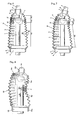
- Fig. 1 is an explanatory view showing a relation between a cross section of a loaded state and a thickness and showing a steering boot in accordance with a first aspect of the present invention
- Fig. 2 is an explanatory view showing a deforming state of a thin crest part on the basis of an internal pressure in the aspect in Fig. 1
- Fig. 3 is a cross sectional view showing a loaded state and a bending state of the steering boot in accordance with the aspect in Fig. 1.
- reference numeral 1 denotes a steering rack reciprocated in an axial direction via a pinion gear on the basis of a rotational operation of a steering wheel (not shown)
- reference numeral 2 denotes a rack housing through which the steering rack 1 is inserted
- reference numeral 3 denotes a tie rod coupled to an end portion (both ends) of the steering rack 1 via a ball joint 4.
- the ball joint 4 is constituted by a ball part 41 firmed in an end portion of the tie rod 3, and a socket 42 formed in an end portion of the steering rack 1 and holding the ball part 41 so as to freely roll.
- a steering boot 10 in accordance with this aspect is formed by a thermoplastic resin, and is provided with a bellows part 11 in which annular crest parts 111 and trough parts 112 are alternately formed, a first attachment part 12 formed in one end of the bellows part 11, fastened to an outer peripheral surface of the rack housing 2 by a metal band 5 and fixed in an sealing manner, and a second attachment part 13 formed in the other end of the bellows part 11, fastened to an outer peripheral surface of the tie rod 3 by a metal band 6 and fixed to a sealing manner.
- the 10 surrounds so as to seal a portion from the rack housing 2 to a portion near an end portion of the tie rod 3 via an outer periphery of a joint portion between the steering rack 1 and the tie rod 3 by the ball joint 4.
- the bellows part 11 is structured such that an outer diameter of each of the crest parts 111 and an inner diameter of each of the trough parts 112 are uniform with each other in a region except the first to third stages of crest parts 111a to 111c and the first to third stages of trough parts 112a to 112c from the second attachment part 13 side, and accordingly in this region, a rolling height h of the crest part 111 and the trough part 112 is uniform.
- a rolling height h of the crest part 111 and the trough part 112 is uniform.
- the first to third stages of crest parts 111a to 111c and the first to third stages of trough parts 112a to 112c are formed so as to be gradually smaller in diameter such that the first stage forms the smallest diameter.
- a thickness t of the bellows part 11 is relatively thinner than the other portions in the portion 11A forming the outer peripheral side of the ball joint 4.
- the thickness t of the bellows part 11 is changed such that the thickness t becomes smallest (tA) in the portion 11A forming the outer peripheral side of the ball joint 4, and becomes gradually thicker toward the first attachment part 12 side in the portion 11B closer to the first attachment part 12 side than the portion 11A, and the thickness t is changed such that the thickness becomes gradually thicker toward the second attachment part 13 side in the portion 11C closer to the second attachment part 13 side than the portion 11A.
- a thickness tB in an end portion of the first attachment part 12 side is larger than a thickness tC in an end portion of the second attachment part 13 side.
- end walls 14 and 15 corresponding to both ends in an axial direction of the bellows part 11 respectively have a plurality of ribs 14a and 15a in a circumferential direction, thereby being reinforced.
- the steering boot 10 seals a portion from the rack housing 2 to the portion near ten end portion of the tie rod 3 via an outer periphery of a joint portion between the steering rack 1 and the tie rod 3 by the ball joint 4, thereby protecting the ball joint 4 and the periphery thereof from a muddy water and a dust.
- an internal pressure of the steering boot 10 becomes higher on the basis of an expansion of an air within the steering boot 10.
- the internal pressure uniformly applies to all the portions in the inner surface of the bellows part 11, however, the internal pressure is applied in the portion in which the thickness t is large in such a manner as to open each of the crest parts 111 in the axial direction, however, if the internal pressure P is applied to the portion in which the thickness t is small, as shown in Fig.
- the bellows part 11 in the steering boot 10 is deformed as shown in Fig. 3 between the first attachment part 12 fixed to the rack housing 2 and the second attachment part 13 displacing together with the tie rod 3.
- the bellows part 11 is largely bent in the portion 11A in which the thickness t becomes thinnest, in the outer peripheral side of the ball joint 4.
- the thinnest portion 11A in the bellows part 11 is largely exposed to the compression in an inner side of the bending. Further, an inner periphery in the compression side in the thin portion 11A is close to or brought into contact with the outer peripheral surface of the socket 42 of the ball joint 4 accompanying with the deformation mentioned above, and the portion 11B in the first attachment part 12 side is inhibited from being displaced in the diametrical direction due to the relatively large expanding force in the axial direction. Accordingly, there is no risk that the portion 11B closer to the first attachment part 12 side than the ball joint 4 enters into the inner peripheral side from the socket 42 so as to be caught on the corner portion 42a.
- the internal pressure of the steering boot 10 is applied so as to get down the end walls 14 and 15 in both ends in the axial direction to the outer side, however, since the end walls 14 and 15 are formed thicker than the bellows part 11, and is reinforced by ribs 14a and 15a, it is possible to prevent the end walls 14 and 15 from getting down due to the internal pressure so as to be damaged by the interference of the metal bands 5 and 6 with a thread portion (not shown) or the like.
- FIG. 4 is a cross sectional view of an unloaded state showing a steering boot in accordance with a second aspect of the present invention
- Fig. 5 is a partly enlarged cross sectional view of the steering boot in accordance with the aspect in Fig. 4
- Fig. 6 is a cross sectional view showing an internal pressure applying state in a loaded state of the steering boot in accordance with the aspect in Fig. 4
- Fig. 7 is a cross sectional view showing the internal pressure applying state and a bending state in the loaded state of the steering boot in accordance with the aspect in Fig. 4.
- the steering boot 10 in accordance with this aspect is formed by a thermoplastic resin, and is provided, as shown in Fig. 4, with the bellows part 11 in which the annular crest part 111 and the trough part 112 are alternately formed, the first attachment part 12 formed in one end of the bellows part 11, and the second attachment part 13 formed in the other end of the bellows 11.
- This aspect is different from the previously described first aspect in a point that an outer diameter of the crest part 111 in the bellows part 11 and an inner diameter of the trough part 112 are gradually smaller from the end portion in the first attachment part 12 side toward the end portion in the second attachment part 13 side.
- an angle ⁇ of incline which a conical surface passing through an outer diameter of an n stage of crest part 111 n and an outer diameter of an (n-1) stage of crest part 111 n-1 adjacent in a small-diameter side forms with respect to an axis is set to be equal to or less than 30 degrees.
- the values a and x are defined in such a manner that a formula tan -1 (a/x) is between 0 and 30 degrees.
- a rolling height h between the crest part 111 and the trough part 112 is uniform, and accordingly, the trough part has the same relation as the crest part 111.
- the thickness t of the bellows part 11 is distributed in the same manner as the graph in the previously explained Fig. 1, that is, the thickness t is changed such that the thickness t becomes thinnest in the portion 11A forming the outer peripheral side of the ball joint, and becomes gradually thicker toward the first attachment part 12 side in the portion 11B closer to the first attachment part 12 side than the portion 11A, and the thickness t is changed such that the thickness becomes gradually thicker toward the second attachment part 13 side in the portion 11C closer to the second attachment part 13 side than the portion 11A. Further, a thickness in an end portion of the first attachment part 12 side is larger than a thickness in an end portion of the second attachment part 13 side.
- the first attachment part 12 of the steering boot 10 having the structure mentioned above is fastened to the outer peripheral surface of the rack housing 2 by the metal band 5, whereby the steering boot 10 is fixed in a sealing manner, as shown in Fig. 6, and the second attachment part 13 is fastened to the outer peripheral surface of the tie rod 3 by the metal band 6, whereby the steering boot 10 is fixed in a sealing manner.
- the bellows part 11 surrounds the portion from the rack housing 2 to the outer peripheral side of the joint portion between the steering rack 1 and the tie rod 3 by the ball joint 4 and the portion reaching the end portion of the tie rod 3, thereby protecting the ball joint 4 and the periphery thereof from the muddy water and the dust.
- the internal pressure of the steering boot 10 becomes higher on the basis of the expansion of the air.
- the internal pressure is uniformly applied to the inner surface of the bellows part 11. Further, since a pressure receiving area receiving the internal pressure is larger toward the large-diameter side (the first attachment part 12 side) of the bellows part 11, the expanding force in the axial direction on the basis of the internal pressure is larger toward the position close to the first attachment part 12, and the expanding force in the axial direction on the basis of the internal pressure becomes smaller toward the position close to the second attachment part 13 forming the smaller diameter.
- the bellows part 11 is relatively expanded in the first attachment part 12 side, and is relatively compressed in the portion close to the second attachment part 13. Further, since the portion 11C closest to the second attachment part 13 is gradually thicker toward the second attachment part 13 side, the bellows part 11 is most compressed in the portion 11A positioned in the outer periphery of the ball joint 4.
- the thickness distribution of the bellows part 11 is the same as Fig. 1, whereby the thinnest portion 11A is relatively compressed, whereby the bellows part 11 is relatively expanded in the other thicker portions 11B and 11C than the thinnest portion 11A.
- the bellows part 11 of the steering boot 10 is deformed as shown in Fig. 7 between the first attachment part 12 fixed to the rack housing 2 and the second attachment part 13 displacing together with the tie rod 3.
- the bellows part 11 is largely bent in the portion 11A in which the thickness t becomes thinnest, in the outer peripheral side of the ball joint 4, and the compression side inner periphery of this portion 11A is close to or brought into contact with the outer peripheral surface of the socket 42 of the ball joint 4.
- the portion 11B in the first attachment part 12 side is larger in the expanding force in the axial direction toward the large-diameter side on the basis of the internal pressure, the displacement in the diametrical direction is inhibited. Accordingly, it is possible to effectively prevent the portion 11B in the first attachment part 12 side from the ball joint 4 from entering into the inner peripheral side from the socket 42 so as to be caught on the corner portion 42a of the socket 42 of the ball joint 4.
- the angle ⁇ of incline which the conical surface passing through the outer diameter of the crest part 111 forms with respect to the axis is set to be gentle equal to or less than 30 degrees, it is possible to restrict the torsional stress applied to the steering boot 10 even in the case that the tie rod 3 is twisted for regulating the toe-in angle of the tire wheel (not shown), and an excellent durability can be secured.
- end walls 14 and 15 in both sides in the axial direction of the bellows part 11 are thicker than the bellows part 11 as in the same manner as the first aspect, and are reinforced by the ribs 14a and 15a, it is possible to prevent the end walls 14 and 15 from getting down due to the internal pressure so as to be damaged by the interference with the thread portions (not shown) of the metal bands 5 and 6 or the like.
Landscapes
- Engineering & Computer Science (AREA)
- General Engineering & Computer Science (AREA)
- Mechanical Engineering (AREA)
- Chemical & Material Sciences (AREA)
- Combustion & Propulsion (AREA)
- Transportation (AREA)
- Pivots And Pivotal Connections (AREA)
- Diaphragms And Bellows (AREA)
- Materials For Medical Uses (AREA)
- Diaphragms For Electromechanical Transducers (AREA)
- Sealing Devices (AREA)
- Steering-Linkage Mechanisms And Four-Wheel Steering (AREA)
Abstract
Description
- The present invention relates to a steering boot covering a coupling portion between a steering rack and a tie rod in a motor vehicle.
- A rack-and-pinion steering apparatus of a motor vehicle is structured as well known such that a steering rack is moved via a pinion gear on the basis of a rotational operation of a steering wheel by a driver, and tie rods coupled to both right and left ends thereof via a ball joint are oscillated with respect to a steering rack, thereby swiveling a tire wheel in an optional direction.
- The coupling portion between both the end portions of the steering rack and the tie rod is covered by a steering boot in such a manner as to prevent a muddy water, a dust or the like from making an intrusion into a ball joint portion or prevent a grease from flowing out. As a typical prior art of this kind of steering boot, there is a structure disclosed in
Japanese Unexamined Patent Publication No. 61-109967 - The steering boot is formed in a bellows shape in which annular crest parts and trough parts are alternately formed, by a thermoplastic resin, in such a manner as to follow to a reciprocating motion in an axial direction of the steering rack and an oscillating motion of the tie rod. Further, in accordance with the prior art, as described in
Japanese Unexamined Patent Publication No. 61-109967 - However, in accordance with the conventional steering boot, particularly in use under a high temperature environment, there is a case that a part of the expanded and contracted steering boot is caught on a socket portion of the ball joint at a time of the reciprocating motion of the steering rack and the oscillating motion of the tie rod. Fig. 8 is an explanatory view showing a deformed state of the conventional steering boot.
Reference numeral 101 in the drawing denotes a steering boot,reference numeral 102 denotes a steering rack, reference numeral 103 denotes a tie rod coupled to thesteering rack 102 via aball joint 104, andreference numeral 105 denotes a rack housing supporting thesteering rack 102 so as to be slidable in axial direction. A large-diameterside end portion 101a of thesteering boot 101 is outside inserted and fixed to an outer peripheral surface of therack housing 105 in a sealing manner, and a small-diameter side end portion 101b is outside inserted and fixed to an outer peripheral surface of the tie rod 103 in a sealing manner. - Further, since all of radii of the chevrons and the valleys of the
steering boot 101 are equal, if an internal pressure is increased under a high temperature environment on the basis of a volume expansion of an air closed in an inner periphery of thesteering boot 101, thesteering boot 101 is exposed to a bending deformation as shown in Fig. 8 at a time of the following motion to the displacement in the axial direction of thesteering rack 102 and the oscillation of the tie rod 103 in accordance therewith. Accordingly, a portion A in which the crest parts and the valley parts are contracted is generated in an intermediate portion in the axial direction, and atrough part 101c in the portion is close to an outer peripheral surface of thesteering rack 102. - Accordingly, if the
steering rack 102 is displaced in the axial direction as shown by an arrow B under this state, asocket 104a of theball joint 104 in an end portion thereof interferes with thetrough part 101c of the contracted portion so as to be caught thereon. Further, there is a risk that a bore is formed in thetrough part 101c of thesteering boot 101 of thesteering boot 101 is broken as well as an abnormal noise is generated due to the catch as mentioned above and a vibration is generated at a time when the catch comes off. - The present invention is made by taking the points mentioned above into consideration, and a technical object of the present invention is to provide a steering boot having no risk that the steering boot exposed to a high temperature atmosphere is broken because a trough part is caught on a socket of a ball joint at a time when a bellows part is exposed to a bending deformation on the basis of an oscillation of a tie rod.
- As a means for effectively solving the technical problem mentioned above, in accordance with a first aspect of the present invention, there is provided a steering boot comprising:
- a bellows part in which annular crest parts and trough parts are formed alternately, a first attachment part formed at one end of the bellows part to be tightly fixed to an outer peripheral surface of a rack housing where a steering rack is inserted through movably in an axial direction, and a second attachment part formed at the other end of the bellows part to be tightly fixed to an outer peripheral surface of a tie rod jointed oscillatably to the steering rack via a ball joint, wherein the bellows part is formed relatively thinner in a portion than in the other portions, on the outer peripheral side of the ball joint.
- In accordance with this structure, the steering toot is relatively compressed in a portion forming an outer peripheral side of the ball joint on the basis of an increase of an internal pressure, and is relatively expanded in the other portions. Accordingly, since a bending deformation of the bellows portion following to the oscillation of the tie rod around the ball joint is mainly increased in the outer peripheral side of the ball joint, and an inner periphery of a portion displacing to an axis of the steering rack while contracting on the basis of the bending is positioned in the outer periphery of the ball joint, the catch on the end portion of the ball joint is not generated.
- Further, in accordance with a second aspect of the present invention, there is provided the steering boot of the first aspect, wherein the outer diameter of the crest part and the inner diameter of the trough part become gradually smaller from the end part on the first attachment part side to the end part of the second attachment part side.
- In accordance with this structure, since the pressure receiving diameter at a time when the internal pressure is increased is relatively larger toward the position close to the end portion of the first attachment part side in which the outer diameter of the crest part and the inner diameter of the trough part are large, and the pressure receiving diameter at a time when the internal pressure is increased becomes relatively smaller toward the position close to the end portion in the second attachment part side, the expanding force of the steering boot on the basis of the increase of the internal pressure becomes relatively larger in the first attachment part side (the rack housing side), and becomes relatively smaller in the second attachment part side (the tie rod side). Accordingly, since the bellows part of the steering boot is expanded in the first attachment part side, and is contracted in the second attachment part side, the movement in the diametrical direction is inhibited in the portion close to the first attachment part on the basis of the expansion, and the catch on the end portion of the ball joint is not generated.
- Further, in accordance with a third aspect of the present invention, there is provided the steering boot of the second aspect, wherein the inclination angle of a conical face passing through an arbitrary crest part and the crest part adjacent to the smaller diameter side thereof or a conical face passing through an arbitrary trough and a trough adjacent to the smaller diameter side thereof in respect to the axial center is made equal or inferior to 30 degrees.
- In this structure, the angle θ is defined to be equal or inferior to 30 degrees because the torsional stress of the steering boot becomes too large at a time when the tie rod is twisted for regulating the toe-in angle of the tire wheel if the angle is more than 30 degrees, so that the durability is lowered.
- In accordance with the steering boot on the basis of the first aspect of the present invention, since the catch on the end portion of the ball joint is not generated at the deforming time following to the oscillation of the tie rod, it is possible to prevent an abnormal noise and a vibration from being generated, and it is possible to prevent the steering boot from being bored and broken.
- In accordance with the steering boot on the basis of the second aspect of the present invention, since the bellows part is expanded in the first attachment part side and is contracted in the second attachment part side at a time when the internal pressure is increased, the movement in the diametrical direction is inhibited in the portion close to the first attachment part on the basis of the expansion, and it is possible to further effectively prevent the catch on the end portion of the ball joint.
- In accordance with the steering boot on the basis of the third aspect of the present invention, since the generation of the torsional stress can be inhibited, an excellent durability can be secured in addition to the effect obtained by the second aspect.
-
- Fig. 1 is an explanatory view showing a relation between a cross section of a loaded state and a thickness and showing a steering boot in accordance with a first aspect of the present invention;
- Fig. 2 is an explanatory view showing a deforming state of a thin crest part on the basis of an internal pressure of a steering boot in accordance with the aspect in Fig. 1;
- Fig. 3 is a cross sectional view showing a loaded state and a bending state of the steering boot in accordance with the aspect in Fig. 1;
- Fig. 4 is a cross sectional view of an unloaded state showing a steering boot in accordance with a second aspect of the present invention;
- Fig. 5 is a partly enlarged cross sectional view of the steering boot in accordance with the aspect in Fig. 4;
- Fig. 6 is a cross sectional view showing an internal pressure applying state in a loaded state of the steering boot in accordance with the aspect in Fig. 4;
- Fig. 7 is a cross sectional view showing the internal pressure applying state and a bending state in the loaded state of the steering boot in accordance with the aspect in Fig. 4; and
- Fig. 8 is an explanatory view showing a deformed state of a conventional steering boot.
- A description will be in detail given below of a preferable embodiment of a steering boot in accordance with the present invention with reference to the accompanying drawings. First, Fig. 1 is an explanatory view showing a relation between a cross section of a loaded state and a thickness and showing a steering boot in accordance with a first aspect of the present invention, Fig. 2 is an explanatory view showing a deforming state of a thin crest part on the basis of an internal pressure in the aspect in Fig. 1, and Fig. 3 is a cross sectional view showing a loaded state and a bending state of the steering boot in accordance with the aspect in Fig. 1.
- First, in Fig. 1,
reference numeral 1 denotes a steering rack reciprocated in an axial direction via a pinion gear on the basis of a rotational operation of a steering wheel (not shown), reference numeral 2 denotes a rack housing through which thesteering rack 1 is inserted, andreference numeral 3 denotes a tie rod coupled to an end portion (both ends) of thesteering rack 1 via a ball joint 4. The ball joint 4 is constituted by aball part 41 firmed in an end portion of thetie rod 3, and asocket 42 formed in an end portion of thesteering rack 1 and holding theball part 41 so as to freely roll. - A
steering boot 10 in accordance with this aspect is formed by a thermoplastic resin, and is provided with abellows part 11 in whichannular crest parts 111 andtrough parts 112 are alternately formed, afirst attachment part 12 formed in one end of thebellows part 11, fastened to an outer peripheral surface of the rack housing 2 by a metal band 5 and fixed in an sealing manner, and asecond attachment part 13 formed in the other end of thebellows part 11, fastened to an outer peripheral surface of thetie rod 3 by a metal band 6 and fixed to a sealing manner. In other words, in a loaded state in Fig. 1, the 10 surrounds so as to seal a portion from the rack housing 2 to a portion near an end portion of thetie rod 3 via an outer periphery of a joint portion between thesteering rack 1 and thetie rod 3 by the ball joint 4. - The
bellows part 11 is structured such that an outer diameter of each of thecrest parts 111 and an inner diameter of each of thetrough parts 112 are uniform with each other in a region except the first to third stages ofcrest parts 111a to 111c and the first to third stages oftrough parts 112a to 112c from thesecond attachment part 13 side, and accordingly in this region, a rolling height h of thecrest part 111 and thetrough part 112 is uniform. In other words, in a state in Fig. 1 in which thesteering rack 1 and thetie rod 3 are arranged on the same axis, an envelope curve passing through each of thecrest parts 111 and an envelope curve passing through each of thetrough parts 112 become in parallel to an axis of thesteering rack 1. The first to third stages ofcrest parts 111a to 111c and the first to third stages oftrough parts 112a to 112c are formed so as to be gradually smaller in diameter such that the first stage forms the smallest diameter. - A thickness t of the
bellows part 11 is relatively thinner than the other portions in theportion 11A forming the outer peripheral side of the ball joint 4. In detail, as a distribution of the thickness t is shown by a graph in Fig. 1, the thickness t of thebellows part 11 is changed such that the thickness t becomes smallest (tA) in theportion 11A forming the outer peripheral side of the ball joint 4, and becomes gradually thicker toward thefirst attachment part 12 side in the portion 11B closer to thefirst attachment part 12 side than theportion 11A, and the thickness t is changed such that the thickness becomes gradually thicker toward thesecond attachment part 13 side in theportion 11C closer to thesecond attachment part 13 side than theportion 11A. Further, a thickness tB in an end portion of thefirst attachment part 12 side is larger than a thickness tC in an end portion of thesecond attachment part 13 side. - Further,
end walls bellows part 11 respectively have a plurality ofribs - In the structure mentioned above, the steering boot 10 seals a portion from the rack housing 2 to the portion near ten end portion of the
tie rod 3 via an outer periphery of a joint portion between thesteering rack 1 and thetie rod 3 by the ball joint 4, thereby protecting the ball joint 4 and the periphery thereof from a muddy water and a dust. - In this case, if a high temperature atmosphere is formed by a radiant heat from a road surface or the like, an internal pressure of the
steering boot 10 becomes higher on the basis of an expansion of an air within thesteering boot 10. The internal pressure uniformly applies to all the portions in the inner surface of thebellows part 11, however, the internal pressure is applied in the portion in which the thickness t is large in such a manner as to open each of thecrest parts 111 in the axial direction, however, if the internal pressure P is applied to the portion in which the thickness t is small, as shown in Fig. 2, a portion close to the outer periphery bulges on the basis of the deflection of the wall surface of thecrest part 111, and thetrough part 112 side is deformed inversely such that an angle becomes smaller. Accordingly, theportion 11A positioned in the outer periphery of the ball joint 4 is relatively compressed due to the smallest thickness tA, and the otherthicker portions 11B and 11C are relatively expanded. - Further, if a driver of a vehicle turns the steering wheel, whereby the
tie rod 3 is angularly displaced around theball part 41 of the ball joint 4 while thesteering rack 1 moves in the axial direction, thebellows part 11 in thesteering boot 10 is deformed as shown in Fig. 3 between thefirst attachment part 12 fixed to the rack housing 2 and thesecond attachment part 13 displacing together with thetie rod 3. In other words, thebellows part 11 is largely bent in theportion 11A in which the thickness t becomes thinnest, in the outer peripheral side of the ball joint 4. - Accordingly, the
thinnest portion 11A in thebellows part 11 is largely exposed to the compression in an inner side of the bending. Further, an inner periphery in the compression side in thethin portion 11A is close to or brought into contact with the outer peripheral surface of thesocket 42 of the ball joint 4 accompanying with the deformation mentioned above, and the portion 11B in thefirst attachment part 12 side is inhibited from being displaced in the diametrical direction due to the relatively large expanding force in the axial direction. Accordingly, there is no risk that the portion 11B closer to thefirst attachment part 12 side than the ball joint 4 enters into the inner peripheral side from thesocket 42 so as to be caught on thecorner portion 42a. - Further, the internal pressure of the
steering boot 10 is applied so as to get down theend walls end walls bellows part 11, and is reinforced byribs end walls - Next, Fig. 4 is a cross sectional view of an unloaded state showing a steering boot in accordance with a second aspect of the present invention, Fig. 5 is a partly enlarged cross sectional view of the steering boot in accordance with the aspect in Fig. 4, Fig. 6 is a cross sectional view showing an internal pressure applying state in a loaded state of the steering boot in accordance with the aspect in Fig. 4, and Fig. 7 is a cross sectional view showing the internal pressure applying state and a bending state in the loaded state of the steering boot in accordance with the aspect in Fig. 4.
- The
steering boot 10 in accordance with this aspect is formed by a thermoplastic resin, and is provided, as shown in Fig. 4, with thebellows part 11 in which theannular crest part 111 and thetrough part 112 are alternately formed, thefirst attachment part 12 formed in one end of thebellows part 11, and thesecond attachment part 13 formed in the other end of thebellows 11. This aspect is different from the previously described first aspect in a point that an outer diameter of thecrest part 111 in thebellows part 11 and an inner diameter of thetrough part 112 are gradually smaller from the end portion in thefirst attachment part 12 side toward the end portion in thesecond attachment part 13 side. - In detail, as shown in Fig. 5, an angle θ of incline which a conical surface passing through an outer diameter of an n stage of
crest part 111n and an outer diameter of an (n-1) stage ofcrest part 111n-1 adjacent in a small-diameter side forms with respect to an axis is set to be equal to or less than 30 degrees. In other words, on the assumption that the difference in diameter between thecrest parts crest part 111 and thetrough part 112 is uniform, and accordingly, the trough part has the same relation as thecrest part 111. - The thickness t of the
bellows part 11 is distributed in the same manner as the graph in the previously explained Fig. 1, that is, the thickness t is changed such that the thickness t becomes thinnest in theportion 11A forming the outer peripheral side of the ball joint, and becomes gradually thicker toward thefirst attachment part 12 side in the portion 11B closer to thefirst attachment part 12 side than theportion 11A, and the thickness t is changed such that the thickness becomes gradually thicker toward thesecond attachment part 13 side in theportion 11C closer to thesecond attachment part 13 side than theportion 11A. Further, a thickness in an end portion of thefirst attachment part 12 side is larger than a thickness in an end portion of thesecond attachment part 13 side. - The
first attachment part 12 of thesteering boot 10 having the structure mentioned above is fastened to the outer peripheral surface of the rack housing 2 by the metal band 5, whereby thesteering boot 10 is fixed in a sealing manner, as shown in Fig. 6, and thesecond attachment part 13 is fastened to the outer peripheral surface of thetie rod 3 by the metal band 6, whereby thesteering boot 10 is fixed in a sealing manner. Further, thebellows part 11 surrounds the portion from the rack housing 2 to the outer peripheral side of the joint portion between thesteering rack 1 and thetie rod 3 by the ball joint 4 and the portion reaching the end portion of thetie rod 3, thereby protecting the ball joint 4 and the periphery thereof from the muddy water and the dust. - In this case, if the high temperature atmosphere is formed by the radiant heat from the road surface or the like, the internal pressure of the
steering boot 10 becomes higher on the basis of the expansion of the air. In this case, the internal pressure is uniformly applied to the inner surface of thebellows part 11. Further, since a pressure receiving area receiving the internal pressure is larger toward the large-diameter side (thefirst attachment part 12 side) of thebellows part 11, the expanding force in the axial direction on the basis of the internal pressure is larger toward the position close to thefirst attachment part 12, and the expanding force in the axial direction on the basis of the internal pressure becomes smaller toward the position close to thesecond attachment part 13 forming the smaller diameter. - However, since both sides in the axial direction of the
bellows part 11, that is, thefirst attachment part 12 and thesecond attachment part 13 are fixed, thebellows part 11 is relatively expanded in thefirst attachment part 12 side, and is relatively compressed in the portion close to thesecond attachment part 13. Further, since theportion 11C closest to thesecond attachment part 13 is gradually thicker toward thesecond attachment part 13 side, thebellows part 11 is most compressed in theportion 11A positioned in the outer periphery of the ball joint 4. - Further, since the thickness distribution of the
bellows part 11 is the same as Fig. 1, whereby thethinnest portion 11A is relatively compressed, whereby thebellows part 11 is relatively expanded in the otherthicker portions 11B and 11C than thethinnest portion 11A. - Further, when the driver turns the steering wheel (not shown) from this state, whereby the
tie rod 3 is angularly displaced around theball part 41 of the ball joint 4 while thesteering rack 1 moves in the axial direction, thebellows part 11 of thesteering boot 10 is deformed as shown in Fig. 7 between thefirst attachment part 12 fixed to the rack housing 2 and thesecond attachment part 13 displacing together with thetie rod 3. In other words, thebellows part 11 is largely bent in theportion 11A in which the thickness t becomes thinnest, in the outer peripheral side of the ball joint 4, and the compression side inner periphery of thisportion 11A is close to or brought into contact with the outer peripheral surface of thesocket 42 of the ball joint 4. Further, since the portion 11B in thefirst attachment part 12 side is larger in the expanding force in the axial direction toward the large-diameter side on the basis of the internal pressure, the displacement in the diametrical direction is inhibited. Accordingly, it is possible to effectively prevent the portion 11B in thefirst attachment part 12 side from the ball joint 4 from entering into the inner peripheral side from thesocket 42 so as to be caught on thecorner portion 42a of thesocket 42 of the ball joint 4. - Further, since the angle θ of incline which the conical surface passing through the outer diameter of the
crest part 111 forms with respect to the axis is set to be gentle equal to or less than 30 degrees, it is possible to restrict the torsional stress applied to thesteering boot 10 even in the case that thetie rod 3 is twisted for regulating the toe-in angle of the tire wheel (not shown), and an excellent durability can be secured. - Further, since the
end walls bellows part 11 are thicker than thebellows part 11 as in the same manner as the first aspect, and are reinforced by theribs end walls
Claims (3)
- A steering boot, comprising:a bellows part (11) where annular crest part (111) and trough part (112) are formed alternately, a first attachment part (12) formed at one end of the bellows part (11) to be tightly fixed to the outer peripheral surface of a rack housing (2) where a steering rack (1) is inserted through movably in the axial direction, and a second attachment part (13) formed at the other end of said bellows part (11) to be tightly fixed to the outer peripheral surface of a tie rod (3) jointed oscillatably to said steering rack (1) through a ball joint (4), wherein:said bellows part (11) is formed relatively thinner in a portion (11A) than in the portions (11B, 11C), on the outer peripheral side of said ball joint (4) or nearer the second attachment part (13) side than that in other portions (11B, 11C).
- The steering boot of claim 1, wherein:the radius of the crest part (111) and trough part (112) become gradually smaller from the end part on the first attachment part (12) side to the end part of the second attachment part (13) side.
- The steering boot of claim 2, wherein:the inclination angle (θ) of a conical face passing through an arbitrary crest part (111n) and one (111n-1) adjacent to the smaller diameter side thereof or a conical face passing through an arbitrary trough and a trough adjacent to the smaller diameter side thereof in respect to the axial center is made equal or inferior to 30 degrees.
Priority Applications (4)
| Application Number | Priority Date | Filing Date | Title |
|---|---|---|---|
| DE602005001118T DE602005001118T2 (en) | 2005-09-07 | 2005-09-07 | gaiter |
| ES05019396T ES2285617T3 (en) | 2005-09-07 | 2005-09-07 | STEERING HOSE. |
| AT05019396T ATE361867T1 (en) | 2005-09-07 | 2005-09-07 | STEERING CUFF |
| EP05019396A EP1762463B1 (en) | 2005-09-07 | 2005-09-07 | Steering boot |
Applications Claiming Priority (1)
| Application Number | Priority Date | Filing Date | Title |
|---|---|---|---|
| EP05019396A EP1762463B1 (en) | 2005-09-07 | 2005-09-07 | Steering boot |
Publications (2)
| Publication Number | Publication Date |
|---|---|
| EP1762463A1 true EP1762463A1 (en) | 2007-03-14 |
| EP1762463B1 EP1762463B1 (en) | 2007-05-09 |
Family
ID=35662776
Family Applications (1)
| Application Number | Title | Priority Date | Filing Date |
|---|---|---|---|
| EP05019396A Expired - Lifetime EP1762463B1 (en) | 2005-09-07 | 2005-09-07 | Steering boot |
Country Status (4)
| Country | Link |
|---|---|
| EP (1) | EP1762463B1 (en) |
| AT (1) | ATE361867T1 (en) |
| DE (1) | DE602005001118T2 (en) |
| ES (1) | ES2285617T3 (en) |
Cited By (2)
| Publication number | Priority date | Publication date | Assignee | Title |
|---|---|---|---|---|
| CN115289302A (en) * | 2022-08-17 | 2022-11-04 | 贵州恒通源管业有限公司 | Stainless steel clamping groove type corrugated pipe anti-drop joint |
| CN118896127A (en) * | 2024-09-30 | 2024-11-05 | 万向钱潮股份公司 | Air spring and vehicle |
Citations (6)
| Publication number | Priority date | Publication date | Assignee | Title |
|---|---|---|---|---|
| JPS61109967A (en) | 1984-10-31 | 1986-05-28 | Tokai T R W Kk | Bellows |
| EP0479488A2 (en) * | 1990-09-29 | 1992-04-08 | Keeper Co. Ltd | Method of injection blow molding synthetic resin bellows product |
| EP0565344A2 (en) * | 1992-04-06 | 1993-10-13 | The Gates Rubber Company | Flexible boot for universal joint |
| DE4330182A1 (en) * | 1993-08-26 | 1995-03-02 | Ntn Toyo Bearing Co Ltd | Bellows seal |
| US20020149158A1 (en) * | 2000-08-25 | 2002-10-17 | Havercamp David Westcott | Tie rod sealing boot and method of installation |
| US20030057652A1 (en) * | 1997-03-05 | 2003-03-27 | Trw Inc. | Method of manufacturing a boot seal |
-
2005
- 2005-09-07 AT AT05019396T patent/ATE361867T1/en not_active IP Right Cessation
- 2005-09-07 EP EP05019396A patent/EP1762463B1/en not_active Expired - Lifetime
- 2005-09-07 ES ES05019396T patent/ES2285617T3/en not_active Expired - Lifetime
- 2005-09-07 DE DE602005001118T patent/DE602005001118T2/en not_active Expired - Lifetime
Patent Citations (6)
| Publication number | Priority date | Publication date | Assignee | Title |
|---|---|---|---|---|
| JPS61109967A (en) | 1984-10-31 | 1986-05-28 | Tokai T R W Kk | Bellows |
| EP0479488A2 (en) * | 1990-09-29 | 1992-04-08 | Keeper Co. Ltd | Method of injection blow molding synthetic resin bellows product |
| EP0565344A2 (en) * | 1992-04-06 | 1993-10-13 | The Gates Rubber Company | Flexible boot for universal joint |
| DE4330182A1 (en) * | 1993-08-26 | 1995-03-02 | Ntn Toyo Bearing Co Ltd | Bellows seal |
| US20030057652A1 (en) * | 1997-03-05 | 2003-03-27 | Trw Inc. | Method of manufacturing a boot seal |
| US20020149158A1 (en) * | 2000-08-25 | 2002-10-17 | Havercamp David Westcott | Tie rod sealing boot and method of installation |
Cited By (2)
| Publication number | Priority date | Publication date | Assignee | Title |
|---|---|---|---|---|
| CN115289302A (en) * | 2022-08-17 | 2022-11-04 | 贵州恒通源管业有限公司 | Stainless steel clamping groove type corrugated pipe anti-drop joint |
| CN118896127A (en) * | 2024-09-30 | 2024-11-05 | 万向钱潮股份公司 | Air spring and vehicle |
Also Published As
| Publication number | Publication date |
|---|---|
| EP1762463B1 (en) | 2007-05-09 |
| DE602005001118T2 (en) | 2008-01-10 |
| ATE361867T1 (en) | 2007-06-15 |
| DE602005001118D1 (en) | 2007-06-21 |
| ES2285617T3 (en) | 2007-11-16 |
Similar Documents
| Publication | Publication Date | Title |
|---|---|---|
| JP2896019B2 (en) | Elastic joint having axial play and vibration damping ability controlled by a built-in stopper and its use | |
| CN1251912C (en) | Damping mechanism of turning device | |
| JP2012117558A (en) | Pipe joint | |
| JP2008248962A (en) | Constant velocity joint boots | |
| EP1950439A1 (en) | Boot for universal joint | |
| EP3743646A1 (en) | A coolant line of a refrigerant circuit and method of manufacturing thereof | |
| EP3421746B1 (en) | Bellows having tweezers-shaped corrugated portions and method for manufacturing same | |
| EP1762463B1 (en) | Steering boot | |
| JP4552874B2 (en) | boots | |
| US20100160053A1 (en) | Boot for universal joint | |
| JP3719177B2 (en) | Resin joint boots | |
| JP4152455B2 (en) | Resin steering boot | |
| US7296802B2 (en) | Boot for covering ball joint | |
| US6896290B2 (en) | Steering gear shaft for a steering column of a motor vehicle | |
| JP2005315364A (en) | Steering boot | |
| JP4128554B2 (en) | Bellows | |
| US20030173765A1 (en) | Steering gear shaft for a steering column of a motor vehicle | |
| KR101556203B1 (en) | Steering apparatus for vehicle | |
| US7264550B2 (en) | Convoluted boot with boot portions positioned inside one another | |
| US20080145141A1 (en) | Joint and/or Bearing Arrangement | |
| US8052536B2 (en) | Boot for universal joint | |
| JP3970363B2 (en) | Bellows type cylindrical body | |
| JP4328373B2 (en) | Resin steering boot | |
| KR102556163B1 (en) | Steering Apparatus for Vehicle | |
| JP2008001314A (en) | Rack boot |
Legal Events
| Date | Code | Title | Description |
|---|---|---|---|
| GRAP | Despatch of communication of intention to grant a patent |
Free format text: ORIGINAL CODE: EPIDOSNIGR1 |
|
| GRAS | Grant fee paid |
Free format text: ORIGINAL CODE: EPIDOSNIGR3 |
|
| PUAI | Public reference made under article 153(3) epc to a published international application that has entered the european phase |
Free format text: ORIGINAL CODE: 0009012 |
|
| 17P | Request for examination filed |
Effective date: 20060519 |
|
| AK | Designated contracting states |
Kind code of ref document: A1 Designated state(s): AT BE BG CH CY CZ DE DK EE ES FI FR GB GR HU IE IS IT LI LT LU LV MC NL PL PT RO SE SI SK TR |
|
| AX | Request for extension of the european patent |
Extension state: AL BA HR MK YU |
|
| GRAA | (expected) grant |
Free format text: ORIGINAL CODE: 0009210 |
|
| AK | Designated contracting states |
Kind code of ref document: B1 Designated state(s): AT BE BG CH CY CZ DE DK EE ES FI FR GB GR HU IE IS IT LI LT LU LV MC NL PL PT RO SE SI SK TR |
|
| PG25 | Lapsed in a contracting state [announced via postgrant information from national office to epo] |
Ref country code: FI Free format text: LAPSE BECAUSE OF FAILURE TO SUBMIT A TRANSLATION OF THE DESCRIPTION OR TO PAY THE FEE WITHIN THE PRESCRIBED TIME-LIMIT Effective date: 20070509 Ref country code: CH Free format text: LAPSE BECAUSE OF FAILURE TO SUBMIT A TRANSLATION OF THE DESCRIPTION OR TO PAY THE FEE WITHIN THE PRESCRIBED TIME-LIMIT Effective date: 20070509 Ref country code: LI Free format text: LAPSE BECAUSE OF FAILURE TO SUBMIT A TRANSLATION OF THE DESCRIPTION OR TO PAY THE FEE WITHIN THE PRESCRIBED TIME-LIMIT Effective date: 20070509 |
|
| REG | Reference to a national code |
Ref country code: GB Ref legal event code: FG4D |
|
| REG | Reference to a national code |
Ref country code: CH Ref legal event code: EP |
|
| REG | Reference to a national code |
Ref country code: IE Ref legal event code: FG4D |
|
| REF | Corresponds to: |
Ref document number: 602005001118 Country of ref document: DE Date of ref document: 20070621 Kind code of ref document: P |
|
| PG25 | Lapsed in a contracting state [announced via postgrant information from national office to epo] |
Ref country code: SE Free format text: LAPSE BECAUSE OF FAILURE TO SUBMIT A TRANSLATION OF THE DESCRIPTION OR TO PAY THE FEE WITHIN THE PRESCRIBED TIME-LIMIT Effective date: 20070809 |
|
| PG25 | Lapsed in a contracting state [announced via postgrant information from national office to epo] |
Ref country code: IS Free format text: LAPSE BECAUSE OF FAILURE TO SUBMIT A TRANSLATION OF THE DESCRIPTION OR TO PAY THE FEE WITHIN THE PRESCRIBED TIME-LIMIT Effective date: 20070909 |
|
| ET | Fr: translation filed | ||
| NLV1 | Nl: lapsed or annulled due to failure to fulfill the requirements of art. 29p and 29m of the patents act | ||
| REG | Reference to a national code |
Ref country code: CH Ref legal event code: PL |
|
| REG | Reference to a national code |
Ref country code: ES Ref legal event code: FG2A Ref document number: 2285617 Country of ref document: ES Kind code of ref document: T3 |
|
| AKX | Designation fees paid |
Designated state(s): AT BE BG CH CY CZ DE DK EE ES FI FR GB GR HU IE IS IT LI LT LU LV MC NL PL PT RO SE SI SK TR |
|
| PG25 | Lapsed in a contracting state [announced via postgrant information from national office to epo] |
Ref country code: PL Free format text: LAPSE BECAUSE OF FAILURE TO SUBMIT A TRANSLATION OF THE DESCRIPTION OR TO PAY THE FEE WITHIN THE PRESCRIBED TIME-LIMIT Effective date: 20070509 Ref country code: AT Free format text: LAPSE BECAUSE OF FAILURE TO SUBMIT A TRANSLATION OF THE DESCRIPTION OR TO PAY THE FEE WITHIN THE PRESCRIBED TIME-LIMIT Effective date: 20070509 |
|
| PG25 | Lapsed in a contracting state [announced via postgrant information from national office to epo] |
Ref country code: BE Free format text: LAPSE BECAUSE OF FAILURE TO SUBMIT A TRANSLATION OF THE DESCRIPTION OR TO PAY THE FEE WITHIN THE PRESCRIBED TIME-LIMIT Effective date: 20070509 |
|
| PG25 | Lapsed in a contracting state [announced via postgrant information from national office to epo] |
Ref country code: PT Free format text: LAPSE BECAUSE OF FAILURE TO SUBMIT A TRANSLATION OF THE DESCRIPTION OR TO PAY THE FEE WITHIN THE PRESCRIBED TIME-LIMIT Effective date: 20071009 Ref country code: CZ Free format text: LAPSE BECAUSE OF FAILURE TO SUBMIT A TRANSLATION OF THE DESCRIPTION OR TO PAY THE FEE WITHIN THE PRESCRIBED TIME-LIMIT Effective date: 20070509 Ref country code: SI Free format text: LAPSE BECAUSE OF FAILURE TO SUBMIT A TRANSLATION OF THE DESCRIPTION OR TO PAY THE FEE WITHIN THE PRESCRIBED TIME-LIMIT Effective date: 20070509 Ref country code: NL Free format text: LAPSE BECAUSE OF FAILURE TO SUBMIT A TRANSLATION OF THE DESCRIPTION OR TO PAY THE FEE WITHIN THE PRESCRIBED TIME-LIMIT Effective date: 20070509 Ref country code: DK Free format text: LAPSE BECAUSE OF FAILURE TO SUBMIT A TRANSLATION OF THE DESCRIPTION OR TO PAY THE FEE WITHIN THE PRESCRIBED TIME-LIMIT Effective date: 20070509 |
|
| PG25 | Lapsed in a contracting state [announced via postgrant information from national office to epo] |
Ref country code: LV Free format text: LAPSE BECAUSE OF FAILURE TO SUBMIT A TRANSLATION OF THE DESCRIPTION OR TO PAY THE FEE WITHIN THE PRESCRIBED TIME-LIMIT Effective date: 20070509 Ref country code: LT Free format text: LAPSE BECAUSE OF FAILURE TO SUBMIT A TRANSLATION OF THE DESCRIPTION OR TO PAY THE FEE WITHIN THE PRESCRIBED TIME-LIMIT Effective date: 20070509 Ref country code: SK Free format text: LAPSE BECAUSE OF FAILURE TO SUBMIT A TRANSLATION OF THE DESCRIPTION OR TO PAY THE FEE WITHIN THE PRESCRIBED TIME-LIMIT Effective date: 20070509 |
|
| PLBE | No opposition filed within time limit |
Free format text: ORIGINAL CODE: 0009261 |
|
| STAA | Information on the status of an ep patent application or granted ep patent |
Free format text: STATUS: NO OPPOSITION FILED WITHIN TIME LIMIT |
|
| 26N | No opposition filed |
Effective date: 20080212 |
|
| PG25 | Lapsed in a contracting state [announced via postgrant information from national office to epo] |
Ref country code: GR Free format text: LAPSE BECAUSE OF FAILURE TO SUBMIT A TRANSLATION OF THE DESCRIPTION OR TO PAY THE FEE WITHIN THE PRESCRIBED TIME-LIMIT Effective date: 20070810 Ref country code: MC Free format text: LAPSE BECAUSE OF NON-PAYMENT OF DUE FEES Effective date: 20070930 |
|
| PG25 | Lapsed in a contracting state [announced via postgrant information from national office to epo] |
Ref country code: RO Free format text: LAPSE BECAUSE OF FAILURE TO SUBMIT A TRANSLATION OF THE DESCRIPTION OR TO PAY THE FEE WITHIN THE PRESCRIBED TIME-LIMIT Effective date: 20070509 |
|
| PG25 | Lapsed in a contracting state [announced via postgrant information from national office to epo] |
Ref country code: IE Free format text: LAPSE BECAUSE OF NON-PAYMENT OF DUE FEES Effective date: 20070907 |
|
| PG25 | Lapsed in a contracting state [announced via postgrant information from national office to epo] |
Ref country code: EE Free format text: LAPSE BECAUSE OF FAILURE TO SUBMIT A TRANSLATION OF THE DESCRIPTION OR TO PAY THE FEE WITHIN THE PRESCRIBED TIME-LIMIT Effective date: 20070509 |
|
| PG25 | Lapsed in a contracting state [announced via postgrant information from national office to epo] |
Ref country code: CY Free format text: LAPSE BECAUSE OF FAILURE TO SUBMIT A TRANSLATION OF THE DESCRIPTION OR TO PAY THE FEE WITHIN THE PRESCRIBED TIME-LIMIT Effective date: 20070509 |
|
| PG25 | Lapsed in a contracting state [announced via postgrant information from national office to epo] |
Ref country code: BG Free format text: LAPSE BECAUSE OF FAILURE TO SUBMIT A TRANSLATION OF THE DESCRIPTION OR TO PAY THE FEE WITHIN THE PRESCRIBED TIME-LIMIT Effective date: 20070809 Ref country code: LU Free format text: LAPSE BECAUSE OF NON-PAYMENT OF DUE FEES Effective date: 20070907 |
|
| PG25 | Lapsed in a contracting state [announced via postgrant information from national office to epo] |
Ref country code: TR Free format text: LAPSE BECAUSE OF FAILURE TO SUBMIT A TRANSLATION OF THE DESCRIPTION OR TO PAY THE FEE WITHIN THE PRESCRIBED TIME-LIMIT Effective date: 20070509 Ref country code: HU Free format text: LAPSE BECAUSE OF FAILURE TO SUBMIT A TRANSLATION OF THE DESCRIPTION OR TO PAY THE FEE WITHIN THE PRESCRIBED TIME-LIMIT Effective date: 20071110 |
|
| GBPC | Gb: european patent ceased through non-payment of renewal fee |
Effective date: 20090907 |
|
| PG25 | Lapsed in a contracting state [announced via postgrant information from national office to epo] |
Ref country code: GB Free format text: LAPSE BECAUSE OF NON-PAYMENT OF DUE FEES Effective date: 20070509 |
|
| REG | Reference to a national code |
Ref country code: FR Ref legal event code: PLFP Year of fee payment: 11 |
|
| REG | Reference to a national code |
Ref country code: FR Ref legal event code: PLFP Year of fee payment: 12 |
|
| REG | Reference to a national code |
Ref country code: FR Ref legal event code: PLFP Year of fee payment: 13 |
|
| REG | Reference to a national code |
Ref country code: FR Ref legal event code: PLFP Year of fee payment: 14 |
|
| PGFP | Annual fee paid to national office [announced via postgrant information from national office to epo] |
Ref country code: FR Payment date: 20180924 Year of fee payment: 14 |
|
| PGFP | Annual fee paid to national office [announced via postgrant information from national office to epo] |
Ref country code: DE Payment date: 20181001 Year of fee payment: 14 |
|
| PGFP | Annual fee paid to national office [announced via postgrant information from national office to epo] |
Ref country code: IT Payment date: 20180928 Year of fee payment: 14 Ref country code: ES Payment date: 20181015 Year of fee payment: 14 |
|
| REG | Reference to a national code |
Ref country code: DE Ref legal event code: R119 Ref document number: 602005001118 Country of ref document: DE |
|
| PG25 | Lapsed in a contracting state [announced via postgrant information from national office to epo] |
Ref country code: DE Free format text: LAPSE BECAUSE OF NON-PAYMENT OF DUE FEES Effective date: 20200401 |
|
| PG25 | Lapsed in a contracting state [announced via postgrant information from national office to epo] |
Ref country code: IT Free format text: LAPSE BECAUSE OF NON-PAYMENT OF DUE FEES Effective date: 20190907 |
|
| PG25 | Lapsed in a contracting state [announced via postgrant information from national office to epo] |
Ref country code: FR Free format text: LAPSE BECAUSE OF NON-PAYMENT OF DUE FEES Effective date: 20190930 |
|
| REG | Reference to a national code |
Ref country code: ES Ref legal event code: FD2A Effective date: 20210127 |
|
| PG25 | Lapsed in a contracting state [announced via postgrant information from national office to epo] |
Ref country code: ES Free format text: LAPSE BECAUSE OF NON-PAYMENT OF DUE FEES Effective date: 20190908 |