EP1762440A1 - Air bag module cover structure - Google Patents
Air bag module cover structure Download PDFInfo
- Publication number
- EP1762440A1 EP1762440A1 EP06016112A EP06016112A EP1762440A1 EP 1762440 A1 EP1762440 A1 EP 1762440A1 EP 06016112 A EP06016112 A EP 06016112A EP 06016112 A EP06016112 A EP 06016112A EP 1762440 A1 EP1762440 A1 EP 1762440A1
- Authority
- EP
- European Patent Office
- Prior art keywords
- air bag
- module cover
- bag module
- vehicle
- vehicle front
- Prior art date
- Legal status (The legal status is an assumption and is not a legal conclusion. Google has not performed a legal analysis and makes no representation as to the accuracy of the status listed.)
- Granted
Links
- 239000000428 dust Substances 0.000 abstract 1
- 230000002708 enhancing effect Effects 0.000 abstract 1
- 229920005989 resin Polymers 0.000 description 2
- 239000011347 resin Substances 0.000 description 2
- 230000035939 shock Effects 0.000 description 2
- 230000000994 depressogenic effect Effects 0.000 description 1
- 238000007599 discharging Methods 0.000 description 1
- 238000005516 engineering process Methods 0.000 description 1
- 238000001914 filtration Methods 0.000 description 1
- 239000000446 fuel Substances 0.000 description 1
- 239000002828 fuel tank Substances 0.000 description 1
- 238000002347 injection Methods 0.000 description 1
- 239000007924 injection Substances 0.000 description 1
- 238000012423 maintenance Methods 0.000 description 1
- 239000000463 material Substances 0.000 description 1
- 238000000465 moulding Methods 0.000 description 1
- 230000007935 neutral effect Effects 0.000 description 1
- 230000002093 peripheral effect Effects 0.000 description 1
- 229920003002 synthetic resin Polymers 0.000 description 1
- 239000000057 synthetic resin Substances 0.000 description 1
Images


Classifications
-
- B—PERFORMING OPERATIONS; TRANSPORTING
- B60—VEHICLES IN GENERAL
- B60R—VEHICLES, VEHICLE FITTINGS, OR VEHICLE PARTS, NOT OTHERWISE PROVIDED FOR
- B60R21/00—Arrangements or fittings on vehicles for protecting or preventing injuries to occupants or pedestrians in case of accidents or other traffic risks
- B60R21/02—Occupant safety arrangements or fittings, e.g. crash pads
- B60R21/16—Inflatable occupant restraints or confinements designed to inflate upon impact or impending impact, e.g. air bags
- B60R21/20—Arrangements for storing inflatable members in their non-use or deflated condition; Arrangement or mounting of air bag modules or components
- B60R21/201—Packaging straps or envelopes for inflatable members
-
- B—PERFORMING OPERATIONS; TRANSPORTING
- B60—VEHICLES IN GENERAL
- B60R—VEHICLES, VEHICLE FITTINGS, OR VEHICLE PARTS, NOT OTHERWISE PROVIDED FOR
- B60R21/00—Arrangements or fittings on vehicles for protecting or preventing injuries to occupants or pedestrians in case of accidents or other traffic risks
- B60R21/02—Occupant safety arrangements or fittings, e.g. crash pads
- B60R21/16—Inflatable occupant restraints or confinements designed to inflate upon impact or impending impact, e.g. air bags
- B60R21/20—Arrangements for storing inflatable members in their non-use or deflated condition; Arrangement or mounting of air bag modules or components
- B60R21/215—Arrangements for storing inflatable members in their non-use or deflated condition; Arrangement or mounting of air bag modules or components characterised by the covers for the inflatable member
- B60R21/2165—Arrangements for storing inflatable members in their non-use or deflated condition; Arrangement or mounting of air bag modules or components characterised by the covers for the inflatable member characterised by a tear line for defining a deployment opening
-
- B—PERFORMING OPERATIONS; TRANSPORTING
- B60—VEHICLES IN GENERAL
- B60R—VEHICLES, VEHICLE FITTINGS, OR VEHICLE PARTS, NOT OTHERWISE PROVIDED FOR
- B60R21/00—Arrangements or fittings on vehicles for protecting or preventing injuries to occupants or pedestrians in case of accidents or other traffic risks
- B60R21/02—Occupant safety arrangements or fittings, e.g. crash pads
- B60R21/16—Inflatable occupant restraints or confinements designed to inflate upon impact or impending impact, e.g. air bags
- B60R21/23—Inflatable members
- B60R21/231—Inflatable members characterised by their shape, construction or spatial configuration
- B60R21/23138—Inflatable members characterised by their shape, construction or spatial configuration specially adapted for side protection
-
- B—PERFORMING OPERATIONS; TRANSPORTING
- B62—LAND VEHICLES FOR TRAVELLING OTHERWISE THAN ON RAILS
- B62J—CYCLE SADDLES OR SEATS; AUXILIARY DEVICES OR ACCESSORIES SPECIALLY ADAPTED TO CYCLES AND NOT OTHERWISE PROVIDED FOR, e.g. ARTICLE CARRIERS OR CYCLE PROTECTORS
- B62J27/00—Safety equipment
- B62J27/20—Airbags specially adapted for motorcycles or the like
-
- B—PERFORMING OPERATIONS; TRANSPORTING
- B60—VEHICLES IN GENERAL
- B60R—VEHICLES, VEHICLE FITTINGS, OR VEHICLE PARTS, NOT OTHERWISE PROVIDED FOR
- B60R21/00—Arrangements or fittings on vehicles for protecting or preventing injuries to occupants or pedestrians in case of accidents or other traffic risks
- B60R2021/0065—Type of vehicles
- B60R2021/0088—Cycles, e.g. motorcycles
Definitions
- the present invention relates to an air bag module cover structure, particularly to an air bag module cover structure suited to use for a motorcycle.
- a roughly box-like air bag module integrally containing therein a folded air bag together with an inflator for inflating and developing the air bag and the like has a configuration in which the surface(s) of an air bag module cover as a predetermined development surface(s) is provided with a tear line as a brittle portion.
- the pressure inside the air bag is raised by a gas generated from the inflator, whereby the tear line is ruptured and the air bag is developed.
- the tear line is required to have such a brittleness as to be appropriately ruptured at the time of inflation and development of the air bag and, simultaneously, to have such an appropriate strength as not to be deformed or ruptured when touched by the rider (passenger) or the like.
- Patent Document 1 discloses a configuration of an air bag module cover for application to an assistant driver's seat air bag system in a four-wheel vehicle, wherein a tear line formed across a development surface(s) is in the shape of a single arc. According to this air bag module cover, even when the tear line and the surrounding portion are pushed by the passenger or the like, the pushing force is dispersed to the arc-shaped peripheral portions, so that the tear line and the surrounding portion are enhanced in rigidity and are less liable to be depressed.
- both end portions of the first tear line in an arcuate shape are orthogonally intersecting with rectilinear second tear lines, so that, at the time of inflation and development of the air bag, the force exerted on the tear line is transmitted evenly, and smooth development of the air bag is realized.
- Patent Document 2 discloses a tear line structure formed in an air bag module cover for a four-wheel vehicle air bag system.
- an anti-leaking member provided for preventing a foamable resin of a foamable resin layer from flowing from a development portion into the air bag side, at the time of forming a perforation having a predetermined depth from the back side of the air bag module cover by laser processing, is removed only at the portion on the tear line, so that non-evenness of rupture of the tear line due to the anti-leaking member is obviated, and smooth development of the air bag is realized.
- the air bag module as above-mentioned is disposed in the vehicle in the condition where no obstacle is present between the air bag module and the passenger. Therefore, when the air bag module is installed on a motorcycle, the surface of the air bag module cover which is provided with a tear line is necessarily placed in an outdoor environment much different from the compartment environment in the case of a four-wheel vehicle. Accordingly, the tear line is not only put under influences of direct sunlight, winds, and rains but also highly possibly touched by the rider's hand when the rider gets on or gets off the motorcycle or pushed due to other external factor such as mischief. If the tear line should be damaged due to such a factor, the damage would possibly influence the inflating and developing action of the air bag.
- Patent Documents 1 and 2 are both presumed to be applied in the compartment of a four-wheel vehicle, and the references do not contain any suggestion or consideration as to the problems in applying the air bag module to a motorcycle as above-mentioned.
- the present invention is firstly characterized in that, in an air bag module cover structure applied to a roughly rectangular parallelopiped-shaped air bag module, of four side surfaces of the air bag module, the three side surfaces other than the side surface facing to the vehicle front side are provided with tear lines at upper portions thereof.
- the present invention is secondly characterized in that the air bag module cover is developed toward the vehicle front side through rupture of the tear lines, and a stopper is provided on the vehicle front side of the air bag module cover.
- the present invention is thirdly characterized in that the side surface facing to the vehicle rear side of the air bag module is provided with a slit portion through which to pass a support belt connecting an air bag and a vehicle body to each other, and the tear lines are provided respectively in the side surface facing to the vehicle rear side excluding the slit portion and in both the side surfaces facing in the vehicle width direction.
- an air bag module cover structure by which the toughness of the surface of the module cover against external factors can be markedly enhanced and which is suited to application to a motorcycle.
- the inflation and development of the air bag will not thereby be influenced in any way.
- the degree of freedom in designing the module cover surface can be enhanced.
- the air bag module cover can be developed to a predetermined angle.
- an air bag module cover structure in which the toughness of the module cover surface and the like can be enhanced, even in an air bag module having a support belt connecting the vehicle body and the air bag to each other.
- FIG. 1 is a general illustration of a motorcycle 1 according to one embodiment of the present invention.
- a frame 2 of the motorcycle 1 is composed mainly of a left-right pair of upper tubes 2L and 2R (not shown) extending skewly downwards toward the vehicle body rear side from a head pipe 3.
- Lower tubes 4 are extended downwards from portions, in the vicinity of the head pipe 3, of the upper tubes 2L and 2R, and an engine 15 as a drive source is fixedly suspended from the tip ends of the lower tubes 4.
- a left-right pair of front forks 7 steerable by a steering handle 4 are turnably supported on the head pipe 3 through lower brackets 6, and a front wheel WF is rotatably supported on lower end portions of the front forks 7.
- a seat frame 5 for supporting a main seat 10, a rear seat 11, and the like is connected to the vehicle body rear side of the frame 2, and a rear wheel WR as a drive wheel is rotatably supported on a rear end portion of a swing arm (not shown) swingably connected to the frame 2.
- the motorcycle 1 is provided with an air bag 50 which, when an excessive shock is exerted on the vehicle body, is inflated and developed into a roughly spherical body so sized as to range from the upper side of the main seat 10 into the vicinity of a windscreen 9, which is provided at an upper end portion of an upper cowl 8, and to make contact with a meter case 36.
- An air bag module 20 integrally containing the air bag 50 and an inflator (not shown) for generating a gas for inflating and developing the air bag 50 is fixed to the upper tubes 2L and 2R by a support stay 21 at a position on the vehicle body front side relative to the seating position of the rider.
- support belts 51 connected to rear portions of the air bag 50 are for keeping the air bag 50 in an appropriate position at the time of holding the rider.
- Fig. 2 is an enlarged view of a part of the motorcycle 1 according to one embodiment of the present invention.
- the same symbols as used above denote portions which are the same as or equivalent to the above-mentioned.
- the air bag module 20 (see Fig. 1) has a configuration in which the inflator and the air bag 50 in its folded state are contained in a box-shaped casing 23, and an upper portion thereof is covered with a module cover 22.
- the air bag module is disposed between an ignition cover 12 covering the upper side of a top bridge (not shown) connecting the steering handle 4 and the front forks 7 to each other and an oil feed port lid 13 located on the upper side of a fuel tank (not shown).
- the gas generated by the inflator is instantaneously supplied into the air bag 50 inside the casing 23, and the pressure of the gas opens the module cover 22, with one side on the vehicle front side as an axis.
- An air bag module cover structure according to the present invention is applied to a tear line provided as a brittle portion between the module cover 22 and the casing 23.
- the support belt 51 contained in a folded state in a containing space 65 under belt covers 14L and 14R at normal time is so configured that, upon inflation and development of the air bag 50, the support belts 51 are developed to the positions indicated by broken lines in the figure while forcibly opening the belt covers 14L and 14R to the left and right sides.
- the steering handle 4 is steered to the left side in the figure, but at the time of inflation and development of the air bag 50, a front lower portion of the air bag 50 is stably supported by four portions, i.e., portion I in the vicinity of a left-side switch portion 74L and portion J in the vicinity of a right-side switch portion 74R in a neutral condition of the steering handle 4, plus portion H by the meter case 36 and portion K by the module cover 22.
- lower end portions of the support belts 51 are firmly fastened to a vehicle body side member on the lower side of the main seat 10 located on the upper side of a top shelter 71R.
- Fig. 3 is a perspective illustration of the motorcycle 1 at the time of inflation and development of the air bag 50.
- the air bag 50 is so configured that its surface on the rider's side becomes roughly V shaped upon inflation and development, for the purpose of effectively enveloping the rider.
- the air bag 50 is so configured as to be supported not only by the support belts 51 but also by the whole of members located at a front lower portion of the air bag 50, such as the steering handle 4, the ignition cover 12, the meter cover 36, etc.
- the air bag 50 is provided in left and right surfaces of an upper portion thereof with vent holes 56 (for example, ⁇ 45) for discharging the gas at an appropriate rate while holding the rider.
- Fig. 4 is a perspective view illustrating a mounting structure of the air bag module 20.
- the same symbols as used above denote portions the same with or equivalent to the above-mentioned.
- a left-side support stay 21L and a right-side support stay 21R are fused to lower portions of the casing 23 of the air bag module 20, and are fixed by predetermined bolts to support members 30 (not shown), 31, 32 which are fused to the upper tubes 2L and 2R.
- a connector 25 provided on a side surface on the vehicle front side of the casing 23 is for inputting an ignition signal to the inflator contained in the casing 23.
- An air cleaner box 44 for filtering the outside air to be introduced into the engine 15 and an upper cover 41 thereof are so disposed as to be clamped between the upper tubes 2L and 2R, and a roughly rectangular parallelopiped-shaped audio unit 40 is arranged on the upper side thereof.
- an FI unit support stay 34 for fixing a fuel injection control (FI) unit and a left-side air duct 42L for introducing the outside air into the air cleaner box 44 from the vehicle front side are fixed to a third support stay 33 disposed between the casing 23 and the upper tube 2L.
- a connector 43 for outputting a signal from an intake air temperature sensor disposed in the air cleaner box 44 is disposed at a side surface of the upper cover 41.
- a side surface on the rider's side of the casing 23 is provided with slits 24 as gaps for passing the support belts 51 therethrough.
- the space generated on the lower side of the air bag module 20 for attaining an optimum layout of the air bag module 20 can be effectively utilized as a space for arranging other component parts, so that a reduction in the volume of the space for arranging the air bag module 20 is realized.
- the audio unit 40 and the upper cover 41 are removed on the vehicle left side, without moving and removing the air bag module 20. Therefore, maintenance work such as replacement of an air filter (not shown) disposed in the air cleaner box 44 can also be carried out easily.
- Fig. 5(a) is a side view of the air bag module 20
- Fig. 5(b) is a front view of the air bag module 20 as viewed from the rider's side.
- the same symbols as used above denote portions the same with or equivalent to the above-mentioned.
- the air bag module cover structure according to this embodiment is characterized in that tear lines as brittle portions are not provided in the surface of the module cover 22 but provided in side surfaces of an upper portion of the air bag module 20.
- both side surfaces facing in the vehicle width direction are each provided with a first tear line 26 in portion B in the figure, and the front surface (facing to the vehicle rear side) as viewed from the rider's side is provided with a second tear line 27 in portion C in the figure other than portion D in the figure as the slit 24. Therefore, at the time of inflation and developing of the air bag 50, the roughly rectangular module cover 22 is developed in such a manner as to open a lid with one side on the vehicle front side as an axis, relative to the casing 23.
- the module cover 22 and the casing 23 are component parts which are integrally molded from a synthetic resin.
- a metallic lower-side casing 23a for containing the inflator and the like and the casing 23 are fastened to each other by a plurality of clips 28.
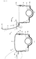
- Figs. 6(a) and 6(b) are sectional views along line A-A of Fig. 5(b), in which Fig. 6(a) shows the condition at normal time, and Fig. 6(b) shows the condition when the air bag 50 is inflated and developed.
- the inflator 29 for generating a gas for inflating and developing the air bag 50 is contained in the vicinity of a bottom portion of the lower-side casing 23a.
- the first tear lines 27 are each formed by imparting brittleness through molding in a small material thickness a boundary portion between the module cover 22 and the casing 23.
- projected stoppers 22a and 22b are formed over the whole width in the vehicle width direction.
- the gas generated by the inflator 29 is instantaneously supplied into the air bag 50 stored in its folded state, and, due to the pressure of the gas, the module cover 22 is pushed up from the inside.
- the second tear line 27 is ruptured while forming rupture surfaces 27a and 27b, which permits the air bag 50 to be inflated and developed to the upper side.
- the stoppers 22a and 22b make contact with each other at portion E in the figure so as thereby to make it difficult for the module cover 22 to be opened further.
- the module cover 22 can be developed to a predetermined angle.
- the tear lines as brittle portions are provided in the side surfaces of an upper portion of the air bag module, so that the toughness of the module cover surface against external factors can be markedly enhanced. For instance, even if a sticker is attached to the surface of the module cover or the surface is scratched, the inflation and development of the air bag will not thereby be influenced in any way; therefore, an air bag module cover suitable for application to a motorcycle can be obtained. In addition, since it is unnecessary to provide the module cover surface with a tear line, the degree of freedom in designing the module cover surface can be enhanced.
- the shape, structure, number, and the like of the tear lines are not limited to those in the above-described embodiments, and can be modified variously.
- the air bag module cover structure according to the present invention can naturally be applied to other vehicles than motorcycles.
Landscapes
- Engineering & Computer Science (AREA)
- Mechanical Engineering (AREA)
- Air Bags (AREA)
- Professional, Industrial, Or Sporting Protective Garments (AREA)
Abstract
Description
- The present invention relates to an air bag module cover structure, particularly to an air bag module cover structure suited to use for a motorcycle.
- Hitherto, various contrivances have been investigated for applying to a motorcycle an air bag for effectively holding a rider (passenger) when an excessive level of shock is exerted on a vehicle body. In general, a roughly box-like air bag module integrally containing therein a folded air bag together with an inflator for inflating and developing the air bag and the like has a configuration in which the surface(s) of an air bag module cover as a predetermined development surface(s) is provided with a tear line as a brittle portion. At the time of inflation and development of the air bag, the pressure inside the air bag is raised by a gas generated from the inflator, whereby the tear line is ruptured and the air bag is developed. The tear line is required to have such a brittleness as to be appropriately ruptured at the time of inflation and development of the air bag and, simultaneously, to have such an appropriate strength as not to be deformed or ruptured when touched by the rider (passenger) or the like.
-
Patent Document 1 discloses a configuration of an air bag module cover for application to an assistant driver's seat air bag system in a four-wheel vehicle, wherein a tear line formed across a development surface(s) is in the shape of a single arc. According to this air bag module cover, even when the tear line and the surrounding portion are pushed by the passenger or the like, the pushing force is dispersed to the arc-shaped peripheral portions, so that the tear line and the surrounding portion are enhanced in rigidity and are less liable to be depressed. In addition, both end portions of the first tear line in an arcuate shape are orthogonally intersecting with rectilinear second tear lines, so that, at the time of inflation and development of the air bag, the force exerted on the tear line is transmitted evenly, and smooth development of the air bag is realized. - On the other hand,
Patent Document 2 discloses a tear line structure formed in an air bag module cover for a four-wheel vehicle air bag system. In this tear line structure, an anti-leaking member provided for preventing a foamable resin of a foamable resin layer from flowing from a development portion into the air bag side, at the time of forming a perforation having a predetermined depth from the back side of the air bag module cover by laser processing, is removed only at the portion on the tear line, so that non-evenness of rupture of the tear line due to the anti-leaking member is obviated, and smooth development of the air bag is realized. - [Patent Document 1]
Japanese Patent Laid-open No. 2005-162033 - [Patent Document 2]
Japanese Patent Laid-open No. 2003-212075 - In general, the air bag module as above-mentioned is disposed in the vehicle in the condition where no obstacle is present between the air bag module and the passenger. Therefore, when the air bag module is installed on a motorcycle, the surface of the air bag module cover which is provided with a tear line is necessarily placed in an outdoor environment much different from the compartment environment in the case of a four-wheel vehicle. Accordingly, the tear line is not only put under influences of direct sunlight, winds, and rains but also highly possibly touched by the rider's hand when the rider gets on or gets off the motorcycle or pushed due to other external factor such as mischief. If the tear line should be damaged due to such a factor, the damage would possibly influence the inflating and developing action of the air bag.
- The technologies disclosed in
Patent Documents - It is an object of the present invention to solve the above-mentioned problems involved in the prior art, and to provide an air bag module cover structure suited to use on a motorcycle.
- In order to attain the above object, the present invention is firstly characterized in that, in an air bag module cover structure applied to a roughly rectangular parallelopiped-shaped air bag module, of four side surfaces of the air bag module, the three side surfaces other than the side surface facing to the vehicle front side are provided with tear lines at upper portions thereof.
- In addition, the present invention is secondly characterized in that the air bag module cover is developed toward the vehicle front side through rupture of the tear lines, and a stopper is provided on the vehicle front side of the air bag module cover.
- Further, the present invention is thirdly
characterized in that the side surface facing to the vehicle rear side of the air bag module is provided with a slit portion through which to pass a support belt connecting an air bag and a vehicle body to each other, and the tear lines are provided respectively in the side surface facing to the vehicle rear side excluding the slit portion and in both the side surfaces facing in the vehicle width direction. - According to the invention as set forth in
claim 1, there can be obtained an air bag module cover structure by which the toughness of the surface of the module cover against external factors can be markedly enhanced and which is suited to application to a motorcycle. In addition, even if a sticker is attached to the surface of the module cover or the surface is scratched, the inflation and development of the air bag will not thereby be influenced in any way. Further, the degree of freedom in designing the module cover surface can be enhanced. - According to the invention as set forth in
claim 2, the air bag module cover can be developed to a predetermined angle. - According to the invention as set forth in
claim 3, there can be obtained an air bag module cover structure in which the toughness of the module cover surface and the like can be enhanced, even in an air bag module having a support belt connecting the vehicle body and the air bag to each other. -
- Fig. 1 is a general illustration of a motorcycle according to one embodiment of the present invention.
- Fig. 2 is an enlarged view of a motorcycle according to one embodiment of the present invention.
- Fig. 3 is a perspective illustration of a motorcycle according to one embodiment of the present invention.
- Fig. 4 is a perspective view illustrating a embodiment of the present invention.
- Figs. 5(a) and 5(b) show a front view and a side view of an air bag module to which an air bag module cover structure according to one embodiment of the present invention is applied.
- Figs. 6(a) and 6(b) show sectional views of an air bag module according to one embodiment of the present invention.
- Now, a preferred embodiment of the present invention will be described in detail below referring to the drawings. Fig. 1 is a general illustration of a
motorcycle 1 according to one embodiment of the present invention. Aframe 2 of themotorcycle 1 is composed mainly of a left-right pair ofupper tubes head pipe 3.Lower tubes 4 are extended downwards from portions, in the vicinity of thehead pipe 3, of theupper tubes engine 15 as a drive source is fixedly suspended from the tip ends of thelower tubes 4. A left-right pair of front forks 7 steerable by asteering handle 4 are turnably supported on thehead pipe 3 throughlower brackets 6, and a front wheel WF is rotatably supported on lower end portions of the front forks 7. In addition, aseat frame 5 for supporting amain seat 10, arear seat 11, and the like is connected to the vehicle body rear side of theframe 2, and a rear wheel WR as a drive wheel is rotatably supported on a rear end portion of a swing arm (not shown) swingably connected to theframe 2. - The
motorcycle 1 according to this embodiment is provided with anair bag 50 which, when an excessive shock is exerted on the vehicle body, is inflated and developed into a roughly spherical body so sized as to range from the upper side of themain seat 10 into the vicinity of awindscreen 9, which is provided at an upper end portion of anupper cowl 8, and to make contact with ameter case 36. Anair bag module 20 integrally containing theair bag 50 and an inflator (not shown) for generating a gas for inflating and developing theair bag 50 is fixed to theupper tubes support belts 51 connected to rear portions of theair bag 50 are for keeping theair bag 50 in an appropriate position at the time of holding the rider. - Fig. 2 is an enlarged view of a part of the
motorcycle 1 according to one embodiment of the present invention. The same symbols as used above denote portions which are the same as or equivalent to the above-mentioned. The air bag module 20 (see Fig. 1) has a configuration in which the inflator and theair bag 50 in its folded state are contained in a box-shaped casing 23, and an upper portion thereof is covered with amodule cover 22. The air bag module is disposed between anignition cover 12 covering the upper side of a top bridge (not shown) connecting thesteering handle 4 and the front forks 7 to each other and an oilfeed port lid 13 located on the upper side of a fuel tank (not shown). At the time of inflation and development of theair bag 50, the gas generated by the inflator is instantaneously supplied into theair bag 50 inside thecasing 23, and the pressure of the gas opens themodule cover 22, with one side on the vehicle front side as an axis. An air bag module cover structure according to the present invention is applied to a tear line provided as a brittle portion between themodule cover 22 and thecasing 23. - In addition, the
support belt 51 contained in a folded state in a containingspace 65 under belt covers 14L and 14R at normal time is so configured that, upon inflation and development of theair bag 50, thesupport belts 51 are developed to the positions indicated by broken lines in the figure while forcibly opening the belt covers 14L and 14R to the left and right sides. - Incidentally, the
steering handle 4 is steered to the left side in the figure, but at the time of inflation and development of theair bag 50, a front lower portion of theair bag 50 is stably supported by four portions, i.e., portion I in the vicinity of a left-side switch portion 74L and portion J in the vicinity of a right-side switch portion 74R in a neutral condition of thesteering handle 4, plus portion H by themeter case 36 and portion K by themodule cover 22. Incidentally, lower end portions of thesupport belts 51 are firmly fastened to a vehicle body side member on the lower side of themain seat 10 located on the upper side of atop shelter 71R. - Fig. 3 is a perspective illustration of the
motorcycle 1 at the time of inflation and development of theair bag 50. Theair bag 50 is so configured that its surface on the rider's side becomes roughly V shaped upon inflation and development, for the purpose of effectively enveloping the rider. Further, theair bag 50 is so configured as to be supported not only by thesupport belts 51 but also by the whole of members located at a front lower portion of theair bag 50, such as thesteering handle 4, theignition cover 12, themeter cover 36, etc. In addition, theair bag 50 is provided in left and right surfaces of an upper portion thereof with vent holes 56 (for example, ϕ45) for discharging the gas at an appropriate rate while holding the rider. - Fig. 4 is a perspective view illustrating a mounting structure of the
air bag module 20. The same symbols as used above denote portions the same with or equivalent to the above-mentioned. A left-side support stay 21L and a right-side support stay 21R are fused to lower portions of thecasing 23 of theair bag module 20, and are fixed by predetermined bolts to support members 30 (not shown), 31, 32 which are fused to theupper tubes connector 25 provided on a side surface on the vehicle front side of thecasing 23 is for inputting an ignition signal to the inflator contained in thecasing 23. - An
air cleaner box 44 for filtering the outside air to be introduced into theengine 15 and anupper cover 41 thereof are so disposed as to be clamped between theupper tubes shaped audio unit 40 is arranged on the upper side thereof. In addition, an FI unit support stay 34 for fixing a fuel injection control (FI) unit and a left-side air duct 42L for introducing the outside air into theair cleaner box 44 from the vehicle front side are fixed to athird support stay 33 disposed between thecasing 23 and theupper tube 2L. Incidentally, aconnector 43 for outputting a signal from an intake air temperature sensor disposed in theair cleaner box 44 is disposed at a side surface of theupper cover 41. A side surface on the rider's side of thecasing 23 is provided withslits 24 as gaps for passing thesupport belts 51 therethrough. - According to the mounting structure of the
air bag module 20 as above-described, the space generated on the lower side of theair bag module 20 for attaining an optimum layout of theair bag module 20 can be effectively utilized as a space for arranging other component parts, so that a reduction in the volume of the space for arranging theair bag module 20 is realized. In view of the mounting condition shown in the figure, by removing the FI unit support stay 34 and thethird support stay 33, theaudio unit 40 and theupper cover 41 are removed on the vehicle left side, without moving and removing theair bag module 20. Therefore, maintenance work such as replacement of an air filter (not shown) disposed in theair cleaner box 44 can also be carried out easily. - Fig. 5(a) is a side view of the
air bag module 20, and Fig. 5(b) is a front view of theair bag module 20 as viewed from the rider's side. The same symbols as used above denote portions the same with or equivalent to the above-mentioned. The air bag module cover structure according to this embodiment is characterized in that tear lines as brittle portions are not provided in the surface of themodule cover 22 but provided in side surfaces of an upper portion of theair bag module 20. In this embodiment, both side surfaces facing in the vehicle width direction are each provided with afirst tear line 26 in portion B in the figure, and the front surface (facing to the vehicle rear side) as viewed from the rider's side is provided with asecond tear line 27 in portion C in the figure other than portion D in the figure as theslit 24. Therefore, at the time of inflation and developing of theair bag 50, the roughlyrectangular module cover 22 is developed in such a manner as to open a lid with one side on the vehicle front side as an axis, relative to thecasing 23. - Incidentally, in this embodiment, the
module cover 22 and thecasing 23 are component parts which are integrally molded from a synthetic resin. A metallic lower-side casing 23a for containing the inflator and the like and thecasing 23 are fastened to each other by a plurality ofclips 28. - Figs. 6(a) and 6(b) are sectional views along line A-A of Fig. 5(b), in which Fig. 6(a) shows the condition at normal time, and Fig. 6(b) shows the condition when the
air bag 50 is inflated and developed. The same symbols as used above denote portions the same with or equivalent to the above-mentioned. In Fig. 6(a), theinflator 29 for generating a gas for inflating and developing theair bag 50 is contained in the vicinity of a bottom portion of the lower-side casing 23a. Thefirst tear lines 27 are each formed by imparting brittleness through molding in a small material thickness a boundary portion between themodule cover 22 and thecasing 23. Besides, at upper portions of the surface on the vehicle front side of theair bag module 20, projectedstoppers - At the time of inflation and development of the
air bag 50 as shown in Fig. 6(b), the gas generated by theinflator 29 is instantaneously supplied into theair bag 50 stored in its folded state, and, due to the pressure of the gas, themodule cover 22 is pushed up from the inside. By the pushing force or pressure, thesecond tear line 27 is ruptured while formingrupture surfaces air bag 50 to be inflated and developed to the upper side. In this instance, as a characteristic configuration in this embodiment, thestoppers module cover 22 to be opened further. According to this configuration, themodule cover 22 can be developed to a predetermined angle. - As above-mentioned, according to the present invention, the tear lines as brittle portions are provided in the side surfaces of an upper portion of the air bag module, so that the toughness of the module cover surface against external factors can be markedly enhanced. For instance, even if a sticker is attached to the surface of the module cover or the surface is scratched, the inflation and development of the air bag will not thereby be influenced in any way; therefore, an air bag module cover suitable for application to a motorcycle can be obtained. In addition, since it is unnecessary to provide the module cover surface with a tear line, the degree of freedom in designing the module cover surface can be enhanced.
- Incidentally, the shape, structure, number, and the like of the tear lines are not limited to those in the above-described embodiments, and can be modified variously. Besides, the air bag module cover structure according to the present invention can naturally be applied to other vehicles than motorcycles.
- 20 air bag module, 21R right-side support stay, 21L left-side support stay, 22 module cover, 23 casing, 23a lower-side casing, 24 slit, 26 first tear line, 27 second tear line, 28 clip.
Claims (3)
- An air bag module cover structure applied to a roughly rectangular parallelopiped-shaped air bag module (20), wherein
of four side surfaces of said air bag module (20), the three side surfaces other than the side surface facing to the vehicle front side are provided with tear lines (26, 27) at upper portions thereof. - The air bag module cover structure as set force in claim 1, wherein said air bag module cover is developed toward the vehicle front side through rupture of said tear lines (26, 27), and a stopper is provided on the vehicle front side of said air bag module cover.
- The air bag module cover structure as set forth in claim 1 or 2, wherein the side surface facing to the vehicle rear side of said air bag module (20) is provided with a slit portion through which to pass a support belt connecting an air bag and a vehicle body to each other, and said tear lines (26, 27) are provided respectively in the side surface facing to the vehicle rear side excluding said slit portion and in both the side surfaces facing in the vehicle width direction.
Applications Claiming Priority (1)
| Application Number | Priority Date | Filing Date | Title |
|---|---|---|---|
| JP2005260083A JP2007069792A (en) | 2005-09-08 | 2005-09-08 | Airbag module cover structure |
Publications (2)
| Publication Number | Publication Date |
|---|---|
| EP1762440A1 true EP1762440A1 (en) | 2007-03-14 |
| EP1762440B1 EP1762440B1 (en) | 2008-03-05 |
Family
ID=36954220
Family Applications (1)
| Application Number | Title | Priority Date | Filing Date |
|---|---|---|---|
| EP06016112A Not-in-force EP1762440B1 (en) | 2005-09-08 | 2006-08-02 | Air bag module cover structure |
Country Status (9)
| Country | Link |
|---|---|
| EP (1) | EP1762440B1 (en) |
| JP (1) | JP2007069792A (en) |
| KR (1) | KR100861974B1 (en) |
| CN (1) | CN100462259C (en) |
| AU (1) | AU2006203451B2 (en) |
| BR (1) | BRPI0603689B1 (en) |
| CA (1) | CA2556978C (en) |
| DE (1) | DE602006000644T2 (en) |
| ES (1) | ES2302282T3 (en) |
Cited By (3)
| Publication number | Priority date | Publication date | Assignee | Title |
|---|---|---|---|---|
| EP2085271A1 (en) * | 2008-01-31 | 2009-08-05 | Honda Motor Co., Ltd | Airbag device |
| EP2692620A4 (en) * | 2011-03-31 | 2014-09-17 | Takata Corp | INFLATABLE SAFETY CUSHION DEVICE AND INFLATABLE SAFETY CUSHION COVER |
| US11279429B2 (en) * | 2018-04-27 | 2022-03-22 | Honda Motor Co., Ltd. | Airbag device for riding type vehicle |
Families Citing this family (1)
| Publication number | Priority date | Publication date | Assignee | Title |
|---|---|---|---|---|
| JP4702842B2 (en) | 2006-02-14 | 2011-06-15 | 本田技研工業株式会社 | Airbag module for vehicles |
Citations (5)
| Publication number | Priority date | Publication date | Assignee | Title |
|---|---|---|---|---|
| US6007090A (en) * | 1996-07-25 | 1999-12-28 | Honda Giken Kogyo Kabushiki Kaisha | Air bag device for a motorcycle |
| US6113133A (en) * | 1996-06-11 | 2000-09-05 | Honda Giken Kogyo Kabushiki Kaisha | Air bag device on a two-wheeled motor vehicle |
| JP2003212075A (en) | 2002-01-24 | 2003-07-30 | Mitsuboshi Belting Ltd | Tear-line structure of airbag door |
| US20050023803A1 (en) * | 2003-05-19 | 2005-02-03 | Takeshi Kuroe | Air bag system |
| JP2005162033A (en) | 2003-12-03 | 2005-06-23 | Ashimori Ind Co Ltd | Airbag lid |
Family Cites Families (9)
| Publication number | Priority date | Publication date | Assignee | Title |
|---|---|---|---|---|
| JPH0373251U (en) * | 1989-11-22 | 1991-07-24 | ||
| JPH06344842A (en) * | 1993-06-02 | 1994-12-20 | Mazda Motor Corp | Air bag structure for vehicle |
| JPH07291072A (en) * | 1994-04-26 | 1995-11-07 | Toyoda Gosei Co Ltd | Air bag device for front passenger seat |
| JPH08164814A (en) * | 1994-10-13 | 1996-06-25 | Sensor Technol Kk | Bag cover |
| JP4129136B2 (en) * | 2002-03-01 | 2008-08-06 | 本田技研工業株式会社 | Motorcycle |
| US7104566B2 (en) * | 2002-04-25 | 2006-09-12 | Delphi Technologies, Inc. | Airbag module and cover arrangement |
| JP2004314811A (en) * | 2003-04-16 | 2004-11-11 | Takata Corp | Airbag device, and motorcycle with the airbag device |
| US20040256843A1 (en) * | 2003-06-23 | 2004-12-23 | Toyoda Gosei Co., Ltd. | Head-protecting airbag device |
| JP4822777B2 (en) * | 2005-09-07 | 2011-11-24 | タカタ株式会社 | Airbag device, motorcycle with airbag device |
-
2005
- 2005-09-08 JP JP2005260083A patent/JP2007069792A/en active Pending
-
2006
- 2006-08-02 DE DE602006000644T patent/DE602006000644T2/en active Active
- 2006-08-02 ES ES06016112T patent/ES2302282T3/en active Active
- 2006-08-02 EP EP06016112A patent/EP1762440B1/en not_active Not-in-force
- 2006-08-10 AU AU2006203451A patent/AU2006203451B2/en not_active Ceased
- 2006-08-23 CA CA002556978A patent/CA2556978C/en not_active Expired - Fee Related
- 2006-08-31 KR KR1020060083342A patent/KR100861974B1/en not_active Expired - Fee Related
- 2006-09-06 CN CNB2006101267585A patent/CN100462259C/en not_active Expired - Fee Related
- 2006-09-06 BR BRPI0603689A patent/BRPI0603689B1/en not_active IP Right Cessation
Patent Citations (5)
| Publication number | Priority date | Publication date | Assignee | Title |
|---|---|---|---|---|
| US6113133A (en) * | 1996-06-11 | 2000-09-05 | Honda Giken Kogyo Kabushiki Kaisha | Air bag device on a two-wheeled motor vehicle |
| US6007090A (en) * | 1996-07-25 | 1999-12-28 | Honda Giken Kogyo Kabushiki Kaisha | Air bag device for a motorcycle |
| JP2003212075A (en) | 2002-01-24 | 2003-07-30 | Mitsuboshi Belting Ltd | Tear-line structure of airbag door |
| US20050023803A1 (en) * | 2003-05-19 | 2005-02-03 | Takeshi Kuroe | Air bag system |
| JP2005162033A (en) | 2003-12-03 | 2005-06-23 | Ashimori Ind Co Ltd | Airbag lid |
Cited By (5)
| Publication number | Priority date | Publication date | Assignee | Title |
|---|---|---|---|---|
| EP2085271A1 (en) * | 2008-01-31 | 2009-08-05 | Honda Motor Co., Ltd | Airbag device |
| US7900955B2 (en) | 2008-01-31 | 2011-03-08 | Honda Motor Co., Ltd. | Airbag device |
| EP2692620A4 (en) * | 2011-03-31 | 2014-09-17 | Takata Corp | INFLATABLE SAFETY CUSHION DEVICE AND INFLATABLE SAFETY CUSHION COVER |
| US8955873B2 (en) | 2011-03-31 | 2015-02-17 | Takata Corporation | Airbag apparatus and airbag cover |
| US11279429B2 (en) * | 2018-04-27 | 2022-03-22 | Honda Motor Co., Ltd. | Airbag device for riding type vehicle |
Also Published As
| Publication number | Publication date |
|---|---|
| AU2006203451A1 (en) | 2007-03-22 |
| AU2006203451B2 (en) | 2011-12-08 |
| BRPI0603689B1 (en) | 2017-03-07 |
| CN100462259C (en) | 2009-02-18 |
| JP2007069792A (en) | 2007-03-22 |
| DE602006000644T2 (en) | 2009-03-26 |
| ES2302282T3 (en) | 2008-07-01 |
| KR20070029056A (en) | 2007-03-13 |
| EP1762440B1 (en) | 2008-03-05 |
| CA2556978A1 (en) | 2007-03-08 |
| DE602006000644D1 (en) | 2008-04-17 |
| CN1927626A (en) | 2007-03-14 |
| CA2556978C (en) | 2009-05-19 |
| BRPI0603689A (en) | 2007-05-02 |
| KR100861974B1 (en) | 2008-10-07 |
Similar Documents
| Publication | Publication Date | Title |
|---|---|---|
| CN104816775B (en) | The airbag apparatus of saddle ride type vehicle | |
| JP2006062488A (en) | Air bag device for pedestrian protection | |
| JP2011000962A (en) | Airbag device of saddle-riding type vehicle | |
| US6846009B2 (en) | Airbag apparatus for a compact vehicle | |
| US7032923B2 (en) | Air bag apparatus for a small size vehicle | |
| CN110709315B (en) | Airbag device for saddle-ride type vehicle | |
| CN110678382B (en) | Airbag device for saddle-riding vehicle | |
| WO2019207780A1 (en) | Airbag device for saddle-type vehicles | |
| US6854762B2 (en) | Airbag system | |
| EP1762440B1 (en) | Air bag module cover structure | |
| EP1762442A1 (en) | Air bag module mounting structure | |
| WO2007094116A1 (en) | Airbag apparatus | |
| US7789416B2 (en) | Air bag module cover structure | |
| CN110691732B (en) | Airbag device for saddle-riding vehicle | |
| EP2085271B1 (en) | Airbag device | |
| JP4052850B2 (en) | Airbag device for small vehicle | |
| EP1762478B1 (en) | Air bag support belt storing structure | |
| EP2692620B1 (en) | Air bag device and air bag cover |
Legal Events
| Date | Code | Title | Description |
|---|---|---|---|
| PUAI | Public reference made under article 153(3) epc to a published international application that has entered the european phase |
Free format text: ORIGINAL CODE: 0009012 |
|
| 17P | Request for examination filed |
Effective date: 20060802 |
|
| AK | Designated contracting states |
Kind code of ref document: A1 Designated state(s): AT BE BG CH CY CZ DE DK EE ES FI FR GB GR HU IE IS IT LI LT LU LV MC NL PL PT RO SE SI SK TR |
|
| AX | Request for extension of the european patent |
Extension state: AL BA HR MK YU |
|
| 17Q | First examination report despatched |
Effective date: 20070524 |
|
| GRAP | Despatch of communication of intention to grant a patent |
Free format text: ORIGINAL CODE: EPIDOSNIGR1 |
|
| AKX | Designation fees paid |
Designated state(s): DE ES FR GB IT |
|
| GRAS | Grant fee paid |
Free format text: ORIGINAL CODE: EPIDOSNIGR3 |
|
| GRAA | (expected) grant |
Free format text: ORIGINAL CODE: 0009210 |
|
| AK | Designated contracting states |
Kind code of ref document: B1 Designated state(s): DE ES FR GB IT |
|
| REG | Reference to a national code |
Ref country code: GB Ref legal event code: FG4D |
|
| REF | Corresponds to: |
Ref document number: 602006000644 Country of ref document: DE Date of ref document: 20080417 Kind code of ref document: P |
|
| REG | Reference to a national code |
Ref country code: ES Ref legal event code: FG2A Ref document number: 2302282 Country of ref document: ES Kind code of ref document: T3 |
|
| ET | Fr: translation filed | ||
| PLBE | No opposition filed within time limit |
Free format text: ORIGINAL CODE: 0009261 |
|
| STAA | Information on the status of an ep patent application or granted ep patent |
Free format text: STATUS: NO OPPOSITION FILED WITHIN TIME LIMIT |
|
| 26N | No opposition filed |
Effective date: 20081208 |
|
| PGFP | Annual fee paid to national office [announced via postgrant information from national office to epo] |
Ref country code: FR Payment date: 20140808 Year of fee payment: 9 Ref country code: ES Payment date: 20140711 Year of fee payment: 9 |
|
| REG | Reference to a national code |
Ref country code: DE Ref legal event code: R084 Ref document number: 602006000644 Country of ref document: DE |
|
| REG | Reference to a national code |
Ref country code: GB Ref legal event code: 746 Effective date: 20150507 |
|
| REG | Reference to a national code |
Ref country code: DE Ref legal event code: R084 Ref document number: 602006000644 Country of ref document: DE Effective date: 20150505 |
|
| REG | Reference to a national code |
Ref country code: FR Ref legal event code: ST Effective date: 20160429 |
|
| PG25 | Lapsed in a contracting state [announced via postgrant information from national office to epo] |
Ref country code: FR Free format text: LAPSE BECAUSE OF NON-PAYMENT OF DUE FEES Effective date: 20150831 |
|
| PGFP | Annual fee paid to national office [announced via postgrant information from national office to epo] |
Ref country code: IT Payment date: 20160822 Year of fee payment: 11 Ref country code: GB Payment date: 20160727 Year of fee payment: 11 |
|
| PG25 | Lapsed in a contracting state [announced via postgrant information from national office to epo] |
Ref country code: ES Free format text: LAPSE BECAUSE OF NON-PAYMENT OF DUE FEES Effective date: 20150803 |
|
| GBPC | Gb: european patent ceased through non-payment of renewal fee |
Effective date: 20170802 |
|
| REG | Reference to a national code |
Ref country code: ES Ref legal event code: FD2A Effective date: 20180709 |
|
| REG | Reference to a national code |
Ref country code: ES Ref legal event code: FD2A Effective date: 20180710 |
|
| PG25 | Lapsed in a contracting state [announced via postgrant information from national office to epo] |
Ref country code: GB Free format text: LAPSE BECAUSE OF NON-PAYMENT OF DUE FEES Effective date: 20170802 |
|
| PG25 | Lapsed in a contracting state [announced via postgrant information from national office to epo] |
Ref country code: IT Free format text: LAPSE BECAUSE OF NON-PAYMENT OF DUE FEES Effective date: 20170802 |
|
| PGFP | Annual fee paid to national office [announced via postgrant information from national office to epo] |
Ref country code: DE Payment date: 20210630 Year of fee payment: 16 |
|
| REG | Reference to a national code |
Ref country code: DE Ref legal event code: R119 Ref document number: 602006000644 Country of ref document: DE |
|
| PG25 | Lapsed in a contracting state [announced via postgrant information from national office to epo] |
Ref country code: DE Free format text: LAPSE BECAUSE OF NON-PAYMENT OF DUE FEES Effective date: 20230301 |