EP1762270A1 - Device for determining cardiac parameters - Google Patents
Device for determining cardiac parameters Download PDFInfo
- Publication number
- EP1762270A1 EP1762270A1 EP06076542A EP06076542A EP1762270A1 EP 1762270 A1 EP1762270 A1 EP 1762270A1 EP 06076542 A EP06076542 A EP 06076542A EP 06076542 A EP06076542 A EP 06076542A EP 1762270 A1 EP1762270 A1 EP 1762270A1
- Authority
- EP
- European Patent Office
- Prior art keywords
- impedance
- evaluation unit
- function parameter
- cardiac function
- maximum
- Prior art date
- Legal status (The legal status is an assumption and is not a legal conclusion. Google has not performed a legal analysis and makes no representation as to the accuracy of the status listed.)
- Granted
Links
Images


Classifications
-
- A—HUMAN NECESSITIES
- A61—MEDICAL OR VETERINARY SCIENCE; HYGIENE
- A61B—DIAGNOSIS; SURGERY; IDENTIFICATION
- A61B5/00—Measuring for diagnostic purposes; Identification of persons
- A61B5/05—Detecting, measuring or recording for diagnosis by means of electric currents or magnetic fields; Measuring using microwaves or radio waves
- A61B5/053—Measuring electrical impedance or conductance of a portion of the body
- A61B5/0535—Impedance plethysmography
-
- A—HUMAN NECESSITIES
- A61—MEDICAL OR VETERINARY SCIENCE; HYGIENE
- A61B—DIAGNOSIS; SURGERY; IDENTIFICATION
- A61B5/00—Measuring for diagnostic purposes; Identification of persons
- A61B5/72—Signal processing specially adapted for physiological signals or for diagnostic purposes
- A61B5/7235—Details of waveform analysis
- A61B5/7239—Details of waveform analysis using differentiation including higher order derivatives
-
- A—HUMAN NECESSITIES
- A61—MEDICAL OR VETERINARY SCIENCE; HYGIENE
- A61N—ELECTROTHERAPY; MAGNETOTHERAPY; RADIATION THERAPY; ULTRASOUND THERAPY
- A61N1/00—Electrotherapy; Circuits therefor
- A61N1/18—Applying electric currents by contact electrodes
- A61N1/32—Applying electric currents by contact electrodes alternating or intermittent currents
- A61N1/36—Applying electric currents by contact electrodes alternating or intermittent currents for stimulation
- A61N1/362—Heart stimulators
- A61N1/365—Heart stimulators controlled by a physiological parameter, e.g. heart potential
- A61N1/36514—Heart stimulators controlled by a physiological parameter, e.g. heart potential controlled by a physiological quantity other than heart potential, e.g. blood pressure
- A61N1/36521—Heart stimulators controlled by a physiological parameter, e.g. heart potential controlled by a physiological quantity other than heart potential, e.g. blood pressure the parameter being derived from measurement of an electrical impedance
Definitions
- the invention relates to a device for determining cardiac function parameters by evaluating the intracardiac impedance profile.
- the device has an impedance measuring unit which has electrical connections, to which electrodes for outputting a current and for detecting a voltage are connected or permanently connected.
- the device has an evaluation unit, which is connected to the impedance measuring unit and is designed such that it can derive a cardiac function parameter from a time profile of the impedance determined by means of the impedance measuring unit.
- a suitable impedance measuring arrangement is for example from DE 103 61 143 known.
- the impedance measuring arrangement described there is designed to determine from the intracardiac detected impedance a cardiac function parameter proportional to the stroke volume of the heart, namely the impact impedance.
- the stroke volume describes the volume of blood that is delivered by the heart during an ejection phase (systole).
- the difference between the end-diastolic impedance (at the end of the filling phase (diastole) of the heart) and the end-systolic impedance at the end of the ejection phase (systole) is determined.
- the impedance at maximum filled heart at the end of diastole is smaller than at maximum contracted ventricle at the end of systole.
- the end-diastolic impedance coincides more or less with the minimum of the impedance curve during a cardiac cycle, while the end-systolic impedance is the maximum of the impedance curve during a cardiac cycle.
- An impedance measuring arrangement which is also preferred for the present invention is a quadrupole arrangement as shown in FIG DE 103 61 143 is shown and described in the accompanying description.
- a pulsed constant current is delivered between the right ventricular tip electrode terminal and the right ventricular ring electrode terminal.
- a measurement of the voltage produced by the current in this preferred case between the connection for a left ventricular tip electrode and the connection for a left ventricular ring electrode.
- the device according to the invention affected here is preferably part of an electrostimulation device, which in the preferred case can be implanted.
- an implantable electrostimulation device can be, for example, an implantable cardiac pacemaker or also an implantable cardioverter / defibrillator (ICD) or a combination of these implants.
- ICD implantable cardioverter / defibrillator
- the aim of the device claimed here is to enable an expanded and improved cardiac function analysis which, as a result, opens up extended diagnostic and therapeutic options.
- a device suitable for this purpose is to be created.
- this object is achieved in that the evaluation unit of the device described above is designed so that it evaluates the course of the impedance signal assigned to a diastole during operation and derives a value of a cardiac function parameter characterizing the behavior of a heart during diastole.
- the invention is based on the finding that valuable information about the behavior of the heart during diastole can also be gathered from the course of the intracardiac impedance.
- the device according to the invention has Accordingly, an evaluation unit that evaluates not only impedance values at the beginning of the diastole and at the end of the diastole, but also those impedance values that occur during diastole to determine a cardiac function parameter.
- the device allows for the first time detecting diastolic heart failure by intracardiac impedance measurement. The detection of diastolic heart failure is thus for the first time also possible by means of an implantable device, since a device of the type described here can be easily integrated into an implant.
- Heart defects affect the pumping power of a heart. As a rule, both the systolic and the diastolic function of the heart is impaired. In some patients, the relaxation process of the myocardium is mainly impaired. Patients with diastolic heart disease show clinical symptoms that are consistent with the symptoms of congestive heart failure (CHF), although systolic function of the heart is normal or only marginally impaired. Diastolic heart failure or diastolic heart failure may be caused by abnormal relaxation (relaxation) of the left ventricle, or by increased passive stiffness of the myocardium or by other factors. The disturbed diastolic function affects the filling of the ventricle during the passive diastolic phase.
- CHF congestive heart failure
- the passive filling of the ventricle ie the ventricular filling phase due to the relaxation of the myocardium, makes the largest contribution to the total filling of the ventricle.
- the atrial contraction contributes only to a portion of the blood volume that flows into the ventricle.
- the impaired relaxation of the ventricle results in a compensatory increase in filling pressure, which in turn leads to increased left atrial pressure and increased capillary pressure (PCWP).
- PCWP capillary pressure
- the evaluation unit is designed to determine the maximum impedance drop during the passive diastolic phase, ie the negative maximum of the gradient of the impedance curve.
- the gradient of the impedance curve is the first derivative (slope) of the impedance curve with respect to time, referred to as the first time derivative of the impedance curve.
- the negative maximum of the gradient of the impedance curve is a useful cardiac function parameter because it is proportional to the early left ventricular diastolic filling rate and characterizes the course of ventricular myocardial relaxation during diastole.
- the negative slope of the impedance curve is proportional to the flow rate of the blood entering the ventricle. Therefore, the pressure difference between the left ventricle and the left atrium, based on the Bernoulli equation, which is proportional to the pressure difference to the square of the flow velocity, can be derived from the (negative) slope of the impedance curve. The square of the maximum of this negative slope is thus proportional to the maximum pressure difference between the left ventricle and the left atrium.
- the evaluation unit is preferably designed to determine the time duration between the beginning of the impedance decrease and the subsequent occurrence of the maximum negative gradient as the value of an alternative cardiac function parameter by evaluating the impedance profile.
- This heart function parameter is referred to below as the fill acceleration time.
- the onset of diastole that is, the onset of blood flow through the mitral valve is thus by detecting the onset the impedance decrease determined.
- the time of occurrence of the impedance maximum within a cardiac cycle can also be determined.
- the so determined Medbevantungszeit is the time between the onset of blood flow through the mitral valve to reach the maximum flow rate.
- This filling acceleration time correlates with the isovolumic relaxation period and is a measure of the relaxation capacity of the myocardium. In patients with diastolic heart failure, the filling acceleration time is prolonged.
- the evaluation unit is designed to determine a filling delay time as cardiac function parameter by evaluating the impedance curve. For this purpose, the evaluation unit determines the time duration between the occurrence of the maximum negative gradient of the impedance curve and the apex of a parabolic approximation function of the impedance curve, starting with the occurrence of the maximum negative gradient of the impedance curve.
- the impedance curve from the time of occurrence of the maximum negative gradient on can also be approximated by an exponential function whose time constant LV ⁇ (Z) then represents the filling delay time.
- the evaluation unit is designed, by evaluating the impedance curve, the ratio of the negative maximum of the gradient of the impedance curve between the beginning of the decrease of the impedance and a subsequent atrial contraction to the negative maximum of the gradient of the impedance curve between this atrial contraction and the following To determine the increase of the impedance curve again.
- the ratio of the maximum flow velocity of the E-wave which describes the ventricular contribution to the filling of the left ventricle
- the A-wave which is the atrial contribution to the filling of the left ventricle
- the determination of the duration of diastole is another cardiac function parameter, for the determination of which the evaluation unit is preferably designed.
- This time period determines the evaluation unit in the preferred embodiment in that the evaluation unit first detects the beginning of the drop of the impedance curve after reaching the impedance maximum during a cardiac cycle and then the time of occurrence of the subsequent impedance minimum.
- the evaluation unit can be designed to additionally determine values of cardiac function parameters that influence the behavior of the heart describe a systole.
- the evaluation unit is designed to determine the course of the intracardiac impedance during systole, ie the ejection phase of the heart chamber, which is accompanied by a contraction of the respective ventricle.
- Such a systolic cardiac function parameter for the determination of which the evaluation unit is preferably designed, is the positive maximum of the gradient of the impedance course during systole.
- the impedance increases because blood is displaced from the ventricle.
- the slope of the impedance curve ie the first time derivative of the impedance curve during the ejection phase, corresponds to the rate of change of the left ventricular volume.
- the slope of the impedance is proportional to the outflow velocity of the blood.
- the evaluation unit is designed to form the maximum of the gradient of the gradient of the impedance curve, that is to say its second derivative with respect to time.
- the second temporal derivative of the impedance curve LVd 2 Z / dt 2 multiplied by the first derivative LVdZ / dt is a marker for the maximum left ventricular pressure change LVdp / dt Max , which is a measure of the contractility of the left ventricle is.
- the function of the aortic region close to the heart is referred to as the vesicular function of the atrium, so that it can elastically expand and contract again, thus smoothing out the pulsation of the blood flow.
- the evaluation unit it is designed by evaluating the impedance curve to determine the duration of the pre-ejection phase (pre-ejection phase, pre-ejection period, PEP) as cardiac function parameter, by the evaluation unit determining the time duration between the electrical activation of the ventricular myocardium and the beginning of the impedance increase.
- the time of the electrical activation of the ventricular myocardium can be determined by the detection unit by detecting an R-wave in the preferably intracardiacly recorded electrocardiogram (ECG) or by detecting the time of delivery of a left ventricular stimulation pulse.
- ECG intracardiacly recorded electrocardiogram
- the evaluation unit can be designed to determine the time at which the intracardiac impedance exceeds a threshold value related to the impedance minimum.
- the evaluation unit is designed to determine the duration of the left ventricular ejection time by evaluating the impedance curve, in that the evaluation unit determines the time duration between the beginning of the impedance increase and the maximum of the impedance curve.
- the beginning of the impedance increase that is, the time from which the intracardiac impedance increases again over time corresponds to the opening of the aortic valve.
- the maximum of the impedance curve corresponds to the end of the ejection phase and corresponds to the closing of the aortic valve.
- An embodiment of the evaluation unit is also preferred, in which the evaluation unit is designed to determine the left ventricular ejection acceleration time as cardiac function parameter by evaluating the impedance curve.
- the evaluation unit is designed to determine the time duration between the beginning of the impedance increase and the subsequent occurrence of the maximum positive gradient of the impedance profile.
- the thus determined acceleration time is the time between the start of the ejection phase and the occurrence of the maximum flow velocity of the blood.
- the evaluation unit may be designed to determine the left ventricular ejection delay time by evaluating the impedance curve. For this purpose, the evaluation unit determines the time duration between the occurrence of the maximum positive gradient of the impedance curve during the systole and the subsequent maximum of the impedance curve.
- the relationship between the ejection acceleration time and the ejection delay time is influenced by a possible stenosis of the aorta: An increasing stenosis (narrowing) of the aorta increases the proportion of the ejection acceleration time over the total duration of the systole.
- the evaluation unit is designed to determine the electromechanical delay time as the time difference between the electrical activation of the ventricle and the onset of the impedance increase during the systolic phase.
- the evaluation unit is connected to an impedance measuring unit, which interacts with impedance measuring electrodes in such a way that they engage detected local right ventricular or left ventricular impedance signal, for example by means of a unipolar or bipolar impedance measuring arrangement in the right or left ventricle.
- the electro-mechanical delay time differs from the duration of the pre-ejection period (PEP), which is based on a whole heart rate Impedance curve is determined.
- PEP pre-ejection period
- the time of the electrical activation of the respective ventricle can be determined by the evaluating unit by evaluating an intracardiac electrocardiogram, in which the evaluation unit determines the time of occurrence of an R wave in this electrocardiogram.
- the device preferably has a memory in order to be able to record the previously described cardiac function parameters determined by evaluating the intracardiac impedance characteristic for diagnostic purposes.
- the memory preferably comprises at least two memory areas, of which a first memory area is provided for cardiac function parameter values acquired during a phase of physical activity of the patient, and a second memory area is for storing cardiac function parameter values acquired during a resting period of the patient.
- the device preferably has an activity detection unit. This may for example be coupled with a physiological sensor for determining the hemodynamic requirements of the patient, as is frequently used in rate-adaptive cardiac pacemakers for the purpose of adapting the stimulation rate. Such a physiological sensor may for example be an acceleration sensor.
- the evaluation unit is connected directly or indirectly to the activity detection unit and configured to store the cardiac function parameter values determined by the evaluation unit in the first or in the second memory area of the memory, depending on the output signal of the activity detection unit.
- the evaluation unit is also designed to average cardiac function parameter values for a respective cardiac function parameter over time.
- the evaluation unit accesses heart function parameter values stored in the memory.
- the evaluation unit can also be designed to generate histograms on the basis of the stored cardiac function parameter values.
- the device preferably has an activity detection unit which is designed to differentiate a plurality of states of physical activity of different intensities.
- the memory has a plurality of memory areas and the evaluation unit is designed to store heart function parameter values as a function of the output signal of the activity detection unit depending on the intensity of the associated physical activity in one of the memory areas.
- the evaluation unit can additionally be designed to examine cardiac function parameter values of a cardiac function parameter in order to determine whether the respective cardiac function parameter alternates from cardiac cycle to cardiac cycle (from heartbeat to beat).
- cardiac function parameter values of a cardiac function parameter in order to determine whether the respective cardiac function parameter alternates from cardiac cycle to cardiac cycle (from heartbeat to beat).
- alternance Such an alternating behavior of a cardiac function parameter from beat to beat is also referred to below as alternance.
- the cardiac function parameter values determined by the evaluation unit and stored in the memory and values derived therefrom, such as mean values over time or histogram values, can be transmitted to a receiver outside the device by means of a telemetry unit of the device.
- a telemetry unit is preferably provided, which is connected to the memory and has at least one transmitting unit for the wireless transmission of data.
- Such a device allows the various in the memory stored values to a central data processing unit, which may have a larger storage capacity and a greater computing capacity and therefore is suitable for a more extensive evaluation of the data determined by the evaluation unit.
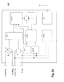
- FIG. 1 a shows an implant 10, which is a pacemaker, for example.
- the implant 10 has a hermetically sealed metal housing 12 and a header 14 made of transparent plastic, which has a plurality of sockets for connecting electrode lines.
- the electrode lead terminals in the header 14 are electrically connected to a control circuit inside the housing of the pacemaker 10.
- a total of three electrode lines are connected to the electrode line connections, namely a right-atrial electrode line 16, a right-ventricular electrode line 18 and a left-ventricular electrode line 20.
- the right atrial electrode line 16 carries a right atrial stimulation electrode 22.
- the right ventricular electrode line 18 carries a right ventricular ring electrode 24 and a right ventricular tip electrode (tip electrode) 26.
- the left ventricular electrode lead 20 is over the right atrium of the heart shown schematically in Figure 1a and the coronary sinus of the heart to the periphery of the left ventricle.
- the left ventricular electrode lead 20 carries a left ventricular ring electrode 28 and a left ventricular tip electrode 30.
- the implant 10 has an impedance measuring unit (see FIG. 2) that of the preferred embodiment (FIG. 2a) shown here for the purpose of impedance measurement with the right ventricular ring electrode 24 and the right ventricular tip electrode 26 and the left ventricular ring electrode 28 and the left ventricular tip electrode 30 is connected.
- the delivery of a biphasic, pulsed measuring current takes place via the right-ventricular ring electrode 24 and the right ventricular tip electrode 26, that is, in the right ventricle.
- the measurement of the voltage caused by the current takes place via the left ventricular ring electrode 28 and the left ventricular tip electrode 30.
- the current for impedance measurement is output in biphasic pulses, with two antiphase constant-current pulses directly following each other and each forming a pulse packet.
- the individual pulse packets have a time interval which is substantially greater than the duration of the respective pulse packet.
- the two DC pulses within the Pululseveres each have the same strength, but with different polarity and are each the same length. Typical values for the strength of the DC pulses are between 50 ⁇ A and 600 ⁇ A.
- a typical pulse duration of a single current pulse is 15 ⁇ s.
- the distance of the pulse packets from each other for example, 500 times greater than the duration of a current pulse.
- the two DC pulses of a pulse packet can follow one another with a time interval corresponding to the duration of a DC pulse. Between two opposite-phase DC pulses of a pulse packet then results in each case a gap of the duration of a DC pulse, during which no direct current is delivered.
- the pulse packets are output phase-alternately, that is, strictly alternately a pulse packet begins, for example with a negative DC pulse and ends with a positive DC pulse and the subsequent pulse packet starts with a positive DC pulse and ends with a negative DC pulse and immediately.
- FIGS. 2a and 2b respectively show a block diagram with the components of a circuit inside the housing 12 of the cardiac pacemaker 10 which are essential with respect to the invention concerned.
- These components are an impedance measuring unit IMP, which on the one hand is equipped with a constant current generator I, which generates a pulsed, biphasic constant current and outputs a terminal RV ring for the right ventricular ring electrode 24 and a connection RV tip for right ventricular tip electrode 26.
- the impedance measuring unit is connected to a voltage measuring unit U, which in turn is connected to two terminals, via which the respective voltage is detected, which causes the output for impedance measurement purposes constant current.
- the voltage measuring unit U is connected to a connection LV ring for the left ventricular ring electrode 28 and to a connection LV tip for the left ventricular tip electrode 30.
- the voltage measuring unit U is connected, on the one hand, to a terminal RV tip for the right ventricular tip electrode 26 and, on the other hand, to a connection LV tip for the left ventricular tip electrode 30.
- the current is supplied via the right ventricular ring electrode 24 at the RV-ring connection and the left-ventricular ring electrode 28 at the LV-ring connection.
- the impedance measuring unit IMP is designed to detect the course of the intracardiac impedance in time-sampled form (sampled) and to pass on a corresponding impedance progression signal to an evaluation unit EVAL.
- the evaluation unit EVAL is designed to evaluate at least the impedance curve during the diastole according to one of the previously described variants.
- FIG. 3b A typical course of the intracardiac impedance is shown in FIG. 3b and FIG. An explanation of the impedance curve will be made in conjunction with the description of these figures. In connection with FIG. 4, in particular those points in time of the gradients (gradients) maxima and minima of the impedance curve which are used for the determination of the above-mentioned cardiac function parameters will be explained.
- the evaluation of the impedance curve by the evaluation unit is made in some cases meaningful way with respect to a preferably intracardiac detected electrocardiogram. This has already been mentioned above with particular reference to the determination of the duration of the pre-ejection period (PEP).
- iEGM intracardiac electrogram
- known cardiac pacemakers also already have corresponding sensing units SENS, which are connected to the connection for the right ventricular ring electrode 24 and the right ventricular tip electrode 28, as shown in the exemplary embodiment according to FIGS. 2a and 2b.
- the intracardiac electrocardiogram shows the electrical potentials associated with the contraction or expansion of the myocardium. A typical electrocardiogram course is shown in FIG. 3a.
- the electrocardiogram shows the potentials associated with a depolarization of the ventricular myocardium and thus with a ventricular contraction. These potentials can be taken from the electrocardiogram as an R-wave.
- the repolarization of the myocardium and thus the onset of relaxation (relaxation) of the myocardium coincides with the T-wave in the electrocardiogram.
- a P-wave indicates the contraction of the atrium.
- pacemakers have a control unit CTRL which is designed to detect the time of occurrence of an R-wave and a P-wave and to generate a corresponding marker signal which identifies a ventricular contraction (V) or an atrial contraction (A).
- the corresponding marker signals V and A characterizing the time of occurrence of an R-wave or a P-wave are also shown in FIGS. 4 and 5.
- the pacemaker 10 or 10 has an activity sensor ACT which serves, on the one hand, in the usual manner to detect phases of physical activity of a patient.
- Physical activity is usually associated with an increased metabolic demand, so that in known cardiac pacemakers to detect an increased physical activity of the patient with Help of the activity sensor ACT leads to an increase of the stimulation rate.
- the output signal of the activity sensor ACT is additionally supplied to the evaluation unit EVAL for evaluation of the impedance signal.
- the evaluation unit EVAL uses the output signal of the activity sensor ACT to store determined cardiac function parameter values in one of the two memory areas of the memory MEM, depending on whether a cardiac function parameter value was acquired during a phase of physical activity of the patient or during a resting phase of the patient.
- the memory MEM is finally connected to a telemetry unit TEL, which contains at least one transmitter unit and is designed to transmit data from the memory MEM wirelessly to a receiver outside the implant 10.
- FIG. 3 a shows a typical electrocardiogram
- FIG. 3 b shows a typical course of the left ventricular impedance in synoptic association with the electrocardiogram.
- the electrocardiogram results from electrical potentials of the myocardium, which occur together with the contraction and relaxation of the myocardium.
- a contraction of the myocardial tissue - here the contraction of the left ventricle - is triggered by an electrical potential (an electrical excitation), which leads to a depolarization of the heart muscle cells and spreads from an excitation site to the entire myocardium of a ventricle and thus to the contraction of the heart Heart chamber leads.
- an electrical excitation an electrical excitation
- the repolarization of the heart tissue which is accompanied by the relaxation (relaxation) of the myocardium, coincides with the recognizable in the electrocardiogram T-wave.
- a P-wave results from the electrical potentials associated with the contraction of the atrium.
- the impedance has a minimum at about the time of occurrence of the R wave.
- the ventricle has its largest volume and therefore has the lowest impedance.
- the left ventricular impedance increase phase is associated with the heart's ejection phase (systole), during which blood is forced from the ventricle through the aortic valve into the aorta.
- the heart muscle tissue myocardium
- the beginning of the repolarization can be seen in the electrocardiogram as a T-wave and causes the left ventricular impedance to drop again once the impedance maximum has been reached.
- the decrease in left ventricular impedance reflects the volume of the left ventricle that increases with increasing relaxation of the myocardium.
- FIG. 4 shows the times and values which the evaluation unit determines for determining the cardiac function parameter values. Also shown in FIG. 4 are most of the cardiac function parameters whose values the evaluation unit is designed to determine.
- the evaluation unit EVAL carries out the assignment of values and times to be taken from the impedance profile to the times of occurrence of an R wave and a P wave in the electrocardiogram by evaluating corresponding marker signals V and A.
- FIG. 4 shows that the systole, ie the ejection phase, extends from the time of depolarization of the ventricular myocardium-characterized by a V marker-until the minimum ventricular chamber volume is reached-characterized by the maximum of the impedance profile.
- the diastole of particular interest in connection with the invention extends in time with respect to the time of occurrence of the impedance maximum until the next ventricular depolarization.
- the pre-ejection phase PEP extends from the onset of ventricular depolarization (V-markers) to the onset of an increase in impedance.
- the ejection acceleration time (Ejection Acceleration Time) extends from this significant increase in left ventricular impedance to the point in time at which the impedance curve has its largest positive increase, that is, the gradient of the impedance curve is greatest. From the time of occurrence of the maximum slope (maximum gradient) of the impedance curve until reaching the maximum impedance, the ejection delay time (Ejection Deceleration Time) extends. Eject Acceleration Time and Eject Delay Time together make the left ventricular ejection time (LVET).
- the ejection phase of the heart ends, ie the systole, and the filling phase, ie the diastole, begins.
- the diastole begins with the filling acceleration time (Filling Acceleration Time), which extends in time from the occurrence of the maximum of the impedance curve to the time of occurrence of the maximum negative slope of the impedance curve (maximum negative gradient dZ / dt min ).
- the Filling Deceleration Time begins with the time of occurrence of the maximum negative gradient and extends to the occurrence of the apex of a parabolic approximation function of the impedance curve, starting with the time of occurrence of the maximum negative slope.
- FIG. 5a shows a typical, alternating impedance curve over several cycles in relation to the occurrence of atrial and ventricular events (depolarizations) characterized by A-markers and V-markers.
- the respective ejection acceleration time (Ejection Acceleration Time) is entered in FIG. 5a.
- FIG. 5b the values for the maximum gradient of the impedance profile and for the ejection acceleration time for each of the four cardiac cycles shown are plotted in a diagram. It can be clearly seen that both cardiac function parameters alternate from cardiac cycle to cardiac cycle. A look at FIG. 5a shows that a corresponding alternation can also be recognized with respect to the maximum amplitude value of the impedance profile.
- the evaluation unit EVAL is designed to detect such an alternation for one or more of the cardiac function parameters detected by the evaluation unit EVAL. To determine such an alternation and / or a variability of the cardiac function parameters, the evaluation unit is designed to carry out the change of the cardiac function parameters in the time or in the frequency range. A determination of alternation and variability may be made for one or more of the cardiac function parameters.
- the evaluation unit EVAL can derive different risk marker signals from the alternances and variabilities determined in this way.
- risk marker signals can be used, for example, as short-term predictors of life-threatening Cardiac arrhythmias serve as alternations or variabilities of impedance-derived cardiac function parameter values may be precursors of ventricular fibrillation.
- the prediction of ventricular fibrillation is based on the evaluation of less recent cardiac cycles, thus represents a short-term evaluation.
- a long-term evaluation of the risk parameters can predict the risk of sudden cardiac death or to monitor the course of heart disease such as severe congestive heart failure serve.
- the evaluation unit EVAL can be designed to optimize electrotherapy by the pacemaker 10, ie, in particular to set the decisive parameters for the electrical stimulation of the heart, such as the time and strength of stimulation pulses as a function of the cardiac function parameter values determined by the evaluation unit EVAL.
- These therapy parameters to be optimized in this way include the stimulation rate and the atrioventricular delay time.
- the evaluation unit may also be designed to optimize the interventricular delay time or the biventricular pacing mode on the basis of the impedance-derived cardiac function parameter values.
- the evaluation unit determines whether the pacing should occur only in the left ventricle, only in the right ventricle, or both ventricle pacing, depending on which pacing waveform results in the maximum value of the gradient of the impedance curve during systole. In the same sense, the evaluation unit also optimizes the interventricular delay time.
- the cardiac function parameter values determined by the evaluation unit EVAL can also be evaluated to optimize drug therapy.
Abstract
Description
Die Erfindung betrifft eine Vorrichtung zum Bestimmen von Herzfunktionsparametern durch Auswerten des intrakardialen Impedanzverlaufes. Die Vorrichtung weist hierzu eine Impedanzmesseinheit auf, die elektrische Anschlüsse aufweist, an die Elektroden zum Abgeben eines Stromes und zum Erfassen einer Spannung anzuschließen oder permanent angeschlossen sind. Außerdem weist die Vorrichtung eine Auswerteeinheit auf, die mit der Impedanzmesseinheit verbunden und derart ausgebildet ist, dass sie aus einem mittels der Impedanzmesseinheit ermittelten zeitlichen Verlauf der Impedanz einen Herzfunktionsparameter ableiten kann.The invention relates to a device for determining cardiac function parameters by evaluating the intracardiac impedance profile. For this purpose, the device has an impedance measuring unit which has electrical connections, to which electrodes for outputting a current and for detecting a voltage are connected or permanently connected. In addition, the device has an evaluation unit, which is connected to the impedance measuring unit and is designed such that it can derive a cardiac function parameter from a time profile of the impedance determined by means of the impedance measuring unit.
Eine geeignete Impedanzmessanordnung ist beispielsweise aus der
Eine auch für die vorliegende Erfindung bevorzugte Impedanzmessanordnung ist eine quadropolare Anordnung wie sie in Figur 1a der
Die hier betroffene, erfindungsgemäße Vorrichtung ist vorzugsweise Bestandteil eines Elektrostimulationsgerätes, welches im bevorzugten Fall implantierbar ist. Ein solches implantierbares Elektrostimulationsgerät kann beispielsweise ein implantierbarer Herzschrittmacher oder auch ein implantierbarer Kardioverter/Defibrillator (ICD) oder eine Kombination aus diesen Implantaten sein.The device according to the invention affected here is preferably part of an electrostimulation device, which in the preferred case can be implanted. Such an implantable electrostimulation device can be, for example, an implantable cardiac pacemaker or also an implantable cardioverter / defibrillator (ICD) or a combination of these implants.
Ausgehend vom bekannten Stand der Technik wird mit der hier beanspruchten Vorrichtung das Ziel verfolgt, eine erweiterte und verbesserte Herzfunktionsanalyse zu ermöglichen, die im Ergebnis erweiterte Diagnose- und Therapiemöglichkeiten eröffnet. Mit der Erfindung soll eine dafür geeignete Vorrichtung geschaffen werden.Starting from the known state of the art, the aim of the device claimed here is to enable an expanded and improved cardiac function analysis which, as a result, opens up extended diagnostic and therapeutic options. With the invention, a device suitable for this purpose is to be created.
Erfindungsgemäß wird dieses Ziel dadurch erreicht, dass die Auswerteeinheit der eingangs beschriebenen Vorrichtung so ausgebildet ist, dass sie im Betrieb den einer Diastole zugeordneten Verlauf des Impedanzsignals auswertet und einen das Verhalten eines Herzens während der Diastole kennzeichnenden Wert eines Herzfunktionsparameters ableitet.According to the invention, this object is achieved in that the evaluation unit of the device described above is designed so that it evaluates the course of the impedance signal assigned to a diastole during operation and derives a value of a cardiac function parameter characterizing the behavior of a heart during diastole.
Die Erfindung beruht auf der Erkenntnis, dass dem Verlauf der intrakardialen Impedanz auch wertvolle Informationen zum Verhalten des Herzens während der Diastole zu entnehmen sind. Die erfindungsgemäße Vorrichtung besitzt demgemäß eine Auswerteeinheit, die zur Ermittlung eines Herzfunktionsparameters nicht nur Impedanzwerte zu Beginn der Diastole und am Ende der Diastole auswertet, sondern auch solche Impedanzwerte, die während der Diastole auftreten. Damit ermöglicht die Vorrichtung erstmals das Erfassen diastolischen Herzversagens mittels intrakardialer Impedanzmessung. Das Erfassen diastolischen Herzversagens wird damit erstmals auch mittels einer implantierbaren Vorrichtung möglich, da sich eine Vorrichtung der hier beschriebenen Art leicht in ein Implantat integrieren lässt.The invention is based on the finding that valuable information about the behavior of the heart during diastole can also be gathered from the course of the intracardiac impedance. The device according to the invention has Accordingly, an evaluation unit that evaluates not only impedance values at the beginning of the diastole and at the end of the diastole, but also those impedance values that occur during diastole to determine a cardiac function parameter. Thus, the device allows for the first time detecting diastolic heart failure by intracardiac impedance measurement. The detection of diastolic heart failure is thus for the first time also possible by means of an implantable device, since a device of the type described here can be easily integrated into an implant.
Herzfehler beeinträchtigen die Pumpleistung eines Herzens. In der Regel ist sowohl die systolische als auch die diastolische Funktion des Herzens beeinträchtigt. Bei einigen Patienten ist hauptsächlich der Relaxations-Prozess des Myokards beeinträchtigt. Patienten mit einem diastolischen Herzfehler zeigen klinische Symptome, die den Symptomen entsprechen, die bei systolischen kongestiven Herzversagen (CHF: Congestive Heart Failure) auftreten, obwohl die systolische Funktion des Herzens normal ist oder nur geringfügig beeinträchtigt. Diastolische Herzfehler beziehungsweise diastolisches Herzversagen können durch eine abnormale Relaxation (Entspannung) des linken Ventrikels verursacht sein, oder durch eine erhöhte passive Steifigkeit des Myokards oder durch andere Faktoren. Die gestörte diastolische Funktion beeinträchtigt die Füllung des Ventrikels während der passiven diastolischen Phase. Die passive Füllung des Ventrikels, das heißt die ventrikuläre Füllungsphase aufgrund der Relaxation des Myokards leistet den größten Beitrag zur Gesamtfüllung des Ventrikels. Die atriale Kontraktion trägt nur zu einem Teil des Blutvolumens bei, das in den Ventrikel fließt. Die beeinträchtigte Relaxation des Ventrikel führt zu einem kompensatorischen Ansteigen des Füllungsdruckes, was wiederum zu einem erhöhten linksatrialen Druck und zu einem erhöhten Kapillarverschlussdruck (PCWP) führt. Wenn nur diastolisches Herzversagen vorliegt, wird das end-diastolische Volumen nicht erhöht und die systolische Funktion bleibt normal. Es wird geschätzt, dass ungefähr ein Drittel aller CHF-Patienten an diastolischem Herzversagen leiden.Heart defects affect the pumping power of a heart. As a rule, both the systolic and the diastolic function of the heart is impaired. In some patients, the relaxation process of the myocardium is mainly impaired. Patients with diastolic heart disease show clinical symptoms that are consistent with the symptoms of congestive heart failure (CHF), although systolic function of the heart is normal or only marginally impaired. Diastolic heart failure or diastolic heart failure may be caused by abnormal relaxation (relaxation) of the left ventricle, or by increased passive stiffness of the myocardium or by other factors. The disturbed diastolic function affects the filling of the ventricle during the passive diastolic phase. The passive filling of the ventricle, ie the ventricular filling phase due to the relaxation of the myocardium, makes the largest contribution to the total filling of the ventricle. The atrial contraction contributes only to a portion of the blood volume that flows into the ventricle. The impaired relaxation of the ventricle results in a compensatory increase in filling pressure, which in turn leads to increased left atrial pressure and increased capillary pressure (PCWP). If only diastolic heart failure is present, end-diastolic volume is not increased and systolic function remains normal. It is estimated that approximately one third of all CHF patients suffer from diastolic heart failure.
Gemäß einer bevorzugten Ausführungsvariante der erfindungsgemäßen Vorrichtung ist die Auswerteeinheit dazu ausgebildet, den maximalen Impedanzabfall während der passiven diastolischen Phase zu ermitteln, also das negative Maximum des Gradienten des Impedanzverlaufes. Als Gradient des Impedanzverlaufes wird im Rahmen dieser Anmeldung die erste Ableitung (Steigung) des Impedanzverlaufes nach der Zeit als die erste zeitliche Ableitung des Impedanzverlaufes bezeichnet. Das negative Maximum des Gradienten des Impedanzverlaufes ist ein nützlicher Herzfunktionsparameter, weil er proportional zur frühen linksventrikulären diastolischen Füllrate ist und den Verlauf der Entspannung des ventrikulären Myokards während der Diastole charakterisiert. Das absolute Maximum der (negativen) ersten Ableitung der Impedanz LV dZ/dtMin während der Diastole, also während der Abnahme der intrakardialen Impedanz, korreliert (nach experimentellen Voruntersuchungen) mit dem entsprechenden Gradienten des Druckverlaufs LV dp/dtMin und ebenso mit der Zeitkonstante des Druckabfalls.According to a preferred embodiment of the device according to the invention, the evaluation unit is designed to determine the maximum impedance drop during the passive diastolic phase, ie the negative maximum of the gradient of the impedance curve. For the purposes of this application, the gradient of the impedance curve is the first derivative (slope) of the impedance curve with respect to time, referred to as the first time derivative of the impedance curve. The negative maximum of the gradient of the impedance curve is a useful cardiac function parameter because it is proportional to the early left ventricular diastolic filling rate and characterizes the course of ventricular myocardial relaxation during diastole. The absolute maximum of the (negative) first derivative of the impedance LV dZ / dt min during diastole, ie during the decrease of the intracardiac impedance, correlates (after experimental preliminary investigations) with the corresponding gradient of the pressure curve LV dp / dt Min and also with the time constant the pressure drop.
Unter der Annahme, dass die Öffnungsfläche der Mitralklappe konstant ist, ist die negative Steigung (Gradient) des Impedanzverlaufes proportional zur Fließgeschwindigkeit des in den Ventrikel einströmenden Blutes. Daher kann auch die Druckdifferenz zwischen dem linken Ventrikel und dem linken Atrium auf Basis der Bernoullibeziehung, der gemäß die Druckdifferenz zum Quadrat der Fließgeschwindigkeit proportional ist, aus der (negativen) Steigung des Impedanzverlaufes abgeleitet werden. Das Quadrat des Maximums dieser negativen Steigung ist somit proportional zur maximalen Druckdifferenz zwischen dem linken Ventrikel und dem linken Atrium.Assuming that the opening area of the mitral valve is constant, the negative slope of the impedance curve is proportional to the flow rate of the blood entering the ventricle. Therefore, the pressure difference between the left ventricle and the left atrium, based on the Bernoulli equation, which is proportional to the pressure difference to the square of the flow velocity, can be derived from the (negative) slope of the impedance curve. The square of the maximum of this negative slope is thus proportional to the maximum pressure difference between the left ventricle and the left atrium.
Alternativ oder zusätzlich ist die Auswerteeinheit vorzugsweise dazu ausgebildet, durch Auswerten des Impedanzverlaufes die Zeitdauer zwischen dem Beginn der Impedanzabnahme und dem darauffolgenden Auftreten des maximalen negativen Gradienten als Wert eines alternativen Herzfunktionsparameters zu bestimmen. Dieser Herzfunktionsparameter wird im Folgenden als Füllbeschleunigungszeit bezeichnet. Der Beginn der Diastole, dass heißt der Beginn des Blutflusses durch die Mitralklappe wird somit durch Erfassen des Beginns der Impedanzabnahme bestimmt. Alternativ kann auch der Zeitpunkt des Auftretens des Impedanzmaximums innerhalb eines Herzzyklusses bestimmt werden.Alternatively or additionally, the evaluation unit is preferably designed to determine the time duration between the beginning of the impedance decrease and the subsequent occurrence of the maximum negative gradient as the value of an alternative cardiac function parameter by evaluating the impedance profile. This heart function parameter is referred to below as the fill acceleration time. The onset of diastole, that is, the onset of blood flow through the mitral valve is thus by detecting the onset the impedance decrease determined. Alternatively, the time of occurrence of the impedance maximum within a cardiac cycle can also be determined.
Die so bestimmte Füllbeschleunigungszeit ist die Zeitdauer zwischen dem Einsetzen des Blutflusses durch die Mitralklappe bis zum Erreichen der maximalen Flussgeschwindigkeit. Diese Füllbeschleunigungszeit korreliert mit der isovolumetrischen Relaxations-Periode und ist ein Maß für die Relaxationsfähigkeit des Myokards. Bei Patienten mit diastolischem Herzversagen ist die Füllbeschleunigungszeit verlängert.The so determined Füllbeschleunigungszeit is the time between the onset of blood flow through the mitral valve to reach the maximum flow rate. This filling acceleration time correlates with the isovolumic relaxation period and is a measure of the relaxation capacity of the myocardium. In patients with diastolic heart failure, the filling acceleration time is prolonged.
In einer ebenfalls vorteilhaften Variante ist die Auswerteeinheit ausgebildet, durch Auswerten des Impedanzverlaufes eine Füllverzögerungszeit als Herzfunktionsparameter zu bestimmen. Dazu bestimmt die Auswerteeinheit die Zeitdauer zwischen dem Auftreten des maximalen negativen Gradienten des Impedanzverlaufes und dem Apex einer parabolischen Näherungsfunktion des Impedanzverlaufes beginnend mit dem Auftreten des maximalen negativen Gradienten des Impedanzverlaufes. Statt das Ende der Füllverzögerungszeit mit Hilfe einer parabolischen Näherungsfunktion zu bestimmen kann der Impedanzverlauf vom Zeitpunkt des Auftretens des maximalen negativen Gradienten an auch durch eine Exponentialfunktion angenähert werden, deren Zeitkonstante LVτ(Z) dann die Füll-Verzögerungszeit wiedergibt.In a likewise advantageous variant, the evaluation unit is designed to determine a filling delay time as cardiac function parameter by evaluating the impedance curve. For this purpose, the evaluation unit determines the time duration between the occurrence of the maximum negative gradient of the impedance curve and the apex of a parabolic approximation function of the impedance curve, starting with the occurrence of the maximum negative gradient of the impedance curve. Instead of determining the end of the filling delay time by means of a parabolic approximation function, the impedance curve from the time of occurrence of the maximum negative gradient on can also be approximated by an exponential function whose time constant LVτ (Z) then represents the filling delay time.
In einer weiteren vorteilhaften Variante ist die Auswerteeinheit dazu ausgebildet, durch Auswerten des Impedanzverlaufes das Verhältnis des negativen Maximums des Gradienten des Impedanzverlaufes zwischen dem Beginn der Abnahme der Impedanz und einer darauffolgenden atrialen Kontraktion zum negativen Maximum des Gradienten des Impedanzverlaufes zwischen dieser atrialen Kontraktion und dem darauffolgenden Wiederanstieg des Impedanzverlaufes zu bestimmen. Auf diese Weise wird das Verhältnis der maximalen Fließgeschwindigkeit der E-Welle, die den ventrikulären Beitrag zur Füllung des linken Ventrikels beschreibt, und der A-Welle, die den atrialen Beitrag zur Füllung des linken Ventrikels beschreibt, bestimmt. Das so bestimmte Verhältnis wird im Folgenden auch als VE/VA-Verhältnis bezeichnet.In a further advantageous variant, the evaluation unit is designed, by evaluating the impedance curve, the ratio of the negative maximum of the gradient of the impedance curve between the beginning of the decrease of the impedance and a subsequent atrial contraction to the negative maximum of the gradient of the impedance curve between this atrial contraction and the following To determine the increase of the impedance curve again. In this way, the ratio of the maximum flow velocity of the E-wave, which describes the ventricular contribution to the filling of the left ventricle, and the A-wave, which is the atrial contribution to the filling of the left ventricle, determined. The ratio thus determined is also referred to below as V E / V A ratio.
Schließlich ist die Bestimmung der Dauer der Diastole ein weiterer Herzfunktionsparameter, zu dessen Bestimmung die Auswerteeinheit vorzugsweise ausgebildet ist. Diese Zeitdauer bestimmt die Auswerteeinheit in der bevorzugten Ausführungsform dadurch, das die Auswerteeinheit zunächst den Beginn des Abfalls des Impedanzverlaufes nach Erreichen des Impedanzmaximums während eines Herzzyklusses erfasst und dann den Zeitpunkt des Auftretens des nachfolgenden Impedanzminimums.Finally, the determination of the duration of diastole is another cardiac function parameter, for the determination of which the evaluation unit is preferably designed. This time period determines the evaluation unit in the preferred embodiment in that the evaluation unit first detects the beginning of the drop of the impedance curve after reaching the impedance maximum during a cardiac cycle and then the time of occurrence of the subsequent impedance minimum.
Neben den zuvor genannten Varianten der Vorrichtung mit einer Auswerteeinheit, die zum Bestimmen der genannten Werte von Herzfunktionsparametern ausgebildet ist, die die Diastole kennzeichnet, kann die Auswerteeinheit in einer bevorzugten Ausführungsvariante ausgebildet sein, zusätzlich Werte solcher Herzfunktionsparameter zu bestimmen, die das Verhalten des Herzens während einer Systole beschreiben. Dazu ist die Auswerteeinheit ausgebildet, den Verlauf der intrakardialen Impedanz während der Systole, also der Auswurfphase der Herzkammer, die mit einer Kontraktion des jeweiligen Ventrikels einhergeht, zu bestimmen.In addition to the aforementioned variants of the device with an evaluation unit which is designed to determine the named values of cardiac function parameters that characterize the diastole, in a preferred embodiment the evaluation unit can be designed to additionally determine values of cardiac function parameters that influence the behavior of the heart describe a systole. For this purpose, the evaluation unit is designed to determine the course of the intracardiac impedance during systole, ie the ejection phase of the heart chamber, which is accompanied by a contraction of the respective ventricle.
Ein solcher systolischer Herzfunktionsparameter, zu dessen Bestimmung die Auswerteeinheit vorzugsweise ausgebildet ist, ist das positive Maximum des Gradienten des Impedanzverlaufes während der Systole. Während der Systole steigt die Impedanz an, weil Blut aus dem Ventrikel verdrängt wird. Die Steigung des Impedanzverlaufes, also die erste zeitliche Ableitung des Impedanzverlaufes während der Auswurfphase korrespondiert mit der Änderungsrate des linksventrikulären Volumens. Unter der Annahme, dass die Aortenklappe während der Auswurfphase einen konstanten Querschnitt hat, ist die Steigung der Impedanz proportional zur Ausströmgeschwindigkeit des Blutes. Dies erlaubt es, die Druckdifferenz zwischen dem linken Ventrikel und der Aorta unter Berücksichtigung der Bernoullibeziehung (Δp ~ v2) aus der Steigung der Impedanz zu berechnen. Das Quadrat des Steigungsmaximums ist somit proportional zum Maximum der Druckdifferenz zwischen linken Ventrikel und Aorta.Such a systolic cardiac function parameter, for the determination of which the evaluation unit is preferably designed, is the positive maximum of the gradient of the impedance course during systole. During systole, the impedance increases because blood is displaced from the ventricle. The slope of the impedance curve, ie the first time derivative of the impedance curve during the ejection phase, corresponds to the rate of change of the left ventricular volume. Assuming that the aortic valve has a constant cross-section during the ejection phase, the slope of the impedance is proportional to the outflow velocity of the blood. This makes it possible to calculate the pressure difference between the left ventricle and the aorta taking into account the Bernoulli relationship (Δp ~ v 2 ) from the slope of the impedance. The square of the slope maximum is thus proportional to the maximum of the pressure difference between the left ventricle and the aorta.
In einer weiteren bevorzugten Variante ist die Auswerteeinheit dazu ausgebildet, dass Maximum der Steigung des Gradienten des Impedanzverlaufes, also dessen zweite Ableitung nach der Zeit zu bilden. Unter Berücksichtigung der Windkessel-Funktion der Aorta ist die zweite zeitliche Ableitung des Impedanzverlaufes LVd2Z/dt2 , multipliziert mit der ersten Ableitung LVdZ/dt , ein Marker für die maximale linksventrikuläre Druckänderung LVdp/dtMax, die ein Maß für die Kontraktilität des linken Ventrikels ist. Als Windkesselfunktion der Aorta wird die Eigenschaft des herznahen Aortaabschnittes bezeichnet, sich elastisch ausdehnen und wieder kontrahieren zu können, und auf diese Weise das Pulsieren des Blutflusses etwas zu glätten.In a further preferred variant, the evaluation unit is designed to form the maximum of the gradient of the gradient of the impedance curve, that is to say its second derivative with respect to time. Taking into account the aortic airway function, the second temporal derivative of the impedance curve LVd 2 Z / dt 2 multiplied by the first derivative LVdZ / dt is a marker for the maximum left ventricular pressure change LVdp / dt Max , which is a measure of the contractility of the left ventricle is. The function of the aortic region close to the heart is referred to as the vesicular function of the atrium, so that it can elastically expand and contract again, thus smoothing out the pulsation of the blood flow.
Gemäß einer weiteren bevorzugten Variante der Auswerteeinheit ist diese ausgebildet durch Auswerten des Impedanzverlaufes die Zeitdauer der Vor-Auswurf-Phase (Präejektionsphase, Pre-Ejection-Period, PEP) als Herzfunktionsparameter zu bestimmen, indem die Auswerteeinheit die Zeitdauer zwischen der elektrischen Aktivierung des ventrikulären Myokards und dem Beginn des Impedanzanstieges bestimmt. Den Zeitpunkt der elektrischen Aktivierung des ventrikulären Myokards kann die Auswerteeinheit durch Erfassen einer R-Zacke im vorzugsweise intrakardial aufgenommenen Elektrokardiogramm (EKG) oder durch Erfassen des Zeitpunktes einer Abgabe eines linksventrikulären Stimulationsimpulses bestimmen. Um den Beginn des Impedanzanstieges zu bestimmen, kann die Auswerteeinheit dazu ausgebildet sein, den Zeitpunkt zu bestimmen, zu dem die intrakardiale Impedanz einen auf das Impedanzminimum bezogenen Schwellwert überschreitet.According to a further preferred variant of the evaluation unit, it is designed by evaluating the impedance curve to determine the duration of the pre-ejection phase (pre-ejection phase, pre-ejection period, PEP) as cardiac function parameter, by the evaluation unit determining the time duration between the electrical activation of the ventricular myocardium and the beginning of the impedance increase. The time of the electrical activation of the ventricular myocardium can be determined by the detection unit by detecting an R-wave in the preferably intracardiacly recorded electrocardiogram (ECG) or by detecting the time of delivery of a left ventricular stimulation pulse. In order to determine the beginning of the impedance increase, the evaluation unit can be designed to determine the time at which the intracardiac impedance exceeds a threshold value related to the impedance minimum.
Ebenfalls bevorzugt ist eine Ausführungsvariante, bei der die Auswerteeinheit dazu ausgebildet ist, durch Auswerten des Impedanzverlaufes die Zeitdauer der linksventrikulären Auswurfzeit zu bestimmen, indem die Auswerteeinheit die Zeitdauer zwischen dem Beginn des Impedanzanstieges und dem Maximum des Impedanzverlaufes bestimmt. Der Beginn des Impedanzanstieges, also der Zeitpunkt, von dem an die intrakardiale Impedanz im Verlaufe der Zeit wieder zunimmt, korrespondiert mit dem Öffnen der Aortenklappe. Das Maximum des Impedanzverlaufes entspricht dem Ende der Auswurfphase und korrespondiert mit dem Schließen der Aortenklappe.Also preferred is an embodiment in which the evaluation unit is designed to determine the duration of the left ventricular ejection time by evaluating the impedance curve, in that the evaluation unit determines the time duration between the beginning of the impedance increase and the maximum of the impedance curve. The beginning of the impedance increase, that is, the time from which the intracardiac impedance increases again over time corresponds to the opening of the aortic valve. The maximum of the impedance curve corresponds to the end of the ejection phase and corresponds to the closing of the aortic valve.
Auch ist eine Ausführungsvariante der Auswerteeinheit bevorzugt, bei der die Auswerteeinheit dazu ausgebildet ist, durch Auswerten des Impedanzverlaufes die linksventrikuläre Auswurfbeschleunigungszeit als Herzfunktionsparameter zu bestimmen. Dazu ist die Auswerteeinheit ausgebildet, die Zeitdauer zwischen dem Beginn des Impedanzanstieges und dem darauf folgenden Auftreten des maximalen positiven Gradienten des Impedanzverlaufes zu bestimmen. Die so bestimmte Beschleunigungszeit ist die Zeit zwischen dem Beginn der Auswurfphase und dem Auftreten der maximalen Fließgeschwindigkeit des Blutes.An embodiment of the evaluation unit is also preferred, in which the evaluation unit is designed to determine the left ventricular ejection acceleration time as cardiac function parameter by evaluating the impedance curve. For this purpose, the evaluation unit is designed to determine the time duration between the beginning of the impedance increase and the subsequent occurrence of the maximum positive gradient of the impedance profile. The thus determined acceleration time is the time between the start of the ejection phase and the occurrence of the maximum flow velocity of the blood.
In ähnlicher Weise kann die Auswerteeinheit in einer bevorzugten Variante dazu ausgebildet sein, durch Auswerten des Impedanzverlaufes die linksventrikuläre Auswurfverzögerungszeit zu bestimmen. Dazu bestimmt die Auswerteeinheit die Zeitdauer zwischen dem Auftreten des maximalen positiven Gradienten des Impedanzverlaufes während der Systole und dem darauf folgenden Maximum des Impedanzverlaufes.Similarly, in a preferred variant, the evaluation unit may be designed to determine the left ventricular ejection delay time by evaluating the impedance curve. For this purpose, the evaluation unit determines the time duration between the occurrence of the maximum positive gradient of the impedance curve during the systole and the subsequent maximum of the impedance curve.
Das Verhältnis zwischen der Auswurfbeschleunigungszeit und der Auswurfverzögerungszeit wird durch eine mögliche Stenose der Aorta beeinflusst: Eine zunehmende Stenose (Verengung) der Aorta vergrößert den Anteil der Auswurfbeschleunigungszeit an der Gesamtdauer der Systole.The relationship between the ejection acceleration time and the ejection delay time is influenced by a possible stenosis of the aorta: An increasing stenosis (narrowing) of the aorta increases the proportion of the ejection acceleration time over the total duration of the systole.
In einer weiteren bevorzugten Ausführungsvariante der Vorrichtung ist die Auswerteeinheit dazu ausgebildet, die elektromechanische Verzögerungszeit als die Zeitdifferenz zwischen der elektrischen Aktivierung des Ventrikels und dem Einsetzen des Impedanzanstieges während der systolischen Phase zu bestimmen. Dazu ist die Auswerteeinheit mit einer Impedanzmesseinheit verbunden, die derart mit Impedanzmesselektroden zusammenwirkt, dass sie ein lokales rechtsventrikuläres oder linksventrikuläres Impedanzsignal erfasst, beispielsweise mittels einer unipolaren oder bipolaren Impedanzmessanordnung im rechten oder linken Ventrikel. Dadurch, dass die für die Bestimmung der elektromechanischen Verzögerungszeit herangezogene Impedanz die lokale rechtsventrikuläre oder linksventrikuläre Impedanz ist, unterscheidet sich die elektromechanische Verzögerungszeit von der Dauer der Vor-Auswurfperiode (Pre-Ejection Period, PEP), die auf Basis eines über das ganze Herz gemessenen Impedanzverlaufes bestimmt wird. Der Zeitpunkt der elektrischen Aktivierung des jeweiligen Ventrikels kann die Auswerteeinheit durch Auswerten eines intrakardialen Elektrokardiogramms bestimmen, indem die Auswerteeinheit den Zeitpunkt des Auftretens einer R-Zacke in diesem Elektrokardiogramm bestimmt.In a further preferred embodiment of the device, the evaluation unit is designed to determine the electromechanical delay time as the time difference between the electrical activation of the ventricle and the onset of the impedance increase during the systolic phase. For this purpose, the evaluation unit is connected to an impedance measuring unit, which interacts with impedance measuring electrodes in such a way that they engage detected local right ventricular or left ventricular impedance signal, for example by means of a unipolar or bipolar impedance measuring arrangement in the right or left ventricle. Because the impedance used to determine the electromechanical delay time is the local right ventricular or left ventricular impedance, the electro-mechanical delay time differs from the duration of the pre-ejection period (PEP), which is based on a whole heart rate Impedance curve is determined. The time of the electrical activation of the respective ventricle can be determined by the evaluating unit by evaluating an intracardiac electrocardiogram, in which the evaluation unit determines the time of occurrence of an R wave in this electrocardiogram.
Vorzugsweise besitzt die Vorrichtung einen Speicher, um die zuvor beschriebenen, durch Auswerten des intrakardialen Impedanzverlaufes bestimmten Herzfunktionsparameter für diagnostische Zwecke aufzeichnen zu können.The device preferably has a memory in order to be able to record the previously described cardiac function parameters determined by evaluating the intracardiac impedance characteristic for diagnostic purposes.
Der Speicher weist vorzugsweise wenigstens zwei Speicherbereiche auf, von denen ein erster Speicherbereich für Herzfunktionsparameterwerte vorgesehen ist, die während einer Phase physischer Aktivität des Patienten erfasst wurden, und ein zweiter Speicherbereich für das Speichern von Herzfunktionsparameterwerten dient, die während einer Ruhephase des Patienten erfasst wurden. Um Ruhephasen des Patienten von Aktivitätsphasen unterscheiden zu können, weist die Vorrichtung vorzugsweise eine Aktivitätserfassungseinheit auf. Diese kann beispielsweise mit einem physiologischen Sensor zum Bestimmen des hämodynamischen Bedarfes des Patienten gekoppelt sein, wie er in ratenadaptiven Herzschrittmachern häufig zum Zwecke der Adaption der Stimulationsrate eingesetzt wird. Ein solcher physiologischer Sensor kann beispielsweise ein Beschleunigungssensor sein. Die Auswerteeinheit ist direkt oder indirekt mit der Aktivitätserfassungseinheit verbunden und dazu ausgebildet, die von der Auswerteeinheit bestimmten Herzfunktionsparameterwerte je nach Ausgangssignal der Aktivitätserfassungseinheit in dem ersten oder in dem zweiten Speicherbereich des Speichers zu speichern.The memory preferably comprises at least two memory areas, of which a first memory area is provided for cardiac function parameter values acquired during a phase of physical activity of the patient, and a second memory area is for storing cardiac function parameter values acquired during a resting period of the patient. In order to be able to distinguish resting phases of the patient from phases of activity, the device preferably has an activity detection unit. This may for example be coupled with a physiological sensor for determining the hemodynamic requirements of the patient, as is frequently used in rate-adaptive cardiac pacemakers for the purpose of adapting the stimulation rate. Such a physiological sensor may for example be an acceleration sensor. The evaluation unit is connected directly or indirectly to the activity detection unit and configured to store the cardiac function parameter values determined by the evaluation unit in the first or in the second memory area of the memory, depending on the output signal of the activity detection unit.
Vorteilhaft ist es, wenn die Auswerteeinheit weiterhin ausgebildet ist, Herzfunktionsparameterwerte für einen jeweiligen Herzfunktionsparameter über die Zeit zu mitteln. Dazu greift die Auswerteeinheit auf in dem Speicher gespeicherte Herzfunktionsparameterwerte zurück.It is advantageous if the evaluation unit is also designed to average cardiac function parameter values for a respective cardiac function parameter over time. For this purpose, the evaluation unit accesses heart function parameter values stored in the memory.
Die Auswerteeinheit kann weiterhin ausgebildet sein, auf Basis der gespeicherten Herzfunktionsparameterwerte Histogramme zu erstellen. Dazu weist die Vorrichtung vorzugsweise eine Aktivitätserfassungseinheit auf, die dazu ausgebildet ist, mehrere Zustände physischer Aktivität unterschiedlicher Intensität zu differenzieren. Der Speicher weist in dieser Ausführungsvariante mehrere Speicherbereiche auf und die Auswerteeinheit ist ausgebildet, Herzfunktionsparameterwerte in Abhängigkeit des Ausgangssignals der Aktivitätserfassungseinheit je nach Intensität der zugeordneten physischen Aktivität in einem der Speicherbereiche zu speichern.The evaluation unit can also be designed to generate histograms on the basis of the stored cardiac function parameter values. For this purpose, the device preferably has an activity detection unit which is designed to differentiate a plurality of states of physical activity of different intensities. In this embodiment, the memory has a plurality of memory areas and the evaluation unit is designed to store heart function parameter values as a function of the output signal of the activity detection unit depending on the intensity of the associated physical activity in one of the memory areas.
Schließlich kann die Auswerteeinheit zusätzlich ausgebildet sein, Herzfunktionsparameterwerte eines Herzfunktionsparameters daraufhin zu untersuchen, ob der jeweilige Herzfunktionsparameter von Herzzyklus zu Herzzyklus (von Herzschlag zu Herzschlag; Beat to Beat) alterniert. Ein solches alternierendes Verhalten eines Herzfunktionsparameters von Schlag zu Schlag wird im Folgenden auch als Alternanz bezeichnet. Eine nähere Erläuterung der Alternanz erfolgt im Zusammenhang mit Figur 5 in der nachfolgenden detaillierten Beschreibung der Erfindung.Finally, the evaluation unit can additionally be designed to examine cardiac function parameter values of a cardiac function parameter in order to determine whether the respective cardiac function parameter alternates from cardiac cycle to cardiac cycle (from heartbeat to beat). Such an alternating behavior of a cardiac function parameter from beat to beat is also referred to below as alternance. A closer explanation of the alternation will be made in connection with Figure 5 in the following detailed description of the invention.
Besonders vorteilhaft ist es, wenn die von der Auswerteeinheit ermittelten und in dem Speicher gespeicherten Herzfunktionsparameterwerte sowie davon abgeleitete Werte wie beispielsweise Mittelwerte über die Zeit oder Histogrammwerte mittels einer Telemetrieeinheit der Vorrichtung zu einem Empfänger außerhalb der Vorrichtung übertragen werden können. Dazu ist vorzugsweise eine Telemetrieeinheit vorgesehen, die mit dem Speicher verbunden ist und wenigstens eine Sendeeinheit zum drahtlosen Übertragen von Daten aufweist. Eine derartige Vorrichtung ermöglicht es, die verschiedenen in dem Speicher gespeicherten Werte zu einer zentralen Datenverarbeitungseinheit zu übertragen, die über eine größere Speicherkapazität und über eine größere Rechenkapazität verfügen kann und daher zu einer weitergehenden Auswertung der von der Auswerteeinheit ermittelten Daten geeignet ist.It is particularly advantageous if the cardiac function parameter values determined by the evaluation unit and stored in the memory and values derived therefrom, such as mean values over time or histogram values, can be transmitted to a receiver outside the device by means of a telemetry unit of the device. For this purpose, a telemetry unit is preferably provided, which is connected to the memory and has at least one transmitting unit for the wireless transmission of data. Such a device allows the various in the memory stored values to a central data processing unit, which may have a larger storage capacity and a greater computing capacity and therefore is suitable for a more extensive evaluation of the data determined by the evaluation unit.
Die Erfindung soll nun anhand eines Ausführungsbeispiels mit Bezug auf die Figuren näher erläutert werden. Von den Figuren zeigen:
- Figur 1a:
- eine erfindungsgemäße Vorrichtung in Form eines Herzschrittmachers samt daran angeschlossener Elektroden. Die Lage der Elektroden in Bezug auf ein menschliches Herz ist skizzenhaft dargestellt.
- Figur 1b:
- eine skizzenhafte Darstellung des zur Impedanzmessung eingespeisten Stroms;
- Figur 2a:
- ein Blockschaltbild wesentlicher Komponenten des Herzschrittmachers aus Figur 1;
- Figur 2b:
- ein Blockschaltbild wesentlicher Komponenten des Herzschrittmachers aus Figur 1 in einer zu Figur 2a alternativen Ausführungsvariante;
- Figur 3a:
- eine skizzenhafte Darstellung eines Elektrokardiogramms über etwas mehr als einen Herzzyklus;
- Figur 3b:
- einen typischen Verlauf der intrakardialen Impedanz in synoptischer Darstellung zum Verlauf des Elektrogramms in Figur 3a;
- Figur 4:
- eine differenziertere Darstellung des Verlaufs der intrakardialen Impedanz zur Erläuterung wesentlicher, mit dem Impedanzverlauf in Beziehung stehender Parameter; und
- Figuren 5a und b:
- den Verlauf der intrakardialen Impedanz über mehrere Zyklen zur Darstellung einer Alternanz.
- FIG. 1a
- a device according to the invention in the form of a pacemaker including electrodes connected thereto. The position of the electrodes with respect to a human heart is sketchy.
- FIG. 1b
- a sketch of the current injected for impedance measurement;
- FIG. 2a:
- a block diagram of essential components of the cardiac pacemaker of Figure 1;
- FIG. 2b:
- a block diagram of essential components of the cardiac pacemaker of Figure 1 in an alternative embodiment to Figure 2a embodiment;
- FIG. 3a:
- a sketchy representation of an electrocardiogram over just over one heart cycle;
- FIG. 3b:
- a typical course of the intracardiac impedance in synoptic representation of the course of the electrogram in Figure 3a;
- FIG. 4:
- a more detailed representation of the course of the intracardiac impedance to explain essential, related to the impedance curve parameters; and
- FIGS. 5a and b:
- the course of the intracardiac impedance over several cycles to show an alternation.
In Figur 1a ist ein Implantat 10 dargestellt, das beispielsweise ein Herzschrittmacher ist. Das Implantat 10 besitzt ein hermetisch dichtes Metallgehäuse 12 und einen Anschlusskopf (Header) 14 aus transparentem Kunststoff, der mehrere Buchsen zum Anschluss von Elektrodenleitungen aufweist. Die Elektrodenleitungsanschlüsse im Header 14 sind elektrisch mit einer Steuerschaltung im Inneren des Gehäuses des Herzschrittmachers 10 verbunden.FIG. 1 a shows an
An die Elektrodenleitungsanschlüsse sind insgesamt drei Elektrodenleitungen angeschlossen, nämlich eine rechtsatriale Elektrodenleitung 16, eine rechtsventrikuläre Elektrodenleitung 18 und eine linksventrikuläre Elektrodenleitung 20.A total of three electrode lines are connected to the electrode line connections, namely a right-
Die rechtsatriale Elektrodenleitung 16 trägt eine rechtsatriale Stimulationselektrode 22. Die rechtsventrikuläre Elektrodenleitung 18 trägt eine rechtsventrikuläre Ringelektrode 24 und eine rechtsventrikuläre Spitzenelektrode (Tip-elektrode) 26. Die linksventrikuläre Elektrodenleitung 20 ist über das rechte Atrium des in Figur 1a schematisch dargestellten Herzens und den Coronar Sinus des Herzens bis in die Peripherie des linken Ventrikels geführt. Die linksventrikuläre Elektrodenleitung 20 trägt eine linksventrikuläre Ringelektrode 28 und eine linksventrikuläre Spitzenelektrode 30.The right
Für die hier interessierende Impedanzmessung besitzt das Implantat 10 eine Impedanzmesseinheit (siehe Figur 2) die der hier dargestellten, bevorzugten Ausführungsvariante (Figur 2a) zum Zwecke der Impedanzmessung mit der rechtsventrikulären Ringelektrode 24 und der rechtsventrikulären Spitzenelektrode 26 sowie der linksventrikulären Ringelektrode 28 und der linksventrikulären Spitzenelektrode 30 verbunden ist.For the impedance measurement of interest here, the
Die Abgabe eines biphasischen, gepulsten Messstroms, wie er in Figur 1b skizzenhaft dargestellt ist, erfolgt über die rechtsventrikuläre Ringelektrode 24 und die rechtsventrikuläre Spitzenelektrode 26, also im rechten Ventrikel. Die Messung der durch den Strom hervorgerufenen Spannung erfolgt über die linksventrikuläre Ringelektrode 28 und die linksventrikuläre Spitzenelektrode 30.The delivery of a biphasic, pulsed measuring current, as shown schematically in FIG. 1 b, takes place via the right-
Wie Figur 1b zu entnehmen ist, wird der Strom zur Impedanzmessung in biphasischen Impulsen abgegeben, wobei zwei gegenphasige Konstantstromimpulse unmittelbar aufeinander folgen und jeweils ein Impulspaket bilden. Die einzelnen Impulspakete haben einen zeitlichen Abstand voneinander, der wesentlich größer ist als die Dauer des jeweiligen Impulspaketes. Die beiden Gleichstromimpulse innerhalb des Impulspaketes besitzen jeweils die gleiche Stärke, jedoch mit unterschiedlicher Polung und sind jeweils gleich lang. Typische Werte für die Stärke der Gleichstromimpulse liegen zwischen 50 µA und 600 µA. Eine typische Impulsdauer eines einzelnen Strompulses ist 15 µs.As can be seen from FIG. 1b, the current for impedance measurement is output in biphasic pulses, with two antiphase constant-current pulses directly following each other and each forming a pulse packet. The individual pulse packets have a time interval which is substantially greater than the duration of the respective pulse packet. The two DC pulses within the Pululspaketes each have the same strength, but with different polarity and are each the same length. Typical values for the strength of the DC pulses are between 50 μA and 600 μA. A typical pulse duration of a single current pulse is 15 μs.
Der Abstand der Impulspakete voneinander ist beispielsweise 500 Mal größer als die Dauer eines Stromimpulses. Anders als in Figur 1b dargestellt können die beiden Gleichstromimpulse eines Impulspaketes auch mit einem zeitlichen Abstand aufeinander folgen, der der Dauer eines Gleichstromimpulses entspricht. Zwischen zwei gegenphasigen Gleichstromimpulsen eines Impulspaketes ergibt sich dann jeweils eine Lücke von der Dauer eines Gleichstromimpulses, während der kein Gleichstrom abgegeben wird. Eine weitere Variante besteht darin, dass die Impulspakete phasenalternierend abgegeben werden, das heißt, dass streng abwechselnd ein Impulspaket beispielsweise mit einem negativen Gleichstromimpuls beginnt und mit einem positiven Gleichstromimpuls endet und das darauf folgende Impulspaket mit einem positiven Gleichstromimpuls beginnt und mit einem negativen Gleichstromimpuls endet und so fort. Durch diese phasenalternierende Abgabe von Impulspaketen wird die Belastung des Myokards vermindert und es werden Artefakte vermieden. Figuren 2a und 2b zeigen jeweils ein Blockschaltbild mit den in bezug auf die hier betroffene Erfindung wesentlichen Komponenten einer Schaltung im Inneren des Gehäuses 12 des Herzschrittmachers 10. Diese Bestandteile sind eine Impedanzmesseinheit IMP, die einerseits mit einem Konstantstromgenerator I verbunden ist, der einen gepulsten, biphasischen Konstantstrom erzeugt und über einen Anschluss RV-Ring für die rechtsventrikuläre Ringelektrode 24 und einen Anschluss RV-Tip für rechtsventrikuläre Spitzenelektrode 26 abgibt. Außerdem ist die Impedanzmesseinheit mit einer Spannungsmesseinheit U verbunden, die ihrerseits mit zwei Anschlüssen verbunden ist, über die die jeweilige Spannung erfasst wird, die der zu Impedanzmesszwecken abgegebene Konstantstrom hervorruft. Die Spannungsmesseinheit U ist im Falle der bevorzugten Ausführungsvariante gemäß Figur 2a mit einem Anschluss LV-Ring für die linksventrikuläre Ringelektrode 28 sowie mit einem Anschluss LV-Tip für die linksventrikuläre Spitzenelektrode 30 verbunden. In einer alternativen Ausführungsvariante (siehe Figur 2b) ist die Spannungsmesseinheit U einerseits mit einem Anschluss RV-Tip für die rechtsventrikuläre Spitzenelektrode 26 und andererseits mit einem Anschluss LV-Tip für die linksventrikuläre Spitzenelektrode 30 verbunden. Die Stromeinspeisung erfolgt in dieser Ausführungsvariante über die rechtsventrikuläre Ringelektrode 24 am Anschluss RV-Ring und die linksventrikuläre Ringelektrode 28 am Anschluss LV-Ring.The distance of the pulse packets from each other, for example, 500 times greater than the duration of a current pulse. Unlike shown in Figure 1b, the two DC pulses of a pulse packet can follow one another with a time interval corresponding to the duration of a DC pulse. Between two opposite-phase DC pulses of a pulse packet then results in each case a gap of the duration of a DC pulse, during which no direct current is delivered. Another variant is that the pulse packets are output phase-alternately, that is, strictly alternately a pulse packet begins, for example with a negative DC pulse and ends with a positive DC pulse and the subsequent pulse packet starts with a positive DC pulse and ends with a negative DC pulse and immediately. This phase-alternating delivery of pulse packets reduces myocardial stress and avoids artifacts. FIGS. 2a and 2b respectively show a block diagram with the components of a circuit inside the
Die Impedanzmesseinheit IMP ist ausgebildet, den Verlauf der intrakardialen Impedanz in zeitabgetasteter Form (gesampelt) zu erfassen und ein entsprechendes Impedanzverlaufssignal an einer Auswerteeinheit EVAL weiterzugeben. Die Auswerteeinheit EVAL ist ausgebildet, zumindest den Impedanzverlauf während der Diastole gemäß einer der zuvor beschriebenen Varianten auszuwerten.The impedance measuring unit IMP is designed to detect the course of the intracardiac impedance in time-sampled form (sampled) and to pass on a corresponding impedance progression signal to an evaluation unit EVAL. The evaluation unit EVAL is designed to evaluate at least the impedance curve during the diastole according to one of the previously described variants.
Ein typischer Verlauf der intrakardialen Impedanz ist mit Figur 3b und Figur 4 abgebildet. Eine Erläuterung des Impedanzverlaufes wird im Zusammenhang mit der Beschreibung dieser Figuren erfolgen. Im Zusammenhang mit Figur 4 werden insbesondere diejenigen Zeitpunkte der Steigungen (Gradienten) Maxima und Minima des Impedanzverlaufes erläutert werden, die für die Bestimmung der zuvor genannten Herzfunktionsparameter herangezogen werden.A typical course of the intracardiac impedance is shown in FIG. 3b and FIG. An explanation of the impedance curve will be made in conjunction with the description of these figures. In connection with FIG. 4, in particular those points in time of the gradients (gradients) maxima and minima of the impedance curve which are used for the determination of the above-mentioned cardiac function parameters will be explained.
Die Auswertung des Impedanzverlaufes durch die Auswerteeinheit erfolgt in einigen Fällen sinnvoller Weise mit Bezug auf ein vorzugsweise intrakardial erfasstes Elektrokardiogramm. Dies ist vorstehend insbesondere mit Bezug auf die Bestimmung der Dauer der Vor-Auswurfperiode (Pre-Ejection Period, PEP) bereits erwähnt. Zum Erfassen eines intrakardialen Elektrokardiogramms (iEGM: intracardiac Electrogram) weisen auch bekannte Herzschrittmacher bereits entsprechende Sensingeinheiten SENS auf, die beispielsweise - wie im Ausführungsbeispiel gemäß Figuren 2a und 2b dargestellt - mit dem Anschluss für die rechtsventrikuläre Ringelektrode 24 und die rechtsventrikuläre Spitzenelektrode 28 verbunden ist. Das intrakardial erfasste Elektrokardiogramm gibt die elektrischen Potentiale wieder, die mit der Kontraktion respektive der Expansion des Myokards einhergehen. Ein typischer Elektrokardiogrammverlauf ist in Figur 3a abgebildet. Aus dem Elektrokardiogramm gehen insbesondere die Potentiale hervor, die mit einer Depolarisation des ventrikulären Myokards einhergehen und damit mit einer ventrikulären Kontraktion. Diese Potentiale sind dem Elektrokardiogramm als R-Zacke zu entnehmen. Die Repolarisation des Myokards und damit der Beginn der Entspannung (Relaxation) des Myokards fällt mit der T-Welle im Elektrokardiogramm zusammen. Eine P-Welle kennzeichnet die Kontraktion des Atriums. Üblicher Weise besitzen Herzschrittmacher eine Steuereinheit CTRL die ausgebildet ist, den Zeitpunkt des Auftretens einer R-Zacke und eine P-Welle zu detektieren und ein entsprechendes Markersignal zu erzeugen, das eine ventrikuläre Kontraktion (V) beziehungsweise eine atriale Kontraktion (A) kennzeichnet. Die entsprechenden, den Zeitpunkt des Auftretens einer R-Zacke beziehungsweise einer P-Welle kennzeichnenden Markersignale V und A sind auch in den Figuren 4 und 5 wiedergegeben.The evaluation of the impedance curve by the evaluation unit is made in some cases meaningful way with respect to a preferably intracardiac detected electrocardiogram. This has already been mentioned above with particular reference to the determination of the duration of the pre-ejection period (PEP). For detecting an intracardiac electrocardiogram (iEGM: intracardiac electrogram), known cardiac pacemakers also already have corresponding sensing units SENS, which are connected to the connection for the right
Weiterhin ist den Figuren 2a und 2b zu entnehmen, dass der Herzschrittmacher 10 beziehungsweise 10' einen Aktivitätssensor ACT besitzt, der zum einen in üblicher Manier dazu dient, Phasen körperlicher Aktivität eines Patienten zu erfassen. Körperliche Aktivität geht üblicher Weise mit einem erhöhten metabolischen Bedarf einher, so dass bei bekannten Herzschrittmachern das Erfassen einer erhöhten körperlichen Aktivität des Patienten mit Hilfe des Aktivitätssensors ACT zu Erhöhung der Stimulationsrate führt. Im Zusammenhang mit der vorliegenden Erfindung wird das Ausgangssignal des Aktivitätssensors ACT zusätzlich der Auswerteeinheit EVAL zur Auswertung des Impedanzsignales zugeführt. Die Auswerteeinheit EVAL nutzt das Ausgangssignal des Aktivitätssensors ACT um ermittelte Herzfunktionsparameterwerte in einem der beiden Speicherbereiche des Speichers MEM abzulegen je nachdem, ob ein Herzfunktionsparameterwert während einer Phase physischer Aktivität des Patienten erfasst wurde oder während einer Ruhephase des Patienten.Furthermore, it can be seen from FIGS. 2a and 2b that the
Der Speicher MEM ist schließlich mit einer Telemetrieeinheit TEL verbunden, die wenigstens eine Sendereinheit enthält und dazu ausgebildet ist, Daten aus dem Speicher MEM drahtlos an einen Empfänger außerhalb des Implantates 10 zu übertragen.The memory MEM is finally connected to a telemetry unit TEL, which contains at least one transmitter unit and is designed to transmit data from the memory MEM wirelessly to a receiver outside the
Nun soll anhand von Figur 3 kurz der Zusammenhang zwischen einem Elektrokardiogramm (ECG) und dem Verlauf der linksventrikulären Impedanz erläutert werden. Figur 3 a zeigt ein typisches Elektrokardiogramm und Figur 3b zeigt in synoptischer Zuordnung zum Elektrokardiogramm einen typischen Verlauf der linksventrikulären Impedanz.Now, the relationship between an electrocardiogram (ECG) and the course of the left ventricular impedance will be explained briefly with reference to FIG. FIG. 3 a shows a typical electrocardiogram and FIG. 3 b shows a typical course of the left ventricular impedance in synoptic association with the electrocardiogram.
Wie erwähnt, ergibt sich das Elektrokardiogramm aus elektrischen Potentialen des Myokards, wie sie zusammen mit der Kontraktion und der Relaxation des Myokards auftreten. Eine Kontraktion des Herzmuskelgewebes - hier die Kontraktion des linken Ventrikels - wird durch ein elektrisches Potential (eine elektrische Erregung) ausgelöst, welches zu einer Depolarisation der Herzmuskelzellen führt und die sich ausgehen von einem Erregungsort auf das gesamte Myokard einer Herzkammer ausbreitet und so zur Kontraktion der Herzkammer führt. Diese, zur Depolarisation der Herzmuskelzellen und damit zur Kontraktion des Herzgewebes führende elektrischen Potentiale sind im Elektrokardiogramm als R-Zacke zu erkennen. Die Repolarisation des Herzgewebes, die mit der Entspannung (Relaxation) des Myokards einhergeht, fällt mit der im Elektrokardiogramm erkennbaren T-Welle zusammen. Eine P-Welle ergibt sich aus den elektrischen Potentialen, die mit der Kontraktion des Atriums einhergehen.As mentioned, the electrocardiogram results from electrical potentials of the myocardium, which occur together with the contraction and relaxation of the myocardium. A contraction of the myocardial tissue - here the contraction of the left ventricle - is triggered by an electrical potential (an electrical excitation), which leads to a depolarization of the heart muscle cells and spreads from an excitation site to the entire myocardium of a ventricle and thus to the contraction of the heart Heart chamber leads. These, for depolarization of the heart muscle cells and thus for contraction of the heart tissue leading electrical potentials can be seen in the electrocardiogram as an R-wave. The repolarization of the heart tissue, which is accompanied by the relaxation (relaxation) of the myocardium, coincides with the recognizable in the electrocardiogram T-wave. A P-wave results from the electrical potentials associated with the contraction of the atrium.
Wie dem Verlauf der linksventrikulären Impedanz in Figur 3b zu entnehmen ist, besitzt die Impedanz etwa zum Zeitpunkt des Auftretens der R-Zacke ein Minimum. Zu diesem Zeitpunkt besitzt der Ventrikel sein größtes Volumen und hat daher die geringste Impedanz. Mit einer geringen Verzögerung nach Auftreten der R-Zacke beginnt sich der Ventrikel zu kontrahieren, so dass die Impedanz steigt, bis beim maximal kontrahierten Ventrikel ihr Maximum erreicht. Die Phase des Anstiegs der linksventrikulären Impedanz geht mit der Auswurfphase (Systole) des Herzens einher, bei der Blut aus dem Ventrikel durch die Aortenklappe hindurch in die Aorta gepresst wird. Nachdem der Ventrikel seinen maximal kontrahierten Zustand erreicht hat, repolarisiert das Herzmuskelgewebe (Myokard). Der Beginn der Repolarisation ist im Elektrokardiogramm als T-Welle zu erkennen und führt dazu, dass die linksventrikuläre Impedanz nach Erreichen des Impedanzmaximums wieder abfällt. Der Abfall der linksventrikulären Impedanz spiegelt das sich mit zunehmender Relaxation des Myokards vergrößernde Volumen des linken Ventrikels wieder. Eine Kontraktion des Atrium, der im Elektrokardiogramm einer P-Welle vorangeht, führt zu einer weiteren Füllung des Ventrikels und einer entsprechenden Volumenvergrößerung und damit zu einem weiteren Impedanzabfall, bis es schließlich zu einer erneuten Kontraktion des Ventrikels kommt.As can be seen from the course of the left ventricular impedance in FIG. 3b, the impedance has a minimum at about the time of occurrence of the R wave. At this time, the ventricle has its largest volume and therefore has the lowest impedance. With a small delay after the occurrence of the R wave, the ventricle begins to contract, so that the impedance increases until it reaches its maximum at the maximum contracted ventricle. The left ventricular impedance increase phase is associated with the heart's ejection phase (systole), during which blood is forced from the ventricle through the aortic valve into the aorta. After the ventricle has reached its maximum contracted state, the heart muscle tissue (myocardium) repolarises. The beginning of the repolarization can be seen in the electrocardiogram as a T-wave and causes the left ventricular impedance to drop again once the impedance maximum has been reached. The decrease in left ventricular impedance reflects the volume of the left ventricle that increases with increasing relaxation of the myocardium. A contraction of the atrium, preceded in the electrocardiogram of a P-wave, leads to a further filling of the ventricle and a corresponding increase in volume and thus to a further drop in impedance, until it finally comes to a renewed contraction of the ventricle.
In Figur 4 sind schließlich die Zeitpunkte und Werte dargestellt, die die Auswerteeinheit zum Bestimmen der Herzfunktionsparameterwerte ermittelt. Auch sind in Figur 4 die meisten der Herzfunktionsparameter eingetragen, deren Werte zu bestimmen die Auswerteeinheit ausgebildet ist.Finally, FIG. 4 shows the times and values which the evaluation unit determines for determining the cardiac function parameter values. Also shown in FIG. 4 are most of the cardiac function parameters whose values the evaluation unit is designed to determine.
Darüber hinaus ist in Figur 4 angedeutet, dass die Auswerteeinheit EVAL die Zuordnung von dem Impedanzverlauf zu entnehmenden Werten und Zeitpunkten zu den Zeitpunkten des Auftretens einer R-Zacke und einer P-Welle im Elektrokardiogramm durch Auswerten entsprechender Markersignale V und A vornimmt.Moreover, it is indicated in FIG. 4 that the evaluation unit EVAL carries out the assignment of values and times to be taken from the impedance profile to the times of occurrence of an R wave and a P wave in the electrocardiogram by evaluating corresponding marker signals V and A.
Figur 4 ist zu entnehmen, dass sich die Systole, also die Auswurfphase vom Zeitpunkt der Depolarisierung des ventrikulären Myokards - gekennzeichnet durch einen V-Marker - bis zum Erreichen des minimalen ventrikulären Kammervolumens - gekennzeichnet durch das Maximum des Impedanzverlaufes - erstreckt. Die im Zusammenhang mit der Erfindung besonders interessierende Diastole erstreckt sich in zeitlicher Hinsicht vom Zeitpunkt des Auftretens des Impedanzmaximums bis zur nächsten ventrikulären Depolarisation.FIG. 4 shows that the systole, ie the ejection phase, extends from the time of depolarization of the ventricular myocardium-characterized by a V marker-until the minimum ventricular chamber volume is reached-characterized by the maximum of the impedance profile. The diastole of particular interest in connection with the invention extends in time with respect to the time of occurrence of the impedance maximum until the next ventricular depolarization.
Die Vor-Auswurfsphase PEP erstreckt sich vom Beginn der ventrikulären Depolarisation (V-Marker) bis zum deutlichen Einsetzen eines Impedanzanstiegs. Die Auswurfbeschleunigungsphase (Ejection Acceleration Time) erstreckt sich von diesem deutlichen Anstieg der linksventrikulären Impedanz bis hin zum Erreichen des Zeitpunkts zu dem der Impedanzverlauf seine größte positive Steigerung hat, das heißt der Gradient des Impedanzverlaufes am größten ist. Vom Zeitpunkt des Auftretens der maximalen Steigung (maximaler Gradient) des Impedanzverlaufes bis zum Erreichen des Impedanzmaximums erstreckt sich die Auswurfverzögerungszeit (Ejection Deceleration Time). Auswurfbeschleunigungszeit und Auswurfverzögerungszeit ergeben zusammen genommen die linksventrikuläre Auswurfzeit (LVET). Mit Erreichen der maximalen linksventrikulären Impedanz endet die Auswurfphase des Herzens, also die Systole, und es beginnt die Füllungsphase, also die Diastole.The pre-ejection phase PEP extends from the onset of ventricular depolarization (V-markers) to the onset of an increase in impedance. The ejection acceleration time (Ejection Acceleration Time) extends from this significant increase in left ventricular impedance to the point in time at which the impedance curve has its largest positive increase, that is, the gradient of the impedance curve is greatest. From the time of occurrence of the maximum slope (maximum gradient) of the impedance curve until reaching the maximum impedance, the ejection delay time (Ejection Deceleration Time) extends. Eject Acceleration Time and Eject Delay Time together make the left ventricular ejection time (LVET). When the maximum left ventricular impedance is reached, the ejection phase of the heart ends, ie the systole, and the filling phase, ie the diastole, begins.
Die Diastole beginnt mit der Füllbeschleunigungszeit (Filling Acceleration Time), die sich in zeitlicher Hinsicht vom Auftreten des Maximums des Impedanzverlaufes bis zum Zeitpunkt des Auftretens der maximalen negativen Steigung des Impedanzverlaufes (maximaler negativer Gradient dZ/dtMin) erstreckt. Die Füllverzögerungszeit (Filling Deceleration Time) beginnt mit dem Zeitpunkt des Auftretens des maximalen negativen Gradienten und erstreckt sich bis zum Auftreten des Apexes einer parabolischen Näherungsfunktion des Impedanzverlaufes, beginnend mit dem Zeitpunkt des Auftretens der maximalen negativen Steigung.The diastole begins with the filling acceleration time (Filling Acceleration Time), which extends in time from the occurrence of the maximum of the impedance curve to the time of occurrence of the maximum negative slope of the impedance curve (maximum negative gradient dZ / dt min ). The Filling Deceleration Time begins with the time of occurrence of the maximum negative gradient and extends to the occurrence of the apex of a parabolic approximation function of the impedance curve, starting with the time of occurrence of the maximum negative slope.
Mit Bezug auf Figur 5 soll nun die bereits angedeutete Bestimmung der Alternanz eines Herzfunktionsparameters durch die Auswerteeinheit EVAL näher erläutert werden.With reference to FIG. 5, the already indicated determination of the alternation of a cardiac function parameter by the evaluation unit EVAL will now be explained in greater detail.
Figur 5a zeigt einen typischen, alternierenden Impedanzverlauf über mehrere Zyklen in zeitlichem Bezug zum Auftreten atrialer und ventrikulärer Ereignisse (Depolarisationen) gekennzeichnet durch A-Marker und V-Marker.FIG. 5a shows a typical, alternating impedance curve over several cycles in relation to the occurrence of atrial and ventricular events (depolarizations) characterized by A-markers and V-markers.
Als zweiter Herzfunktionsparameter, der aus dem linksventrikulären Impedanzverlauf abzuleiten ist, ist in Figur 5a die jeweilige Auswurfbeschleunigungszeit (Ejection Acceleration Time) eingetragen.As the second cardiac function parameter to be derived from the left ventricular impedance profile, the respective ejection acceleration time (Ejection Acceleration Time) is entered in FIG. 5a.
In Figur 5b sind die Werte für den maximalen Gradienten des Impedanzverlaufes und für die Auswurfbeschleunigungszeit für jeden der vier dargestellten Herzzyklen in ein Diagramm eingetragen. Deutlich ist zu erkennen, dass beide Herzfunktionsparameter von Herzzyklus zu Herzzyklus alternieren. Ein Blick auf Figur 5a zeigt, dass eine entsprechende Alternanz auch in Bezug auf den Maximalamplitudenwert des Impedanzverlaufes zu erkennen ist.In FIG. 5b, the values for the maximum gradient of the impedance profile and for the ejection acceleration time for each of the four cardiac cycles shown are plotted in a diagram. It can be clearly seen that both cardiac function parameters alternate from cardiac cycle to cardiac cycle. A look at FIG. 5a shows that a corresponding alternation can also be recognized with respect to the maximum amplitude value of the impedance profile.
Es ergibt sich, dass in dem in Figur 5 dargestellten Beispiel verschiedene Herzfunktionsparameter in einem ABAB-Muster alternieren.It turns out that in the example shown in FIG. 5, different cardiac function parameters alternate in an ABAB pattern.
Die Auswerteeinheit EVAL ist ausgebildet, eine solche Alternanz für einen oder mehrere der von der Auswerteeinheit EVAL erfassten Herzfunktionsparameter zu detektieren. Zum Ermitteln einer derartigen Alternanz und/oder einer Variabilität der Herzfunktionsparameter ist die Auswerteeinheit ausgebildet, die Änderung der Herzfunktionsparameter im Zeit- oder im Frequenzbereich vorzunehmen. Eine Bestimmung der Alternanz und der Variabilität kann dabei für einen oder mehrere der Herzfunktionsparameter erfolgen.The evaluation unit EVAL is designed to detect such an alternation for one or more of the cardiac function parameters detected by the evaluation unit EVAL. To determine such an alternation and / or a variability of the cardiac function parameters, the evaluation unit is designed to carry out the change of the cardiac function parameters in the time or in the frequency range. A determination of alternation and variability may be made for one or more of the cardiac function parameters.
Aus den so ermittelten Alternanzen und Variabilitäten kann die Auswerteeinheit EVAL verschiedene Risikomarkersignale ableiten. Solche Risikomarkersignale können beispielsweise als kurzfristige Prediktoren für lebensbedrohende kardiale Arrhythmien dienen, da Alternanzen oder Variabilitäten von aus der Impedanz abgeleiteten Herzfunktionsparameterwerten Prekursoren einer ventrikulären Fibrillation sein können. Die Prediktion einer ventrikulären Fibrillation geht dabei auf die Auswertung weniger jüngerer Herzzyklen zurück, stellt also eine Kurzzeit-Auswertung dar. Eine Langzeit-Auswertung der Risikoparameter kann der Vorhersage des Risikos für einen plötzlichen Herztod oder zur Beobachtung des Verlaufes einer Herzerkrankung wie beispielsweise schweren kongestiven Herzversagens dienen.The evaluation unit EVAL can derive different risk marker signals from the alternances and variabilities determined in this way. Such risk marker signals can be used, for example, as short-term predictors of life-threatening Cardiac arrhythmias serve as alternations or variabilities of impedance-derived cardiac function parameter values may be precursors of ventricular fibrillation. The prediction of ventricular fibrillation is based on the evaluation of less recent cardiac cycles, thus represents a short-term evaluation. A long-term evaluation of the risk parameters can predict the risk of sudden cardiac death or to monitor the course of heart disease such as severe congestive heart failure serve.
Weiterhin kann die Auswerteeinheit EVAL ausgebildet sein, eine Elektrotherapie durch den Herzschrittmacher 10 zu optimieren, das heißt insbesondere die für die elektrische Stimulation des Herzens entscheidende Parameter wie Zeitpunkt und Stärke von Stimulationsimpulsen in Abhängigkeit der von der Auswerteeinheit EVAL ermittelten Herzfunktionsparameterwerte einzustellen. Diese auf diese Weise zu optimierenden Therapieparameter schließen die Stimulationsrate und die atrioventrikuläre Verzögerungszeit ein. Bei Zweikammerschrittmachern (biventrikulären Schrittmachern) kann die Auswerteeinheit auch ausgebildet sein, auf Basis der aus der Impedanz abgeleiteten Herzfunktionsparameterwerte die interventrikuläre Verzögerungszeit zu optimieren oder den biventrikulären Stimulationsmodus. In bezug auf den biventrikulären Stimulationsmodus bestimmt die Auswerteeinheit, ob die Stimulation nur im linken Ventrikel, nur im rechten Ventrikel oder eine Stimulation beider Ventrikel erfolgen soll in Abhängigkeit davon, welche Stimulationsform zum größten Wert des Maximums des Gradienten des Impedanzverlaufes während der Systole führt. Im gleichen Sinne optimiert die Auswerteeinheit auch die interventrikuläre Verzögerungszeit.Furthermore, the evaluation unit EVAL can be designed to optimize electrotherapy by the
In analoger Weise können die von der Auswerteeinheit EVAL ermittelten Herzfunktionsparameterwerte auch zur Optimierung einer Medikamententherapie ausgewertet werden.In an analogous manner, the cardiac function parameter values determined by the evaluation unit EVAL can also be evaluated to optimize drug therapy.
Claims (23)
Applications Claiming Priority (1)
| Application Number | Priority Date | Filing Date | Title |
|---|---|---|---|
| DE102005042923A DE102005042923A1 (en) | 2005-09-08 | 2005-09-08 | Device for determining cardiac function parameters |
Publications (2)
| Publication Number | Publication Date |
|---|---|
| EP1762270A1 true EP1762270A1 (en) | 2007-03-14 |
| EP1762270B1 EP1762270B1 (en) | 2008-08-20 |
Family
ID=37500517
Family Applications (1)
| Application Number | Title | Priority Date | Filing Date |
|---|---|---|---|
| EP06076542A Not-in-force EP1762270B1 (en) | 2005-09-08 | 2006-08-07 | Device for determining cardiac parameters |
Country Status (4)
| Country | Link |
|---|---|
| US (1) | US7883469B2 (en) |
| EP (1) | EP1762270B1 (en) |
| AT (1) | ATE405321T1 (en) |
| DE (2) | DE102005042923A1 (en) |
Cited By (1)
| Publication number | Priority date | Publication date | Assignee | Title |
|---|---|---|---|---|
| EP2433565A1 (en) | 2010-09-28 | 2012-03-28 | BIOTRONIK SE & Co. KG | Implantable medical device |
Families Citing this family (29)
| Publication number | Priority date | Publication date | Assignee | Title |
|---|---|---|---|---|
| DE102005047320A1 (en) * | 2005-09-30 | 2007-04-05 | Biotronik Crm Patent Ag | Detector for atrial flicker and flutter |
| US7890163B2 (en) * | 2006-10-19 | 2011-02-15 | Cardiac Pacemakers, Inc. | Method and apparatus for detecting fibrillation using cardiac local impedance |
| US7676266B1 (en) * | 2007-07-30 | 2010-03-09 | Pacesetter, Inc. | Monitoring ventricular synchrony |
| US8649864B2 (en) * | 2007-10-16 | 2014-02-11 | Biotronik Crm Patent Ag | Implantable heart stimulator providing long term cardiac monitoring with automatic notification |
| WO2009078758A1 (en) * | 2007-12-19 | 2009-06-25 | St. Jude Medical Ab | An implantable heart monitoring device, system and method |
| WO2009082284A1 (en) * | 2007-12-21 | 2009-07-02 | St. Jude Medical Ab | Method and device for monitoring acute decompensated heart failure. |
| DE102008010651B4 (en) * | 2008-02-22 | 2019-04-25 | Biotronik Se & Co. Kg | System and method for evaluating an impedance curve |
| WO2009134170A1 (en) * | 2008-04-29 | 2009-11-05 | St. Jude Medical Ab | Heart failure detecting medical device |
| US20110046691A1 (en) | 2008-06-18 | 2011-02-24 | St. Jude Medical Ab | Implantable heart stimulator determining left ventricular systolic pressure |
| DE102008040788A1 (en) * | 2008-07-28 | 2010-02-11 | Biotronik Crm Patent Ag | Apparatus and method for detecting the flow rate of a bloodstream and cardiovascular assistance apparatus |
| US8535215B2 (en) | 2008-08-29 | 2013-09-17 | St. Jude Medical Ab | Implantable heart monitoring device and method |
| US8282562B2 (en) * | 2009-03-25 | 2012-10-09 | Pacesetter, Inc. | System and method for monitoring cardiopulmonary fluid transfer rates using an implantable medical device |
| US20110009754A1 (en) * | 2009-07-08 | 2011-01-13 | Brian Jeffrey Wenzel | Arterial blood pressure monitoring devices, systems and methods using cardiogenic impedance signal |
| EP2364640A1 (en) * | 2010-03-11 | 2011-09-14 | BIOTRONIK SE & Co. KG | Monitoring device and method for operating a monitoring device |
| EP2415396B1 (en) | 2010-08-06 | 2016-08-17 | BIOTRONIK SE & Co. KG | Heart monitor |
| US8652048B2 (en) | 2010-08-06 | 2014-02-18 | Biotronik Se & Co. Kg | Implant and system for predicting decompensation |
| US8639328B2 (en) | 2010-10-29 | 2014-01-28 | Medtronic, Inc. | Cardiac therapy based upon impedance signals |
| US20130023740A1 (en) * | 2011-07-21 | 2013-01-24 | Jens Kirchner | Device and method for monitoring physiological signals |
| US9402549B2 (en) | 2013-11-27 | 2016-08-02 | General Electric Company | Methods and apparatus to estimate ventricular volumes |
| US9387330B2 (en) | 2014-01-17 | 2016-07-12 | Medtronic, Inc. | Cardiac resynchronization therapy optimization based on intracardiac impedance and heart sounds |
| US9199086B2 (en) | 2014-01-17 | 2015-12-01 | Medtronic, Inc. | Cardiac resynchronization therapy optimization based on intracardiac impedance |
| US10874860B2 (en) | 2016-07-20 | 2020-12-29 | Cardiac Pacemakers, Inc. | Method and system for determining a cardiac cycle pace time in accordance with metabolic demand in a leadless cardiac pacemaker system |
| US10918858B2 (en) | 2016-07-20 | 2021-02-16 | Cardiac Pacemakers, Inc. | Cardiac volume sensing via an implantable medical device in support of cardiac resynchronization therapy |
| US11147965B2 (en) | 2016-07-20 | 2021-10-19 | Cardiac Pacemakers, Inc. | Method and system for determining pace timing in a leadless cardiac pacemaker system |
| AU2017350759B2 (en) | 2016-10-27 | 2019-10-17 | Cardiac Pacemakers, Inc. | Implantable medical device with pressure sensor |
| US11065459B2 (en) | 2017-08-18 | 2021-07-20 | Cardiac Pacemakers, Inc. | Implantable medical device with pressure sensor |
| WO2020232604A1 (en) * | 2019-05-20 | 2020-11-26 | 深圳市大耳马科技有限公司 | Cardiac diastolic function assessment method, device, and system |
| CN112315485B (en) * | 2019-07-18 | 2023-06-23 | 查宇亮 | Quality capability quantitative evaluation method based on asymmetric cardiac cycle change |
| FR3103709B1 (en) | 2019-12-03 | 2021-11-05 | Sorin Crm Sas | Implantable medical system for measuring a physiological parameter |
Citations (6)
| Publication number | Priority date | Publication date | Assignee | Title |
|---|---|---|---|---|
| WO1998019737A1 (en) * | 1996-11-05 | 1998-05-14 | Intermedics Inc. | Rate responsive cardiac pacemaker with peak impedance detection for rate control |
| US20030163058A1 (en) * | 2001-10-11 | 2003-08-28 | Osypka Markus J. | Method and apparatus for determining the left-ventricular ejection time TLVE of a heart of a subject |
| EP1348463A1 (en) * | 2002-03-25 | 2003-10-01 | St. Jude Medical AB | A heart monitoring device, a system including such a device and a manner of using the system |
| EP1384433A1 (en) * | 2002-07-22 | 2004-01-28 | St. Jude Medical AB | Apparatus for early detection of Ischemic Heart Disease |
| EP1510173A1 (en) * | 2003-09-01 | 2005-03-02 | Biotronik GmbH & Co. KG | Intracardial impedance measuring device |
| DE10361143A1 (en) | 2003-09-01 | 2005-03-24 | Biotronik Gmbh & Co. Kg | Intracardiac impedance measurement arrangement |
Family Cites Families (8)
| Publication number | Priority date | Publication date | Assignee | Title |
|---|---|---|---|---|
| DE69122015T2 (en) * | 1990-09-11 | 1997-04-17 | Ferek Petric Bozidar | Cardiac electrotherapy system |
| DE4111505C2 (en) * | 1991-04-09 | 1997-04-17 | Pacesetter Ab | Arrangement for determining a physiological parameter from a cardiac information signal |
| US5154171A (en) * | 1991-06-15 | 1992-10-13 | Raul Chirife | Rate adaptive pacemaker controlled by ejection fraction |
| DE59205611D1 (en) * | 1992-08-18 | 1996-04-11 | Pacesetter Ab | Method for detecting ventricular fibrillation and device for detecting and treating ventricular fibrillation |
| DE4447447C2 (en) * | 1994-12-29 | 2000-07-06 | Pacesetter Ab Jaerfaella | Pacemaker |
| AU2002341609A1 (en) * | 2001-09-06 | 2003-03-24 | Drexel University | Detecting vital signs from impedance cardiograph and electrocardiogram signals |
| US7010347B2 (en) * | 2004-02-14 | 2006-03-07 | Pacesetter, Inc. | Optimization of impedance signals for closed loop programming of cardiac resynchronization therapy devices |
| US20050203429A1 (en) * | 2004-03-15 | 2005-09-15 | Impedance Vascular Imaging Products, Llc | Device and method for measuring cardiac function |
-
2005
- 2005-09-08 DE DE102005042923A patent/DE102005042923A1/en not_active Withdrawn
-
2006
- 2006-08-07 AT AT06076542T patent/ATE405321T1/en not_active IP Right Cessation
- 2006-08-07 EP EP06076542A patent/EP1762270B1/en not_active Not-in-force
- 2006-08-07 DE DE502006001370T patent/DE502006001370D1/en active Active
- 2006-09-07 US US11/517,155 patent/US7883469B2/en not_active Expired - Fee Related
Patent Citations (6)
| Publication number | Priority date | Publication date | Assignee | Title |
|---|---|---|---|---|
| WO1998019737A1 (en) * | 1996-11-05 | 1998-05-14 | Intermedics Inc. | Rate responsive cardiac pacemaker with peak impedance detection for rate control |
| US20030163058A1 (en) * | 2001-10-11 | 2003-08-28 | Osypka Markus J. | Method and apparatus for determining the left-ventricular ejection time TLVE of a heart of a subject |
| EP1348463A1 (en) * | 2002-03-25 | 2003-10-01 | St. Jude Medical AB | A heart monitoring device, a system including such a device and a manner of using the system |
| EP1384433A1 (en) * | 2002-07-22 | 2004-01-28 | St. Jude Medical AB | Apparatus for early detection of Ischemic Heart Disease |
| EP1510173A1 (en) * | 2003-09-01 | 2005-03-02 | Biotronik GmbH & Co. KG | Intracardial impedance measuring device |
| DE10361143A1 (en) | 2003-09-01 | 2005-03-24 | Biotronik Gmbh & Co. Kg | Intracardiac impedance measurement arrangement |
Cited By (2)
| Publication number | Priority date | Publication date | Assignee | Title |
|---|---|---|---|---|
| EP2433565A1 (en) | 2010-09-28 | 2012-03-28 | BIOTRONIK SE & Co. KG | Implantable medical device |
| US9427176B2 (en) | 2010-09-28 | 2016-08-30 | Biotronik Se & Co. Kg | Implantable medical device |
Also Published As
| Publication number | Publication date |
|---|---|
| ATE405321T1 (en) | 2008-09-15 |
| US20070055170A1 (en) | 2007-03-08 |
| DE102005042923A1 (en) | 2007-03-22 |
| US7883469B2 (en) | 2011-02-08 |
| DE502006001370D1 (en) | 2008-10-02 |
| EP1762270B1 (en) | 2008-08-20 |
Similar Documents
| Publication | Publication Date | Title |
|---|---|---|
| EP1762270B1 (en) | Device for determining cardiac parameters | |
| EP1510173B1 (en) | Intracardial impedance measuring device | |
| EP1586348B1 (en) | Electrotherapeutic apparatus | |
| EP1769823B1 (en) | Detector for atrial fibrillation and atrial flutter | |
| EP2433565B1 (en) | Implantable medical device | |
| DE10119395A1 (en) | Pacemaking patients heart using implantable medical device, involves detecting heart state, e.g. ischaemia, depending on speed of sampled blood flow through coronary sinus of patient's heart | |
| DE60130132T2 (en) | METHOD AND SYSTEM FOR MEASURING A SOURCE IMPEDANCE OF AT LEAST ONE ELECTRONIC HEART SIGNAL OF ANIMALS | |
| DE10119389A1 (en) | Implantable medical device and method using an integrated T-wave alternans analyzer | |
| DE10120310A1 (en) | Method and system for stimulating a heart of a mammal | |
| EP0838234A2 (en) | Implantable stimulating device | |
| DE10119394A1 (en) | Pacemaking with regulated coronary sinus flow, involves sampling speed of blood flow through coronary sinus of patient's heart, generating pacemaker pulse as function of sampled speed | |
| EP2540341B1 (en) | Cardiac stimulator for delivery of cardiac contractility modulation therapy | |
| DE10119387A1 (en) | Method and system for determining a noise background in a pacemaker system | |
| EP0757574A1 (en) | Electrode arrangement and stimulation system | |
| EP2540342A1 (en) | Cardiac stimulator for delivery of cardiac contractility modulation therapy | |
| EP2111892B1 (en) | Anti-tachycardic heart stimulator | |
| EP1569715B1 (en) | Biventricular cardiac pacemaker for cardiac resynchronisation therapy | |
| EP2181648B1 (en) | Single chamber heart simulator | |
| EP2111893A1 (en) | Ventricular heart stimulator | |
| EP2184009A2 (en) | Single chamber heart simulator | |
| DE10361143A1 (en) | Intracardiac impedance measurement arrangement | |
| EP2422843B1 (en) | Implantable electronic therapy device | |
| DE19654494A1 (en) | Implantable stimulation device | |
| EP2327447B1 (en) | Biventricular cardiac stimulator | |
| EP2174688B1 (en) | Device for Processing Cardiac Signals |
Legal Events
| Date | Code | Title | Description |
|---|---|---|---|
| PUAI | Public reference made under article 153(3) epc to a published international application that has entered the european phase |
Free format text: ORIGINAL CODE: 0009012 |
|
| AK | Designated contracting states |
Kind code of ref document: A1 Designated state(s): AT BE BG CH CY CZ DE DK EE ES FI FR GB GR HU IE IS IT LI LT LU LV MC NL PL PT RO SE SI SK TR |
|
| AX | Request for extension of the european patent |
Extension state: AL BA HR MK YU |
|
| 17P | Request for examination filed |
Effective date: 20070904 |
|
| 17Q | First examination report despatched |
Effective date: 20071015 |
|
| AKX | Designation fees paid |
Designated state(s): AT BE BG CH CY CZ DE DK EE ES FI FR GB GR HU IE IS IT LI LT LU LV MC NL PL PT RO SE SI SK TR |
|
| GRAP | Despatch of communication of intention to grant a patent |
Free format text: ORIGINAL CODE: EPIDOSNIGR1 |
|
| GRAS | Grant fee paid |
Free format text: ORIGINAL CODE: EPIDOSNIGR3 |
|
| GRAA | (expected) grant |
Free format text: ORIGINAL CODE: 0009210 |
|
| AK | Designated contracting states |
Kind code of ref document: B1 Designated state(s): AT BE BG CH CY CZ DE DK EE ES FI FR GB GR HU IE IS IT LI LT LU LV MC NL PL PT RO SE SI SK TR |
|
| REG | Reference to a national code |
Ref country code: GB Ref legal event code: FG4D Free format text: NOT ENGLISH |
|
| REG | Reference to a national code |
Ref country code: CH Ref legal event code: EP |
|
| REG | Reference to a national code |
Ref country code: IE Ref legal event code: FG4D Free format text: LANGUAGE OF EP DOCUMENT: GERMAN |
|
| REF | Corresponds to: |
Ref document number: 502006001370 Country of ref document: DE Date of ref document: 20081002 Kind code of ref document: P |
|
| REG | Reference to a national code |
Ref country code: SE Ref legal event code: TRGR |
|
| PG25 | Lapsed in a contracting state [announced via postgrant information from national office to epo] |
Ref country code: IS Free format text: LAPSE BECAUSE OF FAILURE TO SUBMIT A TRANSLATION OF THE DESCRIPTION OR TO PAY THE FEE WITHIN THE PRESCRIBED TIME-LIMIT Effective date: 20081220 Ref country code: LT Free format text: LAPSE BECAUSE OF FAILURE TO SUBMIT A TRANSLATION OF THE DESCRIPTION OR TO PAY THE FEE WITHIN THE PRESCRIBED TIME-LIMIT Effective date: 20080820 |
|
| PG25 | Lapsed in a contracting state [announced via postgrant information from national office to epo] |
Ref country code: LV Free format text: LAPSE BECAUSE OF FAILURE TO SUBMIT A TRANSLATION OF THE DESCRIPTION OR TO PAY THE FEE WITHIN THE PRESCRIBED TIME-LIMIT Effective date: 20080820 Ref country code: ES Free format text: LAPSE BECAUSE OF FAILURE TO SUBMIT A TRANSLATION OF THE DESCRIPTION OR TO PAY THE FEE WITHIN THE PRESCRIBED TIME-LIMIT Effective date: 20081201 Ref country code: FI Free format text: LAPSE BECAUSE OF FAILURE TO SUBMIT A TRANSLATION OF THE DESCRIPTION OR TO PAY THE FEE WITHIN THE PRESCRIBED TIME-LIMIT Effective date: 20080820 Ref country code: SI Free format text: LAPSE BECAUSE OF FAILURE TO SUBMIT A TRANSLATION OF THE DESCRIPTION OR TO PAY THE FEE WITHIN THE PRESCRIBED TIME-LIMIT Effective date: 20080820 |
|
| REG | Reference to a national code |
Ref country code: IE Ref legal event code: FD4D |
|
| PG25 | Lapsed in a contracting state [announced via postgrant information from national office to epo] |
Ref country code: IE Free format text: LAPSE BECAUSE OF FAILURE TO SUBMIT A TRANSLATION OF THE DESCRIPTION OR TO PAY THE FEE WITHIN THE PRESCRIBED TIME-LIMIT Effective date: 20080820 Ref country code: BG Free format text: LAPSE BECAUSE OF FAILURE TO SUBMIT A TRANSLATION OF THE DESCRIPTION OR TO PAY THE FEE WITHIN THE PRESCRIBED TIME-LIMIT Effective date: 20081120 Ref country code: DK Free format text: LAPSE BECAUSE OF FAILURE TO SUBMIT A TRANSLATION OF THE DESCRIPTION OR TO PAY THE FEE WITHIN THE PRESCRIBED TIME-LIMIT Effective date: 20080820 |
|
| PG25 | Lapsed in a contracting state [announced via postgrant information from national office to epo] |
Ref country code: PT Free format text: LAPSE BECAUSE OF FAILURE TO SUBMIT A TRANSLATION OF THE DESCRIPTION OR TO PAY THE FEE WITHIN THE PRESCRIBED TIME-LIMIT Effective date: 20090120 Ref country code: CZ Free format text: LAPSE BECAUSE OF FAILURE TO SUBMIT A TRANSLATION OF THE DESCRIPTION OR TO PAY THE FEE WITHIN THE PRESCRIBED TIME-LIMIT Effective date: 20080820 Ref country code: RO Free format text: LAPSE BECAUSE OF FAILURE TO SUBMIT A TRANSLATION OF THE DESCRIPTION OR TO PAY THE FEE WITHIN THE PRESCRIBED TIME-LIMIT Effective date: 20080820 Ref country code: SK Free format text: LAPSE BECAUSE OF FAILURE TO SUBMIT A TRANSLATION OF THE DESCRIPTION OR TO PAY THE FEE WITHIN THE PRESCRIBED TIME-LIMIT Effective date: 20080820 |
|
| PLBE | No opposition filed within time limit |
Free format text: ORIGINAL CODE: 0009261 |
|
| STAA | Information on the status of an ep patent application or granted ep patent |
Free format text: STATUS: NO OPPOSITION FILED WITHIN TIME LIMIT |
|
| 26N | No opposition filed |
Effective date: 20090525 |
|
| PG25 | Lapsed in a contracting state [announced via postgrant information from national office to epo] |
Ref country code: EE Free format text: LAPSE BECAUSE OF FAILURE TO SUBMIT A TRANSLATION OF THE DESCRIPTION OR TO PAY THE FEE WITHIN THE PRESCRIBED TIME-LIMIT Effective date: 20080820 |
|
| BERE | Be: lapsed |
Owner name: BIOTRONIK CRM PATENT A.G. Effective date: 20090831 |
|
| PG25 | Lapsed in a contracting state [announced via postgrant information from national office to epo] |
Ref country code: MC Free format text: LAPSE BECAUSE OF NON-PAYMENT OF DUE FEES Effective date: 20090831 |
|
| REG | Reference to a national code |
Ref country code: NL Ref legal event code: V1 Effective date: 20100301 |
|
| PGFP | Annual fee paid to national office [announced via postgrant information from national office to epo] |
Ref country code: IT Payment date: 20090831 Year of fee payment: 4 |
|
| PG25 | Lapsed in a contracting state [announced via postgrant information from national office to epo] |
Ref country code: PL Free format text: LAPSE BECAUSE OF FAILURE TO SUBMIT A TRANSLATION OF THE DESCRIPTION OR TO PAY THE FEE WITHIN THE PRESCRIBED TIME-LIMIT Effective date: 20080820 |
|
| PG25 | Lapsed in a contracting state [announced via postgrant information from national office to epo] |
Ref country code: BE Free format text: LAPSE BECAUSE OF NON-PAYMENT OF DUE FEES Effective date: 20090831 |
|
| PG25 | Lapsed in a contracting state [announced via postgrant information from national office to epo] |
Ref country code: NL Free format text: LAPSE BECAUSE OF NON-PAYMENT OF DUE FEES Effective date: 20100301 |
|
| PG25 | Lapsed in a contracting state [announced via postgrant information from national office to epo] |
Ref country code: GR Free format text: LAPSE BECAUSE OF FAILURE TO SUBMIT A TRANSLATION OF THE DESCRIPTION OR TO PAY THE FEE WITHIN THE PRESCRIBED TIME-LIMIT Effective date: 20081121 |
|
| PG25 | Lapsed in a contracting state [announced via postgrant information from national office to epo] |
Ref country code: AT Free format text: LAPSE BECAUSE OF NON-PAYMENT OF DUE FEES Effective date: 20090807 |
|
| PG25 | Lapsed in a contracting state [announced via postgrant information from national office to epo] |
Ref country code: LU Free format text: LAPSE BECAUSE OF NON-PAYMENT OF DUE FEES Effective date: 20090807 |
|
| PG25 | Lapsed in a contracting state [announced via postgrant information from national office to epo] |
Ref country code: IT Free format text: LAPSE BECAUSE OF NON-PAYMENT OF DUE FEES Effective date: 20100807 |
|
| PG25 | Lapsed in a contracting state [announced via postgrant information from national office to epo] |
Ref country code: HU Free format text: LAPSE BECAUSE OF FAILURE TO SUBMIT A TRANSLATION OF THE DESCRIPTION OR TO PAY THE FEE WITHIN THE PRESCRIBED TIME-LIMIT Effective date: 20090221 |
|
| PG25 | Lapsed in a contracting state [announced via postgrant information from national office to epo] |
Ref country code: TR Free format text: LAPSE BECAUSE OF FAILURE TO SUBMIT A TRANSLATION OF THE DESCRIPTION OR TO PAY THE FEE WITHIN THE PRESCRIBED TIME-LIMIT Effective date: 20080820 |
|
| PG25 | Lapsed in a contracting state [announced via postgrant information from national office to epo] |
Ref country code: CY Free format text: LAPSE BECAUSE OF FAILURE TO SUBMIT A TRANSLATION OF THE DESCRIPTION OR TO PAY THE FEE WITHIN THE PRESCRIBED TIME-LIMIT Effective date: 20080820 |
|
| PGFP | Annual fee paid to national office [announced via postgrant information from national office to epo] |
Ref country code: GB Payment date: 20120823 Year of fee payment: 7 Ref country code: SE Payment date: 20120823 Year of fee payment: 7 |
|
| REG | Reference to a national code |
Ref country code: SE Ref legal event code: EUG |
|
| GBPC | Gb: european patent ceased through non-payment of renewal fee |
Effective date: 20130807 |
|
| PG25 | Lapsed in a contracting state [announced via postgrant information from national office to epo] |
Ref country code: SE Free format text: LAPSE BECAUSE OF NON-PAYMENT OF DUE FEES Effective date: 20130808 |
|
| PG25 | Lapsed in a contracting state [announced via postgrant information from national office to epo] |
Ref country code: GB Free format text: LAPSE BECAUSE OF NON-PAYMENT OF DUE FEES Effective date: 20130807 |
|
| REG | Reference to a national code |
Ref country code: DE Ref legal event code: R082 Ref document number: 502006001370 Country of ref document: DE Ref country code: DE Ref legal event code: R082 Ref document number: 502006001370 Country of ref document: DE Representative=s name: RANDOLL, SOEREN, DIPL.-CHEM. UNIV. DR. RER. NA, DE |
|
| REG | Reference to a national code |
Ref country code: FR Ref legal event code: PLFP Year of fee payment: 10 |
|
| PGFP | Annual fee paid to national office [announced via postgrant information from national office to epo] |
Ref country code: FR Payment date: 20150824 Year of fee payment: 10 |
|
| REG | Reference to a national code |
Ref country code: FR Ref legal event code: ST Effective date: 20170428 |
|
| PG25 | Lapsed in a contracting state [announced via postgrant information from national office to epo] |
Ref country code: FR Free format text: LAPSE BECAUSE OF NON-PAYMENT OF DUE FEES Effective date: 20160831 |
|
| REG | Reference to a national code |
Ref country code: DE Ref legal event code: R081 Ref document number: 502006001370 Country of ref document: DE Owner name: BIOTRONIK SE CO. KG, DE Free format text: FORMER OWNER: BIOTRONIK CRM PATENT AG, BAAR, CH Ref country code: DE Ref legal event code: R082 Ref document number: 502006001370 Country of ref document: DE Ref country code: DE Ref legal event code: R081 Ref document number: 502006001370 Country of ref document: DE Owner name: BIOTRONIK SE & CO. KG, DE Free format text: FORMER OWNER: BIOTRONIK CRM PATENT AG, BAAR, CH |
|
| PGFP | Annual fee paid to national office [announced via postgrant information from national office to epo] |
Ref country code: CH Payment date: 20210824 Year of fee payment: 16 Ref country code: DE Payment date: 20210825 Year of fee payment: 16 |
|
| REG | Reference to a national code |
Ref country code: DE Ref legal event code: R119 Ref document number: 502006001370 Country of ref document: DE |
|
| REG | Reference to a national code |
Ref country code: CH Ref legal event code: PL |
|
| PG25 | Lapsed in a contracting state [announced via postgrant information from national office to epo] |
Ref country code: LI Free format text: LAPSE BECAUSE OF NON-PAYMENT OF DUE FEES Effective date: 20220831 Ref country code: CH Free format text: LAPSE BECAUSE OF NON-PAYMENT OF DUE FEES Effective date: 20220831 |
|
| PG25 | Lapsed in a contracting state [announced via postgrant information from national office to epo] |
Ref country code: DE Free format text: LAPSE BECAUSE OF NON-PAYMENT OF DUE FEES Effective date: 20230301 |