EP1761919B1 - Land pre-pit signal processing method and related apparatus - Google Patents
Land pre-pit signal processing method and related apparatus Download PDFInfo
- Publication number
- EP1761919B1 EP1761919B1 EP05744768A EP05744768A EP1761919B1 EP 1761919 B1 EP1761919 B1 EP 1761919B1 EP 05744768 A EP05744768 A EP 05744768A EP 05744768 A EP05744768 A EP 05744768A EP 1761919 B1 EP1761919 B1 EP 1761919B1
- Authority
- EP
- European Patent Office
- Prior art keywords
- signal
- lpp
- output signal
- disc
- pit
- Prior art date
- Legal status (The legal status is an assumption and is not a legal conclusion. Google has not performed a legal analysis and makes no representation as to the accuracy of the status listed.)
- Expired - Lifetime
Links
Images

Classifications
-
- G—PHYSICS
- G11—INFORMATION STORAGE
- G11B—INFORMATION STORAGE BASED ON RELATIVE MOVEMENT BETWEEN RECORD CARRIER AND TRANSDUCER
- G11B7/00—Recording or reproducing by optical means, e.g. recording using a thermal beam of optical radiation by modifying optical properties or the physical structure, reproducing using an optical beam at lower power by sensing optical properties; Record carriers therefor
- G11B7/004—Recording, reproducing or erasing methods; Read, write or erase circuits therefor
- G11B7/005—Reproducing
- G11B7/0053—Reproducing non-user data, e.g. wobbled address, prepits, BCA
-
- G—PHYSICS
- G11—INFORMATION STORAGE
- G11B—INFORMATION STORAGE BASED ON RELATIVE MOVEMENT BETWEEN RECORD CARRIER AND TRANSDUCER
- G11B7/00—Recording or reproducing by optical means, e.g. recording using a thermal beam of optical radiation by modifying optical properties or the physical structure, reproducing using an optical beam at lower power by sensing optical properties; Record carriers therefor
- G11B7/007—Arrangement of the information on the record carrier, e.g. form of tracks, actual track shape, e.g. wobbled, or cross-section, e.g. v-shaped; Sequential information structures, e.g. sectoring or header formats within a track
- G11B7/00736—Auxiliary data, e.g. lead-in, lead-out, Power Calibration Area [PCA], Burst Cutting Area [BCA], control information
Definitions
- the present invention relates to a Land Pre-Pit (LPP) signal processing method and related apparatus.
- LPP Land Pre-Pit
- Recordable optical discs such as DVD-R and DVD-RW discs are arranged to provide for a LPP signal, which is used primarily for the detection of disc-addressing information and for providing other auxiliary data.
- the LPP signal is produced by means of a Land Pre-Pit, which comprises a microstructure embossed at predetermined positions along a land of an optical disc.
- Land Pre-Pit which comprises a microstructure embossed at predetermined positions along a land of an optical disc.
- the LPP signal is employed during reading from the disc both before and after recording and so as, for example, to confirm the physical address at which data blocks have been written.
- the quality of the LPP signal when data is being read from the disc is disadvantageously limited primarily due to High Frequency (HF) crosstalk arising from the adjacent lands and grooves which, as is known, are arranged to provide for a so-called wobble signal serving to assist with tracking of the optical head of the optical disc drive during recording and playback.
- HF High Frequency
- EP-A-1 225 570 discloses a pre-pit detecting apparatus wherein first and second read signals generated on the basis of the outputs of electrical signals from a light receiving portion are input to an amplitude correcting circuit, the first and second read signals are added to generate an addition signal. Then the amplitudes of the first and second read signals are corrected for the each RF signal component corresponding to each recording pit, which is contained in the first and second read signals on the basis of the addition signal. Finally, the difference between the first and second read signals is computed to generate a difference signal so that a pre-pit signal will be detected on the basis of the difference signal.
- the present invention seeks to provide for an LPP signal processing method and related apparatus having advantages over known such methods and apparatus.
- a method of producing a Land Pre-Pit signal during playback of an optical disc comprising the steps of:
- the invention is advantageous in accurately boosting a small LPP signal, but alternatively attenuating the LPP signal when appropriate.
- the rescaling of the LPP signal based on the amplitude of the HF crosstalk signal advantageously allows for such boosting and attenuation.
- the invention therefore advantageously can provide for an offset - independent re-scaling process and which serves to reduce the error rate and/or standard deviation commonly arising in the LPP signal.
- the balanced push-pull signal is derived from the difference between a high pass filtered push-pull signal from the optical detector and a high pass filtered high frequency crosstalk signal.
- LPP waveform width changes can be compensated by means of a sample-rate-converter.
- the method is further advantageous in calculating the LPP signal by means of convolution of push-pull signal along with a LPP-like wavelet.
- the scaling factor applied to the said output signal can be fine-tuned by means of a standard deviation step serving to calculate an error rate within the LPP signal.
- a LPP signal processing apparatus arranged for producing a LPP signal during playback of an optical disc and comprising:
- the method and apparatus of the present invention is particular advantageous in reducing the error rate or standard deviation within
- Fig. 1 there is illustrated a section through part of an optical disc 10 to which data can be written and which comprises a spiral of grooves 12 upon which data marks 14 are written by means of an optical read/write head (not shown) and which grooves 12 are separated by spiral lands 16.
- the upper edges of the lands 16 are formed with a sinusoidal configuration which is arranged to provide for a so-called wobble signal.
- This signal is arranged to be detected by the optical read/write head and is employed to assist with the accurate tracking of the optical read/write head and as is well known and so is not described further here.
- LPP Land Pre-Pits
- a method and arrangement is provided whereby the amplitude of the LPP signal when located adjacent a mark is increased. Likewise, its amplitude can be decreased through attenuation when it is identified that the LPP is located adjacent a space.
- Such re-scaling of the LPP signal advantageously is based advantageously upon the amplitude of the HF crosstalk signal encountered when reading from a disc.
- FIG. 2 therefore, there is illustrated an example of an arrangement for providing the advantageous LPP processing of the present invention.
- the arrangement 22 comprises identical first 24, and second 26, high pass filters which are further arranged to high pass filter the high frequency cross talk signals 28 and push-pull signals 30 derived from the optical read/write head (not shown).
- the output of the high pass filtered push-pull signal 30 is then delivered to the difference unit 32 arranged to produce a balanced push-pull signal 34.
- the balanced push-pull signal 34 is delivered to a multiplier 36 where it is combined with the high pass filtered cross talk signal 28 and delivered to an arrangement for determining a coefficient which is likewise to be applied to the high pass filtered cross talk signal 28 before delivery to the difference unit 32.
- the coefficient (COEF) is determined by an integrate and dump unit 38 arranged to receive the output from the multiplier 36 and to deliver a signal to a PI controller 40.
- a low-pass filter could be employed in place of the integrate and dump unit 38.
- the sign bit of the HF crosstalk signal 28 can be employed to simplify the aforementioned multiplication at multiplier 36.
- the above-mentioned coefficient derived from the PI controller 40 is, as noted, applied to the high pass filtered crosstalk signal 28 and the result delivered to the difference unit 32 from which the balanced push-pull signal 34 is derived.
- a peak and bottom detector unit 42 is arranged to receive the output from the high pass filter 24, i.e. the high pass filtered crosstalk signal 28, and so as to detect the peak, and the bottom, of the high pass filtered crosstalk signal 28.
- the output from this detector unit 42 is employed in turn to control the scaling factor to be applied to the balanced push-pull signal 34 by means of a scaling factor selection unit 44.
- the scaling factor selection unit 44 applies a scaling factor signal to the balanced push-pull signal 34 at a multiplier 46 and the output of the multiplier is delivered in turn to a sample rate converter 48.
- the sample rate converter 48 is advantageously employed to compensate the LPP waveform with changes that can arise in a Constant Angular Velocity (CAV) system.
- the signal then derived is arranged to produce the final LPP signal by means of a convolution unit 50 arranged for convolution of the rescaled balanced push-pull signal and a LPP-like wavelet W in which the wavelet W represents an ideal waveform for the LPP signal.
- the overall length of the wavelet illustrated by Wk is advantageously determined by the sampling rate, and recording speed, of the optical disc drive system.
- the result of the convolution is output as the required LPP signal 52, which in turn is advantageously delivered to LPP detection and standard deviation unit 54.
- a signal can be derived from the LPP detection and standard deviation unit 54 and employed by means of a digital signal processor 56, or other appropriate digital hardware. This serves to provide for a fine tuning signal which can be applied to the scaling factor selection unit 44 so as to fine tune the scaling factor applied to the high pass filtered push-pull signal 34 at the multiplier 46.
- the LPP detection and standard deviation unit 54 is advantageously arranged to calculate an error rate within the LPP signal 52 so as to provide for such fine-tuning.
- the scaling factor selection unit 44 operates such that the greater the amplitude of the high frequency crosstalk signal 28, the smaller the scaling factor that is applied to the balanced push-pull signal 34.
- the balanced push-pull signal is rescaled based upon the amplitude of the HF crosstalk signal such that a relatively small LPP signal adjacent a long mark on the disc will be boosted while a relatively large LPP signal located adjacent a long space on the disc will be attenuated.
- the aforementioned fine-tuning of the scaling factor enhances the flexibility of the method and arrangement and is advantageously offset-independent.
- the error rate, or standard deviation, of the LPP signal is advantageously significantly reduced in accordance with the present invention.
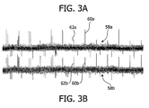
- Fig. 3A illustrates a trace of a signal derived from an optical disc during read mode in accordance with the prior-art.
- the centre of the trace 58a represents the wobble signal and the signal spikes 60a and 62a represent LPP signals produced by means of the LPPs of the disc.
- the readily discernable LPP signal 60a is that arising from a LPP located adjacent a long space of the disc.
- the LPP signal 62a of small amplitude, and which is almost lost amongst the wobble signal, is that arising when the LPP is located adjacent a relatively long mark of the disc.
- a corresponding signal derived in accordance with the present invention is illustrated and which again shows a central wobble signal 58B.
- both LPP signals 60b and 62b are readily discernible for both the LPP that is located adjacent the relatively long mark, and that is adjacent a relatively long space on the optical disc.
Landscapes
- Optical Recording Or Reproduction (AREA)
- Radar Systems Or Details Thereof (AREA)
- Measurement Of Velocity Or Position Using Acoustic Or Ultrasonic Waves (AREA)
- Hardware Redundancy (AREA)
Abstract
Description
- The present invention relates to a Land Pre-Pit (LPP) signal processing method and related apparatus.
- Recordable optical discs such as DVD-R and DVD-RW discs are arranged to provide for a LPP signal, which is used primarily for the detection of disc-addressing information and for providing other auxiliary data.
- The LPP signal is produced by means of a Land Pre-Pit, which comprises a microstructure embossed at predetermined positions along a land of an optical disc. In current DVD-R and DVD-RW recording systems, the LPP signal is employed during reading from the disc both before and after recording and so as, for example, to confirm the physical address at which data blocks have been written.
- However, it has been found that the quality of the LPP signal when data is being read from the disc is disadvantageously limited primarily due to High Frequency (HF) crosstalk arising from the adjacent lands and grooves which, as is known, are arranged to provide for a so-called wobble signal serving to assist with tracking of the optical head of the optical disc drive during recording and playback.
- Further, while recording arrangements such as the provision of a push-pull signal normalised on the Radio Frequency (RF) analogue signal can serve to improve the LPP signal within a limited range there is nevertheless a disadvantageous inherent lack of flexibility. Limitations of such techniques within the recording system can further disadvantageously provide a "divided by zero" problem if the offset for the HF crosstalk signal is not appropriately set.
- A further disadvantage that arises is that fast-normalisation proves problematic to implement within the digital domain.
- A further disadvantage that arises is that fast-normalisation proves problematic to implement within the digital domain.
-
EP-A-1 225 570 discloses a pre-pit detecting apparatus wherein first and second read signals generated on the basis of the outputs of electrical signals from a light receiving portion are input to an amplitude correcting circuit, the first and second read signals are added to generate an addition signal. Then the amplitudes of the first and second read signals are corrected for the each RF signal component corresponding to each recording pit, which is contained in the first and second read signals on the basis of the addition signal. Finally, the difference between the first and second read signals is computed to generate a difference signal so that a pre-pit signal will be detected on the basis of the difference signal. - The present invention seeks to provide for an LPP signal processing method and related apparatus having advantages over known such methods and apparatus.
- According to a first aspect of the present invention, there is provided a method of producing a Land Pre-Pit signal during playback of an optical disc and comprising the steps of:
- obtaining an output signal from an optical detector and from which the Land Pre-Pit signal is to be derived;
- scaling the said output signal responsive to a determined amplitude of a high frequency crosstalk signal arising during reading of the disc and in a manner so as to increase the said output signal when the Land Pre-Pit is identified as corresponding to a mark on the disc, and so as to decrease the output signal when the Land Pre-Pit is identified as corresponding to a space on the disc,;
- characterised in that said output signal comprises a balanced push-pull signal.
- The invention is advantageous in accurately boosting a small LPP signal, but alternatively attenuating the LPP signal when appropriate. The rescaling of the LPP signal based on the amplitude of the HF crosstalk signal advantageously allows for such boosting and attenuation.
- The invention therefore advantageously can provide for an offset - independent re-scaling process and which serves to reduce the error rate and/or standard deviation commonly arising in the LPP signal.
- Preferably, the balanced push-pull signal is derived from the difference between a high pass filtered push-pull signal from the optical detector and a high pass filtered high frequency crosstalk signal.
- Advantageously, LPP waveform width changes can be compensated by means of a sample-rate-converter.
- The method is further advantageous in calculating the LPP signal by means of convolution of push-pull signal along with a LPP-like wavelet.
- Further, the scaling factor applied to the said output signal can be fine-tuned by means of a standard deviation step serving to calculate an error rate within the LPP signal.
- According to another aspect of the present invention, there is provided a LPP signal processing apparatus arranged for producing a LPP signal during playback of an optical disc and comprising:
- means for obtaining an output signal from an optical detector and from which the LPP signal is to be derived;
- means for scaling the said output signal responsive to a determined amplitude of a high frequency crosstalk signal arising during reading of the disc and in a manner so as to increase the said output signal when the Land Pre-Pit is identified as corresponding to a mark on the disc, and so as to decrease the output signal when the Land Pre-Pit is identified as corresponding to a space on the disc;
- characterised in that said output signal comprises a balanced push-pull signal.
- Further features can advantageously be provided such that the apparatus can provide for the further advantages discussed above in relation to the discussion of the method of the present invention.
- As discussed, the method and apparatus of the present invention is particular advantageous in reducing the error rate or standard deviation within
- Turning now to
Fig. 1 , there is illustrated a section through part of anoptical disc 10 to which data can be written and which comprises a spiral ofgrooves 12 upon whichdata marks 14 are written by means of an optical read/write head (not shown) and whichgrooves 12 are separated byspiral lands 16. As will be seen, the upper edges of thelands 16 are formed with a sinusoidal configuration which is arranged to provide for a so-called wobble signal. This signal is arranged to be detected by the optical read/write head and is employed to assist with the accurate tracking of the optical read/write head and as is well known and so is not described further here. - Within the
land 16 are illustrated two Land Pre-Pits (LPP) 18,20 which comprise embossed structures provided within theland 16 and which form part of a pre-formatting addressing scheme arranged for identifying physical addresses on the disc where data blocks are to be, or have been, written. - Thus, when reading a disc, in addition to encountering the
data mark 14, and the sinusoidal configurations of the upper edges of thelands 16, an output signal is also produced when the optical read/write head encounters eachLPP - It has however been identified, in particular due to HF crosstalk produced by the disc, that the signal developed from the LPP, i.e. so-called LPP signal, can prove difficult to detect particularly when the LPP is located adjacent a long data mark which will exhibit a low light-reflection characteristic. Such problems do not however arise when a LPP located adjacent a relatively long space on the disc.
- Within the present invention, a method and arrangement is provided whereby the amplitude of the LPP signal when located adjacent a mark is increased. Likewise, its amplitude can be decreased through attenuation when it is identified that the LPP is located adjacent a space.
- Such re-scaling of the LPP signal advantageously is based advantageously upon the amplitude of the HF crosstalk signal encountered when reading from a disc.
- With regard to
Fig. 2 therefore, there is illustrated an example of an arrangement for providing the advantageous LPP processing of the present invention. - The
arrangement 22 comprises identical first 24, and second 26, high pass filters which are further arranged to high pass filter the high frequencycross talk signals 28 and push-pull signals 30 derived from the optical read/write head (not shown). - The output of the high pass filtered push-
pull signal 30 is then delivered to thedifference unit 32 arranged to produce a balanced push-pull signal 34. The balanced push-pull signal 34 is delivered to amultiplier 36 where it is combined with the high pass filteredcross talk signal 28 and delivered to an arrangement for determining a coefficient which is likewise to be applied to the high pass filteredcross talk signal 28 before delivery to thedifference unit 32. - In the illustrated embodiment, the coefficient (COEF) is determined by an integrate and
dump unit 38 arranged to receive the output from themultiplier 36 and to deliver a signal to aPI controller 40. However, it should be appreciated that, as an alternative, a low-pass filter could be employed in place of the integrate anddump unit 38. It is noted that the sign bit of theHF crosstalk signal 28 can be employed to simplify the aforementioned multiplication atmultiplier 36. - The above-mentioned coefficient derived from the
PI controller 40 is, as noted, applied to the high pass filteredcrosstalk signal 28 and the result delivered to thedifference unit 32 from which the balanced push-pull signal 34 is derived. - A peak and
bottom detector unit 42 is arranged to receive the output from thehigh pass filter 24, i.e. the high pass filteredcrosstalk signal 28, and so as to detect the peak, and the bottom, of the high pass filteredcrosstalk signal 28. The output from thisdetector unit 42 is employed in turn to control the scaling factor to be applied to the balanced push-pull signal 34 by means of a scalingfactor selection unit 44. - As illustrated in
Fig. 2 , the scalingfactor selection unit 44 applies a scaling factor signal to the balanced push-pull signal 34 at amultiplier 46 and the output of the multiplier is delivered in turn to asample rate converter 48. - The
sample rate converter 48 is advantageously employed to compensate the LPP waveform with changes that can arise in a Constant Angular Velocity (CAV) system. The signal then derived is arranged to produce the final LPP signal by means of aconvolution unit 50 arranged for convolution of the rescaled balanced push-pull signal and a LPP-like wavelet W in which the wavelet W represents an ideal waveform for the LPP signal. The overall length of the wavelet illustrated by Wk is advantageously determined by the sampling rate, and recording speed, of the optical disc drive system. - As noted, the result of the convolution is output as the required
LPP signal 52, which in turn is advantageously delivered to LPP detection andstandard deviation unit 54. A signal can be derived from the LPP detection andstandard deviation unit 54 and employed by means of adigital signal processor 56, or other appropriate digital hardware. This serves to provide for a fine tuning signal which can be applied to the scalingfactor selection unit 44 so as to fine tune the scaling factor applied to the high pass filtered push-pull signal 34 at themultiplier 46. The LPP detection andstandard deviation unit 54 is advantageously arranged to calculate an error rate within theLPP signal 52 so as to provide for such fine-tuning. - The scaling
factor selection unit 44 operates such that the greater the amplitude of the highfrequency crosstalk signal 28, the smaller the scaling factor that is applied to the balanced push-pull signal 34. - As will therefore be appreciated, in the illustrated embodiment, the balanced push-pull signal is rescaled based upon the amplitude of the HF crosstalk signal such that a relatively small LPP signal adjacent a long mark on the disc will be boosted while a relatively large LPP signal located adjacent a long space on the disc will be attenuated.
- The aforementioned fine-tuning of the scaling factor enhances the flexibility of the method and arrangement and is advantageously offset-independent.
- Also, the "divided by zero" problem encountered within the prior-art advantageously does not arise.
- The error rate, or standard deviation, of the LPP signal is advantageously significantly reduced in accordance with the present invention.
- As a further illustration of the advantageous reduction in the error rate of the LPP detection in read mode in accordance with the present invention, reference is now made to
Figs. 3A and 3B . -
Fig. 3A , illustrates a trace of a signal derived from an optical disc during read mode in accordance with the prior-art. The centre of thetrace 58a represents the wobble signal and the signal spikes 60a and 62a represent LPP signals produced by means of the LPPs of the disc. - The readily
discernable LPP signal 60a is that arising from a LPP located adjacent a long space of the disc. TheLPP signal 62a of small amplitude, and which is almost lost amongst the wobble signal, is that arising when the LPP is located adjacent a relatively long mark of the disc. - Turning now to
Fig. 3B , a corresponding signal derived in accordance with the present invention is illustrated and which again shows a central wobble signal 58B. However, in view of the signal boosting and signal attenuation discussed above, it will be appreciated that both LPP signals 60b and 62b are readily discernible for both the LPP that is located adjacent the relatively long mark, and that is adjacent a relatively long space on the optical disc. - In view of the manner in which it is now possible to readily differentiate the LPP signals from the wobble signal, it will be appreciated that the error rate associated with the LPP signal, particularly in read mode, is advantageously greatly reduced.
Claims (16)
- A method of producing a Land Pre-Pit signal during playback of an optical disc and comprising the steps of:obtaining an output signal from an optical detector and from which the Land Pre-Pit signal is to be derived;scaling the said output signal responsive to a determined amplitude of a high frequency crosstalk signal arising during reading of the disc and in a manner so as to increase the said output signal when the Land Pre-Pit is identified as adjacent to a mark on the disc, and so as to decrease the output signal when the Land Pre-Pit is identified as adjacent to a space on the disc.characterised in that said output signal comprises a balanced push-pull signal.
- A method as claimed in Claim 1, wherein the balanced push-pull signal is derived from the difference between a high pass filtered push-pull signal and a high-pass filtered high frequency crosstalk signal.
- A method as claimed in Claim 1 or 2, and including the step of compensating for LPP signal width changes.
- A method as claimed in Claim 3, wherein the said compensation is achieved by way of a sample rate conversion step.
- A method as claimed in any one or more of Claims 1-4, wherein the LPP signal is calculated by means of a convolution step based on the rescaled output signal.
- A method as claimed in Claim 5, wherein the convolution step includes a LPP-like wavelet.
- A method as claimed in any one or more of the preceding claims, including the step of calculating an error rate in the LPP signal and processing the error rate so as to fine-tune the scaling of the said output signal.
- A method as claimed in Claim 7, wherein the calculation of the error rate is based on the standard deviation of the LPP signal.
- An LPP signal processing apparatus arranged for producing a LPP signal during playback of an optical disc and comprising:means for obtaining an output signal from an optical detector and from which the LPP signal is to be derived;means for scaling the said output signal responsive to a determined amplitude of a high frequency crosstalk signal arising during reading of the disc and in a manner so as to increase the said output signal when the Land Pre-Pit is identified as corresponding to a mark on the disc, and so as to decrease the output signal when the Land Pre-Pit is identified as corresponding to a space on the disc;characterised in that said output signal comprises a balanced push-pull signal.
- An apparatus as claimed in Claim 9, wherein the balanced push-pull signal is derived from the difference between a high pass filtered push-pull signal and a high-pass filtered high frequency crosstalk signal.
- An apparatus as claimed in Claims 10 or 11, and including means for compensating for LPP signal width changes.
- An apparatus as claimed in Claim 11, wherein the said means for compensating is arranged to provide for sample rate conversation.
- An apparatus as claimed in any one or more of Claims 9-12, and including means for calculating the LPP signal by means of a convolution step based on the rescaled output signal.
- An apparatus as claimed in Claim 13, wherein the convolution step includes a LPP-like wavelet.
- Ah apparatus as claimed in any one or more of the preceding claims, including means for calculating an error rate in the LPP signal and processing the error rate so as to fine-tune the scaling of the said output signal.
- An apparatus as claimed in Claim 15, wherein the means for calculating the error rate is arranged to apply a standard deviation technique to the LPP signal.
Applications Claiming Priority (2)
| Application Number | Priority Date | Filing Date | Title |
|---|---|---|---|
| GBGB0413647.9A GB0413647D0 (en) | 2004-06-18 | 2004-06-18 | Land pre-pit signal processing method and related apparatus |
| PCT/IB2005/051834 WO2005124744A1 (en) | 2004-06-18 | 2005-06-06 | Land pre-pit signal processing method and related apparatus |
Publications (3)
| Publication Number | Publication Date |
|---|---|
| EP1761919A1 EP1761919A1 (en) | 2007-03-14 |
| EP1761919B1 true EP1761919B1 (en) | 2008-04-30 |
| EP1761919B9 EP1761919B9 (en) | 2009-08-12 |
Family
ID=32750147
Family Applications (1)
| Application Number | Title | Priority Date | Filing Date |
|---|---|---|---|
| EP05744768A Expired - Lifetime EP1761919B9 (en) | 2004-06-18 | 2005-06-06 | Land pre-pit signal processing method and related apparatus |
Country Status (8)
| Country | Link |
|---|---|
| US (1) | US7796482B2 (en) |
| EP (1) | EP1761919B9 (en) |
| JP (1) | JP2008503020A (en) |
| CN (1) | CN100476961C (en) |
| AT (1) | ATE393954T1 (en) |
| DE (1) | DE602005006416T2 (en) |
| GB (1) | GB0413647D0 (en) |
| WO (1) | WO2005124744A1 (en) |
Family Cites Families (17)
| Publication number | Priority date | Publication date | Assignee | Title |
|---|---|---|---|---|
| JP3968193B2 (en) * | 1999-04-26 | 2007-08-29 | パイオニア株式会社 | Pre-pit detection device |
| JP2002216354A (en) * | 2001-01-15 | 2002-08-02 | Pioneer Electronic Corp | Pre-pit detection device |
| JP4408188B2 (en) * | 2001-01-15 | 2010-02-03 | パイオニア株式会社 | Pre-pit detection device and binarization level setting method |
| JP2003091932A (en) * | 2001-09-17 | 2003-03-28 | Teac Corp | Signal processing circuit |
| KR100484131B1 (en) * | 2001-12-04 | 2005-04-18 | 삼성전자주식회사 | Method and apparatus for detecting address information recorded on an optical disc by pre-pit |
| JP2004079030A (en) * | 2002-08-12 | 2004-03-11 | Sony Corp | Disk drive device, address detection method |
| JP2004134002A (en) * | 2002-10-10 | 2004-04-30 | Sony Corp | Disk drive device, pre-pit detection method |
| JP4598355B2 (en) * | 2002-10-10 | 2010-12-15 | ソニー株式会社 | Disk drive device and pre-pit detection method |
| EP1477985A1 (en) * | 2003-05-14 | 2004-11-17 | Deutsche Thomson-Brandt Gmbh | Method and device for detecting land pre-pits |
| DE602004014217D1 (en) * | 2003-06-10 | 2008-07-17 | Thomson Licensing | Procedure for the recovery of land pre-well |
| JP4357890B2 (en) * | 2003-08-08 | 2009-11-04 | パイオニア株式会社 | Land pre-pit detection apparatus and method |
| KR20050019622A (en) * | 2003-08-20 | 2005-03-03 | 삼성전자주식회사 | Land pre-pit data detection apparatus and method thereof |
| JP3831366B2 (en) * | 2003-08-27 | 2006-10-11 | シナノケンシ株式会社 | LPP signal detection method and optical disc apparatus |
| JP2005078686A (en) * | 2003-08-29 | 2005-03-24 | Shinano Kenshi Co Ltd | Lpp signal detection method and optical disk unit |
| JP2005158168A (en) * | 2003-11-27 | 2005-06-16 | Pioneer Electronic Corp | Information reading device and prepit detecting circuit |
| US7079475B2 (en) * | 2003-12-05 | 2006-07-18 | Ricoh Company, Ltd. | Pre-pit information-detecting apparatus, optical-information detecting apparatus, program, and computer-readable information-recording medium |
| KR100594739B1 (en) * | 2004-01-19 | 2006-06-30 | 삼성전자주식회사 | Pre-pit signal detection device and method |
-
2004
- 2004-06-18 GB GBGB0413647.9A patent/GB0413647D0/en not_active Ceased
-
2005
- 2005-06-06 JP JP2007516088A patent/JP2008503020A/en not_active Withdrawn
- 2005-06-06 EP EP05744768A patent/EP1761919B9/en not_active Expired - Lifetime
- 2005-06-06 US US11/630,093 patent/US7796482B2/en active Active
- 2005-06-06 WO PCT/IB2005/051834 patent/WO2005124744A1/en not_active Ceased
- 2005-06-06 DE DE602005006416T patent/DE602005006416T2/en not_active Expired - Lifetime
- 2005-06-06 CN CNB2005800200562A patent/CN100476961C/en not_active Expired - Fee Related
- 2005-06-06 AT AT05744768T patent/ATE393954T1/en not_active IP Right Cessation
Also Published As
| Publication number | Publication date |
|---|---|
| CN1969327A (en) | 2007-05-23 |
| WO2005124744A1 (en) | 2005-12-29 |
| EP1761919A1 (en) | 2007-03-14 |
| CN100476961C (en) | 2009-04-08 |
| ATE393954T1 (en) | 2008-05-15 |
| DE602005006416T2 (en) | 2009-06-04 |
| GB0413647D0 (en) | 2004-07-21 |
| US7796482B2 (en) | 2010-09-14 |
| US20080031122A1 (en) | 2008-02-07 |
| EP1761919B9 (en) | 2009-08-12 |
| JP2008503020A (en) | 2008-01-31 |
| DE602005006416D1 (en) | 2008-06-12 |
Similar Documents
| Publication | Publication Date | Title |
|---|---|---|
| US6785207B2 (en) | Wobble signal reproducing circuit | |
| US6754157B2 (en) | Recording and/or reproducing apparatus and recording and/or reproducing method capable of detecting a land pre-pit on disc securely at a high precision | |
| US6707780B2 (en) | Prepit detecting apparatus | |
| US6466533B2 (en) | Prepit detection unit | |
| US6888783B2 (en) | Wobble detection circuit corresponding to a plurality of media having different pre-formats and optical disk apparatus having reduced size | |
| EP1067525B1 (en) | Method and apparatus for tracking error detection in optical disk driver | |
| US7187629B2 (en) | Method and related apparatus for deriving a tracking error signal | |
| EP1761919B9 (en) | Land pre-pit signal processing method and related apparatus | |
| US7636278B2 (en) | Information recording system and an information recording method | |
| US7428204B2 (en) | Method for recording address information on optical recording medium, optical recording medium including address information recorded thereon by the same method, and method for detecting address information recorded on the same optical recording medium | |
| EP1619676A1 (en) | Optical disc device, circuit for optical disc device, wobble signal reproduction method, and land pre-pit signal reproduction method | |
| EP1759385B1 (en) | Method and apparatus for writing data to an optical disc | |
| US20030086344A1 (en) | Apparatus and method for slicing a pre-pit signal | |
| JP3355826B2 (en) | Tracking error detection method and device | |
| JP2006079730A (en) | Optical disk device | |
| KR20070028550A (en) | Recording system with improved prepit detection | |
| JP2001236650A (en) | Optical disk recorder | |
| JP2003059054A (en) | Optical disk recording/reproducing device | |
| JP2005149589A (en) | Optical disk device | |
| JP2003257050A (en) | Track cross signal generation circuit |
Legal Events
| Date | Code | Title | Description |
|---|---|---|---|
| PUAI | Public reference made under article 153(3) epc to a published international application that has entered the european phase |
Free format text: ORIGINAL CODE: 0009012 |
|
| 17P | Request for examination filed |
Effective date: 20070118 |
|
| AK | Designated contracting states |
Kind code of ref document: A1 Designated state(s): AT BE BG CH CY CZ DE DK EE ES FI FR GB GR HU IE IS IT LI LT LU MC NL PL PT RO SE SI SK TR |
|
| 17Q | First examination report despatched |
Effective date: 20070522 |
|
| RAP1 | Party data changed (applicant data changed or rights of an application transferred) |
Owner name: NXP B.V. |
|
| DAX | Request for extension of the european patent (deleted) | ||
| GRAP | Despatch of communication of intention to grant a patent |
Free format text: ORIGINAL CODE: EPIDOSNIGR1 |
|
| GRAS | Grant fee paid |
Free format text: ORIGINAL CODE: EPIDOSNIGR3 |
|
| GRAA | (expected) grant |
Free format text: ORIGINAL CODE: 0009210 |
|
| AK | Designated contracting states |
Kind code of ref document: B1 Designated state(s): AT BE BG CH CY CZ DE DK EE ES FI FR GB GR HU IE IS IT LI LT LU MC NL PL PT RO SE SI SK TR |
|
| REG | Reference to a national code |
Ref country code: GB Ref legal event code: FG4D |
|
| REG | Reference to a national code |
Ref country code: CH Ref legal event code: EP |
|
| REG | Reference to a national code |
Ref country code: IE Ref legal event code: FG4D Free format text: LANGUAGE OF EP DOCUMENT: FRENCH |
|
| REF | Corresponds to: |
Ref document number: 602005006416 Country of ref document: DE Date of ref document: 20080612 Kind code of ref document: P |
|
| PG25 | Lapsed in a contracting state [announced via postgrant information from national office to epo] |
Ref country code: SI Free format text: LAPSE BECAUSE OF FAILURE TO SUBMIT A TRANSLATION OF THE DESCRIPTION OR TO PAY THE FEE WITHIN THE PRESCRIBED TIME-LIMIT Effective date: 20080430 |
|
| NLV1 | Nl: lapsed or annulled due to failure to fulfill the requirements of art. 29p and 29m of the patents act | ||
| PG25 | Lapsed in a contracting state [announced via postgrant information from national office to epo] |
Ref country code: FI Free format text: LAPSE BECAUSE OF FAILURE TO SUBMIT A TRANSLATION OF THE DESCRIPTION OR TO PAY THE FEE WITHIN THE PRESCRIBED TIME-LIMIT Effective date: 20080430 Ref country code: BG Free format text: LAPSE BECAUSE OF FAILURE TO SUBMIT A TRANSLATION OF THE DESCRIPTION OR TO PAY THE FEE WITHIN THE PRESCRIBED TIME-LIMIT Effective date: 20080730 Ref country code: ES Free format text: LAPSE BECAUSE OF FAILURE TO SUBMIT A TRANSLATION OF THE DESCRIPTION OR TO PAY THE FEE WITHIN THE PRESCRIBED TIME-LIMIT Effective date: 20080810 Ref country code: PT Free format text: LAPSE BECAUSE OF FAILURE TO SUBMIT A TRANSLATION OF THE DESCRIPTION OR TO PAY THE FEE WITHIN THE PRESCRIBED TIME-LIMIT Effective date: 20080930 Ref country code: NL Free format text: LAPSE BECAUSE OF FAILURE TO SUBMIT A TRANSLATION OF THE DESCRIPTION OR TO PAY THE FEE WITHIN THE PRESCRIBED TIME-LIMIT Effective date: 20080430 |
|
| PG25 | Lapsed in a contracting state [announced via postgrant information from national office to epo] |
Ref country code: PL Free format text: LAPSE BECAUSE OF FAILURE TO SUBMIT A TRANSLATION OF THE DESCRIPTION OR TO PAY THE FEE WITHIN THE PRESCRIBED TIME-LIMIT Effective date: 20080430 Ref country code: AT Free format text: LAPSE BECAUSE OF FAILURE TO SUBMIT A TRANSLATION OF THE DESCRIPTION OR TO PAY THE FEE WITHIN THE PRESCRIBED TIME-LIMIT Effective date: 20080430 |
|
| PG25 | Lapsed in a contracting state [announced via postgrant information from national office to epo] |
Ref country code: IS Free format text: LAPSE BECAUSE OF FAILURE TO SUBMIT A TRANSLATION OF THE DESCRIPTION OR TO PAY THE FEE WITHIN THE PRESCRIBED TIME-LIMIT Effective date: 20080830 |
|
| ET | Fr: translation filed | ||
| PG25 | Lapsed in a contracting state [announced via postgrant information from national office to epo] |
Ref country code: LT Free format text: LAPSE BECAUSE OF FAILURE TO SUBMIT A TRANSLATION OF THE DESCRIPTION OR TO PAY THE FEE WITHIN THE PRESCRIBED TIME-LIMIT Effective date: 20080430 Ref country code: CZ Free format text: LAPSE BECAUSE OF FAILURE TO SUBMIT A TRANSLATION OF THE DESCRIPTION OR TO PAY THE FEE WITHIN THE PRESCRIBED TIME-LIMIT Effective date: 20080430 Ref country code: DK Free format text: LAPSE BECAUSE OF FAILURE TO SUBMIT A TRANSLATION OF THE DESCRIPTION OR TO PAY THE FEE WITHIN THE PRESCRIBED TIME-LIMIT Effective date: 20080430 Ref country code: MC Free format text: LAPSE BECAUSE OF NON-PAYMENT OF DUE FEES Effective date: 20080630 Ref country code: SE Free format text: LAPSE BECAUSE OF FAILURE TO SUBMIT A TRANSLATION OF THE DESCRIPTION OR TO PAY THE FEE WITHIN THE PRESCRIBED TIME-LIMIT Effective date: 20080731 |
|
| PG25 | Lapsed in a contracting state [announced via postgrant information from national office to epo] |
Ref country code: BE Free format text: LAPSE BECAUSE OF FAILURE TO SUBMIT A TRANSLATION OF THE DESCRIPTION OR TO PAY THE FEE WITHIN THE PRESCRIBED TIME-LIMIT Effective date: 20080430 Ref country code: SK Free format text: LAPSE BECAUSE OF FAILURE TO SUBMIT A TRANSLATION OF THE DESCRIPTION OR TO PAY THE FEE WITHIN THE PRESCRIBED TIME-LIMIT Effective date: 20080430 Ref country code: RO Free format text: LAPSE BECAUSE OF FAILURE TO SUBMIT A TRANSLATION OF THE DESCRIPTION OR TO PAY THE FEE WITHIN THE PRESCRIBED TIME-LIMIT Effective date: 20080430 |
|
| PLBE | No opposition filed within time limit |
Free format text: ORIGINAL CODE: 0009261 |
|
| STAA | Information on the status of an ep patent application or granted ep patent |
Free format text: STATUS: NO OPPOSITION FILED WITHIN TIME LIMIT |
|
| REG | Reference to a national code |
Ref country code: IE Ref legal event code: MM4A |
|
| 26N | No opposition filed |
Effective date: 20090202 |
|
| REG | Reference to a national code |
Ref country code: FR Ref legal event code: ST Effective date: 20090228 |
|
| PG25 | Lapsed in a contracting state [announced via postgrant information from national office to epo] |
Ref country code: IE Free format text: LAPSE BECAUSE OF NON-PAYMENT OF DUE FEES Effective date: 20080606 Ref country code: EE Free format text: LAPSE BECAUSE OF FAILURE TO SUBMIT A TRANSLATION OF THE DESCRIPTION OR TO PAY THE FEE WITHIN THE PRESCRIBED TIME-LIMIT Effective date: 20080430 |
|
| REG | Reference to a national code |
Ref country code: FR Ref legal event code: D3 |
|
| PG25 | Lapsed in a contracting state [announced via postgrant information from national office to epo] |
Ref country code: IT Free format text: LAPSE BECAUSE OF FAILURE TO SUBMIT A TRANSLATION OF THE DESCRIPTION OR TO PAY THE FEE WITHIN THE PRESCRIBED TIME-LIMIT Effective date: 20080430 Ref country code: FR Free format text: LAPSE BECAUSE OF NON-PAYMENT OF DUE FEES Effective date: 20080630 |
|
| REG | Reference to a national code |
Ref country code: CH Ref legal event code: PL |
|
| PG25 | Lapsed in a contracting state [announced via postgrant information from national office to epo] |
Ref country code: LI Free format text: LAPSE BECAUSE OF NON-PAYMENT OF DUE FEES Effective date: 20090630 Ref country code: CH Free format text: LAPSE BECAUSE OF NON-PAYMENT OF DUE FEES Effective date: 20090630 |
|
| PG25 | Lapsed in a contracting state [announced via postgrant information from national office to epo] |
Ref country code: LU Free format text: LAPSE BECAUSE OF NON-PAYMENT OF DUE FEES Effective date: 20080606 Ref country code: HU Free format text: LAPSE BECAUSE OF FAILURE TO SUBMIT A TRANSLATION OF THE DESCRIPTION OR TO PAY THE FEE WITHIN THE PRESCRIBED TIME-LIMIT Effective date: 20081101 Ref country code: CY Free format text: LAPSE BECAUSE OF FAILURE TO SUBMIT A TRANSLATION OF THE DESCRIPTION OR TO PAY THE FEE WITHIN THE PRESCRIBED TIME-LIMIT Effective date: 20080430 |
|
| PG25 | Lapsed in a contracting state [announced via postgrant information from national office to epo] |
Ref country code: TR Free format text: LAPSE BECAUSE OF FAILURE TO SUBMIT A TRANSLATION OF THE DESCRIPTION OR TO PAY THE FEE WITHIN THE PRESCRIBED TIME-LIMIT Effective date: 20080430 |
|
| PG25 | Lapsed in a contracting state [announced via postgrant information from national office to epo] |
Ref country code: GR Free format text: LAPSE BECAUSE OF FAILURE TO SUBMIT A TRANSLATION OF THE DESCRIPTION OR TO PAY THE FEE WITHIN THE PRESCRIBED TIME-LIMIT Effective date: 20080731 |
|
| REG | Reference to a national code |
Ref country code: GB Ref legal event code: 732E Free format text: REGISTERED BETWEEN 20121108 AND 20121114 |
|
| REG | Reference to a national code |
Ref country code: DE Ref legal event code: R082 Ref document number: 602005006416 Country of ref document: DE Representative=s name: MUELLER-BORE & PARTNER PATENTANWAELTE, EUROPEA, DE |
|
| REG | Reference to a national code |
Ref country code: DE Ref legal event code: R081 Ref document number: 602005006416 Country of ref document: DE Owner name: CALLAHAN CELLULAR L.L.C., US Free format text: FORMER OWNER: NXP B.V., EINDHOVEN, NL Effective date: 20130211 Ref country code: DE Ref legal event code: R082 Ref document number: 602005006416 Country of ref document: DE Representative=s name: MUELLER-BORE & PARTNER PATENTANWAELTE, EUROPEA, DE Effective date: 20130211 Ref country code: DE Ref legal event code: R082 Ref document number: 602005006416 Country of ref document: DE Representative=s name: MUELLER-BORE & PARTNER PATENTANWAELTE PARTG MB, DE Effective date: 20130211 Ref country code: DE Ref legal event code: R081 Ref document number: 602005006416 Country of ref document: DE Owner name: CALLAHAN CELLULAR L.L.C., WILMINGTON, US Free format text: FORMER OWNER: NXP B.V., EINDHOVEN, NL Effective date: 20130211 |
|
| REG | Reference to a national code |
Ref country code: FR Ref legal event code: TP Owner name: CALLAHAN CELLULAR L.L.C., US Effective date: 20130724 |
|
| PGRI | Patent reinstated in contracting state [announced from national office to epo] |
Ref country code: FR Effective date: 20090420 |
|
| PGFP | Annual fee paid to national office [announced via postgrant information from national office to epo] |
Ref country code: DE Payment date: 20140630 Year of fee payment: 10 |
|
| REG | Reference to a national code |
Ref country code: DE Ref legal event code: R119 Ref document number: 602005006416 Country of ref document: DE |
|
| PG25 | Lapsed in a contracting state [announced via postgrant information from national office to epo] |
Ref country code: DE Free format text: LAPSE BECAUSE OF NON-PAYMENT OF DUE FEES Effective date: 20160101 |
|
| REG | Reference to a national code |
Ref country code: FR Ref legal event code: PLFP Year of fee payment: 12 |
|
| REG | Reference to a national code |
Ref country code: FR Ref legal event code: PLFP Year of fee payment: 13 |
|
| REG | Reference to a national code |
Ref country code: FR Ref legal event code: PLFP Year of fee payment: 14 |
|
| PGFP | Annual fee paid to national office [announced via postgrant information from national office to epo] |
Ref country code: FR Payment date: 20210520 Year of fee payment: 17 |
|
| PGFP | Annual fee paid to national office [announced via postgrant information from national office to epo] |
Ref country code: GB Payment date: 20210528 Year of fee payment: 17 |
|
| GBPC | Gb: european patent ceased through non-payment of renewal fee |
Effective date: 20220606 |
|
| PG25 | Lapsed in a contracting state [announced via postgrant information from national office to epo] |
Ref country code: FR Free format text: LAPSE BECAUSE OF NON-PAYMENT OF DUE FEES Effective date: 20220630 |
|
| PG25 | Lapsed in a contracting state [announced via postgrant information from national office to epo] |
Ref country code: GB Free format text: LAPSE BECAUSE OF NON-PAYMENT OF DUE FEES Effective date: 20220606 |