EP1761887B1 - Non-demolition photon detector that preserves input state characteristics - Google Patents
Non-demolition photon detector that preserves input state characteristics Download PDFInfo
- Publication number
- EP1761887B1 EP1761887B1 EP05741090.4A EP05741090A EP1761887B1 EP 1761887 B1 EP1761887 B1 EP 1761887B1 EP 05741090 A EP05741090 A EP 05741090A EP 1761887 B1 EP1761887 B1 EP 1761887B1
- Authority
- EP
- European Patent Office
- Prior art keywords
- state
- photon
- eit
- matter
- probe
- Prior art date
- Legal status (The legal status is an assumption and is not a legal conclusion. Google has not performed a legal analysis and makes no representation as to the accuracy of the status listed.)
- Expired - Lifetime
Links
Images


Classifications
-
- G—PHYSICS
- G01—MEASURING; TESTING
- G01J—MEASUREMENT OF INTENSITY, VELOCITY, SPECTRAL CONTENT, POLARISATION, PHASE OR PULSE CHARACTERISTICS OF INFRARED, VISIBLE OR ULTRAVIOLET LIGHT; COLORIMETRY; RADIATION PYROMETRY
- G01J1/00—Photometry, e.g. photographic exposure meter
- G01J1/42—Photometry, e.g. photographic exposure meter using electric radiation detectors
- G01J1/44—Electric circuits
-
- G—PHYSICS
- G06—COMPUTING OR CALCULATING; COUNTING
- G06N—COMPUTING ARRANGEMENTS BASED ON SPECIFIC COMPUTATIONAL MODELS
- G06N10/00—Quantum computing, i.e. information processing based on quantum-mechanical phenomena
- G06N10/40—Physical realisations or architectures of quantum processors or components for manipulating qubits, e.g. qubit coupling or qubit control
-
- B—PERFORMING OPERATIONS; TRANSPORTING
- B82—NANOTECHNOLOGY
- B82Y—SPECIFIC USES OR APPLICATIONS OF NANOSTRUCTURES; MEASUREMENT OR ANALYSIS OF NANOSTRUCTURES; MANUFACTURE OR TREATMENT OF NANOSTRUCTURES
- B82Y10/00—Nanotechnology for information processing, storage or transmission, e.g. quantum computing or single electron logic
-
- G—PHYSICS
- G01—MEASURING; TESTING
- G01J—MEASUREMENT OF INTENSITY, VELOCITY, SPECTRAL CONTENT, POLARISATION, PHASE OR PULSE CHARACTERISTICS OF INFRARED, VISIBLE OR ULTRAVIOLET LIGHT; COLORIMETRY; RADIATION PYROMETRY
- G01J1/00—Photometry, e.g. photographic exposure meter
- G01J1/42—Photometry, e.g. photographic exposure meter using electric radiation detectors
- G01J1/44—Electric circuits
- G01J2001/4446—Type of detector
- G01J2001/446—Photodiode
- G01J2001/4466—Avalanche
Definitions
- Quantum processors having tens or hundreds of qubits, for example, would be able to perform quantum simulations unreachable with any classical machine. Such quantum processors also have the potential to extend the working distances and applicability of quantum communications:
- Proposed quantum information systems that use photon states often require detectors capable of efficiently detecting the presence or absence of one or a few photons.
- a miscount of the number of photons or a failure to detect the presence of a photon causes an inaccurate measurement of the photon state and an error in evaluation of the quantum information.
- Such errors when tolerable, require error correction schemes that may be expensive to implement.
- the photoelectric current from a single photon is small and difficult to detect.
- the best commercial photon detectors for visible light currently have a quantum efficiency of about 90% for detecting single photons, and the efficiency achieved in practice is much lower.
- detectors for single photons having wavelengths between 1.3 and 1.5 ⁇ m are only about 30% efficient. These efficiencies are too low for many quantum information systems.
- the best efficiencies achieved for the visible-spectrum photon detectors require cooling the detectors down to about 6 °K, and such detectors still provide relatively high "dark count" rates (e.g., high background noise when no photon is incident.)
- quantum information systems require photon detectors that are highly efficient at detecting photons and that can accurately distinguish the number of photons in a quantum signal.
- the detectors would be non-destructive, so that after the presence or number of photons has been inferred, the photon states could be used thus providing more efficient use of resources.
- a non-destructive photon detector uses the interactions of a probe state and a signal state with a matter system to create changes in the probe state that depend on the number of photons in the signal photon state:
- the matter system generally includes one or more atoms, molecules, or other quantum systems having energy level transitions respectively corresponding to the energies of photons in the probe state, the signal states, and a control field.
- the interactions of the photons and the matter system causes electromagnetically induced transparency (EIT) that introduces phase shifts in Fock components of the probe state without destroying the signal photons.
- EIT electromagnetically induced transparency
- the probe state is initially in a low intensity coherent state, and the matter system transforms the probe state from a coherent state to a state that is no longer a coherent state.
- a homodyne or heterodyne measurement system can measure the changes in the probe state for determination of the number of photons in the signal state (e.g., whether the signal state contains 0 or 1 photon).
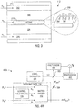
- Fig. 1 illustrates a photon detector 100 in accordance with an embodiment of the invention.
- Photon detector 100 includes a photonic gate 110 and a measurement system 120.
- P IN > are input to photonic gate 110, where the photon states interact before exiting as evolved states
- Photonic gate 110 is preferably such that the interaction of photon states
- P OUT > may alternatively differ in intensity or some other measurable property from input probe state
- photonic gate 110 causes scattering of a portion of probe state
- Measurement system 120 can use homodyne or heterodyne measurement techniques to measure output probe photon state
- S IN > could have been originally in a Fock state, in which case the input and output signal state have the same photon number, or input signal state
- photonic gate 110 uses a matter system 112 and a control field source 114 suitable for providing electromagnetically induced transparency (EIT).
- EIT is a well-known phenomenon in which an atom, molecule, or other condensed matter system that would normally absorb photons of a particular frequency is made transparent to the photons of that frequency through application of one or more electromagnetic fields having other frequencies.
- EIT generally requires a matter system having at least three quantum energy levels that are available for interactions with photons.
- matter system 112 includes at least one atom, molecule, or other quantum system having four or more energy levels, and the angular frequencies ⁇ a , ⁇ b , and ⁇ c respectively of signal state
- Fig. 2A illustrates the energy levels of energy states
- photons of angular frequency ⁇ a couple atomic energy state
- Photons of angular frequency ⁇ b and ⁇ c couple the metastable energy state
- Fig. 2A shows the fourth energy state
- 3> is metastable in that no single-photon spontaneous emission is permitted during the time scale of the detection. Such metastability may result, for example, if the spin/angular momentum of energy state
- 1> available lower energy states
- 4> is suppressed by selecting a matter system for which the fourth energy state
- Detuning parameters v a , v b , and v c indicated the respective amount of detuning of angular frequencies ⁇ a , ⁇ b , and ⁇ c from resonances of the energy level transitions of the matter system as indicated in Equations 1.
- 4> are ⁇ 12 , ⁇ 32 , and ⁇ 34 , respectively, where is the reduced Plank constant.
- Fig. 2B shows a manifold corresponding to product states
- X indicates the energy level 1 to 4 of the matter system
- A, B, and C indicate the numbers of photons of angular frequencies ⁇ a , ⁇ b , and ⁇ c , respectively.
- the illustrated manifold includes the states closest in energy to a matter system in energy state
- the product states of the system include a series of manifolds that are similar to Fig. 2B but with different numbers of free photons.
- 2B illustrates that when the detuning parameters are small, a system in state
- Equation 2A The four-level matter system of Fig. 2A when pumped with photons of angular frequency ⁇ b mediates an interaction between photons of angular frequencies ⁇ a and ⁇ c .
- the resulting interaction has a Hamiltonian H with an optical non-linearity that under conditions set forth in the above-cited paper of Beausoleil et al. has the form given by Equation 2A.
- creation operator â ⁇ and annihilation operator â respectively create and destroy a photon of angular frequency ⁇ a
- creation operator ⁇ ⁇ and annihilation operator ⁇ respectively create and destroy a photon of angular frequency ⁇ c .
- Constant ⁇ indicates the strength of the interaction and generally depends on detuning parameters v a , v b , and v c , the Rabi frequencies ⁇ a , ⁇ b , and ⁇ c associated with transitions, and the specific characteristics of the matter system.
- H ⁇ a ⁇ ⁇ a ⁇ c ⁇ ⁇ c ⁇
- Equation 2B illustrates a more general representation of a term of a Hamiltonian providing a non-linear interaction between photons of angular frequencies ⁇ a and ⁇ c .
- f (â ⁇ ,â) is a function of creation and annihilation operators â ⁇ and â
- g ( ⁇ ⁇ , ⁇ ) is a function of creation and annihilation operators ⁇ ⁇ and ⁇ .
- f (â ⁇ ,â) is a power of photon number operator â ⁇ ,â, e.g., (â ⁇ â) ⁇ for some constant ⁇ , so that the effect of the interaction on the state of photons of angular frequency ⁇ c directly depends on the number of photons of angular frequency ⁇ a .
- H ⁇ ⁇ f a ⁇ ⁇ , a ⁇ ⁇ g c ⁇ ⁇ , c ⁇
- Optical systems or gates that provide a general non-linear interaction between photon states in two distinct modes may be built from a sequence of optical gates, with or without using an EIT system.
- EIT electronic information technology
- Seth Lloyd and Samuel L. Braunstein, "Quantum Computations over Continuous Variables," Phys. Rev. Lett. 82, 1784 (1999 ) describes constructing a sequence of gates that creates an arbitrary polynomial Hamiltonian (e.g., f (â ⁇ ,â) or g ( ⁇ ⁇ , ⁇ )) for a single photon mode.
- the basic gates in the sequence for a single mode include (1) linear devices such as beam splitters and phase shifters, (2) quadratic devices such as squeezers, and (3) non-linear devices of third or higher order such as Kerr-effect fibers, atoms in optical cavities, and non-linearities generated through measurement.
- linear devices such as beam splitters and phase shifters
- quadratic devices such as squeezers
- non-linear devices of third or higher order such as Kerr-effect fibers, atoms in optical cavities, and non-linearities generated through measurement.
- Such systems for two separate modes can be combined via one or more beam splitters to provide cross mode interactions and create a desired non-linear interaction f (â ⁇ ,â) g ( ⁇ ⁇ , ⁇ ) between the modes.
- matter system 112 includes one or more four-level atoms or molecules having quantum energy levels related to the photon energies as illustrated in Fig. 2A and therefore provides a crossed-Kerr non-linearity of the form given in Equation 2A.
- Fig. 3 illustrates an embodiment of matter system 112.
- matter system 112 includes a substrate 310 containing waveguides 312, 314, and 316.
- Waveguides 312, 314, and 316 respectively receive light beams having angular frequencies ⁇ a , ⁇ b , and ⁇ c .
- Confinement structures 354 attach a series of four-level atoms 352 to the central waveguide 314.
- Each confinement structure 354 can be a molecular tether or other similar structure that reduces thermal vibrations of a four-level atom 352, and in one specific embodiment, confinement structures 354 are carbon fullerenes that act to cage four-level atoms 352.
- Each atom 352 can be any atom that provides four accessible energy levels having the above-described relations, and atoms 352 may be, for example, atoms of a lanthanide series metal such as erbium (Er) or praseodymium (Pr), an alkali metal such as rubidium (Rb) or cesium (Cs), or an alkaline earth metal. In a typical system, a few hundred atoms 352 may be needed to achieve a desired phase shift in the probe state.
- the spacing of atoms 352 relative to waveguides 312, 314, and 316 is such that atoms 352 interact with the evanescent fields surrounding waveguides 312, 314, and 316.
- the interaction causes EIT with a phase shift resulting in the probe photons of angular frequency ⁇ c .
- Material 320 around atoms 352 can form a photonic bandgap crystal that prevents propagation of photons corresponding to spontaneous emissions from the fourth energy level of atoms 352.
- a defect or other structure between atoms 352 and waveguides 312 and 316 may be provided to increase the interaction of atoms 352 with photons from waveguide 316, which have angular frequency ⁇ c .
- detector 100 of Fig. 1 can distinguish state
- a laser or other control field source 114 drives control field 116 at angular frequency ⁇ b , which corresponds to the transition between the second and third energy levels of the four-level atom.
- P IN > can be a Fock state, a coherent state, or a squeezed state containing easily measured number (e.g., 10 to 10 5 or more) of photons of angular frequency ⁇ c , which corresponds to the transition between the third and fourth energy levels of the four-level atom.
- the roles of angular frequencies ⁇ a and ⁇ c can be interchanged because of the symmetry of the Hamiltonian term of Equation 2A.
- P IN > is a coherent state
- ⁇ > c is used as an example since coherent states are easily produced (or approximated) by the output from a laser.
- other types of photonic states such as squeezed states or Fock states could equally be employed as probe state
- Equations 3 mathematically represent coherent state
- ⁇ represents the state amplitude
- the subscript c designates that the state contains photons of angular frequency ⁇ c
- n> c is a Fock state containing n photons of angular frequency ⁇ c
- nv is the expectation value of the number of photon in the coherent state
- ⁇ ⁇ c e ⁇ 1 2
- 2 ⁇ n 0 ⁇ ⁇ n t n !
- n ⁇ c ⁇ t ⁇ n V ⁇ e ⁇ i ⁇ c t
- S IN > then no phase shift occurs (e in ⁇ t 1). However, if one (or more) photon of angular frequency ⁇ a is present in signal state
- the size of the phase shift e in ⁇ t depends directly on the number n of photons in signal state
- the interaction time t can be effectively increased by increasing the number of four-level atoms or molecules that interact with states
- the homodyne measurement in system 400A uses an oscillator or laser 410 to generate a reference beam LO that is out of phase with probe state
- An adjustable delay element can be placed in the path of the reference beam LO to allow adjustment of phase angle ⁇ .
- a 50/50 beam splitter 423 at the intersection of the two beams causes subtraction of reference beam LO from probe state
- a difference Id in the resulting currents of photodiodes 427 and 428 is proportional to position quadrature ⁇ X> when phase angle ⁇ is zero and is proportional to momentum quadrature ⁇ Y> when phase angle ⁇ is ⁇ /2.
- Equation 4 the measured quadratures ⁇ X> and ⁇ Y> are related to the number n of photons in signal state
- ⁇ X > 2 ⁇ cos n ⁇ t
- Y > 2 ⁇ sin n ⁇ t
- the interaction time t can be controlled, for example, through the number of four-level atoms or molecules in matter system 112 and/or through adjustment of detuning parameters v a , v b , and v c .
- measured quadratures ⁇ X> and ⁇ Y> provide definite and easily distinguished signatures indicating the presence or absence of a photon.
- the interaction time t is not required to be such that sin(n ⁇ t) is unity. If the product ⁇ t is small enough that the small angle approximation applies to Equation 6, the momentum quadrature ⁇ Y> is approximately 2 ⁇ t for a single photon of angular momentum ⁇ a in signal state
- Fig. 4B illustrates a measurement system 400B that uses a Mach-Zehnder interferometer including 50/50 beam splitters 421 and 423, reflectors 422 and 424, and photodiodes 427 and 428 to measure the phase shift in a coherent probe photon state
- 50/50 beam-splitter 421 splits the coherent state
- ⁇ / ⁇ 2> X is input into photonic gate 110, where that mode
- ⁇ e in ⁇ t / 2> X from photonic gate 110 reflects from mirror 424 onto 50/50 beam splitter 423, which combines phase-shifted state
- the output probe state after beam-splitter 423 is a two-mode state as indicated in Equation 7, where subscripts X and Y designate spatially separated paths to respective detectors 427 and 428.
- P OUT > Y
- the output probe state can be expressed as
- Photodiode 428 can be a conventional device that is unable to distinguish a single photon from zero or two photons, but photodiode 428 can distinguish between zero and a large number of photons. Assuming that the product ⁇ t is relatively large, photodiode 428 can efficiently distinguish whether output mode
- System 400B thus has enormous advantages over currently used detectors because the efficiency of system 400B detecting single photons is close to unity.
- Equation 8 indicates that signal state
- 2> a include photons of angular frequency ⁇ a and therefore cause phase shifts.
- the magnitude of the resulting current in photodiode 428 easily distinguishes the phase shift resulting from component state
- the current measured in photodiode 428 is approximately proportional to (n ⁇ t) 2 .
- 2> a is thus about four times the current measured for component state
- a laser can provide a continuous coherent state for probe state
- a conventional signal processor 429 can analyze the current signals from one or both of photodiodes 427 and 428 to monitor the number of photons in signal state
- measurement system 400B can be tuned to act as a parity detector for signal state
- photodiode 428 measures a probe state
- An advantage of measurement system 400B is that photodiode 428 measures light through a "dark port" that (if noise is neglected) has zero intensity unless a photon is in the signal state. The presence of a photon in the signal state thus provides a distinctive signal.
- an EIT system such as used in the exemplary embodiment of photonic gate 110 is always likely to have a limited amount of noise arising from decoherence and dephasing. Dephasing can cause a small phase shift in the probe state that would cause some light flow through the dark port of the Mach-Zehnder interferometer even when no signal photon (e.g., of angular frequency ⁇ a ) is present.
- photodiode 428 can measure the amount of light (not just the presence of light) at the dark port, and proper tuning of the phase shift induced in photonic gate 110 can make the noise insignificant compared to the amount of light from the dark port when a single signal photon is present. Photodiode 428 then distinguishes a few photons from many photons, which can be achieved using conventional photodiodes. If photonic gate 110 employs a photon loss mechanism to attenuate the probe photon state, the attenuation can similarly be maximized to distinguish the dark port signal from the noise.
- detector 400B The effects of noise and dissipation in detector 400B can be analyzed for the case where matter system 110 is an EIT system of Fig. 2A . If a probe state of angular frequency ⁇ c is used to detect photons of angular frequency ⁇ a , one of the chief sources of error in the phase shift in the probe state is dephasing on a spontaneous 3-4 transition of matter system 110. The effect of this spontaneous emission on a coherent probe state
- phase shift ⁇ depends on the exact dephasing mechanism of matter system 110. For illustrative purposes, a square profile ranging from - ⁇ 0 to ⁇ 0 is assumed here, but a similar answer is obtained for a Gaussian or Poisson distribution. Integrating Ic over this phase distribution the current I c is of the form of Equation 10 in the limit where ⁇ 0 small. Thus the single photon can be distinguished from no photon as long as (1 cos [ ⁇ t]) is much greater than ⁇ 0 2 . Basically this requires selection of the phase shift ⁇ t to be larger than the possible random phase ⁇ 0 . I c ⁇
- Fig. 4C illustrates a detector 400C in accordance with yet another embodiment of the invention.
- a laser or other beam source produces a probe beam in a coherent state.
- a weak beam splitter 426 splits off a small fraction (e.g., 5 to 10%) of the coherent state to form input probe state
- P IN > is preferably a coherent state
- Control field source 114 is preferably a laser producing light having an output angular frequency ⁇ b . Accordingly, the control field is more accurately described as a coherent photon state
- ⁇ b > can differ from that of a classical electromagnetic field, particularly when state
- ⁇ c > can be derived from the evolution of Fock states.
- Fock states components containing n a , n b , and n c photons respectively drive the three frequency channels of the resonant four-level manifold of the quantum system.
- matter system 110 includes N four-level atoms that are fixed and stationary in a volume that is small compared to the optical wavelengths, and if the durations of the three pulse envelope functions of the Fock states are long compared to the lifetime of atomic level 2, the unperturbed number eigenstate
- Equation 11 generally depends on the properties of the matter system and the angular frequencies ⁇ a , ⁇ b , and ⁇ c .
- Equations 12A and 12B give the quantity W in the case where angular frequencies ⁇ a and ⁇ b are precisely tuned to the respective atomic transition angular frequencies ⁇ 12 and ⁇ 32 , dephasing is negligible, and the spontaneous emission branching ratios from atomic levels 2 and 4 are approximately unity.
- N is the number of four-level atoms
- ⁇ a , ⁇ b , and ⁇ c are the effective vacuum Rabi frequencies as given in Equation 12B
- v c is the detuning parameter ( ⁇ c - ⁇ 43 )
- ⁇ 2 and ⁇ 4 are approximately equal to the spontaneous emission rates A 21 and A 43 .
- Equation 12B k is an index having values a, b, and c; ⁇ k by definition is the resonant atomic absorption cross-section 3 ⁇ k 2 /2 ⁇ at wavelength ⁇ k 2 ⁇ c/ ⁇ c ; ⁇ w 2 is the effective laser mode cross-sectional area, A k is the spontaneous emission rate between two corresponding atomic levels; and ⁇ k is the bandwidth of the profile function describing the adiabatic interaction of a pulsed laser field with a stationary atom.
- Equation 12A indicates that W for four-level EIT system is complex, indicating potential absorption of the photons of frequency ⁇ a .
- Equation 13 simplifies to the requirement that v c / ⁇ 4 be large when
- 2 / ⁇ 2 is about equal to [ ⁇ c
- 1, n a , n b , n c > acquires purely a phase-shift from the nonlinear mechanism.
- This phase shift can be the basis of a high-efficiency nondestructive detector.
- Equation 14 shows the evolution after a time t of an N-atom quantum state during an interaction with an n a -photon Fock state in the a channel, and weak coherent states parameterized by ⁇ b and ⁇ c in the b and c channels, respectively.
- Equation 15 defines the phase shift ⁇ .
- Equations 14 and 15 show that evolved state
- Equation 16 defines the quadrature homodyne operator x ⁇ ( ⁇ ) in terms of creation operator ⁇ ⁇ and annihilation operator ⁇ for photons of angular momentum ⁇ c .
- the quadrature homodyne operator x ⁇ ( ⁇ ) is equal to the position operator X for ⁇ equal to zero and equal to momentum operator Y for ⁇ equal to ⁇ /2.
- Equation 18 The expectation value of the quadrature homodyne operator x ⁇ ( ⁇ ) can be evaluated for the evolved state of Equation 14 yielding Equations 17. Similarly, the mean square of the quadrature homodyne operator x ⁇ ( ⁇ ) can be evaluated yielding Equation 18.
- Equation 19 gives the signal-to-noise ratio for a photon detector measurement based on the momentum quadrature in detector 400C.
- functional dependence (1) and (0) indicate the number n a of photons of angular frequency ⁇ a in the state for which the expectation value is evaluated. Since the photon states are nearly coherent, the probability of a false positive count for a state where the number n a of angular frequency ⁇ a is equal to 1 is given in Equation 20.
- SNR ⁇ Y 1 ⁇ ⁇ ⁇ Y 0 ⁇ ⁇ Y 2 1 ⁇ ⁇ ⁇ Y 1 ⁇ 2
- P error e ⁇ 2 ⁇ c sin ⁇ / 2 2
- Plots 510, 520, and 530 of Fig. 5A respectively correspond to parameter ⁇ c equal to 4, 5, and 6 when the control field 116 and the probe state have the same strength (e.g.,
- ⁇ c ).
- each curve in Fig. 5A would be given by 2
- the peaks of plots 510, 520, and 530 correspond to phase shifts smaller than ⁇ /2 because of the dependence of the summand in Equation 14 on number n b .
- 2 should be greater than about 8 ⁇ or about 25 to create a sufficiently large transparency window in the a channel for the parameters chosen here.
- the number of atoms needed to provide a sufficiently low probability of a false positive detection can be determined from Fig. 5A and Equation (14).
- SNR 2.66 (or false detection probability of 0.08%) with an absorption rate of 0.08 percent.
- Fig. 5A also indicates that for a given value of v c / ⁇ 4 and ⁇ c the effect of increasing the number N of atoms eventually leads to a decrease in the signal-to-noise ratio. This results from creating a phase shift that is too large. If a larger number N of atoms are going to be used, one way to avoid the decrease in signal-to-noise ratio is to decrease the ratio v c / ⁇ 4 .
- Fig. 5B shows the signal-to-noise ratio given by Equation 19 as a function of ratio v c / ⁇ 4 for 1000 atoms localized in the interaction region. Plots 540, 550, and 560 of Fig. 5B respectively correspond to parameter ⁇ c equal to 4, 5, and 6 when the control field 116 and the probe state have the same strength (e.g.,
- ⁇ c ).
- S IN > corresponds to a wave packet containing zero or one photon of angular frequency ⁇ a and having a pulse width long enough to fit through the transparency window of EIT system.
- control field source generates a continuous beam having a coherent state and a power or energy about 10 to 100 times that of the signal state
- Control field source 114 may include a laser with an attenuator or a beam splitter in the beam path so that the resulting control field 116 has the desired energy.
- P IN > corresponds to a continuous beam similarly having an energy or power during the signal pulse width that is about the same as that of the control field.
- P IN > from the beam corresponding to the local oscillator LO may direct less than 10% of the beam power from a laser into probe state
- Fig. 4D shows a measurement system 400D in accordance with an embodiment of the invention using a dual homodyne (or heterodyne) measurement.
- measurement system 400D includes a beam splitter 434 that directs a portion of the output probe state
- 0> i.e., no input
- homodyne detector 420 provides a measurement of the expectation value ⁇ x ⁇ ( ⁇ ) ⁇ of the homodyne operator x ⁇ ( ⁇ ) for angle ⁇
- homodyne detector 430 provides a measurement of the expectation value ⁇ x ⁇ ( ⁇ ) + ⁇ /2) ⁇ of the homodyne operator x ⁇ ( ⁇ + ⁇ / 2) for angle ⁇ + ⁇ /2. Accordingly, measurement system 400D can obtain simultaneous information about the momentum and position quadratures for the output probe state
- Measurement systems 400A, 400B, 400C, and 400D as described above, are able to infer the presence or absence of a photon in a signal state by measuring a probe state without directly measuring and destroying the signal photon.
- SOUT> thus has a definite photon number for photons of angular frequency ⁇ a and can be used in a quantum information processing system after the measurement.
- the detectors described above provide an output state
- S OUT > will be the same as those of input state
- S IN > can correspond to absorption of the photon of signal state
- interactions such as found in EIT systems can be asymmetric (e.g., have a preferred axis), and such asymmetry can cause input states with different characteristics to evolve differently, resulting in a change in characteristics such as the polarization or the angular momentum of a photon being measured.
- Fig. 6A illustrates a detector 600 capable of measuring an input signal
- detector 600 can be constructed to preserve a different photon characteristic such as the polarization, the orbital angular momentum, the time bin, or momentum.
- detector 600 includes a beam splitting system 610, a non-destructive measurement system 620, and a beam combining system 630. The specific implementation of beam splitting system 610, measurement system 620, and beam combining system 630 will depend on the preserved characteristic.
- Beam splitting system 610 splits the input signal state
- beam splitting system 610 is a polarizing beam splitter that splits input signal state
- beam splitting system 610 may include a holographic film that separates photon states having different orbital angular momentum.
- beam splitting system 610 may spatially separate photons received during different time bins for separate measurements. Similarly, photons in a localized wave packet can be separated according to momentum for separate measurement.
- Measurement system 620 includes a set of non-destructive photon detectors 621 and 622 and a quantum coherent signal adder 624.
- Fig. 6A shows an exemplary embodiment of the invention where measurement system 620 includes two non-destructive detectors 621 and 622, which are suitable for preservation of a characteristic such as polarization that has two independent basis states. More generally, the number of non-destructive detectors in system 620 depends on the number of independent basis states used for the characteristic being preserved. For preservation of orbital angular momentum, time bin, or momentum, the number of non-destructive detectors depends on the number of available states of the preserved characteristic that may be used in the input state. The following description concentrates on the specific example of polarization preservation, but generalization to systems that preserve other characteristics such as the spin state, orbital angular momentum, time bin, or momentum of a photon state will be apparent to those of skill in the art.
- each detector 621 or 622 is capable of measuring an input mode
- the output signal from each detector 621 or 622 may be as described above with reference to Figs. 4A to 4D , for example, a difference signal Id resulting from a homodyne phase measurement or an output signal of a photodiode measuring intensity of probe photons output from a dark port in a heterodyne measurement system.
- Detector 621 is set up for measurement of mode
- detector 622 is set up for measurement of the second mode
- Quantum coherent adder 624 combines the electronic signals from detectors 621 and 622 to generate an output signal NUM indicating the total number of photons in the two modes
- portions of detectors 621 and 622 and adder 624 can be kept sufficiently cold (e.g., at or below a few mK°) so that photodiodes in detectors 621 and 622 produce quantum coherent electron states, and the electron states remain coherent through current addition process.
- the addition process may, for example, be implemented using a wired OR or a pair of diodes with output terminals connected to a wired OR.
- Output signal NUM can thus indicate when there is a photon in one of the two modes
- Signal NUM therefore provides a measurement of the photon number without changing the polarization state.
- detectors 621 and 622 can be controlled using knowledge of the characteristics (e.g., the polarizations) of photons in modes
- preferred axes of detectors 621 and 622 can be oriented (e.g., aligned with the respective polarization directions of modes
- corrective optical elements in detectors 621 and 622 can manipulate the polarizations or the phases of the separated photon states so that output modes
- Beam combining system 630 which can be a polarizing beam splitter 632 in a polarization preserving detector, constructs an output state
- system 630 can include one or more corrective optical elements 634 to make output modes
- S OUT > has the same polarization state as state
- S OUT > having a desired polarization can thus be constructed from an input state
- the total photon number for three or more modes can be measured without collapsing to a definite state corresponding to one of the modes, and the three or more modes can be recombined to produce a state with a definite photon number and the original characteristic state.
- S IN > e.g., the polarization or angular momentum state
- quantum information e.g., a qubit or a qudit
- the number of photons in the input state can be measured without destroying the quantum information that the preserved characteristic may represent.
- a photon state that represents the desired quantum information and has a measured number of photons can be constructed.
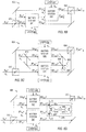
- Fig. 6B illustrates a polarization-preserving detector 602 in accordance with another embodiment of the invention.
- Detector 602 includes a beam splitter 610, a pair of EIT matter systems 641 and 642, and a beam combiner 632.
- Beam splitter 610 is a polarizing beam splitter that splits the input signal state
- Matter systems 641 and 642 are also arranged to be serially in the path of a photonic probe state
- each matter system 641 or 642 contains one or more 4-level atoms or molecules having energy levels as illustrated in Fig. 2A .
- S IN > is a state of photons having angular frequency ⁇ a
- P IN > is a state of photons having frequency ⁇ c .
- Lasers 643 and 644 illuminate respective matter systems 641 and 642 with photons of frequency ⁇ b .
- matter system 641 changes the phase of probe state
- matter system 642 changes the phase of probe state
- Beam combiner 632 combines modes
- P OUT > which depends on phase changes in both matter systems 641 and 642, can be measured using homodyne or heterodyne techniques such as described above. The resulting measurement indicates the number of photons in output signal state
- S2 IN > and/or corrective optical elements (not shown) in matter systems 641 and 642 can be used to ensure that the relative phase and polarization of modes
- S OUT > has the same polarization as input signal state
- Fig. 6C illustrates a polarization-preserving detector 604 in accordance with yet another embodiment of the invention.
- Detector 604 includes beam splitters 610 and 615, a pair of EIT matter systems 651 and 652, and a beam combiner 632.
- beam splitter 610 is a polarizing beam splitter that splits the input signal state
- Beam splitter 615 is preferably a non-polarizing 50-50 beam splitter that splits a state
- P IN > (and separate probe states
- P IN > have a definite phase relation (e.g., have the same phase).
- P2 OUT > from matter systems 651 and 652 have phases that change according to the number of photons in respective modes
- P2 OUT > can be compared to determine the total number of photons in output signal modes
- matter systems 651 and 652 are such that the change in the phase of
- detector 604 includes a non-polarizing, 50-50 beam splitter 660 that combines probe beams from matter systems 651 and 652 to create a sum and a difference of probe states
- the photodiode 662 measuring the light intensity from a dark port can indicate the presence of a photon in output signal state
- Fig. 6D illustrates a polarization-preserving photon detector 606 in accordance with an embodiment of the invention using a homodyne phase measurement of probe states
- Detector 606 includes a beam splitter 610, a pair of EIT matter systems 641 and 642, a beam combiner 632, and a homodyne measurement system 670. As described above, beam splitter 610 splits the input signal state
- lasers 643 and 644 direct control fields having frequency ⁇ a
- one or more laser or other light source directs probe states
- Matter systems 641 and 642 are preferably such that the presence of a single photon in mode
- Homodyne measurement system 670 includes beam splitters 671 and 672 that respectively split probe states
- Photodiode 674 measures the intensity of the combined portions of the probe states
- Photodiode 676 measures the intensity of the combined portions of the probe states
- Photodiodes 674 and 676 and the alignment of the components from beam splitters 671 and 672 are preferably such that output currents from photodiodes 674 and 676 provide no indication of whether the photons detected are from probe state
- a signal from a differential amplifier 678 connected to photodiodes 674 and 676 can be used to determine whether at least one of the probe states
- a beam combining system including beam combiner 632 can construct an output state
- a non-destructive photon detector in accordance with an embodiment of the invention can convert a conventional, non-deterministic photon source that may sporadically or undependably emit a single photon into a deterministic photon source that releases a single photon on demand.
- the deterministic single photon source includes the conventional photon source, the non-destructive photon detector, and a photon storage system.
- the photon detector includes an EIT system
- the BIT system can introduce a phase shift in a probe state for signal measurement and store the signal photon for later release.
- the non-destructive photon detector measures the photon number for a state output from the conventional photon source.
- the measured output state is not a single photon
- another output photon state from the conventional photon source is measured. If the measured photon state contains a single photon, the measured photon state is stored in the photon storage system, from which the single photon state can be released on demand. If the non-destructive detector preserves a characteristic such as the polarization or angular momentum of the photon from the conventional photon source, the stored photon state will have the same characteristic as the input photons.
- Fig. 7A illustrates a deterministic single photon source 700 in accordance with a specific embodiment of the invention.
- Photon source 700 includes a photonic gate 110, a measurement system 720, a non-deterministic photon source 730, and a photon storage system 740.
- Non-deterministic photon source 730 sometimes emits a single photon of angular frequency ⁇ a , but most of the time emits only the vacuum.
- a source can be, for example, an electrically triggered quantum dot or highly attenuated laser.
- the output of photon source 730 is measured to determine whether or not source 730 emitted a photon.
- the output state of source 730 becomes the signal state
- a laser or other probe source 710 simultaneously generates a probe state such as a coherent state
- Photodiodes 427 and 428 and signal processor 429 then determine whether signal state
- Photon storage 740 can be a device such as a fiber loop or an EIT system capable of releasing a quantum coherent photon state matching the stored photon. The stored photon can be released from photon storage 740 to deterministically provide a single photon state on demand.
- an EIT-based arrangement used in photonic gate 110 which causes the desired phase shift in the probe state, can also store a single photon of the signal state.
- the duration of the probe state can be extended to effectively slow or stop propagation of the signal photon through matter system 112 until an output photon is needed. Accordingly, a separate photon storage device 740 can be eliminated if matter system 112 serves to store the signal photon.
- An array of N dependable single photon sources of this type can store N photons and release a user-selected number of (e.g., 0 to N) photons on demand.
- Fig. 7B shows an N-photon source 750 including multiple deterministic photon sources 700-1 to 700-N that can be used together to produce a photon state containing a user-selected number of photons.
- Each of the single photon sources 700-1 to 700-N operates in the same manner as photon source 700 of Fig. 7A to detect and store a single photon.
- photon sources 700-1 to 700-N all store single photons, any or all of the photon sources 700-1 to 700-N can be commanded to release a stored photon to produce a photon state having a user selected number of photons.
Landscapes
- Engineering & Computer Science (AREA)
- Physics & Mathematics (AREA)
- Theoretical Computer Science (AREA)
- General Physics & Mathematics (AREA)
- Nanotechnology (AREA)
- Chemical & Material Sciences (AREA)
- Mathematical Physics (AREA)
- Data Mining & Analysis (AREA)
- Software Systems (AREA)
- Mathematical Optimization (AREA)
- Pure & Applied Mathematics (AREA)
- Computing Systems (AREA)
- General Engineering & Computer Science (AREA)
- Evolutionary Computation (AREA)
- Mathematical Analysis (AREA)
- Condensed Matter Physics & Semiconductors (AREA)
- Computational Mathematics (AREA)
- Crystallography & Structural Chemistry (AREA)
- Artificial Intelligence (AREA)
- Spectroscopy & Molecular Physics (AREA)
- Optical Modulation, Optical Deflection, Nonlinear Optics, Optical Demodulation, Optical Logic Elements (AREA)
- Investigating Or Analysing Materials By Optical Means (AREA)
- Photometry And Measurement Of Optical Pulse Characteristics (AREA)
Description
- Interest in quantum information processing has grown dramatically because of recent successes in developing quantum systems and the expected capabilities of the technology. In particular, working quantum cryptosystems have been developed, and if large (many qubit) quantum computers can be built, quantum computers will perform many processing tasks much more efficiently than can classical computers. Quantum processors having tens or hundreds of qubits, for example, would be able to perform quantum simulations unreachable with any classical machine. Such quantum processors also have the potential to extend the working distances and applicability of quantum communications:
- Many candidate technologies for quantum computing hardware are currently being studied. Whichever technology turns out to be the most practical, quantum coherent communications will likely be needed for linking separate quantum computers. Coherent electromagnetic fields (as photonic qubits) seem ideal for communications between quantum computers and for general quantum communications because light, traveling either down optical fibers or through free space, can carry quantum information over large distances. Further, some quantum computing may be performed directly on photonic qubits, using non-linear or linear quantum optical processes.
- Proposed quantum information systems that use photon states often require detectors capable of efficiently detecting the presence or absence of one or a few photons. One proposed optical quantum computation architecture by E. Knill, R. Laflamme, and G. Milburn, Nature 409, 46 (2001), for example, requires a high-efficiency photon detector that is more than 99.99% efficient at distinguishing quantum states including 0, 1, or 2 photons. A miscount of the number of photons or a failure to detect the presence of a photon causes an inaccurate measurement of the photon state and an error in evaluation of the quantum information. Such errors, when tolerable, require error correction schemes that may be expensive to implement.
- Current commercial single photon detectors generally rely to a greater or lesser extent on the photoelectric effect. With the photoelectric effect, photons incident on the surface of a metal, a semiconductor, or another material liberate electrons from atoms of the material. The excited electrons enter the surrounding space or a conduction band, where the electrons are collected as current that can be amplified and measured.
- The photoelectric current from a single photon is small and difficult to detect. The best commercial photon detectors for visible light currently have a quantum efficiency of about 90% for detecting single photons, and the efficiency achieved in practice is much lower. At present, detectors for single photons having wavelengths between 1.3 and 1.5 µm are only about 30% efficient. These efficiencies are too low for many quantum information systems. Additionally, the best efficiencies achieved for the visible-spectrum photon detectors require cooling the detectors down to about 6 °K, and such detectors still provide relatively high "dark count" rates (e.g., high background noise when no photon is incident.)
- Another drawback of most current photon detectors is that the detectors absorb the photons being measured or detected. The photon detectors can thus only be used at the end of a process, when the measured photons are no longer required or when the resulting measurement controls a condition of the system.
- Accordingly, quantum information systems require photon detectors that are highly efficient at detecting photons and that can accurately distinguish the number of photons in a quantum signal. Ideally, the detectors would be non-destructive, so that after the presence or number of photons has been inferred, the photon states could be used thus providing more efficient use of resources.
- KARLSSON A ET AL: "Quantum correlations in dual quantum measurements" APPLIED PHYSICS B (LASERS AND OPTICS) SPRINGER-VERLAG GERMANY, vol. 64, no. 2, February 1997 (1997-02), pages 235-241, XP008065251 ISSN: 0946-2171 describes analyzes the quantum measurement properties of dual non-degenerate parametric amplifiers in a twin-beam configuration, in the cascaded back-action-evasion configuration, and in Kerr-type photon-number quantum non-demolition measurements. It is found that Einstein-Podolsky-Rosen correlations can be obtained between the quadrature components of an idler mode and the sum of the readout of two signal modes. Furthermore, dual-mode quantum non-demolition measurements on the combination of two light modes, and the generation of number-state entanglement are described.
- It is an object of the invention to provide an approach allowing the detection of the photon number of an input state without changing a characteristic, e.g., the polarization or angular momentum of the input state.
- This object is achieved by a device of
claim 1, and by a method ofclaim 6. -
-
Fig. 1 is a block diagram of a number-resolving photon detector in accordance with an embodiment of the invention. -
Figs. 2A and 2B respectively illustrate semi-classical energy levels and a quantum energy manifold for a matter system suitable for use in the photon detector ofFig. 1 . -
Fig. 3 illustrates an exemplary embodiment of a matter system suitable for the photon detector ofFig. 1 . -
Figs. 4A ,4B, 4C, and 4D are block diagrams of number-resolving photon detectors in accordance with embodiments of the invention using alternative homodyne or heterodyne measurement techniques to measure changes in probe photon states. -
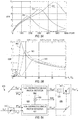
Figs. 5A and 5B show plots of the signal-to-noise ratio for a detector using low-intensity coherent states for the applied probe state and control state. -
Figs. 6A ,6B, 6C, and 6D illustrate non-destructive photon detectors in accordance with alternative embodiments of the invention that preserve a characteristic such as the polarization of an input photon signal state. -
Fig. 7A is a block diagram of a single photon source in accordance with an embodiment of the invention. -
Fig. 7B is a block diagram of an N-photon source in accordance with an embodiment of the invention. - Use of the same reference symbols in different figures indicates similar or identical items.
- In accordance with an aspect of the invention, a non-destructive photon detector uses the interactions of a probe state and a signal state with a matter system to create changes in the probe state that depend on the number of photons in the signal photon state: The matter system generally includes one or more atoms, molecules, or other quantum systems having energy level transitions respectively corresponding to the energies of photons in the probe state, the signal states, and a control field. The interactions of the photons and the matter system causes electromagnetically induced transparency (EIT) that introduces phase shifts in Fock components of the probe state without destroying the signal photons. In one embodiment, the probe state is initially in a low intensity coherent state, and the matter system transforms the probe state from a coherent state to a state that is no longer a coherent state. A homodyne or heterodyne measurement system can measure the changes in the probe state for determination of the number of photons in the signal state (e.g., whether the signal state contains 0 or 1 photon).
-
Fig. 1 illustrates aphoton detector 100 in accordance with an embodiment of the invention.Photon detector 100 includes aphotonic gate 110 and ameasurement system 120. For a measurement, a photonic signal state |SIN> and a photonic probe state |PIN> are input tophotonic gate 110, where the photon states interact before exiting as evolved states |SOUT> and |POUT>.Photonic gate 110 is preferably such that the interaction of photon states |SIN> and |PIN> inphotonic gate 110 causes a phase shift in probe state |PIN>, and the introduced phase shift depends on the number of photons in signal state |SIN>. However, output probe state |POUT> may alternatively differ in intensity or some other measurable property from input probe state |PIN>. In one alternative embodiment,photonic gate 110 causes scattering of a portion of probe state |PIN> where the scattering depends on the number of photons in signal state |SIN>. -
Measurement system 120 can use homodyne or heterodyne measurement techniques to measure output probe photon state |POUT> and determine the change that arose inphotonic gate 110. The number of photons in signal state |SOUT> is then inferred from the measurement of probe state |POUT>. Signal state |SOUT>, which is output fromphotonic gate 120, is thus in a Fock state, i.e., in a quantum state having a determined photon number. Input signal state |SIN> could have been originally in a Fock state, in which case the input and output signal state have the same photon number, or input signal state |SIN> could have been in a state that is a superposition of Fock states, in which case the measurement collapses input signal state |SIN> to output signal state |SOUT>. - The specific embodiment of
photonic gate 110 illustrated inFig. 1 uses amatter system 112 and acontrol field source 114 suitable for providing electromagnetically induced transparency (EIT). EIT is a well-known phenomenon in which an atom, molecule, or other condensed matter system that would normally absorb photons of a particular frequency is made transparent to the photons of that frequency through application of one or more electromagnetic fields having other frequencies. EIT generally requires a matter system having at least three quantum energy levels that are available for interactions with photons. - In an exemplary embodiment,
matter system 112 includes at least one atom, molecule, or other quantum system having four or more energy levels, and the angular frequencies ωa, ωb, and ωc respectively of signal state |SIN>, acontrol field 116, and probe state |PIN> are such that the photons couple to corresponding transitions between the quantum energy levels ofmatter system 112.Fig. 2A illustrates the energy levels of energy states |1>, |2>, |3>, and |4>, of a four-level matter system relative to the energies of photons having angular frequencies ωa, ωb, and ωc. With the matter system ofFig. 2A , photons of angular frequency ωa couple atomic energy state |1> to energy state |2>. Photons of angular frequency ωb and ωc couple the metastable energy state |3> to energy states |2> and |4>, respectively. - The relative order of the energy levels illustrated in
Fig. 2A is merely an example, and more generally, a reordering of energy levels would still permit EIT. In particular, althoughFig. 2A shows the fourth energy state |4> as being higher in energy than the second energy state |2>, the second state |2> as being higher in energy than the third energy state |3>, and the third energy state |3> as being higher in energy than the first energy state |1>, EIT can be produced in matter systems that provides other orderings of these energy levels. - Third energy state |3> is metastable in that no single-photon spontaneous emission is permitted during the time scale of the detection. Such metastability may result, for example, if the spin/angular momentum of energy state |3> and available lower energy states (e.g., state |1>) is such that a conservation law forbids emission of a single photon during a transition of the matter system from energy state |3> to a lower energy state. Spontaneous transitions from the fourth energy state |4> (e.g., to the first energy state |1> or the second state |2>) is suppressed by selecting a matter system for which the fourth energy state |4> is metastable or by at least partially surrounding the four-level matter system with a photonic bandgap crystal that does not permit propagation of photons having angular frequencies corresponding to the transitions from the fourth energy state |4>.
- Detuning parameters va, vb, and vc indicated the respective amount of detuning of angular frequencies ωa, ωb, and ωc from resonances of the energy level transitions of the matter system as indicated in
Equations 1. InEquations 1, the energy differences between states |1> and |2>, between |3> and |2>, and between |3> and |4> are ω12, ω32, and ω34, respectively, where is the reduced Plank constant.
-
Fig. 2B shows a manifold corresponding to product states |X, A, B, C> of the matter system with free photons of angular frequencies ωa, ωb, and ωc. In product state |X, A, B, C>, X indicates theenergy level 1 to 4 of the matter system, and A, B, and C indicate the numbers of photons of angular frequencies ωa, ωb, and ωc, respectively. The illustrated manifold includes the states closest in energy to a matter system in energy state |1> with na photons of angular frequency ωa, nb photons of angular frequency ωb, and nc photons of angular frequency ωc. The product states of the system include a series of manifolds that are similar toFig. 2B but with different numbers of free photons. The manifold ofFig. 2B illustrates that when the detuning parameters are small, a system in state |2, na-1, nb, nc> can transition to state |1, na, nb, nc> by a spontaneous emission of a single photon, but the matter system does not permit transitions from states |3, na-1, nb+1, nc> and |4, na-1, nb+1, nc-1> to state |1, na, nb, nc> by spontaneous emission of a single photon. - A paper by R. Beausoleil, W. Munro, and T. Spiller entitled "Applications of Coherent Population Transfer to Information Processing," "http://xxx.lanl.gov/abs/quant-ph/0302109" and a co-owned
U.S. patent application No. 10/364,987 , entitled "Quantum Information Processing Using Electromagnetically Induced Transparency", further describe use of four-level matter systems having energy level states as illustrated inFigs. 2A and 2B in implementations of photonic qubit gates. The references particularly describe the structure of a two-qubit phase gate suitable for use asphotonic gate 110 inFig. 1 . - The four-level matter system of
Fig. 2A when pumped with photons of angular frequency ωb mediates an interaction between photons of angular frequencies ωa and ωc. The resulting interaction has a Hamiltonian H with an optical non-linearity that under conditions set forth in the above-cited paper of Beausoleil et al. has the form given by Equation 2A. In Equation 2A, creation operator â † and annihilation operator â respectively create and destroy a photon of angular frequency ωa, and creation operator ĉ† and annihilation operator ĉ respectively create and destroy a photon of angular frequency ωc. Constant χ indicates the strength of the interaction and generally depends on detuning parameters va, vb, and vc, the Rabi frequencies Ωa, Ωb, and Ωc associated with transitions, and the specific characteristics of the matter system.
- Condensed matter systems can more generally give rise to other non-linear photon interactions that are suitable for use in detectors. Equation 2B, for example, illustrates a more general representation of a term of a Hamiltonian providing a non-linear interaction between photons of angular frequencies ωa and ωc. In Equation 2B, f(â†,â) is a function of creation and annihilation operators ↠and â, and g(ĉ†,ĉ) is a function of creation and annihilation operators ĉ† and ĉ. Preferably, f(â†,â) is a power of photon number operator â†,â, e.g., (â†â)λ for some constant λ, so that the effect of the interaction on the state of photons of angular frequency ωc directly depends on the number of photons of angular frequency ωa.

- Optical systems or gates that provide a general non-linear interaction between photon states in two distinct modes (e.g., spatially separated modes or distinct angular frequency modes ωa and ωc) may be built from a sequence of optical gates, with or without using an EIT system. In the context of quantum computing, Seth Lloyd and Samuel L. Braunstein, "Quantum Computations over Continuous Variables," Phys. Rev. Lett. 82, 1784 (1999), describes constructing a sequence of gates that creates an arbitrary polynomial Hamiltonian (e.g., f(â†,â) or g(ĉ†,ĉ)) for a single photon mode. The basic gates in the sequence for a single mode include (1) linear devices such as beam splitters and phase shifters, (2) quadratic devices such as squeezers, and (3) non-linear devices of third or higher order such as Kerr-effect fibers, atoms in optical cavities, and non-linearities generated through measurement. Such systems for two separate modes can be combined via one or more beam splitters to provide cross mode interactions and create a desired non-linear interaction f(â†,â) g(ĉ†,ĉ) between the modes.
- In an exemplary embodiment of
detector 100 described herein,matter system 112 includes one or more four-level atoms or molecules having quantum energy levels related to the photon energies as illustrated inFig. 2A and therefore provides a crossed-Kerr non-linearity of the form given in Equation 2A.Fig. 3 illustrates an embodiment ofmatter system 112. In the illustrated embodiment,matter system 112 includes asubstrate 310 containingwaveguides Waveguides -
Confinement structures 354 attach a series of four-level atoms 352 to thecentral waveguide 314. Eachconfinement structure 354 can be a molecular tether or other similar structure that reduces thermal vibrations of a four-level atom 352, and in one specific embodiment,confinement structures 354 are carbon fullerenes that act to cage four-level atoms 352. Eachatom 352 can be any atom that provides four accessible energy levels having the above-described relations, andatoms 352 may be, for example, atoms of a lanthanide series metal such as erbium (Er) or praseodymium (Pr), an alkali metal such as rubidium (Rb) or cesium (Cs), or an alkaline earth metal. In a typical system, a few hundredatoms 352 may be needed to achieve a desired phase shift in the probe state. - The spacing of
atoms 352 relative towaveguides atoms 352 interact with the evanescentfields surrounding waveguides Material 320 aroundatoms 352 can form a photonic bandgap crystal that prevents propagation of photons corresponding to spontaneous emissions from the fourth energy level ofatoms 352. However, a defect or other structure betweenatoms 352 andwaveguides atoms 352 with photons fromwaveguide 316, which have angular frequency ωc. - The exemplary embodiment of
detector 100 ofFig. 1 can distinguish state |0>a from state |1>a if signal state |SIN> is in the Fock state |0>a or |1>a, i.e., a state including zero or one photon of angular frequency ωa. More generally, signal state |SIN> could contain up to n photons (where n is arbitrary), anddetector 100 can efficiently determine the number n of photons. For the determination of the number of photons of angular frequency ωa, in signal state |SIN>, a laser or othercontrol field source 114 drivescontrol field 116 at angular frequency ωb, which corresponds to the transition between the second and third energy levels of the four-level atom. Probe state |PIN> can be a Fock state, a coherent state, or a squeezed state containing easily measured number (e.g., 10 to 105 or more) of photons of angular frequency ωc, which corresponds to the transition between the third and fourth energy levels of the four-level atom. Alternatively, the roles of angular frequencies ωa and ωc can be interchanged because of the symmetry of the Hamiltonian term of Equation 2A. - In one exemplary embodiment described below, probe state |PIN> is a coherent state |α>c. The coherent state |α>c is used as an example since coherent states are easily produced (or approximated) by the output from a laser. However, other types of photonic states such as squeezed states or Fock states could equally be employed as probe state |PIN>.
- Equations 3 mathematically represent coherent state |α>c in terms of Fock states |n>c having definite numbers of photons of angular frequency ωc. In Equations 3, α represents the state amplitude, the subscript c designates that the state contains photons of angular frequency ωc, |n>c is a Fock state containing n photons of angular frequency ωc, and nv is the expectation value of the number of photon in the coherent state |α>c.

- When probe state |PIN> is a coherent state |α>c and the signal state |SIN> is a Fock state containing n photons, the initial state |SIN>|PIN> of
detector 100 is |n>a|α>c, where subscripts a and c respectively represent photons of angular frequencies ωa and ωc. (For this approximation,control field source 114 classically pumps four-level matter system 112 with photons of angular frequency ωb.) The effect of the crossed-Kerr non-linearity of Equation 2A now causes the photon states to evolve in time according toEquation 4.
-
Equation 4 clearly shows that if no photon of angular frequency ωa is present (n=0) in signal state |SIN> then no phase shift occurs (einχt=1). However, if one (or more) photon of angular frequency ωa is present in signal state |SIN>, coherent state |α>c evolves to |αeinχt>c. The size of the phase shift einχt depends directly on the number n of photons in signal state |SIN> as well as on coupling χ and the interaction time t of the photons with the four-level matter systems. To increase the size of the phase shift, the interaction time t can be effectively increased by increasing the number of four-level atoms or molecules that interact with states |SIN> and |PIN>, e.g., by increasing the number of interacting four-level atoms in the optical path of the photon states |SIN> and |PIN>. Since the coupling χ and interaction time t can be fixed and known for a particular system, a measurement of the phase shift indicates the number n of photons in signal state |SIN>. - If value α for the coherent state is initially real, a
measurement system 400A ofFig. 4A can use homodyne measurement techniques to measure the position X = ĉ + ĉ† and momentum Y = (ĉ-ĉ†)/i quadratures <X> and <Y> for probe state |POUT>. The homodyne measurement insystem 400A uses an oscillator orlaser 410 to generate a reference beam LO that is out of phase with probe state |POUT> by a phase angle θ. An adjustable delay element can be placed in the path of the reference beam LO to allow adjustment of phase angle θ. A 50/50beam splitter 423 at the intersection of the two beams causes subtraction of reference beam LO from probe state |POUT> along a path to aphotodiode 427 and addition of reference beam LO to probe state |POUT> along a path to aphotodiode 428. A difference Id in the resulting currents ofphotodiodes - Based on
Equation 4, the measured quadratures <X> and <Y> are related to the number n of photons in signal state |SIN> (and to the constants α, χ, and t) as respectively indicated inEquations 5 and 6.

- If no photon of angular frequency ωa is present (n=0), the measured position quadrature <X> is equal to twice value α, and measured momentum quadrature <Y> is zero. If one photon of angular frequency ωa is present (n=1), interaction time t can be controlled so that quadrature <X> is zero and quadrature <Y> is 2α. (The interaction time t can be controlled, for example, through the number of four-level atoms or molecules in
matter system 112 and/or through adjustment of detuning parameters v a, v b, and v c.) Thus, for an appropriately controlled reaction time t, measured quadratures <X> and <Y> provide definite and easily distinguished signatures indicating the presence or absence of a photon. - The interaction time t is not required to be such that sin(nχt) is unity. If the product χt is small enough that the small angle approximation applies to
Equation 6, the momentum quadrature <Y> is approximately 2αχt for a single photon of angular momentum ωa in signal state |SIN>. If parameter α is sufficiently large, the measurement of quadrature <Y>, which is about 2αχt, will be much larger than signal noise, and the one-photon signal state is efficiently distinguished from the signal state containing no photons. - The measurement process illustrated above uses a homodyne measurement, which is highly efficient but generally requires the use of a strong local oscillator.
Fig. 4B illustrates ameasurement system 400B that uses a Mach-Zehnder interferometer including 50/50beam splitters 421 and 423,reflectors photodiodes system 400B, 50/50 beam-splitter 421 splits the coherent state |α> into a two-mode separable state |α/√2>Xα/√2>Y, where subscripts X and Y designate spatially separated paths. One mode |α/√2>X is input intophotonic gate 110, where that mode |α/√2>X acquires a phase shift einχt that depends on the number n of photons of angular frequency ωa in signal state |SIN>. The phase shifted state |αeinχt/ 2>X fromphotonic gate 110 reflects frommirror 424 onto 50/50beam splitter 423, which combines phase-shifted state |αeinχt/ 2>X with the second mode |α/√2>Y from beam splitter 421 viamirror 422. The output probe state after beam-splitter 423 is a two-mode state as indicated in Equation 7, where subscripts X and Y designate spatially separated paths torespective detectors 
- In the regime where χt is small, the output probe state can be expressed as |α(1+inχt/2)>x|inαχt/2>Y and a direct measurement of second mode |inαχt/2>Y using
photodiode 428 gives a measurement current proportional to photon intensity (nαχt)2.Photodiode 428 can be a conventional device that is unable to distinguish a single photon from zero or two photons, butphotodiode 428 can distinguish between zero and a large number of photons. Assuming that the product αχt is relatively large,photodiode 428 can efficiently distinguish whether output mode |POUT>Y has 0 or approximately (αχt)2 photons.System 400B thus has enormous advantages over currently used detectors because the efficiency ofsystem 400B detecting single photons is close to unity. - If signal state |SIN> is a superposition of Fock states and of the form c0|0>a+c1/1>a, the state |Ψ'> of the total system after the beam splitter and EIT interaction is found to have the approximate form given in
Equation 8. Ifphotodiode 428 measures a nonzero current, thenEquation 8 indicates that signal state |SOUT> includes a photon of angular frequency ωa.
- If signal state |SIN> is a superposition of Fock states and of the form c0/0>a+c1/1>a+c2/2>a, both component Fock states |1>a and |2>a include photons of angular frequency ωa and therefore cause phase shifts. However, the magnitude of the resulting current in
photodiode 428 easily distinguishes the phase shift resulting from component state |1>a from the phase shift resulting from component state |2>a. As noted above, when χt is small, the current measured inphotodiode 428 is approximately proportional to (nαχt)2. The current that photodiode 428 measures for component state |2>a is thus about four times the current measured for component state |1>a. - In one operating mode of
measurement system 400B, a laser can provide a continuous coherent state for probe state |PIN>, whilecontrol field source 114 continuously pumpsmatter system 112. With the control field and probe state being continuous,measurement system 400B does not require synchronization of probe state |PIN> and signal state |SIN>. Aconventional signal processor 429 can analyze the current signals from one or both ofphotodiodes - In accordance with another aspect of the invention,
measurement system 400B can be tuned to act as a parity detector for signal state |SIN>. As noted above,photodiode 428 measures a probe state |(1-einχt)α/2>Y. Ifphotonic gate 110 is such that the quantity χt is equal to π, then even photon numbers produce a phase shift that is a multiple of 2π, which is effectively no phase shift. Only an odd photon number n of photons in signal state |SIN> causes a phase shift, which photodiode 428 detects as a non-zero current. - An advantage of
measurement system 400B is thatphotodiode 428 measures light through a "dark port" that (if noise is neglected) has zero intensity unless a photon is in the signal state. The presence of a photon in the signal state thus provides a distinctive signal. However, an EIT system such as used in the exemplary embodiment ofphotonic gate 110 is always likely to have a limited amount of noise arising from decoherence and dephasing. Dephasing can cause a small phase shift in the probe state that would cause some light flow through the dark port of the Mach-Zehnder interferometer even when no signal photon (e.g., of angular frequency ωa) is present. However,photodiode 428 can measure the amount of light (not just the presence of light) at the dark port, and proper tuning of the phase shift induced inphotonic gate 110 can make the noise insignificant compared to the amount of light from the dark port when a single signal photon is present.Photodiode 428 then distinguishes a few photons from many photons, which can be achieved using conventional photodiodes. Ifphotonic gate 110 employs a photon loss mechanism to attenuate the probe photon state, the attenuation can similarly be maximized to distinguish the dark port signal from the noise. - The effects of noise and dissipation in
detector 400B can be analyzed for the case wherematter system 110 is an EIT system ofFig. 2A . If a probe state of angular frequency ωc is used to detect photons of angular frequency ωa, one of the chief sources of error in the phase shift in the probe state is dephasing on a spontaneous 3-4 transition ofmatter system 110. The effect of this spontaneous emission on a coherent probe state

detector 427 measures depends on the random phase shift φ as indicated in Equation 9.
- The distribution for phase shift φ depends on the exact dephasing mechanism of
matter system 110. For illustrative purposes, a square profile ranging from -φ0 to φ0 is assumed here, but a similar answer is obtained for a Gaussian or Poisson distribution. Integrating Ic over this phase distribution the current Ic is of the form ofEquation 10 in the limit where φ0 small. Thus the single photon can be distinguished from no photon as long as (1 cos [χt]) is much greater than φ0 2. Basically this requires selection of the phase shift χt to be larger than the possible random phase φ0.
-
Fig. 4C illustrates adetector 400C in accordance with yet another embodiment of the invention. Fordetector 400C, a laser or other beam source produces a probe beam in a coherent state. Aweak beam splitter 426 splits off a small fraction (e.g., 5 to 10%) of the coherent state to form input probe state |PIN> and leave a strong local oscillator signal LO. Input probe state |PIN> is preferably a coherent state |αc> having a photon number expectation value |αc|2 that is less than about 100 and more preferably in a range of 10 to 50, while signal state |SIN> is in a Fock state or superposition of Fock states having a photon number and an intensity corresponding to 0 or 1 photon. -
Control field source 114 is preferably a laser producing light having an output angular frequency ωb. Accordingly, the control field is more accurately described as a coherent photon state |αb>, rather than as a classical electromagnetic field. The properties or behavior of the coherent state |αb> can differ from that of a classical electromagnetic field, particularly when state |αb> has a photon number expectation value |αb|2 that is less than about 100 (e.g., in a range of 10 to 50). - The evolution of the coherent states |αb> and |αc> can be derived from the evolution of Fock states. In particular, Fock states components containing na, nb, and nc photons respectively drive the three frequency channels of the resonant four-level manifold of the quantum system. If
matter system 110 includes N four-level atoms that are fixed and stationary in a volume that is small compared to the optical wavelengths, and if the durations of the three pulse envelope functions of the Fock states are long compared to the lifetime ofatomic level 2, the unperturbed number eigenstate |1, na, nb, nc> evolves as indicated inEquation 11.
- The quantity W in
Equation 11 generally depends on the properties of the matter system and the angular frequencies ωa, ωb, and ωc. Equations 12A and 12B give the quantity W in the case where angular frequencies ωa and ωb are precisely tuned to the respective atomic transition angular frequencies ω12 and ω32, dephasing is negligible, and the spontaneous emission branching ratios fromatomic levels 

- Equation 12A indicates that W for four-level EIT system is complex, indicating potential absorption of the photons of frequency ωa. However, in the parameter regime where the inequality of
Equation 13 is satisfied, the probability that one of the atoms will scatter a single photon of angular frequency ωa becomes small. (Equation 13 simplifies to the requirement that v c/γ4 be large when |Ω b |2|α b |2/γ2 is about equal to [Ω c |2|α c |2/γ4). Working in this regime, the state |1, na, nb, nc> acquires purely a phase-shift from the nonlinear mechanism. This phase shift can be the basis of a high-efficiency nondestructive detector.
- The evolution of the atom-field state including coherent states can be evaluated using sums over Fock states representing each coherent state. In particular,
Equation 14 shows the evolution after a time t of an N-atom quantum state during an interaction with an na-photon Fock state in the a channel, and weak coherent states parameterized by αb and αc in the b and c channels, respectively. Equation 15 defines the phase shift φ.Equations 14 and 15 show that evolved state |ψ'(na)> is not a simple tensor product of a Fock state with two coherent states unless the magnitude of parameter αb of the original b channel coherent state is large, in which case, evolved state |ψ'(na)> is about equal to |1,n a ,αb ,αce-ina φ 〉. Therefore, only when the coupling field driving channel b is a classical field does the EIT matter system provide an exact cross-Kerr nonlinearity; and for a weak coherent state input pulse, the control field does not act as a classical field.

- Even though the evolved state |Ψ'(na)> may not be a coherent state,
detector 400C can still efficiently determine the number na of photons in the signal state through the measurement of quadratures <X> and/or <Y>. Equation 16 defines the quadrature homodyne operator x̂(θ) in terms of creation operator ĉ † and annihilation operator ĉ for photons of angular momentum ωc. The quadrature homodyne operator x̂(θ) is equal to the position operator X for θ equal to zero and equal to momentum operator Y for θ equal to π/2. The expectation value of the quadrature homodyne operator x̂(θ) can be evaluated for the evolved state ofEquation 14 yielding Equations 17. Similarly, the mean square of the quadrature homodyne operator x̂(θ) can be evaluated yielding Equation 18.


- Based on the calculated expectation values, Equation 19 gives the signal-to-noise ratio for a photon detector measurement based on the momentum quadrature in
detector 400C. In Equation 19, functional dependence (1) and (0) indicate the number na of photons of angular frequency ωa in the state for which the expectation value is evaluated. Since the photon states are nearly coherent, the probability of a false positive count for a state where the number na of angular frequency ωa is equal to 1 is given inEquation 20.

-
Fig. 5A shows the signal-to-noise ratio given by Equation 19 as a function of the number of atoms localized in the interaction region for vc/γ2 = 30 and three different strengths αc of probe state |PIN>.Plots Fig. 5A respectively correspond to parameter αc equal to 4, 5, and 6 when thecontrol field 116 and the probe state have the same strength (e.g., |αb |=αc ). - If the wave function of
Equation 14 described a coherent state, each curve inFig. 5A would be given by 2|αb|sin(φ) and would exhibit a peak when the number N of atoms is about 15π2|αb|2. Instead, the peaks ofplots Equation 14 on number nb. In practice, the value |αb|2 should be greater than about 8π or about 25 to create a sufficiently large transparency window in the a channel for the parameters chosen here. Thus, the number of atoms needed to provide a sufficiently low probability of a false positive detection can be determined fromFig. 5A and Equation (14). In particular, with approximately 570 four-level atoms in the matter system, a phase shift of 0.24 radians corresponding to a SNR value of 2.19 is achievable. This leads to a false positive detection error probability of approximately 1 percent with a 0.8% probability of the absorption of the photon in the 1-2 transition. This specific example is not unique. A wide range of reasonable parameters leads to these error rates. Suppose for instance that one wishes to decrease the false positive detection error and absorption rates by an order of magnitude. In this case, a detuning v c of 160 (in units of the line width γ4), 6900 atoms, and amplitudes αb and αc about equal to 10 achieves a phase shift of 0.137, which leads to a SNR = 2.66 (or false detection probability of 0.08%) with an absorption rate of 0.08 percent. Generally to increase the SNR ratios requires one to increase the number of atoms. -
Fig. 5A also indicates that for a given value of v c/γ4 and αc the effect of increasing the number N of atoms eventually leads to a decrease in the signal-to-noise ratio. This results from creating a phase shift that is too large. If a larger number N of atoms are going to be used, one way to avoid the decrease in signal-to-noise ratio is to decrease the ratio v c/γ4.Fig. 5B shows the signal-to-noise ratio given by Equation 19 as a function of ratio v c/γ4 for 1000 atoms localized in the interaction region.Plots Fig. 5B respectively correspond to parameter αc equal to 4, 5, and 6 when thecontrol field 116 and the probe state have the same strength (e.g., |αb|=αc). - During a preferred operating mode of
detector 400C, signal state |SIN> corresponds to a wave packet containing zero or one photon of angular frequency ωa and having a pulse width long enough to fit through the transparency window of EIT system. During the pulse width of the signal, control field source generates a continuous beam having a coherent state and a power or energy about 10 to 100 times that of the signal state |SIN>.Control field source 114 may include a laser with an attenuator or a beam splitter in the beam path so that the resultingcontrol field 116 has the desired energy. Preferably, the probe state |PIN> corresponds to a continuous beam similarly having an energy or power during the signal pulse width that is about the same as that of the control field.Beam splitter 426 that splits the beam corresponding to probe state |PIN> from the beam corresponding to the local oscillator LO may direct less than 10% of the beam power from a laser into probe state |PIN>. With control and probe beams being continuous, the presence of a photon passing throughdetector 400C will result in a fluctuation in the measurement ofphotodiodes processor 429 can analyze to detect the presence of a signal photon. -
Fig. 4D shows ameasurement system 400D in accordance with an embodiment of the invention using a dual homodyne (or heterodyne) measurement. In particular,measurement system 400D includes abeam splitter 434 that directs a portion of the output probe state |POUT> to afirst homodyne detector 420 and another portion of the output probe state |POUT> to asecond homodyne detector 430. A vacuum state |0> (i.e., no input) is at the other input tobeam splitter 434. As a result of the phase difference thatbeam splitter 434 introduces between the transmitted and reflected portions of output probe state |POUT>,homodyne detector 420 provides a measurement of the expectation value 〈x̂(θ)〉 of the homodyne operator x̂(θ) for angle θ, andhomodyne detector 430 provides a measurement of the expectation value〈x̂(θ) + π/2)〉 of the homodyne operator x̂(θ + π/2) for angle θ+π/2. Accordingly,measurement system 400D can obtain simultaneous information about the momentum and position quadratures for the output probe state |POUT>. -
Measurement systems - The detectors described above provide an output state |SOUT> having a definite photon number, but other characteristics such as the polarization, orbital angular momentum, time binning, or momentum of the photon may be unmeasured and unknown. In general, unmeasured characteristics of output state |SOUT> will be the same as those of input state |SIN> provided that interaction between the input state |SIN> and the probe state |PIN> preserves the desired characteristic. However, interactions of probe state |PIN> and signal state |SIN> can correspond to absorption of the photon of signal state |SIN> and subsequent emission of photon state |SOUT>. Such absorption and emission processes may not conserve specific photon characteristics such as polarization or orbital angular momentum. Further, interactions such as found in EIT systems can be asymmetric (e.g., have a preferred axis), and such asymmetry can cause input states with different characteristics to evolve differently, resulting in a change in characteristics such as the polarization or the angular momentum of a photon being measured.
-
Fig. 6A illustrates adetector 600 capable of measuring an input signal |SIN> and producing an output signal state |SOUT> containing a known number of photons while preserving one or more characteristics of the input signal state |SIN>. In general, different embodiments ofdetector 600 can be constructed to preserve a different photon characteristic such as the polarization, the orbital angular momentum, the time bin, or momentum. For the general case,detector 600 includes abeam splitting system 610, anon-destructive measurement system 620, and abeam combining system 630. The specific implementation ofbeam splitting system 610,measurement system 620, andbeam combining system 630 will depend on the preserved characteristic. -
Beam splitting system 610 splits the input signal state |SIN> into separate modes having definite values for the characteristic being preserved. For polarization preservation, for example,beam splitting system 610 is a polarizing beam splitter that splits input signal state |SIN> into two modes |S1IN> and |S2IN> having definite polarization (e.g., respectively having horizontal polarization and vertical polarization.) Alternatively, for angular momentum preservation,beam splitting system 610 may include a holographic film that separates photon states having different orbital angular momentum. For preservation of time binning,beam splitting system 610 may spatially separate photons received during different time bins for separate measurements. Similarly, photons in a localized wave packet can be separated according to momentum for separate measurement. -
Measurement system 620 includes a set ofnon-destructive photon detectors coherent signal adder 624.Fig. 6A shows an exemplary embodiment of the invention wheremeasurement system 620 includes twonon-destructive detectors system 620 depends on the number of independent basis states used for the characteristic being preserved. For preservation of orbital angular momentum, time bin, or momentum, the number of non-destructive detectors depends on the number of available states of the preserved characteristic that may be used in the input state. The following description concentrates on the specific example of polarization preservation, but generalization to systems that preserve other characteristics such as the spin state, orbital angular momentum, time bin, or momentum of a photon state will be apparent to those of skill in the art. - In
Fig. 6A , eachdetector detector detector Figs. 4A to 4D , for example, a difference signal Id resulting from a homodyne phase measurement or an output signal of a photodiode measuring intensity of probe photons output from a dark port in a heterodyne measurement system.Detector 621 is set up for measurement of mode |S1IN>, but a quantum coherent electronic signal fromdetector 621 is input to a quantumcoherent adder 624 without being observed. Similarly,detector 622 is set up for measurement of the second mode |S2IN>, and a quantum coherent electronic signal fromdetector 622 is input to a quantumcoherent adder 624 without being observed. - Quantum
coherent adder 624 combines the electronic signals fromdetectors detectors adder 624 can be kept sufficiently cold (e.g., at or below a few mK°) so that photodiodes indetectors - The effects of
detectors detectors 621 and 622 (if any) can be oriented (e.g., aligned with the respective polarization directions of modes |S1IN> and |S2IN>) so thatdetectors detectors -
Beam combining system 630, which can be apolarizing beam splitter 632 in a polarization preserving detector, constructs an output state |SOUT> from output modes |S1OUT> and |S2OUT>. Optionally,system 630 can include one or more correctiveoptical elements 634 to make output modes |S1OUT> and |S2OUT> have the same relative properties as input modes |S1IN> and |S2IN> ifdetectors - More generally, when preserving a characteristic such as angular momentum, the total photon number for three or more modes can be measured without collapsing to a definite state corresponding to one of the modes, and the three or more modes can be recombined to produce a state with a definite photon number and the original characteristic state. In cases where the preserved characteristic of the input state |SIN> (e.g., the polarization or angular momentum state) represents quantum information (e.g., a qubit or a qudit), the number of photons in the input state can be measured without destroying the quantum information that the preserved characteristic may represent. In particular, a photon state that represents the desired quantum information and has a measured number of photons can be constructed.
-
Fig. 6B illustrates a polarization-preservingdetector 602 in accordance with another embodiment of the invention.Detector 602 includes abeam splitter 610, a pair ofEIT matter systems beam combiner 632.Beam splitter 610 is a polarizing beam splitter that splits the input signal state |SIN> according to polarization into modes |S1IN> and |S2IN> that are respectively directed in parallel intorespective matter systems Matter systems - In an exemplary embodiment of the invention, each
matter system Fig. 2A . Input state |SIN> is a state of photons having angular frequency ωa, and probe state |PIN> is a state of photons having frequency ωc.Lasers respective matter systems matter system 641 changes the phase of probe state |PIN> by an amount that depends on the number of photons in an output mode |S1OUT> frommatter system 641, andmatter system 642 changes the phase of probe state |PIN> by an amount that depends on the number of photons in output mode |S2OUT> frommatter system 642.Beam combiner 632 combines modes |S1OUT> and |S2OUT> frommatter systems - The phase of output probe state |POUT>, which depends on phase changes in both matter
systems matter systems matter systems matter systems -
Fig. 6C illustrates a polarization-preservingdetector 604 in accordance with yet another embodiment of the invention.Detector 604 includesbeam splitters EIT matter systems beam combiner 632. In an exemplary embodiment,beam splitter 610 is a polarizing beam splitter that splits the input signal state |SIN> according to polarization into modes |S1IN> and |S2IN> that are respectively directed in parallel intorespective matter systems Beam splitter 615 is preferably a non-polarizing 50-50 beam splitter that splits a state |PIN> into spatially separated probe states |P1IN> and |P2IN> that are respectively applied to mattersystems - Output probe states |P1OUT> and |P2OUT> from
matter systems beam combiner 632. In an exemplary embodiment,matter systems detector 604 includes a non-polarizing, 50-50beam splitter 660 that combines probe beams frommatter systems photodiodes photodiode 662 measuring the light intensity from a dark port can indicate the presence of a photon in output signal state |SOUT>. -
Fig. 6D illustrates a polarization-preservingphoton detector 606 in accordance with an embodiment of the invention using a homodyne phase measurement of probe states |P1OUT> and |P2OUT> to determine the total number of photons in output signal state |SOUT>.Detector 606 includes abeam splitter 610, a pair ofEIT matter systems beam combiner 632, and ahomodyne measurement system 670. As described above,beam splitter 610 splits the input signal state |SIN> having angular frequency ωa into modes |S1IN> and |S2IN> that are directed intorespective matter systems lasers respective matter systems Matter systems -
Homodyne measurement system 670 includesbeam splitters Photodiode 674 measures the intensity of the combined portions of the probe states |P1OUT> and |P2OUT> reflected frombeam splitters beam splitters Photodiode 676 measures the intensity of the combined portions of the probe states |P1OUT> and |P2OUT> transmitted throughbeam splitters beam splitters Photodiodes beam splitters photodiodes differential amplifier 678 connected tophotodiodes beam combiner 632 can construct an output state |SOUT> having the same polarization as the input signal state |SIN>. - In accordance with another aspect of the invention, a non-destructive photon detector in accordance with an embodiment of the invention can convert a conventional, non-deterministic photon source that may sporadically or undependably emit a single photon into a deterministic photon source that releases a single photon on demand. The deterministic single photon source includes the conventional photon source, the non-destructive photon detector, and a photon storage system. When the photon detector includes an EIT system, the BIT system can introduce a phase shift in a probe state for signal measurement and store the signal photon for later release. In operation, the non-destructive photon detector measures the photon number for a state output from the conventional photon source. If the measured output state is not a single photon, another output photon state from the conventional photon source is measured. If the measured photon state contains a single photon, the measured photon state is stored in the photon storage system, from which the single photon state can be released on demand. If the non-destructive detector preserves a characteristic such as the polarization or angular momentum of the photon from the conventional photon source, the stored photon state will have the same characteristic as the input photons.
-
Fig. 7A illustrates a deterministicsingle photon source 700 in accordance with a specific embodiment of the invention.Photon source 700 includes aphotonic gate 110, a measurement system 720, anon-deterministic photon source 730, and aphoton storage system 740. -
Non-deterministic photon source 730 sometimes emits a single photon of angular frequency ωa, but most of the time emits only the vacuum. Such a source can be, for example, an electrically triggered quantum dot or highly attenuated laser. The output ofphoton source 730 is measured to determine whether or not source 730 emitted a photon. - For the measurement, the output state of
source 730 becomes the signal state |SIN> that is input tophotonic gate 110 for measurement. A laser orother probe source 710 simultaneously generates a probe state such as a coherent state |αc> containing photons of angular frequency ωc that is split so that one spatial component forms the probe state |PIN> that is input tophotonic gate 110 with signal state |SIN>.Photodiodes signal processor 429 then determine whether signal state |SIN> includes a single photon state using the techniques described above. - If no photon is initially present in signal state |SIN>,
source 730 remains active until a single photon is detected. When the measured current fromphotodiode 428 confirms that signal state |SIN> includes a single photon, the photon is stored inphoton storage 740, and agate 735 shuts off further output fromphoton source 730.Photon storage 740 can be a device such as a fiber loop or an EIT system capable of releasing a quantum coherent photon state matching the stored photon. The stored photon can be released fromphoton storage 740 to deterministically provide a single photon state on demand. - In accordance with another aspect of the invention, an EIT-based arrangement used in
photonic gate 110, which causes the desired phase shift in the probe state, can also store a single photon of the signal state. In particular, the duration of the probe state can be extended to effectively slow or stop propagation of the signal photon throughmatter system 112 until an output photon is needed. Accordingly, a separatephoton storage device 740 can be eliminated ifmatter system 112 serves to store the signal photon. - An array of N dependable single photon sources of this type can store N photons and release a user-selected number of (e.g., 0 to N) photons on demand.
Fig. 7B shows an N-photon source 750 including multiple deterministic photon sources 700-1 to 700-N that can be used together to produce a photon state containing a user-selected number of photons. Each of the single photon sources 700-1 to 700-N operates in the same manner asphoton source 700 ofFig. 7A to detect and store a single photon. When photon sources 700-1 to 700-N all store single photons, any or all of the photon sources 700-1 to 700-N can be commanded to release a stored photon to produce a photon state having a user selected number of photons. - Although the invention has been described with reference to particular embodiments, the description is only an example of the invention's application and should not be taken as a limitation. Various adaptations and combinations of features of the embodiments disclosed are within the scope of the invention as defined by the following claims.
Claims (8)
- A device for producing from an input photon state (|SIN>) not having a definite number of photons but having an original characteristic an output photon state (|SOUT>) with a definite photon number and the original characteristic, the device comprising:a beam splitting system (610) that splits the input photon state (|SIN>) into modes that are distinguished by states of a characteristic of signal photons in the input photon state (|SIN>);a non-destructive measurement system (620) capable of measuring a total number of photons in the modes without identifying a photon number for any individual one of the modes, the non-destructive measurement system (620) comprising:a plurality of electromagnetically induced transparency (EIT) matter systems (641, 642, 651, 652), each EIT matter system (641, 642, 651, 652) receiving a different one of the modes (|S1IN>, |S2IN>) and a probe photon state (|P1IN>, |P2IN>), anda measurement system arranged to measure a change in the probe photon state caused in the EIT matter systems (641); anda beam combining system (630) positioned to combine the modes after output from the non-destructive detection system (620).
- The device of claim 1, wherein the characteristic is selected from the group consisting of a polarization state, a projection of orbital angular momentum onto an axis, a time bin for arrival of the signal photons, and momentum of the signal photons.
- The device of claim 1 or 2, wherein
each of the EIT matter systems (641, 642, 651, 652) has a first energy level and a second energy level such that each of the signal photons couples to a transition between the first energy level and the second energy level;
the device further comprises:a first source providing a first beam that contains photons of the probe photon state that couple to a transition between the second energy level and a third energy level of the EIT matter system (651), the first source directing the first beam to interact with the EIT matter system; anda second source (642, 643) providing a second beam that contains photons that couple to a transition between the third energy level and a fourth energy level of the EIT matter system (651), the second source directing the second beam to interact with the EIT matter system. - The device of claim 1 or 2, wherein
the EIT matter systems (641, 642) are in respective paths of the modes and are serially in a path of a probe photon state; and
the measurement system is arranged to measure a total change in the probe photon state caused in the EIT matter systems (641). - The device of claim 1 or 2, wherein
the non-destructive measurement system (620) comprises:a first EIT matter system (641) in a path of a first of the modes;a second EIT matter system (642) in a path of a second of the modes; anda source of a first probe state and a second probe state that are respectively input to the first EIT matter system (641) and the second EIT matter system (642); andthe measurement system comprises:a phase measuring system (670) that receives the first probe state and the second probe state after respective output from the first EIT matter system (641) and the second EIT matter system (642). - A method for producing from an input photon state (|SIN>) not having a definite number of photons but having an original characteristic an output photon state (|SOUT>) with a definite photon number and the original characteristic, the method comprising:splitting the input photon state (|SIN>) into modes that are distinguished by states of a characteristic of signal photons in the input photon state (|SIN>);measuring a total number of photons in the modes without identifying a photon number for any individual one of the modes byreceiving a different one of the modes (|S1IN>, |S2IN>) and a probe photon state (|P1IN>, |P2IN>) at a respective one of a plurality of electromagnetically induced transparency (EIT) matter systems (641, 642, 651, 652), andmeasuring a change in the probe photon state caused in the EIT matter systems (641); andcombining the modes after output from the EIT matter systems (641, 642, 651, 652).
- The method of claim 6, wherein
the modes are directed in parallel into respective the EIT matter systems (641,642); and
the probe state is directed serially through the EIT matter systems (641,642). - The method of claim 6, wherein
the modes are directed in parallel into respective EIT matter systems (651,652);
a plurality of probe states are directed in parallel respectively through the EIT matter systems (651,652);
a difference in phase in the probe states after output from the EIT matter systems is measured.
Applications Claiming Priority (2)
| Application Number | Priority Date | Filing Date | Title |
|---|---|---|---|
| US10/836,012 US7038188B2 (en) | 2003-04-11 | 2004-04-29 | Non-demolition photon detector that preserves input state characteristics |
| PCT/US2005/014601 WO2005110021A2 (en) | 2004-04-29 | 2005-04-28 | Non-demolition photon detector that preserves input state characteristics |
Publications (2)
| Publication Number | Publication Date |
|---|---|
| EP1761887A2 EP1761887A2 (en) | 2007-03-14 |
| EP1761887B1 true EP1761887B1 (en) | 2018-01-10 |
Family
ID=35394587
Family Applications (1)
| Application Number | Title | Priority Date | Filing Date |
|---|---|---|---|
| EP05741090.4A Expired - Lifetime EP1761887B1 (en) | 2004-04-29 | 2005-04-28 | Non-demolition photon detector that preserves input state characteristics |
Country Status (6)
| Country | Link |
|---|---|
| US (1) | US7038188B2 (en) |
| EP (1) | EP1761887B1 (en) |
| JP (1) | JP4638486B2 (en) |
| KR (1) | KR100891241B1 (en) |
| CN (1) | CN101006459B (en) |
| WO (1) | WO2005110021A2 (en) |
Families Citing this family (25)
| Publication number | Priority date | Publication date | Assignee | Title |
|---|---|---|---|---|
| US7560726B2 (en) * | 2003-02-11 | 2009-07-14 | Hewlett-Packard Development Company, L.P. | Quantum information processing using electromagnetically induced transparency |
| GB0415742D0 (en) * | 2004-07-14 | 2004-08-18 | Hewlett Packard Development Co | Quantum information processing with static qubits using optical preparation, addressing and detection |
| FR2879381B1 (en) * | 2004-12-15 | 2008-12-26 | Thales Sa | QUANTUM QUANTUM DISTRIBUTION SYSTEM OF CONTINUOUSLY VARIABLE ENCRYPTION KEY |
| GB0516565D0 (en) * | 2005-08-12 | 2005-09-21 | Hewlett Packard Development Co | A quantum repeater |
| KR100855901B1 (en) * | 2007-06-04 | 2008-09-03 | 한국표준과학연구원 | Quantum entangled photon generator for ultra high resolution optical interferometer |
| US7806432B2 (en) * | 2007-09-05 | 2010-10-05 | Autoliv Asp, Inc. | Ejection mitigation device |
| JP5351893B2 (en) * | 2007-09-24 | 2013-11-27 | ディー−ウェイブ システムズ,インコーポレイテッド | Qubit state readout system, method and apparatus |
| US8151174B2 (en) * | 2008-02-13 | 2012-04-03 | Sunrise IP, LLC | Block modulus coding (BMC) systems and methods for block coding with non-binary modulus |
| DE102010023362B9 (en) | 2010-06-11 | 2013-01-10 | Forschungsverbund Berlin E.V. | Method and device for precise performance determination below the quantum noise limit |
| US20130016835A1 (en) * | 2011-07-13 | 2013-01-17 | Universite De Geneve | Apparatus and method for distributing a string of secret bits over a quantum channel |
| US8389948B2 (en) | 2011-08-02 | 2013-03-05 | Lockheed Martin Corporation | Aharonov-bohm sensor |
| US8432884B1 (en) * | 2011-11-16 | 2013-04-30 | Metropcs Wireless, Inc. | System and method for increased bandwidth efficiency within microwave backhaul of a telecommunication system |
| US9502202B2 (en) * | 2011-12-28 | 2016-11-22 | Lockheed Martin Corporation | Systems and methods for generating coherent matterwave beams |
| US8774641B2 (en) * | 2012-04-17 | 2014-07-08 | Narumi Ohkawa | Communication method using the entangled state |
| JP6223838B2 (en) | 2014-01-16 | 2017-11-01 | 株式会社東芝 | Quantum computer and quantum calculation method |
| CN104410464B (en) * | 2014-11-28 | 2017-02-22 | 华南师范大学 | Generation system and method for spinning-orbital angular momentum hybrid entangled state |
| CN104502917B (en) * | 2014-12-09 | 2017-03-29 | 中国科学院西安光学精密机械研究所 | Method and system for enhancing detection sensitivity of photon counting laser radar by utilizing photon regulation and control |
| GB2575043B (en) * | 2018-06-25 | 2021-05-19 | Toshiba Kk | Apparatus and method for mearuring a signal |
| IT201900010797A1 (en) * | 2019-07-03 | 2021-01-03 | Univ Bologna Alma Mater Studiorum | PROCEDURE FOR SENDING CLASSICAL DATA IN QUANTUM INFORMATION PROCESSING SYSTEMS AND CORRESPONDING SYSTEM |
| CN110687565B (en) * | 2019-09-20 | 2023-01-20 | 天津大学 | Rapid calculation method for photo-generated charge of X-ray detector |
| KR102379179B1 (en) * | 2020-07-31 | 2022-03-25 | 국방과학연구소 | Quantum receiver with square of homodyne detection for target detection using a quantum radar and detecting method therof |
| KR102436948B1 (en) * | 2020-12-07 | 2022-08-25 | 경희대학교 산학협력단 | Method and apparatus of counterfactual clock synchronization |
| US12367413B2 (en) * | 2021-08-02 | 2025-07-22 | Quantinuum Llc | Broadband sympathetic electromagnetically-induced transparency (EIT) cooling |
| US12317403B2 (en) | 2021-08-02 | 2025-05-27 | Quantinuum Llc | Broadband sympathetic electromagnetically-induced transparency (EIT) cooling |
| DE112023003795T5 (en) * | 2022-09-14 | 2025-07-03 | Nec Laboratories America, Inc. | HYBRID QUANTUM CRYPTOGRAPHY PROTOCOL FOR OPTICAL COMMUNICATION |
Family Cites Families (3)
| Publication number | Priority date | Publication date | Assignee | Title |
|---|---|---|---|---|
| US4681395A (en) * | 1985-02-22 | 1987-07-21 | Eldec Corporation | Time-domain intensity normalization for fiber optic sensing |
| JP3469897B2 (en) * | 1992-10-15 | 2003-11-25 | 財団法人微生物化学研究会 | New amino acid derivatives |
| SE531661C2 (en) * | 2000-12-14 | 2009-06-23 | Xcounter Ab | Radiation detection and positron emission tomography |
-
2004
- 2004-04-29 US US10/836,012 patent/US7038188B2/en not_active Expired - Lifetime
-
2005
- 2005-04-28 KR KR1020067025100A patent/KR100891241B1/en not_active Expired - Fee Related
- 2005-04-28 CN CN2005800133286A patent/CN101006459B/en not_active Expired - Fee Related
- 2005-04-28 JP JP2007510972A patent/JP4638486B2/en not_active Expired - Fee Related
- 2005-04-28 EP EP05741090.4A patent/EP1761887B1/en not_active Expired - Lifetime
- 2005-04-28 WO PCT/US2005/014601 patent/WO2005110021A2/en not_active Ceased
Also Published As
| Publication number | Publication date |
|---|---|
| WO2005110021A2 (en) | 2005-11-24 |
| JP2007535679A (en) | 2007-12-06 |
| CN101006459B (en) | 2011-09-14 |
| US7038188B2 (en) | 2006-05-02 |
| JP4638486B2 (en) | 2011-02-23 |
| US20040200952A1 (en) | 2004-10-14 |
| WO2005110021A3 (en) | 2006-10-05 |
| EP1761887A2 (en) | 2007-03-14 |
| CN101006459A (en) | 2007-07-25 |
| KR20070015603A (en) | 2007-02-05 |
| KR100891241B1 (en) | 2009-04-01 |
Similar Documents
| Publication | Publication Date | Title |
|---|---|---|
| EP1761887B1 (en) | Non-demolition photon detector that preserves input state characteristics | |
| US7002133B2 (en) | Detecting one or more photons from their interactions with probe photons in a matter system | |
| US7133173B2 (en) | Nonlinear electromagnetic quantum information processing | |
| US7791780B2 (en) | Quantum coherent systems and operations | |
| US7849122B2 (en) | Self-authenticating quantum random bit generators | |
| Santori et al. | Single-photon devices and applications | |
| Imamoḡlu | High efficiency photon counting using stored light | |
| US20080065710A1 (en) | Optical-based, self-authenticating quantum random number generators | |
| EP3770551B1 (en) | Four port atomic gyroscope | |
| US6989523B2 (en) | Photon number resolving systems and methods | |
| US7426444B2 (en) | Methods for determining relative phase differences in entangled quantum states | |
| Dmitriev et al. | Direct experimental observation of sub-Poissonian photon statistics by means of multiphoton scattering on a two-level system | |
| Garrow | Resonant excitation of a nanowire quantum dot and optical frequency shifting via electro-optic modulation | |
| Medeiros et al. | Measurement-induced back-action in a QD-based coherent spin-photon interface | |
| Khurana | The Problem of No Return Photon Ranging Measurements with Entangled Photons | |
| Thomsen | Using quantum feedback to control nonclassical correlations in light and atoms | |
| Foster et al. | Intensity correlations in cavity QED | |
| Wasley | On-chip Interface for In-plane Polarisation Transfer for Quantum Information Processing |
Legal Events
| Date | Code | Title | Description |
|---|---|---|---|
| PUAI | Public reference made under article 153(3) epc to a published international application that has entered the european phase |
Free format text: ORIGINAL CODE: 0009012 |
|
| 17P | Request for examination filed |
Effective date: 20061011 |
|
| AK | Designated contracting states |
Kind code of ref document: A2 Designated state(s): AT BE BG CH CY CZ DE DK EE ES FI FR GB GR HU IE IS IT LI LT LU MC NL PL PT RO SE SI SK TR |
|
| AX | Request for extension of the european patent |
Extension state: AL BA HR LV MK YU |
|
| DAX | Request for extension of the european patent (deleted) | ||
| 17Q | First examination report despatched |
Effective date: 20110825 |
|
| RAP1 | Party data changed (applicant data changed or rights of an application transferred) |
Owner name: HEWLETT PACKARD ENTERPRISE DEVELOPMENT L.P. |
|
| REG | Reference to a national code |
Ref country code: DE Ref legal event code: R079 Ref document number: 602005053348 Country of ref document: DE Free format text: PREVIOUS MAIN CLASS: G06N0001000000 Ipc: G06N0099000000 |
|
| GRAP | Despatch of communication of intention to grant a patent |
Free format text: ORIGINAL CODE: EPIDOSNIGR1 |
|
| RIC1 | Information provided on ipc code assigned before grant |
Ipc: B82Y 10/00 20110101ALN20170522BHEP Ipc: G06N 99/00 20100101AFI20170522BHEP |
|
| INTG | Intention to grant announced |
Effective date: 20170608 |
|
| RIC1 | Information provided on ipc code assigned before grant |
Ipc: G06N 99/00 20100101AFI20170529BHEP Ipc: B82Y 10/00 20110101ALN20170529BHEP |
|
| RIN1 | Information on inventor provided before grant (corrected) |
Inventor name: MUNRO, WILLIAM J. Inventor name: BEAUSOLEIL, RAYMOND G. Inventor name: SPILLER, TIMOTHY P. Inventor name: KAE, NEMOTO Inventor name: BARRETT, SEAN |
|
| GRAS | Grant fee paid |
Free format text: ORIGINAL CODE: EPIDOSNIGR3 |
|
| GRAA | (expected) grant |
Free format text: ORIGINAL CODE: 0009210 |
|
| AK | Designated contracting states |
Kind code of ref document: B1 Designated state(s): AT BE BG CH CY CZ DE DK EE ES FI FR GB GR HU IE IS IT LI LT LU MC NL PL PT RO SE SI SK TR |
|
| REG | Reference to a national code |
Ref country code: GB Ref legal event code: FG4D |
|
| REG | Reference to a national code |
Ref country code: CH Ref legal event code: EP Ref country code: AT Ref legal event code: REF Ref document number: 963160 Country of ref document: AT Kind code of ref document: T Effective date: 20180115 |
|
| REG | Reference to a national code |
Ref country code: IE Ref legal event code: FG4D |
|
| REG | Reference to a national code |
Ref country code: DE Ref legal event code: R096 Ref document number: 602005053348 Country of ref document: DE |
|
| REG | Reference to a national code |
Ref country code: NL Ref legal event code: MP Effective date: 20180110 |
|
| REG | Reference to a national code |
Ref country code: AT Ref legal event code: MK05 Ref document number: 963160 Country of ref document: AT Kind code of ref document: T Effective date: 20180110 |
|
| PG25 | Lapsed in a contracting state [announced via postgrant information from national office to epo] |
Ref country code: NL Free format text: LAPSE BECAUSE OF FAILURE TO SUBMIT A TRANSLATION OF THE DESCRIPTION OR TO PAY THE FEE WITHIN THE PRESCRIBED TIME-LIMIT Effective date: 20180110 |
|
| PG25 | Lapsed in a contracting state [announced via postgrant information from national office to epo] |
Ref country code: FI Free format text: LAPSE BECAUSE OF FAILURE TO SUBMIT A TRANSLATION OF THE DESCRIPTION OR TO PAY THE FEE WITHIN THE PRESCRIBED TIME-LIMIT Effective date: 20180110 Ref country code: LT Free format text: LAPSE BECAUSE OF FAILURE TO SUBMIT A TRANSLATION OF THE DESCRIPTION OR TO PAY THE FEE WITHIN THE PRESCRIBED TIME-LIMIT Effective date: 20180110 Ref country code: CY Free format text: LAPSE BECAUSE OF FAILURE TO SUBMIT A TRANSLATION OF THE DESCRIPTION OR TO PAY THE FEE WITHIN THE PRESCRIBED TIME-LIMIT Effective date: 20180110 Ref country code: ES Free format text: LAPSE BECAUSE OF FAILURE TO SUBMIT A TRANSLATION OF THE DESCRIPTION OR TO PAY THE FEE WITHIN THE PRESCRIBED TIME-LIMIT Effective date: 20180110 |
|
| PG25 | Lapsed in a contracting state [announced via postgrant information from national office to epo] |
Ref country code: GR Free format text: LAPSE BECAUSE OF FAILURE TO SUBMIT A TRANSLATION OF THE DESCRIPTION OR TO PAY THE FEE WITHIN THE PRESCRIBED TIME-LIMIT Effective date: 20180411 Ref country code: PL Free format text: LAPSE BECAUSE OF FAILURE TO SUBMIT A TRANSLATION OF THE DESCRIPTION OR TO PAY THE FEE WITHIN THE PRESCRIBED TIME-LIMIT Effective date: 20180110 Ref country code: AT Free format text: LAPSE BECAUSE OF FAILURE TO SUBMIT A TRANSLATION OF THE DESCRIPTION OR TO PAY THE FEE WITHIN THE PRESCRIBED TIME-LIMIT Effective date: 20180110 Ref country code: SE Free format text: LAPSE BECAUSE OF FAILURE TO SUBMIT A TRANSLATION OF THE DESCRIPTION OR TO PAY THE FEE WITHIN THE PRESCRIBED TIME-LIMIT Effective date: 20180110 Ref country code: IS Free format text: LAPSE BECAUSE OF FAILURE TO SUBMIT A TRANSLATION OF THE DESCRIPTION OR TO PAY THE FEE WITHIN THE PRESCRIBED TIME-LIMIT Effective date: 20180510 Ref country code: BG Free format text: LAPSE BECAUSE OF FAILURE TO SUBMIT A TRANSLATION OF THE DESCRIPTION OR TO PAY THE FEE WITHIN THE PRESCRIBED TIME-LIMIT Effective date: 20180410 |
|
| REG | Reference to a national code |
Ref country code: DE Ref legal event code: R097 Ref document number: 602005053348 Country of ref document: DE |
|
| PG25 | Lapsed in a contracting state [announced via postgrant information from national office to epo] |
Ref country code: RO Free format text: LAPSE BECAUSE OF FAILURE TO SUBMIT A TRANSLATION OF THE DESCRIPTION OR TO PAY THE FEE WITHIN THE PRESCRIBED TIME-LIMIT Effective date: 20180110 Ref country code: IT Free format text: LAPSE BECAUSE OF FAILURE TO SUBMIT A TRANSLATION OF THE DESCRIPTION OR TO PAY THE FEE WITHIN THE PRESCRIBED TIME-LIMIT Effective date: 20180110 Ref country code: EE Free format text: LAPSE BECAUSE OF FAILURE TO SUBMIT A TRANSLATION OF THE DESCRIPTION OR TO PAY THE FEE WITHIN THE PRESCRIBED TIME-LIMIT Effective date: 20180110 |
|
| PLBE | No opposition filed within time limit |
Free format text: ORIGINAL CODE: 0009261 |
|
| STAA | Information on the status of an ep patent application or granted ep patent |
Free format text: STATUS: NO OPPOSITION FILED WITHIN TIME LIMIT |
|
| PG25 | Lapsed in a contracting state [announced via postgrant information from national office to epo] |
Ref country code: CZ Free format text: LAPSE BECAUSE OF FAILURE TO SUBMIT A TRANSLATION OF THE DESCRIPTION OR TO PAY THE FEE WITHIN THE PRESCRIBED TIME-LIMIT Effective date: 20180110 Ref country code: DK Free format text: LAPSE BECAUSE OF FAILURE TO SUBMIT A TRANSLATION OF THE DESCRIPTION OR TO PAY THE FEE WITHIN THE PRESCRIBED TIME-LIMIT Effective date: 20180110 Ref country code: MC Free format text: LAPSE BECAUSE OF FAILURE TO SUBMIT A TRANSLATION OF THE DESCRIPTION OR TO PAY THE FEE WITHIN THE PRESCRIBED TIME-LIMIT Effective date: 20180110 Ref country code: SK Free format text: LAPSE BECAUSE OF FAILURE TO SUBMIT A TRANSLATION OF THE DESCRIPTION OR TO PAY THE FEE WITHIN THE PRESCRIBED TIME-LIMIT Effective date: 20180110 |
|
| REG | Reference to a national code |
Ref country code: CH Ref legal event code: PL |
|
| 26N | No opposition filed |
Effective date: 20181011 |
|
| REG | Reference to a national code |
Ref country code: BE Ref legal event code: MM Effective date: 20180430 |
|
| REG | Reference to a national code |
Ref country code: IE Ref legal event code: MM4A |
|
| PG25 | Lapsed in a contracting state [announced via postgrant information from national office to epo] |
Ref country code: LU Free format text: LAPSE BECAUSE OF NON-PAYMENT OF DUE FEES Effective date: 20180428 |
|
| PG25 | Lapsed in a contracting state [announced via postgrant information from national office to epo] |
Ref country code: SI Free format text: LAPSE BECAUSE OF FAILURE TO SUBMIT A TRANSLATION OF THE DESCRIPTION OR TO PAY THE FEE WITHIN THE PRESCRIBED TIME-LIMIT Effective date: 20180110 Ref country code: CH Free format text: LAPSE BECAUSE OF NON-PAYMENT OF DUE FEES Effective date: 20180430 Ref country code: BE Free format text: LAPSE BECAUSE OF NON-PAYMENT OF DUE FEES Effective date: 20180430 Ref country code: LI Free format text: LAPSE BECAUSE OF NON-PAYMENT OF DUE FEES Effective date: 20180430 |
|
| PG25 | Lapsed in a contracting state [announced via postgrant information from national office to epo] |
Ref country code: IE Free format text: LAPSE BECAUSE OF NON-PAYMENT OF DUE FEES Effective date: 20180428 Ref country code: FR Free format text: LAPSE BECAUSE OF NON-PAYMENT OF DUE FEES Effective date: 20180430 |
|
| PG25 | Lapsed in a contracting state [announced via postgrant information from national office to epo] |
Ref country code: TR Free format text: LAPSE BECAUSE OF FAILURE TO SUBMIT A TRANSLATION OF THE DESCRIPTION OR TO PAY THE FEE WITHIN THE PRESCRIBED TIME-LIMIT Effective date: 20180110 |
|
| PG25 | Lapsed in a contracting state [announced via postgrant information from national office to epo] |
Ref country code: HU Free format text: LAPSE BECAUSE OF FAILURE TO SUBMIT A TRANSLATION OF THE DESCRIPTION OR TO PAY THE FEE WITHIN THE PRESCRIBED TIME-LIMIT; INVALID AB INITIO Effective date: 20050428 Ref country code: PT Free format text: LAPSE BECAUSE OF FAILURE TO SUBMIT A TRANSLATION OF THE DESCRIPTION OR TO PAY THE FEE WITHIN THE PRESCRIBED TIME-LIMIT Effective date: 20180110 |
|
| PGFP | Annual fee paid to national office [announced via postgrant information from national office to epo] |
Ref country code: GB Payment date: 20210324 Year of fee payment: 17 |
|
| PGFP | Annual fee paid to national office [announced via postgrant information from national office to epo] |
Ref country code: DE Payment date: 20210323 Year of fee payment: 17 |
|
| REG | Reference to a national code |
Ref country code: DE Ref legal event code: R119 Ref document number: 602005053348 Country of ref document: DE |
|
| GBPC | Gb: european patent ceased through non-payment of renewal fee |
Effective date: 20220428 |
|
| PG25 | Lapsed in a contracting state [announced via postgrant information from national office to epo] |
Ref country code: GB Free format text: LAPSE BECAUSE OF NON-PAYMENT OF DUE FEES Effective date: 20220428 Ref country code: DE Free format text: LAPSE BECAUSE OF NON-PAYMENT OF DUE FEES Effective date: 20221103 |