EP1761839B1 - Saisie d'informations au moyen de techniques holographiques - Google Patents
Saisie d'informations au moyen de techniques holographiques Download PDFInfo
- Publication number
- EP1761839B1 EP1761839B1 EP04740484A EP04740484A EP1761839B1 EP 1761839 B1 EP1761839 B1 EP 1761839B1 EP 04740484 A EP04740484 A EP 04740484A EP 04740484 A EP04740484 A EP 04740484A EP 1761839 B1 EP1761839 B1 EP 1761839B1
- Authority
- EP
- European Patent Office
- Prior art keywords
- hologram
- actuation
- input device
- actuator
- holographic
- Prior art date
- Legal status (The legal status is an assumption and is not a legal conclusion. Google has not performed a legal analysis and makes no representation as to the accuracy of the status listed.)
- Expired - Lifetime
Links
Images


Classifications
-
- G—PHYSICS
- G06—COMPUTING OR CALCULATING; COUNTING
- G06F—ELECTRIC DIGITAL DATA PROCESSING
- G06F3/00—Input arrangements for transferring data to be processed into a form capable of being handled by the computer; Output arrangements for transferring data from processing unit to output unit, e.g. interface arrangements
- G06F3/01—Input arrangements or combined input and output arrangements for interaction between user and computer
- G06F3/03—Arrangements for converting the position or the displacement of a member into a coded form
- G06F3/041—Digitisers, e.g. for touch screens or touch pads, characterised by the transducing means
- G06F3/042—Digitisers, e.g. for touch screens or touch pads, characterised by the transducing means by opto-electronic means
- G06F3/0425—Digitisers, e.g. for touch screens or touch pads, characterised by the transducing means by opto-electronic means using a single imaging device like a video camera for tracking the absolute position of a single or a plurality of objects with respect to an imaged reference surface, e.g. video camera imaging a display or a projection screen, a table or a wall surface, on which a computer generated image is displayed or projected
- G06F3/0426—Digitisers, e.g. for touch screens or touch pads, characterised by the transducing means by opto-electronic means using a single imaging device like a video camera for tracking the absolute position of a single or a plurality of objects with respect to an imaged reference surface, e.g. video camera imaging a display or a projection screen, a table or a wall surface, on which a computer generated image is displayed or projected tracking fingers with respect to a virtual keyboard projected or printed on the surface
-
- G—PHYSICS
- G03—PHOTOGRAPHY; CINEMATOGRAPHY; ANALOGOUS TECHNIQUES USING WAVES OTHER THAN OPTICAL WAVES; ELECTROGRAPHY; HOLOGRAPHY
- G03H—HOLOGRAPHIC PROCESSES OR APPARATUS
- G03H1/00—Holographic processes or apparatus using light, infrared or ultraviolet waves for obtaining holograms or for obtaining an image from them; Details peculiar thereto
- G03H1/0005—Adaptation of holography to specific applications
- G03H2001/0061—Adaptation of holography to specific applications in haptic applications when the observer interacts with the holobject
-
- G—PHYSICS
- G03—PHOTOGRAPHY; CINEMATOGRAPHY; ANALOGOUS TECHNIQUES USING WAVES OTHER THAN OPTICAL WAVES; ELECTROGRAPHY; HOLOGRAPHY
- G03H—HOLOGRAPHIC PROCESSES OR APPARATUS
- G03H1/00—Holographic processes or apparatus using light, infrared or ultraviolet waves for obtaining holograms or for obtaining an image from them; Details peculiar thereto
- G03H1/0005—Adaptation of holography to specific applications
- G03H2001/0066—Adaptation of holography to specific applications for wavefront matching wherein the hologram is arranged to convert a predetermined wavefront into a comprehensive wave, e.g. associative memory
-
- G—PHYSICS
- G03—PHOTOGRAPHY; CINEMATOGRAPHY; ANALOGOUS TECHNIQUES USING WAVES OTHER THAN OPTICAL WAVES; ELECTROGRAPHY; HOLOGRAPHY
- G03H—HOLOGRAPHIC PROCESSES OR APPARATUS
- G03H1/00—Holographic processes or apparatus using light, infrared or ultraviolet waves for obtaining holograms or for obtaining an image from them; Details peculiar thereto
- G03H1/04—Processes or apparatus for producing holograms
- G03H1/0402—Recording geometries or arrangements
- G03H2001/0413—Recording geometries or arrangements for recording transmission holograms
-
- G—PHYSICS
- G03—PHOTOGRAPHY; CINEMATOGRAPHY; ANALOGOUS TECHNIQUES USING WAVES OTHER THAN OPTICAL WAVES; ELECTROGRAPHY; HOLOGRAPHY
- G03H—HOLOGRAPHIC PROCESSES OR APPARATUS
- G03H1/00—Holographic processes or apparatus using light, infrared or ultraviolet waves for obtaining holograms or for obtaining an image from them; Details peculiar thereto
- G03H1/04—Processes or apparatus for producing holograms
- G03H1/0402—Recording geometries or arrangements
- G03H2001/0415—Recording geometries or arrangements for recording reflection holograms
-
- G—PHYSICS
- G03—PHOTOGRAPHY; CINEMATOGRAPHY; ANALOGOUS TECHNIQUES USING WAVES OTHER THAN OPTICAL WAVES; ELECTROGRAPHY; HOLOGRAPHY
- G03H—HOLOGRAPHIC PROCESSES OR APPARATUS
- G03H1/00—Holographic processes or apparatus using light, infrared or ultraviolet waves for obtaining holograms or for obtaining an image from them; Details peculiar thereto
- G03H1/22—Processes or apparatus for obtaining an optical image from holograms
- G03H1/2249—Holobject properties
- G03H2001/2252—Location of the holobject
- G03H2001/226—Virtual or real
Definitions
- the present invention relates to techniques for inputting data and commands through a holographic interface, such as e.g. a keyboard for a computer.
- a holographic interface such as e.g. a keyboard for a computer.
- Holographic input devices are also known not requiring a surface for image projection.
- US-B-6 377 238 discloses a method for controlling an input device by an operator; the method is provided through a holographic image of the keys or other input devices customarily actuated, to provide input data to the system.
- the actuation of the holographic image of the input devices is detected optically, by means of photoemitters and photoreceptors, without tangible physical contact by the operator with a solid control object or control surface of the system.
- a holographic keyboard comprising a portable unit that further comprises a hologram producing means, sensory reception means, and signal processing means.
- the hologram producing means create an image of a keyboard with all of its keys mapped out.
- the sensory reception means is an array of sensory elements, preferably, photodiodes capable of receiving and detecting changes in a light pattern, which are arranged so that each sensory element corresponds to a projected key on the holographic image of the keyboard.
- the object position detecting apparatus comprises an image input device, a Fourier transform device for performing Fourier transform on an input object image, a reference beam device for generating a reference beam, a recording device for recording a wavefront formed by interference between the Fourier transform information on the input object image and the reference beam, thereby producing a Fourier transform hologram, a read device for reading the recorded Fourier transform hologram by using the Fourier transform information on the input object image, an inverse Fourier transform device for subjecting the read information to inverse Fourier transform, and a detecting device for detecting the information having been subjected to the inverse Fourier transform, thereby obtaining the position of the object to be recognized.
- WO9629677 discloses an interactive display apparatus including an input device comprising a source of electromagnetic radiation, and an array of detectors (facing the image plane and lying in a different plane) arranged to receive electromagnetic radiation from the source reflected by an object.
- US3658402 discloses a holographic tablet device which comprises a recording plate on which an array of holograms is arranged. Each hologram has coded positional information therein corresponding to its location on the plate.
- the recording plate is illuminated with a collimated monochromatic or substantially monochromatic beam by an indicating device. Diffracted beams are thereby produced corresponding to which of the holograms have been illuminated. The diffracted beams are detected and corresponding binary signals are produced.
- US6650318 discloses a data input device including an optically generated image of a data input device, the image including at least one input zone actuable by an action performed thereon by a user, a sensor operative to sense the action performed on the at least one input zone, and to generate signals in response to the action, and a processor in communication with the sensor operative to process the signals for performing an operation associated with the at least one input zone.
- US6031519 discloses a holographic direct manipulation interface including detecting means, holographic display means and processing means to enable a user to input commands to a computer and display the desired output.
- a CPU stores data that enables a holographic display unit to generate a holographic display or hologram.
- a motion detector detects the movement of an object designated by the user as a command object.
- Applicants have identified the need for an arrangement that allows a holographic representation of an input device and a simple and direct interaction with such a holographic representation.
- the invention also relates to a corresponding system.
- the arrangement described herein is based on a method for inputting commands in a holographic input device or apparatus, that provides for recording separately on a holographic support a hologram of the input device and one or more holograms of an actuator suitable for operating the input device.
- the hologram of the input device is shown to the user. If a real actuator, i.e. a user's finger, is placed in a position on the holographic image of the input device corresponding to a position in which a hologram of an actuator was previously recorded, the corresponding reference beam previously used for recording is generated through the holographic support. Such a corresponding reference beam is detected and identified by suitable detection means and the corresponding command issued.
- a real actuator i.e. a user's finger
- Holography is a photographic process through which a film or films are impressed by means of coherent light, such as a laser radiation, in order to produce three-dimensional images.
- coherent light such as a laser radiation
- FIG 1 a system (holographic recording arrangement) for obtaining an hologram is shown where a laser source 11 generates a laser beam 12 that impinges on a beam splitter mirror 13. Such a beam splitter mirror 13 generates an object beam 14 and a reference beam 15, that are coherent (i.e. they have a determined phase relationship).
- the object beam 14 is focused by a lens 16 through a spatial filter 17 and then reflected, after the beam has been parallelized by a further lens 16b, by a first reflecting mirror 18 on a object 19.
- Such an object 19 reflects the object beam originating secondary waves of coherent light, that form a diffused beam 24, impinging on the film or photographic plate 20.
- a reflecting mirror 21 reflects the reference beam 15, through a lens 22 and a pinhole 23 onto the photographic plate 20.
- the arrangement described above allows for obtaining superimposition of the wave planes of the object beam 14 and reference beam 15 in correspondence of the surface of the photographic plate 20. Since such beams 14 and 15 are coherent, they originate an interference pattern, or hologram 25, on the plate 20.
- the features of the interference pattern or hologram 25 depend on the shape of the object 19, its position with respect to the plate 20 and with respect to the other optical elements forming the holographic recording arrangement.
- the plate 20 As shown in figure 2 , it is then possible to illuminate at a later stage the plate 20 with a beam corresponding to the reference beam 15, previously used for creating the interference pattern 25.
- the interference pattern 25 ( Fig.1 and Fig.2 ), illuminated by the reference beam 15, generates by diffraction the diffused beam 24 so that, if a user, indicated with reference 27 in figure 2 , looks through the plate 20, the object 19 appears as a virtual three-dimensional image 26.
- Holographic techniques allows for recording several holograms on a same plate or support.
- the size of the interference pattern corresponds to the size of the reference beam.
- the proposed arrangement provides for the holographic recording on a plate of the image of an input devices such as a keyboard.
- the image of the keyboard can be thus visualized by projecting the reference beam on the plate on which the corresponding interference pattern has been recorded.
- the proposed arrangement aims to exploit the fact that if an object is placed in the same position in the arrangement used for recording its hologram on a plate, and the object is illuminated by the object beam, the original reference beam will be recreated through the plate.
- the proposed arrangement further provides for recording holograms of actuators operating the input device.
- Operation of the holographic input device is obtained by illuminating the plate carrying the holograms with the reference beam, so that the virtual image of the input device appears to a user looking through the corresponding pattern on the plate.
- the area including the virtual image of the input device is further illuminated with the object beam. If a real actuator is placed on the virtual image in a position where the hologram of an actuator has been previously recorded, a corresponding reference beam, that can be detected and identified through optical detection means, is originated through the plate.
- t 0 indicates a transmissivity of the plate 20
- ⁇ indicates an absorption coefficient of the plate 20.
- the reference beam 15 has been regarded as a plane wave, obliquely incident on the area where the hologram 25 is recorded at a different angle with respect to the diffused beam 24.
- equation (7) contains three factors.
- the first factor of equation (7) corresponds to the diffused field E 2 (apart for the intensity), whereas the two remaining factors of equation (7) can be spatially separated operating along different directions, corresponding to the different angles indicated by their phases.
- E 3 represents thus a field of the reference beam that is generated through the plate, not taking in account the diffractive broadening due to the dependence of the amplitude A 0 from the position.
- the second factor E c represents the field associated to a conjugate beam of the reference beam, that is generated as well through the plate. As mentioned before, either the reference beam or its conjugate can be used for carrying out the proposed method.
- the diffused field E 2 is similar, although not equal, to the object field E 0 , e.g., because a finger of a user (different from an object used for recording, such as a cylinder) is placed in a position corresponding to a depressed key, a good approximation of the corresponding reference beam (or conjugate beam) can nevertheless be obtained, which will in general be sufficient to identify the depressed key.
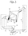
- the proposed method includes performing a step of recording of a hologram 125 of a keyboard 119 of a mobile handset.
- the arrangement for performing such a step of recording is shown in figure 3 , and comprises a laser source 111, generating a laser beam 112 that impinges on a beam splitter mirror 113.
- Such a beam splitter mirror 113 generates a beam 114 and a reference beam 115, that are coherent.
- the beam 114 is conveyed by a mirror system 116 including deflecting mirrors and a lens on the keyboard 119.
- a keyboard 119 reflects the beam 114 originating a diffused beam 124, that impinges on a photographic plate 120.
- a mirror system 121 reflects the reference beam 115 through an optical system 123, for example a beam steerer of known type, on the photographic plate 120.
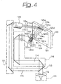
- the proposed method provides for a step of recording on the photographic plate 120 a plurality of holograms 125a, 125b, 125c, 125d, corresponding to different actuator positions 130a, 130b, 130c, 130d.
- the model actuator indicated with reference 135 in figure 4 , can be a finger or an indicator such as a plastic cylinder or an equivalent object.
- Such actuator positions 130a, 130b, 130c, 130d are positions in space corresponding to the keys of the keyboard 119, and then illuminated by the beam 114, thus recording holograms in different areas on the plate 120.
- different reference beams indicated with 115a, 115b, 115c, 115d in figure 4 , are used.
- Said different reference beams 115a, 115b, 115c, 115d are directed sequentially in time by means of the optical system 123 to the different areas on the plate 120 where the beam 114 has been diffused by the actuator in each different actuator position 130a, 130b, 130c, 130d.
- Such different reference beams 115a, 115b, 115c, 115d have a size that covers a limited area on the plate 120 carrying the holograms, such a limited area being fairly smaller than the area covered by the hologram 125 of the keyboard.
- the finger positions correspond to a spatial position on the plate 120, on which the position of the different keys are perceived by a user observing through the plate 120.
- the size of such different reference beams 115a, 115b, 115c, 115d also correspond substantially to the size of the keys of the keyboard.
- a single reference beam among the different reference beams 115a, 115b, 115c, 115d is projected at a time for each among the actuators positions 130a, 130b, 130c, 130d, or key of the keyboard 119.
- FIG 4 only four actuator positions have been shown for the sake of simplicity, while it is clear that a hologram of an actuator can be recorded for each key.
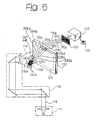
- the input device is ready for being operated by a user, as shown in figure 5 .
- Interaction by a user with the keyboard 119 is based on a reading step of the finger position of the user by the arrangement shown in figure 5 .
- Such an arrangement requires also the part of the optical arrangement shown in figure 3 that is devoted to reference beam generation, i.e. the mirror system 121 for reproducing a virtual image 126 of the keyboard 119.
- Such a mirror system 121 is not shown in figure 5 for sake of simplicity.
- the virtual image 126 of the keyboard 119 is projected by conventionally illuminating the plate 120 with the reference beam 115, so that the user can see such a virtual image 126 through the plate 120.
- the area where the virtual image is to be seen is further illuminated by a beam 114, generated by laser source 111 and conveyed by mirror system 116.
- the user interposes a finger in the spatial position in which a key of the virtual image 126 of the keyboard is perceived by the observer, this corresponds to selectively placing an actuator 135 in the positions 130a, 130b, 130c or 130d in the path of the beam 114.
- Light scattered by the finger is comprised of the object beams 200a, 200b, 200c, 200d, respectively, depending on the position of the actuator.
- each object beam is able to selectively generate the corresponding reference beam 115a, 115b, 115c, 115d through the interaction with the plate 120.
- the reference beam among beams 115a, 115b, 115c, 115d, that is generated through the plate 120 will impinge on a CCD array 131 or, in general, on a photodetector arrangement, in a position that is specific of that reference beam.
- the CCD array 131 is able to detect which reference beam among plurality of reference beams 115a, 115b, 115c, 115d has been generated and to send such an information to a suitable microprocessor 132, that provides for operating the real actuation, i.e. is suitably programmed for transmitting a command string corresponding to the key of keyboard 119 that has been virtually depressed.
- the microprocessor 132 can also drive a suitable speaker 133, in order to generate a 'click' sound, in order to supply a feedback to the user about the actuated selection, and, in particular about the interaction with the image 126 of the keyboard 119.
- a feedback can be also a visual feedback.
- conjugate beams are generated during the interaction with the virtual image 126.
- Such conjugate beams can be time correlated with the corresponding reference beams in order to increase the signal to noise ratio or can be used as a alternate or backup reading system.
- an apparatus and method for holographic control have thus been described herein that permit for a holographic representation of an input device and a direct interaction with such a holographic representation.
- the instant description discloses an arrangement for recording and reading holograms. Operation of that arrangement is based on recording separately on a holographic support a hologram of the input device and one or more holograms of an actuator suitable for operating the input device and letting the user interact with the holographic image of the input device, in order to have generation of a suitable reference beam if a real actuator, i.e. a user's finger, is placed in a position on the holographic image of the input device corresponding to a position in which a hologram of an actuator was previously recorded.
- a real actuator i.e. a user's finger
- This arrangement differs from methods of image recognition using Fourier holography, since it does not require optical elements to transform and antitransform the images.
- the proposed arrangement does not require volumetric position sensors or devices.
- the present invention requires only a simple sensor, as for example a CCD or a bank of few photo-diodes.
- the prerecording step can be operated in different ways, for what concerns placement of actuators.
- a plurality of actuators can be provided and all such actuators can be placed at the same time on the corresponding keys.
- Multiple reference beams can be thus addressed on the corresponding plate areas, through a suitable reference beam splitting device.
- volume holography can be used.
- such holograms are recorded in the same area of the holographic support, varying however the incidence angle of the different reference beams associated to each of such holograms.
- Each reference beam with its own incidence angle will be associated to a specific hologram and a specific virtual image.
- a holographic support' represented as a single plate
- such a holographic support can comprise a plurality of holographic supports, e.g. a holographic support where the input hologram is recorded on a first plate and the actuator holograms are recorded on a second plate.
- Such first plate and second plate can be recorded separately and assembled in the final input system.
- actuators hologram corresponding to different types of actuator (e.g. big fingers and little fingers) that are assembled with the plate carrying the keyboard hologram at user's desire.
Landscapes
- Engineering & Computer Science (AREA)
- General Engineering & Computer Science (AREA)
- Physics & Mathematics (AREA)
- General Physics & Mathematics (AREA)
- Theoretical Computer Science (AREA)
- Multimedia (AREA)
- Human Computer Interaction (AREA)
- Holo Graphy (AREA)
Claims (24)
- Procédé pour entrer des commandes, comprenant les opérations consistant à :générer une image virtuelle (26 ; 126) d'un dispositif d'entrée (19 ; 119) en illuminant un hologramme (25 ; 125) dudit dispositif d'entrée (19 ; 119) au moyen d'un faisceau de référence correspondant (15 ; 115), ledit hologramme (25 ; 125) étant préenregistré sur un support holographique (20 ; 120),détecter optiquement une position (130a, 130b, 130c, 130d) d'au moins un actionneur (135) pour faire fonctionner ledit dispositif d'entrée (119) par rapport à ladite image virtuelle (25 ; 125) dudit dispositif d'entrée (19 ; 119), etémettre au moins un signal de commande correspondant à ladite position (130a, 130b, 130c, 130d) dudit au moins un actionneur (135) qui a été détectée optiquement,caractérisé en ce que ladite opération de détection optique comprend les étapes consistant à :fournir au moins un hologramme d'actionnement (125a, 125b, 125c, 125d), correspondant audit au moins un actionneur (135) qui est placé à une position spécifiée (130a, 130b, 130c, 130d) par rapport à ladite imagevirtuelle (126) dudit dispositif d'entrée (119),illuminer ledit au moins un actionneur avec un faisceau (114), pour obtenir une dispersion dans un faisceau d'objet correspondant (200a, 200b, 200c, 200d),interagir avec un hologramme d'actionnement (125a, 125b, 125c, 125d) à travers le faisceau d'objet correspondant (200a, 200b, 200c, 200d),générer un faisceau de détection d'actionnement respectif (115a, 115b, 115c, 115d) à travers ladite interaction, etdétecter ledit faisceau de détection d'actionnement respectif (115a, 115b, 115c, 115d) pour émettre ledit signal de commande.
- Procédé selon la revendication 1, caractérisé en ce qu'il comprend une étape de pré-enregistrement sur ledit support holographique (120) dudit au moins un hologramme d'actionnement (125a, 125b, 125c, 125d).
- Procédé selon la revendication 2, caractérisé en ce que ladite étape de pré-enregistrement comprend le placement dudit au moins un actionneur (135) à la fois à ladite position spécifiée (130a, 130b, 130c, 130d) par rapport à ladite image virtuelle (126) et l'enregistrement d'un hologramme d'actionnement correspondant (125a, 125b, 125c, 125d) à travers un faisceau de détection correspondant (115a, 115b, 115c, 115d).
- Procédé selon la revendication 1, caractérisé en ce que ledit hologramme d'actionnement (125a, 125b, 125c, 125d) est situé dans une zone différente dudit support holographique (120) par rapport à la zone dans laquelle l'hologramme (125) du dispositif d'entrée (119) est enregistré.
- Procédé selon la revendication 1, caractérisé en ce que la zone utilisée par ledit hologramme d'actionnement (125a, 125b, 125c, 125d) est de taille sensiblement plus petite que celle de la zone dans laquelle l'hologramme (125) du dispositif d'entrée (119) est enregistré.
- Procédé selon la revendication 1, caractérisé en ce que ledit faisceau de détection d'actionnement (115a, 115b, 115c, 115d) correspond à un faisceau de référence utilisé pour enregistrer ledit hologramme d'actionnement (125a, 125b, 125c, 125d).
- Procédé selon la revendication 2, caractérisé en ce que ledit faisceau de détection d'actionnement (115a, 115b, 115c, 115d) correspond à un faisceau conjugué (Ec ) d'un faisceau de référence utilisé pour enregistrer ledit hologramme d'actionnement (125a, 125b, 125c, 125d).
- Procédé selon la revendication 7, caractérisé en ce qu'un faisceau conjugué dudit faisceau de référence utilisé pour enregistrer ledit hologramme d'actionnement (125a, 125b, 125c, 125d) est également détecté.
- Procédé selon la revendication 1, caractérisé en ce que ledit dispositif d'entrée (119) est un clavier.
- Procédé selon la revendication 1, caractérisé en ce que ledit hologramme d'actionnement (125a, 125b, 125c, 125d) a une taille comparable à celle d'une touche du dispositif d'entrée (119).
- Procédé selon la revendication 1, caractérisé en ce qu'il comprend en outre l'opération consistant à fournir une rétroaction audio ou visuelle de ladite étape de détection dudit faisceau de détection d'actionnement respectif (115a, 115b, 115c, 115d) pour émettre ledit signal de commande.
- Procédé selon la revendication 1, caractérisé en ce qu'il comprend l'étape consistant à enregistrer ledit hologramme du dispositif d'entrée et ledit hologramme d'actionnement sur des supports holographiques distincts et à assembler lesdits supports de manière à former ledit support holographique (120).
- Procédé selon la revendication 1, caractérisé en ce que ladite pluralité d'hologrammes d'actionnement (125a, 125b, 125c, 125d) est enregistrée dans une même zone du support holographique (120) en faisant varier l'angle d'incidence des faisceaux de détection correspondants (115a, 115b, 115c, 115d) associés à chacun desdits hologrammes d'actionnement (125a, 125b, 125c, 125d).
- Système pour entrer des commandes, comprenant :un système optique (11, 21 ; 111, 121) pour générer une image virtuelle (26 ; 126) d'un dispositif d'entrée (19 ; 119) en illuminant un hologramme (25 ; 125) dudit dispositif d'entrée (19 ; 119) au moyen d'un faisceau de référence (15 ; 115), ledit hologramme (25 ; 125) étant préenregistré sur un support holographique (20 ; 120),un module de détection (116, 120, 131) pour détecter optiquement la position (130a, 130b, 130c, 130d) d'au moins un actionneur (135) pour faire fonctionner ledit dispositif d'entrée (119) par rapport à ladite image virtuelle (25 ; 125) dudit dispositif d'entrée (19 ; 119), etun module d'émission (132) pour émettre au moins un signal de commande correspondant à ladite position (130a, 130b, 130c, 130d) dudit au moins un actionneur (135) qui a été détectée optiquement, caractérisé en ce qu'il comprend :des hologrammes d'actionnement préenregistrés (125a, 125b, 125c, 125d) correspondant audit au moins un actionneur (135) qui sont placés à des positions spécifiées (130a, 130b, 130c, 130d) par rapport à ladite image virtuelle (126) dudit dispositif d'entrée (119),un autre système optique (111, 114, 116) pour illuminer ledit au moins un actionneur (135) pour obtenir une dispersion dans un faisceau d'objet correspondant (200a, 200b, 200c, 200d), dans lequell'hologramme d'actionnement (125a, 125b, 125c, 125d) est apte à interagir avec le faisceau d'objet correspondant (200a, 200b, 200c, 200d) pour générer un faisceau de détection d'actionnement respectif (115a, 115b, 115c, 115d), et dans lequelle module de détection (131) est apte à détecter ledit faisceau de détection d'actionnement respectif (115a, 115b, 115c, 115d) pour émettre ledit signal de commande.
- Système selon la revendication 14, caractérisé en ce que lesdits hologrammes d'actionnement préenregistrés (125a, 125b, 125c, 125d) sont préenregistrés sur ledit support holographique (20, 120).
- Système selon la revendication 14, caractérisé en ce que lesdits hologrammes d'actionnement préenregistrés (125a, 125b, 125c, 125d) sont enregistrés séparément l'un de l'autre à travers des faisceaux de référence correspondants (115a, 115b, 115c, 115d).
- Système selon la revendication 15, caractérisé en ce que ledit support holographique (120) porte différentes zones pour enregistrer lesdits hologrammes d'actionnement (125a, 125b, 125c, 125d) par rapport à la zone pour enregistrer l'hologramme (125) du dispositif d'entrée (119).
- Système selon la revendication 15, caractérisé en ce que la zone utilisée par ledit hologramme d'actionnement (125a, 125b, 125c, 125d) est de taille sensiblement plus petite que celle de la zone dans laquelle l'hologramme (125) du dispositif d'entrée (119) est enregistré.
- Système selon la revendication 14, caractérisé en ce que ledit dispositif d'entrée (119) est un clavier.
- Système selon la revendication 15, caractérisé en ce que ledit hologramme d'actionnement (125a, 125b, 125c, 125d) a une taille similaire à celle d'une touche du dispositif d'entrée (119).
- Système selon la revendication 14, caractérisé en ce que ledit module pour détecter le faisceau de détection d'actionnement respectif (115a, 115b, 115c, 115d) est un réseau de dispositifs à couplage de charge.
- Système selon la revendication 14, caractérisé en ce que ledit module de détection comprend un module (133) pour une rétroaction audio ou visuelle de la détection dudit faisceau de détection d'actionnement (115a, 115b, 115c, 115d).
- Système selon la revendication 14, caractérisé en ce que ledit support holographique (120) comprend une pluralité de supports holographiques assemblés.
- Système selon la revendication 14, caractérisé en ce que ledit support holographique (120) porte ladite pluralité d'hologrammes d'actionnement (125a, 125b, 125c, 125d) dans une même zone.
Applications Claiming Priority (1)
| Application Number | Priority Date | Filing Date | Title |
|---|---|---|---|
| PCT/EP2004/007105 WO2006002666A1 (fr) | 2004-06-30 | 2004-06-30 | Saisie d'informations au moyen de techniques holographiques |
Publications (2)
| Publication Number | Publication Date |
|---|---|
| EP1761839A1 EP1761839A1 (fr) | 2007-03-14 |
| EP1761839B1 true EP1761839B1 (fr) | 2008-08-13 |
Family
ID=34958046
Family Applications (1)
| Application Number | Title | Priority Date | Filing Date |
|---|---|---|---|
| EP04740484A Expired - Lifetime EP1761839B1 (fr) | 2004-06-30 | 2004-06-30 | Saisie d'informations au moyen de techniques holographiques |
Country Status (5)
| Country | Link |
|---|---|
| US (1) | US8089456B2 (fr) |
| EP (1) | EP1761839B1 (fr) |
| AT (1) | ATE404911T1 (fr) |
| DE (1) | DE602004015856D1 (fr) |
| WO (1) | WO2006002666A1 (fr) |
Families Citing this family (7)
| Publication number | Priority date | Publication date | Assignee | Title |
|---|---|---|---|---|
| US8477098B2 (en) | 2007-10-31 | 2013-07-02 | Gene S. Fein | Method and apparatus for user interface of input devices |
| US20090109215A1 (en) * | 2007-10-31 | 2009-04-30 | Fein Gene S | Method and apparatus for user interface communication with an image manipulator |
| US11449146B2 (en) | 2015-06-10 | 2022-09-20 | Wayne Patrick O'Brien | Interactive holographic human-computer interface |
| US10720082B1 (en) | 2016-09-08 | 2020-07-21 | Ctskh, Llc | Device and system to teach stem lessons using hands-on learning method |
| EP3556702A1 (fr) | 2018-03-13 | 2019-10-23 | Otis Elevator Company | Panneau de commande de cabine de réalité augmentée |
| US11188154B2 (en) * | 2018-05-30 | 2021-11-30 | International Business Machines Corporation | Context dependent projection of holographic objects |
| US11344655B2 (en) * | 2020-06-29 | 2022-05-31 | John T. Daugirdas | Holographic control system for hemodialysis |
Family Cites Families (13)
| Publication number | Priority date | Publication date | Assignee | Title |
|---|---|---|---|---|
| JPS491047B1 (fr) * | 1969-07-04 | 1974-01-11 | ||
| US5266531A (en) * | 1991-01-30 | 1993-11-30 | Cordata Incorporated | Dynamic holographic display with cantilever |
| US5479257A (en) | 1993-04-05 | 1995-12-26 | Olympus Optical Co., Ltd. | Method of and apparatus for detecting object position using a fourier transform of the object image and processing system using the same |
| DE4492865T1 (de) * | 1993-04-28 | 1996-04-25 | Mcpheters | Holographische Benutzer-Schnittstelle |
| GB9505664D0 (en) | 1995-03-21 | 1995-05-10 | Central Research Lab Ltd | An interactive display and input device |
| US6031519A (en) * | 1997-12-30 | 2000-02-29 | O'brien; Wayne P. | Holographic direct manipulation interface |
| US6330088B1 (en) * | 1998-02-27 | 2001-12-11 | Zebra Imaging, Inc. | Method and apparatus for recording one-step, full-color, full-parallax, holographic stereograms |
| US6611252B1 (en) * | 2000-05-17 | 2003-08-26 | Dufaux Douglas P. | Virtual data input device |
| US6650318B1 (en) * | 2000-10-13 | 2003-11-18 | Vkb Inc. | Data input device |
| US20020070921A1 (en) | 2000-12-13 | 2002-06-13 | Feldman Stephen E. | Holographic keyboard |
| US6625100B2 (en) * | 2001-03-20 | 2003-09-23 | Imation Corp. | Tracking techniques for holographic data storage media |
| US7158228B2 (en) * | 2002-07-25 | 2007-01-02 | California Institute Of Technology | Holographic imaging spectrometer |
| US7671843B2 (en) * | 2002-11-12 | 2010-03-02 | Steve Montellese | Virtual holographic input method and device |
-
2004
- 2004-06-30 WO PCT/EP2004/007105 patent/WO2006002666A1/fr not_active Ceased
- 2004-06-30 DE DE602004015856T patent/DE602004015856D1/de not_active Expired - Lifetime
- 2004-06-30 US US11/631,078 patent/US8089456B2/en active Active
- 2004-06-30 AT AT04740484T patent/ATE404911T1/de not_active IP Right Cessation
- 2004-06-30 EP EP04740484A patent/EP1761839B1/fr not_active Expired - Lifetime
Also Published As
| Publication number | Publication date |
|---|---|
| DE602004015856D1 (de) | 2008-09-25 |
| EP1761839A1 (fr) | 2007-03-14 |
| ATE404911T1 (de) | 2008-08-15 |
| US8089456B2 (en) | 2012-01-03 |
| WO2006002666A1 (fr) | 2006-01-12 |
| US20090184851A1 (en) | 2009-07-23 |
Similar Documents
| Publication | Publication Date | Title |
|---|---|---|
| KR100942079B1 (ko) | 인증 시스템 및 방법 | |
| JP5113922B2 (ja) | ホログラフィックヒューマンマシンインタフェース | |
| TWI540400B (zh) | And a method and a device for generating a thin body grating stack and a beam combiner for a monolithic display | |
| US6486982B1 (en) | System for making a hologram of an image by manipulating object beam characteristics to reflect image data | |
| US7605961B2 (en) | Enhanced environment visualization using holographic stereograms | |
| US20110249309A1 (en) | Compact holograhic human-machine interface | |
| EP2247982B1 (fr) | Systèmes optiques sans rétroaction, se recouvrant partiellement, couplés de manière non rigide permettant un filtrage spatial des motifs optiques par transformée de fourier et une caractérisation du contenu de forme d'image | |
| EP1933309A1 (fr) | Procédé de recherche | |
| Weber et al. | Novel implementation of nonlinear joint transform correlators in optical security and validation | |
| JP4342311B2 (ja) | 導波路多層ホログラフィックデータストレージ | |
| EP1761839B1 (fr) | Saisie d'informations au moyen de techniques holographiques | |
| TW479250B (en) | System and method for steering fresnel region data to access data locations in a holographic memory | |
| US4120569A (en) | Method and apparatus for the holographic storage and retrieval | |
| US8690339B2 (en) | Complete digital holographic image sensor-projector computing unit having a modulator for receiving a fourier image | |
| CA2257434A1 (fr) | Procede et appareil de production d'une image holographique cachee | |
| US5687012A (en) | Hologram in which a plurality of areas are set and holography system to which hologram is applied | |
| JPH09222954A (ja) | 拡散ホログラムタッチパネル | |
| Kick et al. | Sequential and non-sequential simulation of volume holographic gratings | |
| WO2002067061A1 (fr) | Dispositif et procede de reproduction d'hologramme | |
| JPS60181877A (ja) | 光学的相関器 | |
| JP3713812B2 (ja) | 回折格子パターン作製装置 | |
| CA2727902A1 (fr) | Systeme d'holographie numerique pour l'enregistrement et la reconstruction d'hologrammes traites par ordinateur | |
| JPH03500694A (ja) | 単一面構造の光学相関器 | |
| Weber et al. | Novel implementation of nonlinear joint transform correlators in optical security and validation | |
| Bigler | Holographic Optical Elements and Their Applications in Waveguide Display Technologies |
Legal Events
| Date | Code | Title | Description |
|---|---|---|---|
| PUAI | Public reference made under article 153(3) epc to a published international application that has entered the european phase |
Free format text: ORIGINAL CODE: 0009012 |
|
| 17P | Request for examination filed |
Effective date: 20061221 |
|
| AK | Designated contracting states |
Kind code of ref document: A1 Designated state(s): AT BE BG CH CY CZ DE DK EE ES FI FR GB GR HU IE IT LI LU MC NL PL PT RO SE SI SK TR |
|
| 17Q | First examination report despatched |
Effective date: 20070507 |
|
| DAX | Request for extension of the european patent (deleted) | ||
| GRAP | Despatch of communication of intention to grant a patent |
Free format text: ORIGINAL CODE: EPIDOSNIGR1 |
|
| GRAS | Grant fee paid |
Free format text: ORIGINAL CODE: EPIDOSNIGR3 |
|
| GRAA | (expected) grant |
Free format text: ORIGINAL CODE: 0009210 |
|
| AK | Designated contracting states |
Kind code of ref document: B1 Designated state(s): AT BE BG CH CY CZ DE DK EE ES FI FR GB GR HU IE IT LI LU MC NL PL PT RO SE SI SK TR |
|
| REG | Reference to a national code |
Ref country code: GB Ref legal event code: FG4D |
|
| REG | Reference to a national code |
Ref country code: CH Ref legal event code: EP |
|
| REG | Reference to a national code |
Ref country code: IE Ref legal event code: FG4D |
|
| REF | Corresponds to: |
Ref document number: 602004015856 Country of ref document: DE Date of ref document: 20080925 Kind code of ref document: P |
|
| REG | Reference to a national code |
Ref country code: SE Ref legal event code: TRGR |
|
| PG25 | Lapsed in a contracting state [announced via postgrant information from national office to epo] |
Ref country code: NL Free format text: LAPSE BECAUSE OF FAILURE TO SUBMIT A TRANSLATION OF THE DESCRIPTION OR TO PAY THE FEE WITHIN THE PRESCRIBED TIME-LIMIT Effective date: 20080813 Ref country code: ES Free format text: LAPSE BECAUSE OF FAILURE TO SUBMIT A TRANSLATION OF THE DESCRIPTION OR TO PAY THE FEE WITHIN THE PRESCRIBED TIME-LIMIT Effective date: 20081124 |
|
| PG25 | Lapsed in a contracting state [announced via postgrant information from national office to epo] |
Ref country code: SI Free format text: LAPSE BECAUSE OF FAILURE TO SUBMIT A TRANSLATION OF THE DESCRIPTION OR TO PAY THE FEE WITHIN THE PRESCRIBED TIME-LIMIT Effective date: 20080813 Ref country code: FI Free format text: LAPSE BECAUSE OF FAILURE TO SUBMIT A TRANSLATION OF THE DESCRIPTION OR TO PAY THE FEE WITHIN THE PRESCRIBED TIME-LIMIT Effective date: 20080813 Ref country code: AT Free format text: LAPSE BECAUSE OF FAILURE TO SUBMIT A TRANSLATION OF THE DESCRIPTION OR TO PAY THE FEE WITHIN THE PRESCRIBED TIME-LIMIT Effective date: 20080813 |
|
| PG25 | Lapsed in a contracting state [announced via postgrant information from national office to epo] |
Ref country code: BE Free format text: LAPSE BECAUSE OF FAILURE TO SUBMIT A TRANSLATION OF THE DESCRIPTION OR TO PAY THE FEE WITHIN THE PRESCRIBED TIME-LIMIT Effective date: 20080813 |
|
| PG25 | Lapsed in a contracting state [announced via postgrant information from national office to epo] |
Ref country code: DK Free format text: LAPSE BECAUSE OF FAILURE TO SUBMIT A TRANSLATION OF THE DESCRIPTION OR TO PAY THE FEE WITHIN THE PRESCRIBED TIME-LIMIT Effective date: 20080813 Ref country code: BG Free format text: LAPSE BECAUSE OF FAILURE TO SUBMIT A TRANSLATION OF THE DESCRIPTION OR TO PAY THE FEE WITHIN THE PRESCRIBED TIME-LIMIT Effective date: 20081113 |
|
| PG25 | Lapsed in a contracting state [announced via postgrant information from national office to epo] |
Ref country code: PT Free format text: LAPSE BECAUSE OF FAILURE TO SUBMIT A TRANSLATION OF THE DESCRIPTION OR TO PAY THE FEE WITHIN THE PRESCRIBED TIME-LIMIT Effective date: 20090113 Ref country code: CZ Free format text: LAPSE BECAUSE OF FAILURE TO SUBMIT A TRANSLATION OF THE DESCRIPTION OR TO PAY THE FEE WITHIN THE PRESCRIBED TIME-LIMIT Effective date: 20080813 Ref country code: RO Free format text: LAPSE BECAUSE OF FAILURE TO SUBMIT A TRANSLATION OF THE DESCRIPTION OR TO PAY THE FEE WITHIN THE PRESCRIBED TIME-LIMIT Effective date: 20080813 Ref country code: SK Free format text: LAPSE BECAUSE OF FAILURE TO SUBMIT A TRANSLATION OF THE DESCRIPTION OR TO PAY THE FEE WITHIN THE PRESCRIBED TIME-LIMIT Effective date: 20080813 |
|
| PLBE | No opposition filed within time limit |
Free format text: ORIGINAL CODE: 0009261 |
|
| STAA | Information on the status of an ep patent application or granted ep patent |
Free format text: STATUS: NO OPPOSITION FILED WITHIN TIME LIMIT |
|
| 26N | No opposition filed |
Effective date: 20090514 |
|
| PG25 | Lapsed in a contracting state [announced via postgrant information from national office to epo] |
Ref country code: EE Free format text: LAPSE BECAUSE OF FAILURE TO SUBMIT A TRANSLATION OF THE DESCRIPTION OR TO PAY THE FEE WITHIN THE PRESCRIBED TIME-LIMIT Effective date: 20080813 |
|
| PG25 | Lapsed in a contracting state [announced via postgrant information from national office to epo] |
Ref country code: MC Free format text: LAPSE BECAUSE OF NON-PAYMENT OF DUE FEES Effective date: 20090630 |
|
| REG | Reference to a national code |
Ref country code: CH Ref legal event code: PL |
|
| PG25 | Lapsed in a contracting state [announced via postgrant information from national office to epo] |
Ref country code: CH Free format text: LAPSE BECAUSE OF NON-PAYMENT OF DUE FEES Effective date: 20090630 Ref country code: IE Free format text: LAPSE BECAUSE OF NON-PAYMENT OF DUE FEES Effective date: 20090630 Ref country code: LI Free format text: LAPSE BECAUSE OF NON-PAYMENT OF DUE FEES Effective date: 20090630 |
|
| PG25 | Lapsed in a contracting state [announced via postgrant information from national office to epo] |
Ref country code: PL Free format text: LAPSE BECAUSE OF FAILURE TO SUBMIT A TRANSLATION OF THE DESCRIPTION OR TO PAY THE FEE WITHIN THE PRESCRIBED TIME-LIMIT Effective date: 20080813 |
|
| PG25 | Lapsed in a contracting state [announced via postgrant information from national office to epo] |
Ref country code: GR Free format text: LAPSE BECAUSE OF FAILURE TO SUBMIT A TRANSLATION OF THE DESCRIPTION OR TO PAY THE FEE WITHIN THE PRESCRIBED TIME-LIMIT Effective date: 20081114 |
|
| PG25 | Lapsed in a contracting state [announced via postgrant information from national office to epo] |
Ref country code: LU Free format text: LAPSE BECAUSE OF NON-PAYMENT OF DUE FEES Effective date: 20090630 |
|
| PG25 | Lapsed in a contracting state [announced via postgrant information from national office to epo] |
Ref country code: HU Free format text: LAPSE BECAUSE OF FAILURE TO SUBMIT A TRANSLATION OF THE DESCRIPTION OR TO PAY THE FEE WITHIN THE PRESCRIBED TIME-LIMIT Effective date: 20090214 |
|
| PG25 | Lapsed in a contracting state [announced via postgrant information from national office to epo] |
Ref country code: TR Free format text: LAPSE BECAUSE OF FAILURE TO SUBMIT A TRANSLATION OF THE DESCRIPTION OR TO PAY THE FEE WITHIN THE PRESCRIBED TIME-LIMIT Effective date: 20080813 |
|
| PG25 | Lapsed in a contracting state [announced via postgrant information from national office to epo] |
Ref country code: CY Free format text: LAPSE BECAUSE OF FAILURE TO SUBMIT A TRANSLATION OF THE DESCRIPTION OR TO PAY THE FEE WITHIN THE PRESCRIBED TIME-LIMIT Effective date: 20080813 |
|
| REG | Reference to a national code |
Ref country code: FR Ref legal event code: PLFP Year of fee payment: 13 |
|
| REG | Reference to a national code |
Ref country code: FR Ref legal event code: PLFP Year of fee payment: 14 |
|
| REG | Reference to a national code |
Ref country code: FR Ref legal event code: PLFP Year of fee payment: 15 |
|
| P01 | Opt-out of the competence of the unified patent court (upc) registered |
Effective date: 20230529 |
|
| P02 | Opt-out of the competence of the unified patent court (upc) changed |
Effective date: 20230602 |
|
| PGFP | Annual fee paid to national office [announced via postgrant information from national office to epo] |
Ref country code: FR Payment date: 20230626 Year of fee payment: 20 Ref country code: DE Payment date: 20230626 Year of fee payment: 20 |
|
| PGFP | Annual fee paid to national office [announced via postgrant information from national office to epo] |
Ref country code: SE Payment date: 20230627 Year of fee payment: 20 |
|
| PGFP | Annual fee paid to national office [announced via postgrant information from national office to epo] |
Ref country code: IT Payment date: 20230620 Year of fee payment: 20 Ref country code: GB Payment date: 20230627 Year of fee payment: 20 |
|
| REG | Reference to a national code |
Ref country code: DE Ref legal event code: R071 Ref document number: 602004015856 Country of ref document: DE |
|
| PG25 | Lapsed in a contracting state [announced via postgrant information from national office to epo] |
Ref country code: GB Free format text: LAPSE BECAUSE OF EXPIRATION OF PROTECTION Effective date: 20240629 |
|
| REG | Reference to a national code |
Ref country code: GB Ref legal event code: PE20 Expiry date: 20240629 |
|
| REG | Reference to a national code |
Ref country code: SE Ref legal event code: EUG |
|
| PG25 | Lapsed in a contracting state [announced via postgrant information from national office to epo] |
Ref country code: GB Free format text: LAPSE BECAUSE OF EXPIRATION OF PROTECTION Effective date: 20240629 |