EP1761124B1 - Arrangement for securing a handle bar to a portable tool - Google Patents
Arrangement for securing a handle bar to a portable tool Download PDFInfo
- Publication number
- EP1761124B1 EP1761124B1 EP05754837A EP05754837A EP1761124B1 EP 1761124 B1 EP1761124 B1 EP 1761124B1 EP 05754837 A EP05754837 A EP 05754837A EP 05754837 A EP05754837 A EP 05754837A EP 1761124 B1 EP1761124 B1 EP 1761124B1
- Authority
- EP
- European Patent Office
- Prior art keywords
- sleeve
- tube
- holding device
- handle bar
- layer
- Prior art date
- Legal status (The legal status is an assumption and is not a legal conclusion. Google has not performed a legal analysis and makes no representation as to the accuracy of the status listed.)
- Expired - Lifetime
Links
Images


Classifications
-
- A—HUMAN NECESSITIES
- A01—AGRICULTURE; FORESTRY; ANIMAL HUSBANDRY; HUNTING; TRAPPING; FISHING
- A01D—HARVESTING; MOWING
- A01D34/00—Mowers; Mowing apparatus of harvesters
- A01D34/835—Mowers; Mowing apparatus of harvesters specially adapted for particular purposes
- A01D34/90—Mowers; Mowing apparatus of harvesters specially adapted for particular purposes for carrying by the operator
- A01D34/905—Vibration dampening means
-
- B—PERFORMING OPERATIONS; TRANSPORTING
- B25—HAND TOOLS; PORTABLE POWER-DRIVEN TOOLS; MANIPULATORS
- B25F—COMBINATION OR MULTI-PURPOSE TOOLS NOT OTHERWISE PROVIDED FOR; DETAILS OR COMPONENTS OF PORTABLE POWER-DRIVEN TOOLS NOT PARTICULARLY RELATED TO THE OPERATIONS PERFORMED AND NOT OTHERWISE PROVIDED FOR
- B25F5/00—Details or components of portable power-driven tools not particularly related to the operations performed and not otherwise provided for
- B25F5/006—Vibration damping means
Definitions
- the claimed invention relates to a portable power tool with a handle bar secured to a tube of the tool by a holding device placed between the handle bar and the tube.
- Clearing saws, trimmers, brush cutters and hedge trimmers are frequently used in order to facilitate work in forests and gardens. These power_tools are available in several different sizes and shapes, each of them optimized for the work that the tool is supposed to be used for and to meet the requirements from the operator.
- Clearing saws, trimmers, brush cutters and hedge trimmers comprises an engine and there to related components placed in one end of a tube.
- the drive shaft extends inside the tube from the engine to the other end of the tube where it is connected to the working tool.
- the length of the tube and the working tool for example a trimmer head for a cutting filament, a saw blade, a guide bar and saw chain or a device for a hedge trimmer, are selected for the specific use of the product.
- these tools are carried by a harness placed around the shoulders of the operator.
- the tool is attached to a strap extending from the harness so that the strap and the harness support the weight of the tool.
- the tools are also provided with a handle bar secured to the tool somewhere along the tube by a holding device. One end of the holding device is clamped to the tube and at the other end the handle bar is secured. The handle bar is used by the operator for maneuvering the working tool during use of the power tool.
- the power tool comprises several components that are moving when the tool is running. These components generate vibrations in the tube that are transferred to the handle bar. These vibrations are consequently also transferred to the hands of the operator via the handle bar, which is very uncomfortable for the operator.
- a handle bar arrangement that improves the working conditions for the operator is therefore requested.
- the portable power tool includes an elongate tube, a power source placed in a first end of the tube, a working tool placed in a second end of the tube and a handle bar secured to the tube by a holding device placed between the handle bar and the tube.
- a sleeve is fixed around the tube, the inside of said sleeve is shaped to match the cross section of the tube and the outside of said sleeve has a non-circular shape.
- the sleeve further is at least partially surrounded by a layer of an elastic material, and the holding device is provided with a cavity with a similar shape as the outside of the sleeve and is arranged to be clamped around the sleeve and layer of elastic material.
- the layer of elastic material reduces the vibration transferred from the tool to the handle bar and the non- circular shaped outside of the sleeve and cavity keeps the holding device in the intended position even though there is an elastic material between the sleeve and the holding device.
- One preferred embodiment of the invention comprises an elastic layer that surrounds the entire sleeve.
- the thickness of the layer is between 2 to 15 mm.
- An elastic layer with bigger thickness is more efficient in reducing the amount of vibrations transferred to the handle.
- a thick elastic layer however makes it more complicated to clamp the holding device around the sleeve and the elastic layer in a reliably manner.
- the non-circular shape of the outside of the sleeve, and consequently also the elastic layer makes it possible to fasten the holding device since the non-circular shape of the sleeve, the elastic layer and the section of the holding device that surrounds the sleeve and elastic layer will prevent movements between the sleeve and the holding device.
- the claimed invention therefore reduces the amount of vibrations transferred to the handle bar and offers reliable fastening of the handle bar to the tube.
- the tube is normally circular but other shapes may be used.
- a non-circular shape of the tube and the inside of the sleeve is a more complicated solution but it is an efficient solution that avoids movements between the tube and the sleeve.
- the outside of the sleeve and the corresponding section of the holding device are preferably oval shaped.
- the oval shaped sleeve and cavity in the holding device is easy to manufacture.
- the oval shape also makes it possible to mount the arrangement on the tube in an easy and efficient way.
- the power tool comprises a power source 11, normally a combustion engine, and related components, like for example fuel tank, muffler and a starting device placed in one end of a tube 12.
- the tube extends in longitudinal direction of the tool. The length of the tube depends on which type of work the tool is designed for. In the opposite end as the engine a not illustrated working tool is placed.
- the working tool is selected for the specific work that the tool will be used for. Examples of working tools are hedge trimmer blades, a guide bar with a saw chain, a cutting blade, or a filament cutter.
- a handle bar 14 is attached to the tube 12 somewhere along the tube 12 in order to make it possible for the operator to maneuver the tool 10.
- the handle bar 14 is secured to the tube 12 by a holding device 15.
- Tools provided with a handle bar 14 are supported by a harness or strap extending around the shoulders of the operator.
- the harness or strap is attached to a loop 13 secured to the tool.
- a sleeve 16 is fixed around the tube 12.
- the tube 12 has a circular cross section and the inside 25 of the sleeve 16 has a similar shape as the tube 12.
- the sleeve 16 is clamped to the tube 12 by a two screws 17 placed in the ends of the sleeve 16.
- the outside 18 of the sleeve 16 has a non-circular shape. In the illustrated embodiment the outside 18 of the sleeve 16 is oval but all other non-circular shapes could be used.
- a layer 19 covering substantially the entire circumference of the oval section of the sleeve 16 surrounds the sleeve 16.
- the layer 19 has a substantially constant thickness in radial direction around the sleeve 16 and is made of an elastic material.
- the elastic material will reduce the amount of vibrations transferred from the tool 10 to the handle bar 14.
- the thickness of the elastic layer is between 2 and 15 millimeters but to ensure a satisfying reduction of vibrations in the handle bar 14 the elastic layer 19 should be at least 3 millimeters and made of rubber or a material with similar features.
- the elastic layer 19 is surrounded by a cavity 21 formed in a first end 20 of the holding device 15.
- the cavity 21 has the same non-circular shape as the outside 18 of the sleeve 16.
- the non-circular shape of the outside 18 of the sleeve 16 and the cavity 21 in the holding device 15 keeps the holding device 15 in the predetermined position in relation to the sleeve 16 even though the sleeve 16 is surrounded by the elastic layer 19. This feature is essential for the claimed invention.
- the thickness of the elastic layer 19 as well as the shape of the outside 18 of the sleeve 16 and of the cavity may vary in axial direction along the tube 12 to avoid movements in axial direction between the sleeve 16, the elastic layer 19 and the holding device 15.
- a changed thickness of the elastic layer 19 or a change of the shape of the outside 18 of the sleeve 16 and of the cavity must however be accomplished by a similar change in the close contact layer or surface.
- the first end 20 of the holding device 15 comprises a first section 22 with one part of the cavity 21 and a second section 23 with the remaining part of the cavity 21.
- the two sections 22 and 23 are necessary to make it possible to mount and secure the holding device 15 around the sleeve 16 and the elastic layer 19.
- the second section 23 is fastened to the first section 22 integrated in the holding device 15 by four screws 24.
- the cavity could also be divided into more than two sections 22 and 23 if that for some reason is favorable. The number of screws could also vary.
- the handle bar is secured to the holding device.
Landscapes
- Life Sciences & Earth Sciences (AREA)
- Environmental Sciences (AREA)
- Engineering & Computer Science (AREA)
- Mechanical Engineering (AREA)
- Harvester Elements (AREA)
- Workshop Equipment, Work Benches, Supports, Or Storage Means (AREA)
- Portable Power Tools In General (AREA)
- Walking Sticks, Umbrellas, And Fans (AREA)
- Casings For Electric Apparatus (AREA)
Abstract
Description
- The claimed invention relates to a portable power tool with a handle bar secured to a tube of the tool by a holding device placed between the handle bar and the tube.
- Clearing saws, trimmers, brush cutters and hedge trimmers are frequently used in order to facilitate work in forests and gardens. These power_tools are available in several different sizes and shapes, each of them optimized for the work that the tool is supposed to be used for and to meet the requirements from the operator. Clearing saws, trimmers, brush cutters and hedge trimmers comprises an engine and there to related components placed in one end of a tube. The drive shaft extends inside the tube from the engine to the other end of the tube where it is connected to the working tool. The length of the tube and the working tool, for example a trimmer head for a cutting filament, a saw blade, a guide bar and saw chain or a device for a hedge trimmer, are selected for the specific use of the product.
- In order to improve the working conditions for the operator these tools are carried by a harness placed around the shoulders of the operator. The tool is attached to a strap extending from the harness so that the strap and the harness support the weight of the tool. The tools are also provided with a handle bar secured to the tool somewhere along the tube by a holding device. One end of the holding device is clamped to the tube and at the other end the handle bar is secured. The handle bar is used by the operator for maneuvering the working tool during use of the power tool.
- The power tool comprises several components that are moving when the tool is running. These components generate vibrations in the tube that are transferred to the handle bar. These vibrations are consequently also transferred to the hands of the operator via the handle bar, which is very uncomfortable for the operator.
- A handle bar arrangement that improves the working conditions for the operator is therefore requested.
- In view of the above, it is an objective to solve or at least reduce the problems discussed above.
- The objective is achieved with a portable power tool according to claim 1, in which the portable power tool includes an elongate tube, a power source placed in a first end of the tube, a working tool placed in a second end of the tube and a handle bar secured to the tube by a holding device placed between the handle bar and the tube. A sleeve is fixed around the tube, the inside of said sleeve is shaped to match the cross section of the tube and the outside of said sleeve has a non-circular shape. The sleeve further is at least partially surrounded by a layer of an elastic material, and the holding device is provided with a cavity with a similar shape as the outside of the sleeve and is arranged to be clamped around the sleeve and layer of elastic material.
- Thus, the amount of vibration transferred from the tool to the handle bar is reduced.
- The layer of elastic material reduces the vibration transferred from the tool to the handle bar and the non- circular shaped outside of the sleeve and cavity keeps the holding device in the intended position even though there is an elastic material between the sleeve and the holding device.
- One preferred embodiment of the invention comprises an elastic layer that surrounds the entire sleeve. The thickness of the layer is between 2 to 15 mm. An elastic layer with bigger thickness is more efficient in reducing the amount of vibrations transferred to the handle. A thick elastic layer however makes it more complicated to clamp the holding device around the sleeve and the elastic layer in a reliably manner. The non-circular shape of the outside of the sleeve, and consequently also the elastic layer, makes it possible to fasten the holding device since the non-circular shape of the sleeve, the elastic layer and the section of the holding device that surrounds the sleeve and elastic layer will prevent movements between the sleeve and the holding device. The claimed invention therefore reduces the amount of vibrations transferred to the handle bar and offers reliable fastening of the handle bar to the tube.
- The tube is normally circular but other shapes may be used. A non-circular shape of the tube and the inside of the sleeve is a more complicated solution but it is an efficient solution that avoids movements between the tube and the sleeve.
- The outside of the sleeve and the corresponding section of the holding device are preferably oval shaped. The oval shaped sleeve and cavity in the holding device is easy to manufacture. The oval shape also makes it possible to mount the arrangement on the tube in an easy and efficient way.
- One embodiment of the claimed invention is illustrated in the drawings.
- Figure 1.
- Illustrates a clearing saw provided with the claimed invention for securing the handle bar to the tube.
- Figure 2.
- Illustrates a side view of the claimed invention.
- Figure 3.
- Illustrates a cross section through line A-A in
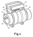
figure 2 . - Figure 4.
- Illustrates a perspective view of the claimed invention.
- In
figure 1 an embodiment of the invention is illustrated as a clearing saw. The power tool comprises a power source 11, normally a combustion engine, and related components, like for example fuel tank, muffler and a starting device placed in one end of atube 12. The tube extends in longitudinal direction of the tool. The length of the tube depends on which type of work the tool is designed for. In the opposite end as the engine a not illustrated working tool is placed. The working tool is selected for the specific work that the tool will be used for. Examples of working tools are hedge trimmer blades, a guide bar with a saw chain, a cutting blade, or a filament cutter. Ahandle bar 14 is attached to thetube 12 somewhere along thetube 12 in order to make it possible for the operator to maneuver thetool 10. Thehandle bar 14 is secured to thetube 12 by aholding device 15. - Tools provided with a
handle bar 14 are supported by a harness or strap extending around the shoulders of the operator. The harness or strap is attached to aloop 13 secured to the tool. - The details of the claimed invention are illustrated in
figure 2 ,3 and4 . Asleeve 16 is fixed around thetube 12. Thetube 12 has a circular cross section and theinside 25 of thesleeve 16 has a similar shape as thetube 12. Thesleeve 16 is clamped to thetube 12 by a twoscrews 17 placed in the ends of thesleeve 16. The outside 18 of thesleeve 16 has a non-circular shape. In the illustrated embodiment the outside 18 of thesleeve 16 is oval but all other non-circular shapes could be used. Alayer 19 covering substantially the entire circumference of the oval section of thesleeve 16 surrounds thesleeve 16. Thelayer 19 has a substantially constant thickness in radial direction around thesleeve 16 and is made of an elastic material. The elastic material will reduce the amount of vibrations transferred from thetool 10 to thehandle bar 14. The thickness of the elastic layer is between 2 and 15 millimeters but to ensure a satisfying reduction of vibrations in thehandle bar 14 theelastic layer 19 should be at least 3 millimeters and made of rubber or a material with similar features. - The
elastic layer 19 is surrounded by acavity 21 formed in a first end 20 of the holdingdevice 15. Thecavity 21 has the same non-circular shape as the outside 18 of thesleeve 16. The non-circular shape of the outside 18 of thesleeve 16 and thecavity 21 in the holdingdevice 15 keeps the holdingdevice 15 in the predetermined position in relation to thesleeve 16 even though thesleeve 16 is surrounded by theelastic layer 19. This feature is essential for the claimed invention. - The thickness of the
elastic layer 19 as well as the shape of the outside 18 of thesleeve 16 and of the cavity may vary in axial direction along thetube 12 to avoid movements in axial direction between thesleeve 16, theelastic layer 19 and the holdingdevice 15. A changed thickness of theelastic layer 19 or a change of the shape of the outside 18 of thesleeve 16 and of the cavity must however be accomplished by a similar change in the close contact layer or surface. - The first end 20 of the holding
device 15 comprises afirst section 22 with one part of thecavity 21 and asecond section 23 with the remaining part of thecavity 21. The twosections device 15 around thesleeve 16 and theelastic layer 19. Thesecond section 23 is fastened to thefirst section 22 integrated in the holdingdevice 15 by fourscrews 24. The cavity could also be divided into more than twosections - At the second end of the holding
device 15, illustrated infigure 1 , the handle bar is secured to the holding device.
Claims (8)
- A portable power tool comprising:- an elongate tube (12),- a power source (11) placed at a first end of the tube (12),- a working tool placed at a second end of the tube (12), and- a handle bar (14) secured to the tube (12) by a holding device (15) placed between the handle bar (14) and the tube (12)characterized in that a sleeve (16) is fixed around the tube (12), the inside (25) of said sleeve (16) is shaped to match the cross section of the tube (12) and the outside (18) of said sleeve has a non-circular shape, said sleeve (16) is at least partially surrounded by a layer (19) of an elastic material, and said holding device (15) is provided with a cavity (21) with a similar shape as the outside (18) of the sleeve (16) and is arranged to be clamped around the sleeve (16) and layer (19) of elastic material.
- A portable power tool according to claim 1, characterized in that the tube (12) and the inside (25) of the sleeve (16) have a circular cross section.
- A portable power tool according to claim 1 or 2, characterized in that the outside (18) of the sleeve (16) and the cavity (21) have an oval shape.
- A portable power tool according to claim 1, 2 or 3, characterized in that the layer (19) of elastic material is extending around substantially the entire sleeve (16).
- A portable power tool according to any of the previous claims, characterized in that the layer (19) of elastic material is made of rubber or a material with similar features.
- A portable power tool according to any of the previous claims, characterized in that the thickness of the layer (19) of elastic material is 2 to 15 millimeter.
- A portable power tool according to claim 6, characterized in that the thickness of layer (19) of elastic material is 3 to 7 millimeters.
- A portable power tool according to any of the previous claims, characterized in that the end (20) of the holding device (15) where the cavity (21) is located comprises at least two sections (22, 23) dividing the cavity (21) into at least two parts to make it possible to clamp the holding device (15) around the sleeve (16).
Priority Applications (1)
| Application Number | Priority Date | Filing Date | Title |
|---|---|---|---|
| PL05754837T PL1761124T3 (en) | 2004-07-01 | 2005-06-29 | Arrangement for securing a handle bar to a portable tool |
Applications Claiming Priority (2)
| Application Number | Priority Date | Filing Date | Title |
|---|---|---|---|
| SE0401706A SE0401706D0 (en) | 2004-07-01 | 2004-07-01 | Arrangement for securing a handle bar to a portable tool |
| PCT/SE2005/001045 WO2006004515A1 (en) | 2004-07-01 | 2005-06-29 | Arrangement for securing a handle bar to a portable tool |
Publications (2)
| Publication Number | Publication Date |
|---|---|
| EP1761124A1 EP1761124A1 (en) | 2007-03-14 |
| EP1761124B1 true EP1761124B1 (en) | 2012-02-22 |
Family
ID=32733731
Family Applications (1)
| Application Number | Title | Priority Date | Filing Date |
|---|---|---|---|
| EP05754837A Expired - Lifetime EP1761124B1 (en) | 2004-07-01 | 2005-06-29 | Arrangement for securing a handle bar to a portable tool |
Country Status (8)
| Country | Link |
|---|---|
| US (1) | US20070214917A1 (en) |
| EP (1) | EP1761124B1 (en) |
| JP (1) | JP2008504815A (en) |
| CN (1) | CN101010000A (en) |
| AT (1) | ATE546039T1 (en) |
| PL (1) | PL1761124T3 (en) |
| SE (1) | SE0401706D0 (en) |
| WO (1) | WO2006004515A1 (en) |
Families Citing this family (3)
| Publication number | Priority date | Publication date | Assignee | Title |
|---|---|---|---|---|
| WO2015094027A1 (en) | 2013-12-16 | 2015-06-25 | Husqvarna Ab | Handle arrangement for a power tool |
| EP3277070B1 (en) * | 2015-04-01 | 2020-01-29 | Techtronic Outdoor Products Technology Limited | Handle with wireless control |
| CN117415095A (en) * | 2023-11-03 | 2024-01-19 | 山东省产品质量检验研究院 | A kind of dirt cleaning device for mechanical calibration and detection |
Family Cites Families (15)
| Publication number | Priority date | Publication date | Assignee | Title |
|---|---|---|---|---|
| US3581832A (en) * | 1968-06-01 | 1971-06-01 | Stihl Maschf Andreas | Free-cutting device |
| JPS501702Y2 (en) * | 1971-09-28 | 1975-01-17 | ||
| DE2743043C2 (en) * | 1977-09-24 | 1987-05-14 | Fa. Andreas Stihl, 7050 Waiblingen | Vibration-damping connection between a vibration-exposed device part and a handle-side device part for a portable work tool |
| JPS5942530Y2 (en) * | 1980-02-15 | 1984-12-12 | 小松ゼノア株式会社 | Vibration isolator |
| JPH046508Y2 (en) * | 1987-05-19 | 1992-02-21 | ||
| US4819742A (en) * | 1987-06-12 | 1989-04-11 | White Consolidated Industries, Inc. | Vibration-damping control handle for a portable power tool |
| JPH09303354A (en) * | 1996-05-21 | 1997-11-25 | Kioritz Corp | A retaining structure and a brush cutter provided with the retaining structure |
| DE19843157B4 (en) * | 1997-09-22 | 2009-01-22 | Kioritz Corp. | Engine machine with safety mechanism |
| DE10132951B4 (en) * | 2000-07-15 | 2006-04-20 | Andreas Stihl Ag & Co | Hand-held implement |
| JP2002168288A (en) * | 2000-09-20 | 2002-06-14 | Toyo Tire & Rubber Co Ltd | Anti-vibration device |
| JP4341805B2 (en) * | 2001-01-24 | 2009-10-14 | 本田技研工業株式会社 | Brush holder handle holder structure |
| JP4537594B2 (en) * | 2001-02-07 | 2010-09-01 | 本田技研工業株式会社 | Brush cutter |
| US6540216B2 (en) * | 2001-05-23 | 2003-04-01 | Freudenberg-Nok General Partnership | Foamed elastomer engine mount isolating bushing |
| US7052002B2 (en) * | 2004-02-12 | 2006-05-30 | Tokai Rubber Industries, Ltd. | Vibration-damping device |
| GB0409595D0 (en) * | 2004-04-29 | 2004-06-02 | Avon Vibration Man Syst Ltd | Bush assembly |
-
2004
- 2004-07-01 SE SE0401706A patent/SE0401706D0/en unknown
-
2005
- 2005-06-29 PL PL05754837T patent/PL1761124T3/en unknown
- 2005-06-29 WO PCT/SE2005/001045 patent/WO2006004515A1/en not_active Ceased
- 2005-06-29 JP JP2007519167A patent/JP2008504815A/en active Pending
- 2005-06-29 US US11/570,056 patent/US20070214917A1/en not_active Abandoned
- 2005-06-29 AT AT05754837T patent/ATE546039T1/en active
- 2005-06-29 CN CNA200580021753XA patent/CN101010000A/en active Pending
- 2005-06-29 EP EP05754837A patent/EP1761124B1/en not_active Expired - Lifetime
Also Published As
| Publication number | Publication date |
|---|---|
| US20070214917A1 (en) | 2007-09-20 |
| WO2006004515A1 (en) | 2006-01-12 |
| ATE546039T1 (en) | 2012-03-15 |
| JP2008504815A (en) | 2008-02-21 |
| SE0401706D0 (en) | 2004-07-01 |
| CN101010000A (en) | 2007-08-01 |
| EP1761124A1 (en) | 2007-03-14 |
| PL1761124T3 (en) | 2012-09-28 |
Similar Documents
| Publication | Publication Date | Title |
|---|---|---|
| EP4065323B1 (en) | Powered handheld cutting tool | |
| EP0284659A2 (en) | Vibration-damping control handle for a portable power tool | |
| US8499674B2 (en) | Yoke accessory tool for an oscillating tool | |
| CA1297916C (en) | Vibration-damping control handle for a portable power tool | |
| CN103118529B (en) | For the door handle device of power tool | |
| US10334779B2 (en) | Balanced trim shield with a single, dual direction line cutting member | |
| WO2003028966A3 (en) | Power tools and blades for use with power tools | |
| WO2013077862A1 (en) | Yoke accessory tool for an oscillating tool | |
| US20070214917A1 (en) | Arrangement for Securing a Handlebar to a Portable Tool | |
| JP2001224215A (en) | Working machine equipped with driving engine | |
| KR100648485B1 (en) | Bush cutting machine | |
| EP1530890A1 (en) | Portable device with anti-vibration handle for use in agriculture and gardening | |
| WO2007069551A1 (en) | Bending attachment and portable mowing machine mounted with this | |
| US20230339089A1 (en) | Handle for use with power tool | |
| JP2002300814A (en) | Handle mounting device | |
| CA2308656A1 (en) | Saw for cutting hard materials | |
| EP1962574B1 (en) | Handle with reduced vibrations | |
| US20220126476A1 (en) | Power Tool with a Dust Collection Attachment | |
| JP4097248B2 (en) | Takaeda mower | |
| EP1986486A1 (en) | A portable tool comprising an engine placed at one end of an elongated tube and a working tool placed in the opposite end. | |
| JP2012213914A (en) | Guide bar of chain saw and chain saw | |
| JP2026013803A (en) | Work equipment | |
| US4991296A (en) | Hedge trimmer | |
| EP1508267B1 (en) | Device for cutting vegetation or for other applications, with electric motor and reducing gear | |
| EP3274142A1 (en) | Cutting device with pivoting working assembly |
Legal Events
| Date | Code | Title | Description |
|---|---|---|---|
| PUAI | Public reference made under article 153(3) epc to a published international application that has entered the european phase |
Free format text: ORIGINAL CODE: 0009012 |
|
| 17P | Request for examination filed |
Effective date: 20061206 |
|
| AK | Designated contracting states |
Kind code of ref document: A1 Designated state(s): AT BE BG CH CY CZ DE DK EE ES FI FR GB GR HU IE IS IT LI LT LU MC NL PL PT RO SE SI SK TR |
|
| RAP1 | Party data changed (applicant data changed or rights of an application transferred) |
Owner name: HUSQVARNA AB |
|
| DAX | Request for extension of the european patent (deleted) | ||
| 17Q | First examination report despatched |
Effective date: 20100830 |
|
| GRAP | Despatch of communication of intention to grant a patent |
Free format text: ORIGINAL CODE: EPIDOSNIGR1 |
|
| RIN1 | Information on inventor provided before grant (corrected) |
Inventor name: EJDEHAG, FREDRIK |
|
| GRAS | Grant fee paid |
Free format text: ORIGINAL CODE: EPIDOSNIGR3 |
|
| GRAA | (expected) grant |
Free format text: ORIGINAL CODE: 0009210 |
|
| AK | Designated contracting states |
Kind code of ref document: B1 Designated state(s): AT BE BG CH CY CZ DE DK EE ES FI FR GB GR HU IE IS IT LI LT LU MC NL PL PT RO SE SI SK TR |
|
| REG | Reference to a national code |
Ref country code: GB Ref legal event code: FG4D |
|
| REG | Reference to a national code |
Ref country code: CH Ref legal event code: EP |
|
| REG | Reference to a national code |
Ref country code: AT Ref legal event code: REF Ref document number: 546039 Country of ref document: AT Kind code of ref document: T Effective date: 20120315 |
|
| REG | Reference to a national code |
Ref country code: IE Ref legal event code: FG4D |
|
| REG | Reference to a national code |
Ref country code: DE Ref legal event code: R096 Ref document number: 602005032801 Country of ref document: DE Effective date: 20120419 |
|
| REG | Reference to a national code |
Ref country code: SE Ref legal event code: TRGR |
|
| REG | Reference to a national code |
Ref country code: NL Ref legal event code: VDEP Effective date: 20120222 |
|
| LTIE | Lt: invalidation of european patent or patent extension |
Effective date: 20120222 |
|
| PG25 | Lapsed in a contracting state [announced via postgrant information from national office to epo] |
Ref country code: IS Free format text: LAPSE BECAUSE OF FAILURE TO SUBMIT A TRANSLATION OF THE DESCRIPTION OR TO PAY THE FEE WITHIN THE PRESCRIBED TIME-LIMIT Effective date: 20120622 Ref country code: NL Free format text: LAPSE BECAUSE OF FAILURE TO SUBMIT A TRANSLATION OF THE DESCRIPTION OR TO PAY THE FEE WITHIN THE PRESCRIBED TIME-LIMIT Effective date: 20120222 Ref country code: LT Free format text: LAPSE BECAUSE OF FAILURE TO SUBMIT A TRANSLATION OF THE DESCRIPTION OR TO PAY THE FEE WITHIN THE PRESCRIBED TIME-LIMIT Effective date: 20120222 |
|
| PG25 | Lapsed in a contracting state [announced via postgrant information from national office to epo] |
Ref country code: GR Free format text: LAPSE BECAUSE OF FAILURE TO SUBMIT A TRANSLATION OF THE DESCRIPTION OR TO PAY THE FEE WITHIN THE PRESCRIBED TIME-LIMIT Effective date: 20120523 Ref country code: BE Free format text: LAPSE BECAUSE OF FAILURE TO SUBMIT A TRANSLATION OF THE DESCRIPTION OR TO PAY THE FEE WITHIN THE PRESCRIBED TIME-LIMIT Effective date: 20120222 Ref country code: PT Free format text: LAPSE BECAUSE OF FAILURE TO SUBMIT A TRANSLATION OF THE DESCRIPTION OR TO PAY THE FEE WITHIN THE PRESCRIBED TIME-LIMIT Effective date: 20120622 Ref country code: FI Free format text: LAPSE BECAUSE OF FAILURE TO SUBMIT A TRANSLATION OF THE DESCRIPTION OR TO PAY THE FEE WITHIN THE PRESCRIBED TIME-LIMIT Effective date: 20120222 |
|
| REG | Reference to a national code |
Ref country code: AT Ref legal event code: MK05 Ref document number: 546039 Country of ref document: AT Kind code of ref document: T Effective date: 20120222 |
|
| PG25 | Lapsed in a contracting state [announced via postgrant information from national office to epo] |
Ref country code: CY Free format text: LAPSE BECAUSE OF FAILURE TO SUBMIT A TRANSLATION OF THE DESCRIPTION OR TO PAY THE FEE WITHIN THE PRESCRIBED TIME-LIMIT Effective date: 20120222 |
|
| REG | Reference to a national code |
Ref country code: PL Ref legal event code: T3 |
|
| PG25 | Lapsed in a contracting state [announced via postgrant information from national office to epo] |
Ref country code: CZ Free format text: LAPSE BECAUSE OF FAILURE TO SUBMIT A TRANSLATION OF THE DESCRIPTION OR TO PAY THE FEE WITHIN THE PRESCRIBED TIME-LIMIT Effective date: 20120222 Ref country code: SI Free format text: LAPSE BECAUSE OF FAILURE TO SUBMIT A TRANSLATION OF THE DESCRIPTION OR TO PAY THE FEE WITHIN THE PRESCRIBED TIME-LIMIT Effective date: 20120222 Ref country code: EE Free format text: LAPSE BECAUSE OF FAILURE TO SUBMIT A TRANSLATION OF THE DESCRIPTION OR TO PAY THE FEE WITHIN THE PRESCRIBED TIME-LIMIT Effective date: 20120222 Ref country code: RO Free format text: LAPSE BECAUSE OF FAILURE TO SUBMIT A TRANSLATION OF THE DESCRIPTION OR TO PAY THE FEE WITHIN THE PRESCRIBED TIME-LIMIT Effective date: 20120222 Ref country code: DK Free format text: LAPSE BECAUSE OF FAILURE TO SUBMIT A TRANSLATION OF THE DESCRIPTION OR TO PAY THE FEE WITHIN THE PRESCRIBED TIME-LIMIT Effective date: 20120222 |
|
| PG25 | Lapsed in a contracting state [announced via postgrant information from national office to epo] |
Ref country code: IT Free format text: LAPSE BECAUSE OF FAILURE TO SUBMIT A TRANSLATION OF THE DESCRIPTION OR TO PAY THE FEE WITHIN THE PRESCRIBED TIME-LIMIT Effective date: 20120222 Ref country code: SK Free format text: LAPSE BECAUSE OF FAILURE TO SUBMIT A TRANSLATION OF THE DESCRIPTION OR TO PAY THE FEE WITHIN THE PRESCRIBED TIME-LIMIT Effective date: 20120222 |
|
| PLBE | No opposition filed within time limit |
Free format text: ORIGINAL CODE: 0009261 |
|
| STAA | Information on the status of an ep patent application or granted ep patent |
Free format text: STATUS: NO OPPOSITION FILED WITHIN TIME LIMIT |
|
| 26N | No opposition filed |
Effective date: 20121123 |
|
| PG25 | Lapsed in a contracting state [announced via postgrant information from national office to epo] |
Ref country code: MC Free format text: LAPSE BECAUSE OF NON-PAYMENT OF DUE FEES Effective date: 20120630 Ref country code: AT Free format text: LAPSE BECAUSE OF FAILURE TO SUBMIT A TRANSLATION OF THE DESCRIPTION OR TO PAY THE FEE WITHIN THE PRESCRIBED TIME-LIMIT Effective date: 20120222 |
|
| REG | Reference to a national code |
Ref country code: CH Ref legal event code: PL |
|
| REG | Reference to a national code |
Ref country code: CH Ref legal event code: PL |
|
| REG | Reference to a national code |
Ref country code: DE Ref legal event code: R097 Ref document number: 602005032801 Country of ref document: DE Effective date: 20121123 |
|
| REG | Reference to a national code |
Ref country code: IE Ref legal event code: MM4A |
|
| PG25 | Lapsed in a contracting state [announced via postgrant information from national office to epo] |
Ref country code: LI Free format text: LAPSE BECAUSE OF NON-PAYMENT OF DUE FEES Effective date: 20120630 Ref country code: IE Free format text: LAPSE BECAUSE OF NON-PAYMENT OF DUE FEES Effective date: 20120629 Ref country code: ES Free format text: LAPSE BECAUSE OF FAILURE TO SUBMIT A TRANSLATION OF THE DESCRIPTION OR TO PAY THE FEE WITHIN THE PRESCRIBED TIME-LIMIT Effective date: 20120602 Ref country code: CH Free format text: LAPSE BECAUSE OF NON-PAYMENT OF DUE FEES Effective date: 20120630 |
|
| PG25 | Lapsed in a contracting state [announced via postgrant information from national office to epo] |
Ref country code: BG Free format text: LAPSE BECAUSE OF FAILURE TO SUBMIT A TRANSLATION OF THE DESCRIPTION OR TO PAY THE FEE WITHIN THE PRESCRIBED TIME-LIMIT Effective date: 20120522 |
|
| PG25 | Lapsed in a contracting state [announced via postgrant information from national office to epo] |
Ref country code: TR Free format text: LAPSE BECAUSE OF FAILURE TO SUBMIT A TRANSLATION OF THE DESCRIPTION OR TO PAY THE FEE WITHIN THE PRESCRIBED TIME-LIMIT Effective date: 20120222 |
|
| PG25 | Lapsed in a contracting state [announced via postgrant information from national office to epo] |
Ref country code: LU Free format text: LAPSE BECAUSE OF NON-PAYMENT OF DUE FEES Effective date: 20120629 |
|
| PG25 | Lapsed in a contracting state [announced via postgrant information from national office to epo] |
Ref country code: HU Free format text: LAPSE BECAUSE OF FAILURE TO SUBMIT A TRANSLATION OF THE DESCRIPTION OR TO PAY THE FEE WITHIN THE PRESCRIBED TIME-LIMIT Effective date: 20050629 |
|
| REG | Reference to a national code |
Ref country code: FR Ref legal event code: PLFP Year of fee payment: 12 |
|
| REG | Reference to a national code |
Ref country code: FR Ref legal event code: PLFP Year of fee payment: 13 |
|
| REG | Reference to a national code |
Ref country code: FR Ref legal event code: PLFP Year of fee payment: 14 |
|
| PGFP | Annual fee paid to national office [announced via postgrant information from national office to epo] |
Ref country code: DE Payment date: 20180524 Year of fee payment: 14 |
|
| PGFP | Annual fee paid to national office [announced via postgrant information from national office to epo] |
Ref country code: GB Payment date: 20180523 Year of fee payment: 14 |
|
| REG | Reference to a national code |
Ref country code: DE Ref legal event code: R119 Ref document number: 602005032801 Country of ref document: DE |
|
| GBPC | Gb: european patent ceased through non-payment of renewal fee |
Effective date: 20190629 |
|
| PG25 | Lapsed in a contracting state [announced via postgrant information from national office to epo] |
Ref country code: DE Free format text: LAPSE BECAUSE OF NON-PAYMENT OF DUE FEES Effective date: 20200101 Ref country code: GB Free format text: LAPSE BECAUSE OF NON-PAYMENT OF DUE FEES Effective date: 20190629 |
|
| PGFP | Annual fee paid to national office [announced via postgrant information from national office to epo] |
Ref country code: SE Payment date: 20220513 Year of fee payment: 18 |
|
| PGFP | Annual fee paid to national office [announced via postgrant information from national office to epo] |
Ref country code: PL Payment date: 20220412 Year of fee payment: 18 |
|
| P01 | Opt-out of the competence of the unified patent court (upc) registered |
Effective date: 20230419 |
|
| PGFP | Annual fee paid to national office [announced via postgrant information from national office to epo] |
Ref country code: FR Payment date: 20230522 Year of fee payment: 19 |
|
| REG | Reference to a national code |
Ref country code: SE Ref legal event code: EUG |
|
| PG25 | Lapsed in a contracting state [announced via postgrant information from national office to epo] |
Ref country code: SE Free format text: LAPSE BECAUSE OF NON-PAYMENT OF DUE FEES Effective date: 20230630 |
|
| PG25 | Lapsed in a contracting state [announced via postgrant information from national office to epo] |
Ref country code: PL Free format text: LAPSE BECAUSE OF NON-PAYMENT OF DUE FEES Effective date: 20230629 |
|
| PG25 | Lapsed in a contracting state [announced via postgrant information from national office to epo] |
Ref country code: PL Free format text: LAPSE BECAUSE OF NON-PAYMENT OF DUE FEES Effective date: 20230629 |
|
| PG25 | Lapsed in a contracting state [announced via postgrant information from national office to epo] |
Ref country code: FR Free format text: LAPSE BECAUSE OF NON-PAYMENT OF DUE FEES Effective date: 20240630 |