EP1760883B1 - Element einer Energiespeichervorrichtung und zugehöriger Generator - Google Patents
Element einer Energiespeichervorrichtung und zugehöriger Generator Download PDFInfo
- Publication number
- EP1760883B1 EP1760883B1 EP20060291369 EP06291369A EP1760883B1 EP 1760883 B1 EP1760883 B1 EP 1760883B1 EP 20060291369 EP20060291369 EP 20060291369 EP 06291369 A EP06291369 A EP 06291369A EP 1760883 B1 EP1760883 B1 EP 1760883B1
- Authority
- EP
- European Patent Office
- Prior art keywords
- capacitors
- element according
- generator
- truncated
- capacitor
- Prior art date
- Legal status (The legal status is an assumption and is not a legal conclusion. Google has not performed a legal analysis and makes no representation as to the accuracy of the status listed.)
- Expired - Fee Related
Links
Images


Classifications
-
- H—ELECTRICITY
- H03—ELECTRONIC CIRCUITRY
- H03K—PULSE TECHNIQUE
- H03K3/00—Circuits for generating electric pulses; Monostable, bistable or multistable circuits
- H03K3/02—Generators characterised by the type of circuit or by the means used for producing pulses
- H03K3/53—Generators characterised by the type of circuit or by the means used for producing pulses by the use of an energy-accumulating element discharged through the load by a switching device controlled by an external signal and not incorporating positive feedback
- H03K3/537—Generators characterised by the type of circuit or by the means used for producing pulses by the use of an energy-accumulating element discharged through the load by a switching device controlled by an external signal and not incorporating positive feedback the switching device being a spark gap
Definitions
- the present invention relates to the field of capacitors, in particular with a view to their application in a high-voltage generator of pulses, of the MARX type comprising a large number of electrically connected capacitors in parallel, series connected load resistances and spark gaps, of such so that the input voltage charges in parallel the capacitors and that these are discharged in series via the spark gaps.
- the figure 1 represents the wiring diagram of a MARX type generator.
- C T denotes capacitors, R load resistors and E spark gaps each having two half-spark gaps.
- the capacitors C T charged in parallel with the input voltage V1, are put in series by means of spark gaps E.
- n is the number of stages or the number of capacitors C T
- C T the capacity of a capacitor (or a stage)
- the equivalent capacitance of the entire generator of MARX is equal to C / n.
- the capacitors C T are discharged in series via the spark gaps E.
- the trigger pulse is applied to an auxiliary electrode only present on the first spark gap.
- the voltages at the terminals of each capacitor C T are put in series, so they add up.
- FR2823033 discloses a high voltage pulse generator of the MARX type comprising a large number of electrically connected capacitors in parallel, series connected load resistors and spark gaps, so that the input voltage charges in parallel the capacitors and that these are discharged in series via the gaps.
- This generator is constituted by a cylindrical compact block comprising slabs superposed, each slab, also called stage, comprising several capacitors electrically connected with load resistors and with two half-spark gaps, the assembly being embedded in an insulating coating resin.
- each wafer comprises at least one series of capacitors juxtaposed so as to form a ring, each capacitor forming a sector of said ring, the capacitors being connected on each side to a conductive plate or to high voltage printed circuits.
- Each of the two half-gaps of the same stage form a spark gap with a half spark gap of the adjacent downstream stage for one, and with a half spark gap of the upstream adjacent stage for the other.
- This slab concept makes it possible to produce a modular Marx generator whose maximum output voltage is defined by the number of stages, and therefore superposed slabs.
- the specific design of these stages is such that the spark gaps are arranged in a central channel containing a gas under pressure and allowing their simultaneous release. This avalanche phenomenon is improved by photoelectric effect related to the strong production of ultraviolet radiation at the time of the electric discharge at the level of the spark gaps.
- the energy stored in such a generator depends on the one hand on the physical characteristics of the capacitors and on the number of stages of the generator and, on the other hand, on the charge voltage applied to each of the stages. But increasing the size of the capacitors or the number of stages increases the size of the generator while the increase of the charging voltage causes a surface breakdown phenomenon by bypassing short circuit the corresponding stage.
- the object of the invention is to solve these problems by proposing a high-voltage generator of pulses for storing more energy than existing generators and having no risk of surface breakdown by bypass.
- a generator according to the patent application FR2823033 also has the disadvantage of not being able to be achieved when there is no coating installation.
- the object of the invention is also to solve this drawback by proposing elements of an energy storage device that does not possibly require coating during the manufacture of the generator.
- the solution provided is an element of an energy storage device comprising at least one capacitor coated, individually or not, with a coating and characterized in that the coating has an outer form of truncated sector.
- the element comprises at least one capacitor having a truncated sector shape.
- At least one groove or channel is formed in the coating, this groove or channel preferably having two ends which open on the same face of the assembly, in this case on the truncated face of the sector formed by said set.
- such an element can be used in a generator comprising superposed wafers G 1 , G 2 , G 3 , G 4 ... G i ..., each comprising at least one capacitor C connected to a load resistor R and with two half-spark gaps (e 1i , e 2i ,), the generator thus having spark gaps (E) formed by two half-spark gaps (e 1i + 1 and e 2i ,), one of which is connected to said at least one capacitor C belonging to the wafer G i and the other said at least one capacitor C belonging to the wafer G i + 1 , characterized in that a solid (20) is disposed between at least two half-gaps (e 1i +1 , e 2i ) of a spark gap (E), the ends that open out of said groove must be on either side of the solid).
- said channel or said groove has a shape of U.
- the truncated face of the sector formed by said assembly comprises a groove or lips.
- the element comprises fastening elements arranged projecting or withdrawn from the external surface of the coating and fixed or not fixed to a flexible sheet, a foil or printed circuit or a conductive plate, these elements of fixation that can include a obviously.
- a high-voltage generator of pulses of the MARX type generally comprises a large number of capacitors C T connected electrically in parallel, load resistances R connected in series and spark gaps E, so that the input voltage charges in parallel capacitors C T and that they are discharged in series via spark gaps E.
- Each spark gap E has two half-spark gaps.
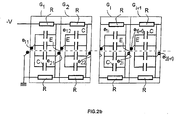
- a pancake generator is constituted, as shown on the figure 2a , by a cylindrical compact block comprising superposed slabs G 1 , G 2 , G 3 , G 4 ..., also called stages.
- Each galette G i comprises, as presented on the figures 2b and 3 , several capacitors C in parallel connected to load resistors R and two half-gaps e 1i and e 2i , these capacitors being juxtaposed to form a crown 5.
- the assembly is embedded in an insulating coating resin 4.
- the index i of the half-spark gaps corresponds to the index of the corresponding stage. For the sake of clarity, only four floors were represented on the electrical diagram of the figure 2b .
- the capacitor C T of the figure 1 corresponds to all the capacitors C present in a stage.
- each spark gap is composed of two half-spark gaps e 1i + 1 and e 2i , one of which belongs to the floor G i and the other to the floor G i + 1 .
- Each capacitor C forms a sector of this ring 5.
- the current dimensions of the sector are related to technological constraints of industrial production of capacitors.
- the capacitors C are electrically connected on each side, by conductive fixing elements 19, to a conductive plate 6 of circular shape arranged coaxially with said ring gear 5.
- This ring 5 comprises two diametrically opposed parts 7, unoccupied by a capacitor, each forming a housing for a load resistor R electrically connected to the circular plate 6.
- the circular plate 6 carries on its inner periphery a conductive blade 8 projecting into a central circular recess 9 of the slab.
- the ends of these blades 8 each carry a half spark gap, respectively e 1i and e 2i .
- the blades 8 are connected to the circular plate 6 in the zone 7 unoccupied by a capacitor.
- the two half-gaps e 1i and e 2i are arranged in the circular recess 9 and are located in two axially offset planes P1 and P2, one of the half-gaps being located above the other.
- a solid 20 is disposed between the two half-spark spheres e 1i and e 2i and separate the circular recess in two parts respectively 9 1 and 9 2 .
- This solid 20 is able to electrically isolate the two half-gaps e 1i and e 2i of the stage G i . It consists of a plate made of material having a transmittance, preferably greater than 80% in the ultraviolet and especially in the frequency band between 250 and 400 nm. In this embodiment of the invention, this solid is constituted by a glass plate 20 anchored on each side in a groove 22 formed in the coating 4 of each of the patties.
- two diametrically opposed channels 21a and 21b presented on the figure 4 and whose length is greater than that separating the two half-gaps e 1i and e 2i , connect said portions 9 1 and 9 2 of the circular recess 9.
- the superimposed wafers G 1 , G 2 , G 3 ... are electrically connected to each other by two diametrically opposed metal rods 11 passing through the conductive plates 6 in the zone 7 unoccupied by a capacitor.
- the series of capacitors C disposed along the ring 5 is surrounded at least by a second series of capacitors C1 forming a second ring 12.
- the capacitors of this second series are electrically connected by a circular conductive plate concentric to that which connects the capacitors C of the first series. They make it possible to considerably increase the energy stored per elementary stage.
- each stage is coated with a resin coating 22 which comprises a circular channel 21a and 21b each bypassing a capacitor C.
- Their length is sufficient to avoid a breakdown between the two half-gaps e 1i and e 2i and via said channel 21 and taking into account the charging voltage and the gas pressure in the recess 9. It is recalled that these two characteristics are related by the law of Paschen which fixes the distance of the half-gaps e 1i and e 2i and the nature of the gas in which they bathe for a given disruptive tension.
- each capacitor C, C1 comprises one or more ceramic plates 13 whose opposite faces are in contact with conductive pads 14 in contact with a conductive plate 6.
- each capacitor comprises two ceramic plates 13, whereas in the case of the figure 6 each capacitor comprises three ceramic plates 13.
- the slab 1A has a greater thickness than the slab 1 of the figure 5 .
- the coating resin 4 may be epoxy resin.
- the superimposed slabs 1,2, 3 are contained inside a cylindrical outer envelope 15, as shown in FIG. figure 2 .
- this envelope is made of metal.
- This outer casing 15 may also contain at its lower part a DC-DC converter 16 and batteries 17 to make the generator MARX autonomous.
- such a generator in its autonomous version, allows to consider applications with very high pulsed energy while maintaining the absence of dangerous electrical connections with high-voltage sources (this one is integrated), which improves comfort and safety of use. It is possible to envisage remote control for the synchronized triggering or not of one or more generators of this concept.
- This new design makes it possible to produce generators with a lower rise time (very low parasitic self) which are particularly useful for controlling a microwave tube for producing microwave radiation or driving an antenna directly, via the shaping line of the antenna. pulse, to achieve ultra-wide band or broadband radiation.
- first truncated pre-coated sectors 30 and 31 each comprising one or more capacitors C and two second truncated sectors 32 each comprising a resistor charge connected to a half-gap e 1i or e 2i disposed beyond the truncated portion 34 of the sector 32.
- These sectors 30 and 32 are truncated so as to form a ring having a central recess 9.
- the central recess is circular in shape.
- the truncated sectors 30, forming with the second truncated sectors 32 a first inner ring 35 do not have the same dimensions as the truncated sectors 31 forming an outer ring 36, the first and second rings being concentric. Indeed, the angle of the first sectors 31 of the inner ring 35 is equal, in this embodiment, to the angle formed by two juxtaposed sectors of the outer ring 36.
- the Figures 8a, 8b and 8c show several embodiments of the first truncated sectors 30 of the inner ring 35, these truncated sectors forming elements of the energy storage device constituted by the generator.
- These sectors which may comprise one or more capacitors, may either have the simple shape of a truncated sector as shown in FIG. figure 8a , that is, to have some adjustments.
- the truncated sector 30b has in addition, compared to that of the figure 8a , a channel 21a formed in the coating 4 whose function, in the context of the generator according to the invention, is to ensure an equipression on both sides of the solid 20.
- the channel 21a is replaced by a groove 25 formed in the coating 4 opening on the truncated face 24 of the sector and formed on three consecutive faces of the sector or on only one of its faces.
- FIGS. 8e and 8f have sectors similar to those of respective figures 8a and 8b, but having, in addition, a groove 22 on their truncated face 24.
- This groove 22 is intended to allow the anchoring of a portion of the periphery of a solid 20 .
- the inner ring 35 has six sectors 30e according to the figure 8e and 2 sectors 30f according to the figure 8f , diametrically opposed.
- connection is as described in the exemplary embodiment of the Figures 2 to 6 .
- a global coating of a crown or a stage can be made in order to minimize the risk of bypassing breakdown compared with a simple juxtaposition of sectors.
- connection elements 50 to weld on both sides of the coating 51.
- One of these elements may, for example, be connected to a plate as in the embodiment of Figures 2 to 6 or, for example, a foil or a printed circuit 52.
- these connection elements 50 may include a recess 53 to avoid possible problems of thermal inertia.
- the generator may comprise capacitors of different shapes and not comprise a circular slab but of another shape.
- the solid stored between the two gaps may have any shape, provided that it increases the minimum value of the voltage from which appears the breakdown phenomenon. Fixing this solid between the two electrodes of the spark gap can be done by any appropriate means, these means may be integral with the solid, the elements of the energy storage device or part of both. It can also be fixed by simply pressing the elements of the accumulation device of energy on the solid.
- the spark gaps can take any suitable shape having at least two electrodes.
Claims (11)
- Element (30, 30a, 30b, 30c, 30d, 30e, 30f, 31) einer Energiespeichervorrichtung mit mindestens einem Kondensator (C), auf den eine Beschichtung (4) einzeln oder nicht einzeln aufgebracht wird, dadurch gekennzeichnet, dass die Außenform dieser Beschichtung (4) aus einem stumpfförmigen Segment besteht.
- Element nach Anspruch 1, dadurch gekennzeichnet, dass dieses Element mindestens einen Kondensator (C) in Form eines stumpfförmigen Segmentes besitzt.
- Element nach einem beliebigen der vorhergehenden Ansprüche 1 oder 2, dadurch gekennzeichnet, dass mindestens eine Rille (25) oder ein Kanal (21a, 21b) in die Beschichtung (4) eingebracht wird.
- Element nach Anspruch 3, dadurch gekennzeichnet, dass die Rille (25) oder der Kanal (21a, 21b) zwei Enden besitzt, die zu derselben Fläche (24) der Beschichtung führen.
- Element nach Anspruch 4, dadurch gekennzeichnet, dass beide Enden der Rille (25) oder des Kanals (21a, 21b) zur abgestumpften Fläche (24) des stumpfförmigen Segmentes führen.
- Element nach einem beliebigen der vorhergehenden Ansprüche 3 bis 5, dadurch gekennzeichnet, dass der Kanal (21a, 21 b) oder die Rille (25) U-förmig ist.
- Element nach einem beliebigen der vorhergehenden Ansprüche 1 bis 6, dadurch gekennzeichnet, dass die abgestumpfte Fläche (24) des stumpfförmigen Segmentes eine Nut (22) oder Lippen aufweist.
- Element nach einem beliebigen der vorhergehenden Ansprüche 1 bis 7, dadurch gekennzeichnet, dass sich Befestigungs- und/oder Stromanschlusselemente (50, 19) nach vorne oder nach hinten versetzt in der Außenfläche der Beschichtung (4) befinden.
- Element nach Anspruch 8, dadurch gekennzeichnet, dass eines der Befestigungsund/oder Stromanschlusselemente (50, 19) an einer elastischen Isolierplatte, einer Metallfolie oder einer gedruckten Schaltung befestigt ist.
- Element nach einem beliebigen der vorhergehenden Ansprüche 1 bis 7, dadurch gekennzeichnet, dass mindestens eines der Befestigungs- und/oder Stromanschlusselemente (50, 19) nach vorne versetzt angeordnet ist und eine Aussparung (53) aufweist.
- Spannungsgenerator, der ein Element nach einem beliebigen der vorhergehenden Ansprüche 1 bis 10 besitzt.
Applications Claiming Priority (1)
| Application Number | Priority Date | Filing Date | Title |
|---|---|---|---|
| FR0508839A FR2890228B1 (fr) | 2005-08-30 | 2005-08-30 | Element d'un dispositif d'accumulation d'energie et generateur associe. |
Publications (2)
| Publication Number | Publication Date |
|---|---|
| EP1760883A1 EP1760883A1 (de) | 2007-03-07 |
| EP1760883B1 true EP1760883B1 (de) | 2010-05-05 |
Family
ID=36216952
Family Applications (1)
| Application Number | Title | Priority Date | Filing Date |
|---|---|---|---|
| EP20060291369 Expired - Fee Related EP1760883B1 (de) | 2005-08-30 | 2006-08-29 | Element einer Energiespeichervorrichtung und zugehöriger Generator |
Country Status (3)
| Country | Link |
|---|---|
| EP (1) | EP1760883B1 (de) |
| DE (1) | DE602006014070D1 (de) |
| FR (1) | FR2890228B1 (de) |
Family Cites Families (4)
| Publication number | Priority date | Publication date | Assignee | Title |
|---|---|---|---|---|
| FR2098513A5 (de) * | 1970-07-09 | 1972-03-10 | Commissariat Energie Atomique | |
| FR2569319B1 (fr) * | 1984-08-14 | 1986-11-14 | Commissariat Energie Atomique | Generateur d'impulsions |
| FR2622044B1 (de) * | 1987-10-19 | 1990-03-02 | Aerospatiale | |
| FR2823033B1 (fr) * | 2001-03-28 | 2003-06-13 | I S L Inst Franco Allemand De | Generateur haute tension d'impulsions de type marx |
-
2005
- 2005-08-30 FR FR0508839A patent/FR2890228B1/fr not_active Expired - Fee Related
-
2006
- 2006-08-29 DE DE200660014070 patent/DE602006014070D1/de active Active
- 2006-08-29 EP EP20060291369 patent/EP1760883B1/de not_active Expired - Fee Related
Also Published As
| Publication number | Publication date |
|---|---|
| DE602006014070D1 (de) | 2010-06-17 |
| FR2890228B1 (fr) | 2007-10-19 |
| EP1760883A1 (de) | 2007-03-07 |
| FR2890228A1 (fr) | 2007-03-02 |
Similar Documents
| Publication | Publication Date | Title |
|---|---|---|
| EP0162766B1 (de) | Hochenergie- und Hochspannungsspeichervorrichtung und Verwendung als Impulsgenerator | |
| EP0086136B1 (de) | Generator elektromagnetischer Hochspannungsimpulse | |
| FR2569319A1 (fr) | Generateur d'impulsions | |
| EP0308662B1 (de) | Zahnsteinentferner | |
| EP1760884B1 (de) | Hochspannungsimpulsgenerator | |
| EP1760883B1 (de) | Element einer Energiespeichervorrichtung und zugehöriger Generator | |
| EP0058389B1 (de) | Gas-Laser, angeregt durch Entladung von Kondensatoren | |
| EP3884526B1 (de) | Flexibler satellitensolargenerator und dessen herstellungsverfahren | |
| EP3272010A1 (de) | Hochspannungsimpulsgenerator | |
| EP0313439B1 (de) | Bauelement zum Speichern von elektrischer Energie bei sehr hoher Spannung | |
| FR2702900A1 (fr) | Générateur de Marx. | |
| FR2823033A1 (fr) | Generateur haute tension d'impulsions de type marx | |
| WO1980001439A1 (en) | Electrically energized gaseous active medium pulse laser | |
| FR2987288A1 (fr) | Tete d'un dispositif de decharge electrohydraulique par fil explose | |
| EP0048425B1 (de) | Gas-Laser | |
| EP2660977B1 (de) | Stufe für Spannungsgenerator, und entsprechender Spannungsgenerator | |
| EP3316350A1 (de) | Elektrisches anschlussstück für akkumulator | |
| EP0119927B1 (de) | Hochspannungsverstärker für kapazitive Last | |
| FR2734395A3 (fr) | Film dielectrique metallise, et condensateur auto-cicatrisant realise a partir d'un tel film | |
| EP0084340A2 (de) | Gaslaser angeregt mittels Entladungskapazität | |
| EP0313440B1 (de) | Gehäuse für eine Vorrichtung zum Speichern von elektrischer Energie bei sehr hoher Spannung und eine solche Vorrichtung | |
| EP3852945A1 (de) | Anordnung zum verformen von metallteilen mittels magnetischer impulse | |
| FR2489050A1 (fr) | Laser a gaz excite par decharge de condensateurs | |
| FR2597983A1 (fr) | Miroir a surface modulable pour systeme optique adaptateur de front d'onde | |
| FR2920257A1 (fr) | Laser a excitation optique et son milieu actif |
Legal Events
| Date | Code | Title | Description |
|---|---|---|---|
| PUAI | Public reference made under article 153(3) epc to a published international application that has entered the european phase |
Free format text: ORIGINAL CODE: 0009012 |
|
| AK | Designated contracting states |
Kind code of ref document: A1 Designated state(s): AT BE BG CH CY CZ DE DK EE ES FI FR GB GR HU IE IS IT LI LT LU LV MC NL PL PT RO SE SI SK TR |
|
| AX | Request for extension of the european patent |
Extension state: AL BA HR MK YU |
|
| 17P | Request for examination filed |
Effective date: 20070406 |
|
| 17Q | First examination report despatched |
Effective date: 20070510 |
|
| AKX | Designation fees paid |
Designated state(s): DE FR GB SE |
|
| GRAP | Despatch of communication of intention to grant a patent |
Free format text: ORIGINAL CODE: EPIDOSNIGR1 |
|
| RTI1 | Title (correction) |
Free format text: ELEMENT OF AN ENERGIE ACCUMULATING DEVICE AND ASSOCIATED GENERATOR |
|
| RTI1 | Title (correction) |
Free format text: ELEMENT OF AN ENERGIE ACCUMULATING DEVICE AND ASSOCIATED GENERATOR |
|
| GRAS | Grant fee paid |
Free format text: ORIGINAL CODE: EPIDOSNIGR3 |
|
| GRAA | (expected) grant |
Free format text: ORIGINAL CODE: 0009210 |
|
| AK | Designated contracting states |
Kind code of ref document: B1 Designated state(s): DE FR GB SE |
|
| REG | Reference to a national code |
Ref country code: GB Ref legal event code: FG4D Free format text: NOT ENGLISH |
|
| REF | Corresponds to: |
Ref document number: 602006014070 Country of ref document: DE Date of ref document: 20100617 Kind code of ref document: P |
|
| REG | Reference to a national code |
Ref country code: SE Ref legal event code: TRGR |
|
| PLBE | No opposition filed within time limit |
Free format text: ORIGINAL CODE: 0009261 |
|
| STAA | Information on the status of an ep patent application or granted ep patent |
Free format text: STATUS: NO OPPOSITION FILED WITHIN TIME LIMIT |
|
| 26N | No opposition filed |
Effective date: 20110208 |
|
| REG | Reference to a national code |
Ref country code: DE Ref legal event code: R097 Ref document number: 602006014070 Country of ref document: DE Effective date: 20110207 |
|
| PGFP | Annual fee paid to national office [announced via postgrant information from national office to epo] |
Ref country code: DE Payment date: 20140808 Year of fee payment: 9 |
|
| PGFP | Annual fee paid to national office [announced via postgrant information from national office to epo] |
Ref country code: GB Payment date: 20140828 Year of fee payment: 9 Ref country code: FR Payment date: 20140715 Year of fee payment: 9 |
|
| REG | Reference to a national code |
Ref country code: DE Ref legal event code: R119 Ref document number: 602006014070 Country of ref document: DE |
|
| GBPC | Gb: european patent ceased through non-payment of renewal fee |
Effective date: 20150829 |
|
| REG | Reference to a national code |
Ref country code: FR Ref legal event code: ST Effective date: 20160429 |
|
| PG25 | Lapsed in a contracting state [announced via postgrant information from national office to epo] |
Ref country code: DE Free format text: LAPSE BECAUSE OF NON-PAYMENT OF DUE FEES Effective date: 20160301 Ref country code: GB Free format text: LAPSE BECAUSE OF NON-PAYMENT OF DUE FEES Effective date: 20150829 |
|
| PG25 | Lapsed in a contracting state [announced via postgrant information from national office to epo] |
Ref country code: FR Free format text: LAPSE BECAUSE OF NON-PAYMENT OF DUE FEES Effective date: 20150831 |
|
| PGFP | Annual fee paid to national office [announced via postgrant information from national office to epo] |
Ref country code: SE Payment date: 20170814 Year of fee payment: 12 |
|
| REG | Reference to a national code |
Ref country code: SE Ref legal event code: EUG |
|
| PG25 | Lapsed in a contracting state [announced via postgrant information from national office to epo] |
Ref country code: SE Free format text: LAPSE BECAUSE OF NON-PAYMENT OF DUE FEES Effective date: 20180830 |