EP1760402A2 - Method for casting cooling holes - Google Patents
Method for casting cooling holes Download PDFInfo
- Publication number
- EP1760402A2 EP1760402A2 EP06254324A EP06254324A EP1760402A2 EP 1760402 A2 EP1760402 A2 EP 1760402A2 EP 06254324 A EP06254324 A EP 06254324A EP 06254324 A EP06254324 A EP 06254324A EP 1760402 A2 EP1760402 A2 EP 1760402A2
- Authority
- EP
- European Patent Office
- Prior art keywords
- holes
- pattern
- shell
- forming
- less
- Prior art date
- Legal status (The legal status is an assumption and is not a legal conclusion. Google has not performed a legal analysis and makes no representation as to the accuracy of the status listed.)
- Granted
Links
- 238000000034 method Methods 0.000 title claims abstract description 26
- 238000005266 casting Methods 0.000 title claims abstract description 13
- 238000001816 cooling Methods 0.000 title claims description 24
- 238000000465 moulding Methods 0.000 claims abstract description 7
- 239000007769 metal material Substances 0.000 claims abstract description 6
- 239000000523 sample Substances 0.000 claims description 13
- 238000005553 drilling Methods 0.000 claims description 5
- 239000000463 material Substances 0.000 claims description 5
- 238000004519 manufacturing process Methods 0.000 claims description 3
- 238000005495 investment casting Methods 0.000 claims 1
- 239000002002 slurry Substances 0.000 description 4
- 238000003491 array Methods 0.000 description 3
- 230000000712 assembly Effects 0.000 description 2
- 238000000429 assembly Methods 0.000 description 2
- 239000002184 metal Substances 0.000 description 2
- 238000011144 upstream manufacturing Methods 0.000 description 2
- 239000002253 acid Substances 0.000 description 1
- 229910045601 alloy Inorganic materials 0.000 description 1
- 239000000956 alloy Substances 0.000 description 1
- 230000000295 complement effect Effects 0.000 description 1
- 230000000694 effects Effects 0.000 description 1
- 238000010304 firing Methods 0.000 description 1
- 239000000446 fuel Substances 0.000 description 1
- 238000003780 insertion Methods 0.000 description 1
- 230000037431 insertion Effects 0.000 description 1
- 230000001788 irregular Effects 0.000 description 1
- 238000002386 leaching Methods 0.000 description 1
- 238000012986 modification Methods 0.000 description 1
- 230000004048 modification Effects 0.000 description 1
- 230000002787 reinforcement Effects 0.000 description 1
- 238000007711 solidification Methods 0.000 description 1
- 230000008023 solidification Effects 0.000 description 1
- 239000000126 substance Substances 0.000 description 1
Images



Classifications
-
- B—PERFORMING OPERATIONS; TRANSPORTING
- B22—CASTING; POWDER METALLURGY
- B22C—FOUNDRY MOULDING
- B22C9/00—Moulds or cores; Moulding processes
- B22C9/02—Sand moulds or like moulds for shaped castings
- B22C9/04—Use of lost patterns
-
- B—PERFORMING OPERATIONS; TRANSPORTING
- B22—CASTING; POWDER METALLURGY
- B22D—CASTING OF METALS; CASTING OF OTHER SUBSTANCES BY THE SAME PROCESSES OR DEVICES
- B22D23/00—Casting processes not provided for in groups B22D1/00 - B22D21/00
-
- B—PERFORMING OPERATIONS; TRANSPORTING
- B22—CASTING; POWDER METALLURGY
- B22C—FOUNDRY MOULDING
- B22C7/00—Patterns; Manufacture thereof so far as not provided for in other classes
- B22C7/02—Lost patterns
-
- B—PERFORMING OPERATIONS; TRANSPORTING
- B22—CASTING; POWDER METALLURGY
- B22C—FOUNDRY MOULDING
- B22C7/00—Patterns; Manufacture thereof so far as not provided for in other classes
- B22C7/04—Pattern plates
-
- F—MECHANICAL ENGINEERING; LIGHTING; HEATING; WEAPONS; BLASTING
- F23—COMBUSTION APPARATUS; COMBUSTION PROCESSES
- F23R—GENERATING COMBUSTION PRODUCTS OF HIGH PRESSURE OR HIGH VELOCITY, e.g. GAS-TURBINE COMBUSTION CHAMBERS
- F23R3/00—Continuous combustion chambers using liquid or gaseous fuel
- F23R3/002—Wall structures
-
- F—MECHANICAL ENGINEERING; LIGHTING; HEATING; WEAPONS; BLASTING
- F23—COMBUSTION APPARATUS; COMBUSTION PROCESSES
- F23R—GENERATING COMBUSTION PRODUCTS OF HIGH PRESSURE OR HIGH VELOCITY, e.g. GAS-TURBINE COMBUSTION CHAMBERS
- F23R2900/00—Special features of, or arrangements for continuous combustion chambers; Combustion processes therefor
- F23R2900/00018—Manufacturing combustion chamber liners or subparts
Definitions
- One aspect of the invention involves a method for casting including molding a sacrificial pattern. After the molding, a plurality of holes are formed through the pattern. A shell is formed over the pattern including filling the holes. The pattern is destructively removed from the shell. A metallic material is cast in the shell. The shell is destructively removed.
- FIG. 1 shows a gas turbine engine combustor 20.
- the exemplary combustor 20 is generally annular about an engine central longitudinal axis (centerline) 500 parallel to which a forward direction 502 is illustrated.
- the exemplary combustor has two-layered inboard and outboard walls 22 and 24.
- the walls 22 and 24 extend aft/downstream from a bulkhead 26 at an upstream inlet 27 receiving air from the compressor section (not shown) to a downstream outlet 28 delivering air to the turbine section (not shown).
- a circumferential array of fuel injector/swirler assemblies 29 may be mounted in the bulkhead.
- each panel has a generally inner (facing the interior 34) surface 40 and a generally outer surface 42.
- Mounting studs 44 or other features may extend from the other surface 42 to secure the panel to the adjacent shell.
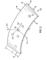
- the panel extends between a leading edge 46 and a trailing edge 48 and between first and second lateral (circumferential) edges 50 and 52 (FIG. 2).
- the panel may have one or more arrays of process air cooling holes 54 between the inner and outer surfaces and may have additional surface enhancements (not shown) on one or both of such surfaces as is known in the art or may be further developed.
- the inner surface 40 is circumferentially convex and has a center 60.
- FIG. 1 further shows a surface normal 510 and a conewise direction 512 normal thereto.
- the exemplary panel has a conical half angle ⁇ 1 , a longitudinal span L 1 , and a conewise span L 2 (FIG. 2).
- a radial direction is shown as 514.
- a circumferential direction is shown as 516.
- An angle spanned by the panel between the lateral edges about the engine centerline is shown as ⁇ 2 .
- ⁇ 2 is nominally 45° (e.g., slightly smaller to provide gaps between panels).
- FIG. 4 shows a main body wall portion 150 of an exemplary one of the panels (e.g., of the shields 37 and 38 or the bulkhead shield 31).
- the main portion has a local thickness T between an outboard surface portion 152 and the adjacent inboard surface portion 154 (e.g., of the surfaces 40 or 80).
- An array of film cooling holes or channels 160 extend between inlets 162 in the surface 152 and outlets 164 in the surface 154.
- the exemplary holes 160 are straight, having central longitudinal axes 530.
- Exemplary holes 160 have circular cross-sections normal to the axis 530 and having a diameter D.
- FIG. 5 shows a molded wax pattern 180 having the overall form of the heat shield panel but molded without the cooling holes.
- the pattern may be molded with portions corresponding to the panel main body, the process air cooling holes, perimeter and internal outboard reinforcement rails, and the like. After molding, features corresponding to the film cooling holes 160 may then be formed.
- FIG. 5 specifically shows a heated array 182 of probes 184 inserted into the pattern in a direction 540 (parallel to the ultimate axes 530) to form holes 185 corresponding to the cooling holes 160.
- a backing element 186 may be placed along one of the faces of the pattern. The backing element 186 may be pre-formed with apertures for receiving tip portions 188 of the probes as they pass through the pattern.
- the present methods may have one or more of several advantageous properties and uses.
- Mechanical drilling of cooling holes in a casting is increasingly difficult as the off-normal angle increases.
- casting may be particularly useful for providing film cooling holes.
- the spanning features 216 may tend to maintain the relative positions of the sidewalls 212 and 214 during casting. This may provide improved consistency of the thickness T among castings and uniformity of the thickness T within given castings. With such improved uniformity, the practicability of making a relatively thin casting is improved.
- an exemplary thickness T is advantageously less than 0.08 inch (2.0mm). More broadly, the thickness may be less than 0.12 inch (3.0mm) or 0.10 inch (2.5mm).
- the panel is engineered or manufactured as a drop-in replacement for an existing panel having drilled film cooling holes.
- the final thickness T may be approximately 0.06 inch (1.5mm) compared with a baseline thickness in excess of 0.08 inch (2.0mm).
- an exemplary diameter D is less than about 0.032 inch (0.81mm).
Landscapes
- Engineering & Computer Science (AREA)
- Mechanical Engineering (AREA)
- Chemical & Material Sciences (AREA)
- Combustion & Propulsion (AREA)
- General Engineering & Computer Science (AREA)
- Turbine Rotor Nozzle Sealing (AREA)
- Molds, Cores, And Manufacturing Methods Thereof (AREA)
- Mold Materials And Core Materials (AREA)
Abstract

Description
- The invention relates to turbine engines. More particularly, the invention relates to casting of cooled thin-wall components of gas turbine engines.
- Gas turbine engine combustor components such as heat shield and floatwall panels are commonly made of polycrystalline alloys. These components are exposed to extreme heat and thermal gradients during various phases of engine operation. Thermal-mechanical stresses and resulting fatigue contribute to component failure. Significant efforts are made to cool such components to provide durability. For example, to provide cooling of heat shield panels, the panels often include arrays of film cooling holes at angles off-normal to the surface facing the combustor interior. A low (shallow) angle through the panel (large off-normal angle) wall increases the surface area exposed to the air passing through the holes and, thereby, increases convective cooling. A low discharge angle provides the film cooling as the flow passes along the surface. Such cooling holes may be drilled in the cast panel (e.g., by laser drilling).
- One aspect of the invention involves a method for casting including molding a sacrificial pattern. After the molding, a plurality of holes are formed through the pattern. A shell is formed over the pattern including filling the holes. The pattern is destructively removed from the shell. A metallic material is cast in the shell. The shell is destructively removed.
- The details of one or more embodiments of the invention are set forth in the accompanying drawings and the description below. Other features, objects, and advantages of the invention will be apparent from the description and drawings, and from the claims.
-
- FIG. 1 is a longitudinal sectional view of a gas turbine engine combustor.
- FIG. 2 is a view of an inboard heat shield panel of the combustor of FIG. 1.
- FIG. 3 is a view of an outboard heat shield panel of the combustor of FIG. 1.
- FIG. 4 is a cross-sectional view of film cooling holes in one of the heat shield panels of FIGS. 2 and 3.
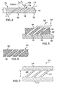
- FIG. 5 is a sectional view of a pattern along with an apparatus for forming the film cooling holes.
- FIG. 6 is a cross-sectional view of the pattern of FIG. 5 after a first shelling stage.
- FIG. 7 is a sectional view of a shell formed using the pattern of FIG. 6.
- FIG. 8 is a sectional view of a pattern in a pattern forming die including an inserted probe array.
- FIG. 9 is a sectional view of the pattern of FIG. 8 with the probe array retracted.
- Like reference numbers and designations in the various drawings indicate like elements.
- FIG. 1 shows a gas
turbine engine combustor 20. Theexemplary combustor 20 is generally annular about an engine central longitudinal axis (centerline) 500 parallel to which aforward direction 502 is illustrated. The exemplary combustor has two-layered inboard andoutboard walls walls bulkhead 26 at anupstream inlet 27 receiving air from the compressor section (not shown) to adownstream outlet 28 delivering air to the turbine section (not shown). A circumferential array of fuel injector/swirler assemblies 29 may be mounted in the bulkhead. - The bulkhead includes a
shell portion 30 and a heat shield 31 spaced aft/downstream thereof. The heat shield 31 may be formed by a circumferential array of bulkhead panels, at least some of which have apertures for accommodating associated ones of the injector/swirler assemblies. The combustor has an interior 34 aft/downstream of the bulkhead panel array. The inboard andoutboard walls outboard shell inner heat shield shields exemplary panel 37C, each panel has a generally inner (facing the interior 34)surface 40 and a generallyouter surface 42.Mounting studs 44 or other features may extend from theother surface 42 to secure the panel to the adjacent shell. The panel extends between a leadingedge 46 and atrailing edge 48 and between first and second lateral (circumferential)edges 50 and 52 (FIG. 2). The panel may have one or more arrays of processair cooling holes 54 between the inner and outer surfaces and may have additional surface enhancements (not shown) on one or both of such surfaces as is known in the art or may be further developed. - The
inner surface 40 is circumferentially convex and has acenter 60. FIG. 1 further shows a surface normal 510 and aconewise direction 512 normal thereto. The exemplary panel has a conical half angle θ1, a longitudinal span L1, and a conewise span L2 (FIG. 2). A radial direction is shown as 514. A circumferential direction is shown as 516. An angle spanned by the panel between the lateral edges about the engine centerline is shown as θ2. With an exemplary eight panels per ring, θ2 is nominally 45° (e.g., slightly smaller to provide gaps between panels). - Similarly, the
exemplary panel 38C has inner andouter surfaces trailing edges lateral edges 88 and 90 (FIG. 3). Theinner surface 80 is circumferentially concave and has acenter 100. A surface normal is shown as 520 and a conewise direction shown as 522. The conical half angle is shown as -θ3 (for reference, a negative angle will be associated with a rearwardly convergent cone) and the longitudinal span is shown as L3. A circumferential direction is shown as 524 in FIG. 3. A circumferential span is shown as θ4 and the conewise span is shown as L4. - FIG. 4 shows a main
body wall portion 150 of an exemplary one of the panels (e.g., of theshields outboard surface portion 152 and the adjacent inboard surface portion 154 (e.g., of thesurfaces 40 or 80). An array of film cooling holes orchannels 160 extend betweeninlets 162 in thesurface 152 andoutlets 164 in thesurface 154. Theexemplary holes 160 are straight, having centrallongitudinal axes 530.Exemplary holes 160 have circular cross-sections normal to theaxis 530 and having a diameter D. Theholes 160 extend off-normal to the localinboard surface portion 154 by an angle θ5, thus being off thesurface portion 154 by θ6, the complement of θ5. Theholes 160 may be grouped in regular or irregular arrays and may be distributed to provide a desired cooling profile. Exemplary θ5 are in excess of 45° (e.g., 50-70°) so that discharged air flows 170 provide a film cooling effect. - FIG. 5 shows a molded
wax pattern 180 having the overall form of the heat shield panel but molded without the cooling holes. For example, the pattern may be molded with portions corresponding to the panel main body, the process air cooling holes, perimeter and internal outboard reinforcement rails, and the like. After molding, features corresponding to the film cooling holes 160 may then be formed. FIG. 5 specifically shows aheated array 182 ofprobes 184 inserted into the pattern in a direction 540 (parallel to the ultimate axes 530) to formholes 185 corresponding to the cooling holes 160. To maintain pattern integrity, abacking element 186 may be placed along one of the faces of the pattern. Thebacking element 186 may be pre-formed with apertures for receivingtip portions 188 of the probes as they pass through the pattern. Alternatively, thebacking element 186 may be deformable to accommodate the tip portions. After insertion, the probe array may be retracted in the opposite direction. The probe array may displace material to create theholes 185. This may leaveelevations 190 at one or both faces. Theelevations 190 may be trimmed. Alternatively, the probes may be hollow and may evacuate the displaced material. - There may be multiple groups of the
holes 185. As noted above, the holes of the individual groups may have parallel axes. The holes of the different groups may have axes parallel to the axes of the holes of the other groups or not parallel thereto. For example, non-parallel axes may be appropriate to achieve desired flow patterns in the ultimate cast panel. Other drilling techniques for forming theholes 185 may be used including mechanical twist drilling. Theholes 185 may be formed individually or simultaneously in groups as noted above. - After the
holes 185 are formed in the pattern, the pattern may be shelled in a multi-stage stuccoing process. FIG. 6 shows thepattern 180 after a first slurry dip in the shelling process. The initial dip is typically in a thin and fine slurry to provide a smooth final interior surface for the ultimate shell. FIG. 6 shows alayer 200 of this slurry on both faces of the pattern main body and substantially filling the holes 185 (e.g., due to surface tension, havingslight recesses 202 at the ends of the holes). Further shelling steps may involve thicker and coarser slurries. After the final shelling step, the shell may be permitted to dry. The wax may be removed such as by a steam autoclave and/or shell firing (to harden the shell). - FIG. 7 shows the
shell 210 after wax removal. The shell has first andsecond sidewalls sidewalls shell interior 218. Upon introduction of cast metal to theshell interior 218, the spanningfeatures 216 form and define the film cooling holes 160. After the pouring and metal solidification, the shell may be destructively removed (by mechanical and/or chemical means). An exemplary removal involves mechanically breaking away thesidewalls - An alternative method of manufacture pre-forms the holes in the pattern as the wax material is molded. An array of probes or tines 250 (FIG. 8 - similarly arranged to the array 182) may be formed on a
slider element 252 of the pattern molding die 254. Theslider 252 is inserted into one of themain elements 256 of the die during die assembly and thewax 258 is molded around the slider probes 250. After wax cooling/hardening, the slider is then retracted (FIG. 9) to disengage theprobes 250 from the pattern, leaving theholes 185 and releasing a backlocking of the pattern relative to themain element 256. - The present methods may have one or more of several advantageous properties and uses. Mechanical drilling of cooling holes in a casting is increasingly difficult as the off-normal angle increases. Thus, casting may be particularly useful for providing film cooling holes. Additionally, the spanning features 216 may tend to maintain the relative positions of the
sidewalls - For a combustor heat shield, an exemplary thickness T is advantageously less than 0.08 inch (2.0mm). More broadly, the thickness may be less than 0.12 inch (3.0mm) or 0.10 inch (2.5mm). In an exemplary reengineering or remanufacturing situation, the panel is engineered or manufactured as a drop-in replacement for an existing panel having drilled film cooling holes. In this reengineering/remanufacturing situation, the final thickness T may be approximately 0.06 inch (1.5mm) compared with a baseline thickness in excess of 0.08 inch (2.0mm). For an exemplary panel thickness in the 0.06-0.08 inch (1.5-2.0mm) range, an exemplary diameter D is less than about 0.032 inch (0.81mm). Although particularly fine passageways may be more desirable, shell integrity issues may mitigate in favor of a diameter of 0.18-0.30 inch (0.46-0.76mm) range. More broadly, this diameter is advantageously less than the thickness and, more advantageously less than half the thickness. For non-circular sectioned holes, hole cross-sectional areas may be compared with the areas corresponding to these diameters. For the 0.46-0.81 diameter range corresponding areas are 0.16-0.52mm2. A narrower range would be 0.20-0.46mm2.
- One or more embodiments of the present invention have been described. Nevertheless, it will be understood that various modifications may be made without departing from the scope of the invention. For example, the principles may be applied to manufacture of exhaust nozzle liners and other thin wall cast structures. Where applied as a reengineering of an existing component, details of the existing component may influence or dictate details of any particular implementation. Accordingly, other embodiments are within the scope of the following claims.
Claims (26)
- A method for casting comprising:molding a sacrificial pattern (180);after said molding, forming a plurality of holes (185) through the pattern (180);forming a shell (200, 210) over the pattern (180) including filling the holes (185);destructively removing the pattern (180) from the shell (200); 210);casting a metallic material (150) in the shell (200; 210); anddestructively removing the shell (200; 210) from the metallic material (150).
- The method of claim 1 wherein:the shelling comprises a multi-stage stuccoing; anda first dip stage of said stuccoing essentially fills the holes (185).
- The method of claim 1 or 2 wherein:the forming of the plurality of holes (185) consists essentially of mechanical drilling.
- The method of claim 1 or 2 wherein:the forming of the plurality of holes (185) consists essentially of inserting at least one hot probe (184).
- The method of claim 4 wherein:the forming of the plurality of holes (185) consists essentially of inserting at least one hot probe (184) at an off-normal angle of 30-70°.
- The method of claim 4 or 5 wherein:the forming of the plurality of holes (185) consists essentially of inserting a plurality of hot probes (184) as a unit.
- The method of any preceding claim wherein:the plurality of holes (185) are formed with cross-sectional average transverse dimensions of less than half a local thickness.
- The method of any preceding claim wherein:the plurality of holes (185) are formed with cross-sectional areas of less than 0.52mm2.
- The method of claim 8 wherein:the plurality of holes (185) are formed with cross-sectional areas of 0.20-0.46mm2.
- The method of any of claims 1 to 7 wherein:the plurality of holes (185) are formed with cross-sectional areas of 0.16-0.52mm2.
- The method of any preceding claim used to manufacture a gas turbine engine combustor panel (150).
- A combustor panel investment casting pattern (180; 258) comprising a wax body formed as a generally frustoconical segment and having:a plurality of first through-holes (185) having:cross-sectional areas of less than 0.52mm2.
- The pattern of claim 12 wherein:the cross-sectional areas are 0.20-0.46mm2.
- The pattern of claim 12 or 13 wherein the wax body has:at least one second through hole having a diameter of at least 5cm.
- The pattern of claim 12, 13 or 14 wherein the wax body has:a perimeter rib on a first side, a second side being essentially frustoconical.
- The pattern of any of claims 12 to 15 wherein:a local thickness at said first through-holes is 1.5-2.0mm.
- The pattern of any of claims 12 to 15 wherein:a local thickness at said first through-holes (185) is less than 3.0mm.
- The pattern of any of claims 12 to 15 wherein:a local thickness at said first through-holes is less than 2 . 5mm .
- The pattern of any of claims 12 to 18 wherein:an off-normal angle of said first through-holes (185) is 30-70°.
- The pattern of any of claims 12 to 19 wherein:at least a first group of said first through-holes (185) are parallel.
- The pattern of claim 20 wherein:at least a second group of said first through-holes (185) are parallel, but are not parallel to the first group.
- A method for forming a cooled gas turbine engine component comprising:forming a sacrificial pattern (180) having a plurality of holes (185);forming a shell (200; 210) over the pattern including filling the holes;destructively removing the pattern (180) from the shell (200; 210);casting a metallic material (150) in the shell (200; 210); anddestructively removing the shell (200; 210) from the metallic material (150), the material forming the gas turbine engine component having film cooling holes (160) left by portions of the shell (200; 210) that had filled the holes (185).
- The method of 22 claim wherein:a local thickness of the pattern (180) at said holes (185) is less than 3.0mm;the holes (185) have cross-sectional areas of less than 0.52mm2; andthe holes (185) are at an angle off-normal to a local surface of the pattern by 30-70°.
- The method of claim 22 or 23 wherein the forming of the sacrificial pattern (180) comprises:assembling a die including a plurality of main elements (256) and a plurality of pins (250);injecting a wax material (258) into the die over the pins;extracting the plurality of pins (250) at least partially through at least one of the main elements (256); andremoving the pattern (180) from the main elements (256).
- A method for remanufacturing a gas turbine engine or reengineering a configuration thereof from a first configuration comprising a first combustor panel to a second configuration comprising a second combustor panel in place of the first combustor panel, wherein:the first combustor panel is formed as a generally frustoconical segment having a principal wall portion of an essentially constant first thickness and having a plurality of drilled cooling holes; andthe first combustor panel is formed as a generally frustoconical segment having a principal wall portion of an essentially constant second thickness, less than the first thickness, and having a plurality of cast cooling holes (160).
- The method of claim 25 wherein:the second combustor panel is a drop-in replacement for the first combustor panel.
Applications Claiming Priority (1)
| Application Number | Priority Date | Filing Date | Title |
|---|---|---|---|
| US11/216,278 US7325587B2 (en) | 2005-08-30 | 2005-08-30 | Method for casting cooling holes |
Publications (3)
| Publication Number | Publication Date |
|---|---|
| EP1760402A2 true EP1760402A2 (en) | 2007-03-07 |
| EP1760402A3 EP1760402A3 (en) | 2009-11-11 |
| EP1760402B1 EP1760402B1 (en) | 2014-11-19 |
Family
ID=37497459
Family Applications (1)
| Application Number | Title | Priority Date | Filing Date |
|---|---|---|---|
| EP06254324.4A Not-in-force EP1760402B1 (en) | 2005-08-30 | 2006-08-17 | Method for casting cooling holes |
Country Status (5)
| Country | Link |
|---|---|
| US (1) | US7325587B2 (en) |
| EP (1) | EP1760402B1 (en) |
| JP (1) | JP2007061907A (en) |
| KR (1) | KR100814995B1 (en) |
| CN (1) | CN1923405A (en) |
Cited By (2)
| Publication number | Priority date | Publication date | Assignee | Title |
|---|---|---|---|---|
| EP2527743A3 (en) * | 2011-05-25 | 2015-01-21 | Rolls-Royce Deutschland Ltd & Co KG | Segment component comprising high temperature cast material for an annular combustion chamber, annular combustion chamber for an aircraft engine, aircraft engine and method for producing an annular combustion chamber |
| EP1759788B1 (en) * | 2005-09-01 | 2017-01-18 | United Technologies Corporation | Investment casting of cooled turbine airfoils |
Families Citing this family (24)
| Publication number | Priority date | Publication date | Assignee | Title |
|---|---|---|---|---|
| CN102806313B (en) * | 2012-09-03 | 2014-07-30 | 贵州安吉航空精密铸造有限责任公司 | Method for preventing casting boss from shrinkage porosity |
| US9511388B2 (en) * | 2012-12-21 | 2016-12-06 | United Technologies Corporation | Method and system for holding a combustor panel during coating process |
| WO2015050879A1 (en) | 2013-10-04 | 2015-04-09 | United Technologies Corporation | Heat shield panels with overlap joints for a turbine engine combustor |
| JP6279915B2 (en) * | 2014-01-30 | 2018-02-14 | 株式会社神戸製鋼所 | Method for forming cast hole processed product and casing of screw compressor |
| EP3157694B1 (en) * | 2014-06-18 | 2020-07-29 | Mikro Systems Inc. | Turbine blade investment casting using film hole protrusions for integral wall thickness control |
| US9746184B2 (en) * | 2015-04-13 | 2017-08-29 | Pratt & Whitney Canada Corp. | Combustor dome heat shield |
| US10024190B1 (en) * | 2015-11-02 | 2018-07-17 | Florida Turbine Technologies, Inc. | Apparatus and process for forming an air cooled turbine airfoil with a cooling air channel and discharge slot in a thin wall |
| US10099283B2 (en) | 2015-12-17 | 2018-10-16 | General Electric Company | Method and assembly for forming components having an internal passage defined therein |
| US10099276B2 (en) | 2015-12-17 | 2018-10-16 | General Electric Company | Method and assembly for forming components having an internal passage defined therein |
| US10046389B2 (en) | 2015-12-17 | 2018-08-14 | General Electric Company | Method and assembly for forming components having internal passages using a jacketed core |
| US10118217B2 (en) | 2015-12-17 | 2018-11-06 | General Electric Company | Method and assembly for forming components having internal passages using a jacketed core |
| US9987677B2 (en) | 2015-12-17 | 2018-06-05 | General Electric Company | Method and assembly for forming components having internal passages using a jacketed core |
| US9968991B2 (en) | 2015-12-17 | 2018-05-15 | General Electric Company | Method and assembly for forming components having internal passages using a lattice structure |
| US10137499B2 (en) | 2015-12-17 | 2018-11-27 | General Electric Company | Method and assembly for forming components having an internal passage defined therein |
| US10099284B2 (en) | 2015-12-17 | 2018-10-16 | General Electric Company | Method and assembly for forming components having a catalyzed internal passage defined therein |
| US10150158B2 (en) | 2015-12-17 | 2018-12-11 | General Electric Company | Method and assembly for forming components having internal passages using a jacketed core |
| US9579714B1 (en) | 2015-12-17 | 2017-02-28 | General Electric Company | Method and assembly for forming components having internal passages using a lattice structure |
| US10335853B2 (en) | 2016-04-27 | 2019-07-02 | General Electric Company | Method and assembly for forming components using a jacketed core |
| US10286450B2 (en) | 2016-04-27 | 2019-05-14 | General Electric Company | Method and assembly for forming components using a jacketed core |
| CN110508750B (en) * | 2019-09-30 | 2021-02-09 | 西安皓森精铸有限公司 | Casting method of workpiece with partition plate in elongated hole |
| CN112238209A (en) * | 2020-10-16 | 2021-01-19 | 向孙团 | Manufacturing method of pulp molding stainless steel forming die |
| GB202210143D0 (en) | 2022-07-11 | 2022-08-24 | Rolls Royce Plc | Combustor casing component for a gas turbine engine |
| CN117620605B (en) * | 2023-11-28 | 2026-02-24 | 大连工业大学 | Processing method of nozzle for coke oven gas pre-desulfurization |
| CN121607574B (en) * | 2026-01-29 | 2026-04-14 | 上海万泽精密铸造有限公司 | Precise casting processing technology for lace screw of cavity combustion engine with electron beam perforation introduced |
Family Cites Families (12)
| Publication number | Priority date | Publication date | Assignee | Title |
|---|---|---|---|---|
| US3305358A (en) * | 1963-09-20 | 1967-02-21 | Howmet Corp | Method for shaping beryllium and other metals and ceramics |
| US3537949A (en) * | 1966-10-24 | 1970-11-03 | Rem Metals Corp | Investment shell molds for the high integrity precision casting of reactive and refractory metals,and methods for their manufacture |
| US3662816A (en) * | 1968-10-01 | 1972-05-16 | Trw Inc | Means for preventing core shift in casting articles |
| US5140869A (en) * | 1989-07-31 | 1992-08-25 | Ford Motor Company | Hollow connecting rod |
| US5295530A (en) * | 1992-02-18 | 1994-03-22 | General Motors Corporation | Single-cast, high-temperature, thin wall structures and methods of making the same |
| US5317805A (en) * | 1992-04-28 | 1994-06-07 | Minnesota Mining And Manufacturing Company | Method of making microchanneled heat exchangers utilizing sacrificial cores |
| US6626230B1 (en) * | 1999-10-26 | 2003-09-30 | Howmet Research Corporation | Multi-wall core and process |
| US6302185B1 (en) * | 2000-01-10 | 2001-10-16 | General Electric Company | Casting having an enhanced heat transfer surface, and mold and pattern for forming same |
| US6766850B2 (en) * | 2001-12-27 | 2004-07-27 | Caterpillar Inc | Pressure casting using a supported shell mold |
| US6668906B2 (en) * | 2002-04-29 | 2003-12-30 | United Technologies Corporation | Shaped core for cast cooling passages and enhanced part definition |
| JP4103812B2 (en) * | 2003-03-05 | 2008-06-18 | 株式会社Ihi | Mold manufacturing method |
| DE50311059D1 (en) * | 2003-10-29 | 2009-02-26 | Siemens Ag | mold |
-
2005
- 2005-08-30 US US11/216,278 patent/US7325587B2/en not_active Expired - Lifetime
-
2006
- 2006-07-25 KR KR1020060069611A patent/KR100814995B1/en not_active Expired - Fee Related
- 2006-08-17 EP EP06254324.4A patent/EP1760402B1/en not_active Not-in-force
- 2006-08-24 JP JP2006227375A patent/JP2007061907A/en active Pending
- 2006-08-30 CN CNA2006101517078A patent/CN1923405A/en active Pending
Non-Patent Citations (1)
| Title |
|---|
| None |
Cited By (2)
| Publication number | Priority date | Publication date | Assignee | Title |
|---|---|---|---|---|
| EP1759788B1 (en) * | 2005-09-01 | 2017-01-18 | United Technologies Corporation | Investment casting of cooled turbine airfoils |
| EP2527743A3 (en) * | 2011-05-25 | 2015-01-21 | Rolls-Royce Deutschland Ltd & Co KG | Segment component comprising high temperature cast material for an annular combustion chamber, annular combustion chamber for an aircraft engine, aircraft engine and method for producing an annular combustion chamber |
Also Published As
| Publication number | Publication date |
|---|---|
| JP2007061907A (en) | 2007-03-15 |
| EP1760402B1 (en) | 2014-11-19 |
| US7325587B2 (en) | 2008-02-05 |
| KR20070025986A (en) | 2007-03-08 |
| US20070044935A1 (en) | 2007-03-01 |
| KR100814995B1 (en) | 2008-03-18 |
| CN1923405A (en) | 2007-03-07 |
| EP1760402A3 (en) | 2009-11-11 |
Similar Documents
| Publication | Publication Date | Title |
|---|---|---|
| US7325587B2 (en) | Method for casting cooling holes | |
| US7216694B2 (en) | Apparatus and method for reducing operating stress in a turbine blade and the like | |
| US7841083B2 (en) | Method of manufacturing a turbomachine component that includes cooling air discharge orifices | |
| US7731481B2 (en) | Airfoil cooling with staggered refractory metal core microcircuits | |
| US7674093B2 (en) | Cluster bridged casting core | |
| US7438527B2 (en) | Airfoil trailing edge cooling | |
| US7780414B1 (en) | Turbine blade with multiple metering trailing edge cooling holes | |
| EP1635119A2 (en) | Cooled turbine engine components | |
| JP5449347B2 (en) | Manufacturing method of blade array parts | |
| EP2034132A2 (en) | Shroud segment with seal and corresponding manufacturing method | |
| EP2071126A2 (en) | Turbine blades and methods of manufacturing | |
| US20090087306A1 (en) | Blade outer air seals, cores, and manufacture methods | |
| CN107309403B (en) | Methods and assemblies for forming parts with jacketed cores | |
| EP3441673B1 (en) | Combustor panels having airflow distribution features | |
| EP3587927B1 (en) | Heat shield panel manufacturing process and heat shield panel | |
| EP3477202B1 (en) | Float wall combustor panels having airflow distribution features | |
| US20120319360A1 (en) | Plug assembly for blade outer air seal | |
| JP5270832B2 (en) | Airfoil for turbine blade and turbine blade | |
| CN105705265A (en) | Investment casting method for gas turbine engine vane segment | |
| EP3959024B1 (en) | Investment casting core with cooling feature alignment guide and related methods | |
| CN105705266A (en) | Ceramic casting core having an integral vane internal core and shroud backside shell for vane segment casting |
Legal Events
| Date | Code | Title | Description |
|---|---|---|---|
| PUAI | Public reference made under article 153(3) epc to a published international application that has entered the european phase |
Free format text: ORIGINAL CODE: 0009012 |
|
| AK | Designated contracting states |
Kind code of ref document: A2 Designated state(s): AT BE BG CH CY CZ DE DK EE ES FI FR GB GR HU IE IS IT LI LT LU LV MC NL PL PT RO SE SI SK TR |
|
| AX | Request for extension of the european patent |
Extension state: AL BA HR MK YU |
|
| PUAL | Search report despatched |
Free format text: ORIGINAL CODE: 0009013 |
|
| AK | Designated contracting states |
Kind code of ref document: A3 Designated state(s): AT BE BG CH CY CZ DE DK EE ES FI FR GB GR HU IE IS IT LI LT LU LV MC NL PL PT RO SE SI SK TR |
|
| AX | Request for extension of the european patent |
Extension state: AL BA HR MK RS |
|
| 17P | Request for examination filed |
Effective date: 20100511 |
|
| 17Q | First examination report despatched |
Effective date: 20100616 |
|
| AKX | Designation fees paid |
Designated state(s): DE GB |
|
| GRAP | Despatch of communication of intention to grant a patent |
Free format text: ORIGINAL CODE: EPIDOSNIGR1 |
|
| INTG | Intention to grant announced |
Effective date: 20140627 |
|
| GRAS | Grant fee paid |
Free format text: ORIGINAL CODE: EPIDOSNIGR3 |
|
| GRAA | (expected) grant |
Free format text: ORIGINAL CODE: 0009210 |
|
| AK | Designated contracting states |
Kind code of ref document: B1 Designated state(s): DE GB |
|
| REG | Reference to a national code |
Ref country code: GB Ref legal event code: FG4D |
|
| REG | Reference to a national code |
Ref country code: DE Ref legal event code: R081 Ref document number: 602006043693 Country of ref document: DE Owner name: UNITED TECHNOLOGIES CORP. (N.D.GES.D. STAATES , US Free format text: FORMER OWNER: UNITED TECHNOLOGIES CORP. (N.D.GES.D. STAATES DELAWARE), HARTFORD, CONN., US |
|
| REG | Reference to a national code |
Ref country code: DE Ref legal event code: R096 Ref document number: 602006043693 Country of ref document: DE Effective date: 20141231 |
|
| REG | Reference to a national code |
Ref country code: DE Ref legal event code: R097 Ref document number: 602006043693 Country of ref document: DE |
|
| PLBE | No opposition filed within time limit |
Free format text: ORIGINAL CODE: 0009261 |
|
| STAA | Information on the status of an ep patent application or granted ep patent |
Free format text: STATUS: NO OPPOSITION FILED WITHIN TIME LIMIT |
|
| 26N | No opposition filed |
Effective date: 20150820 |
|
| REG | Reference to a national code |
Ref country code: DE Ref legal event code: R082 Ref document number: 602006043693 Country of ref document: DE Representative=s name: SCHMITT-NILSON SCHRAUD WAIBEL WOHLFROM PATENTA, DE |
|
| REG | Reference to a national code |
Ref country code: DE Ref legal event code: R082 Ref document number: 602006043693 Country of ref document: DE Representative=s name: SCHMITT-NILSON SCHRAUD WAIBEL WOHLFROM PATENTA, DE Ref country code: DE Ref legal event code: R081 Ref document number: 602006043693 Country of ref document: DE Owner name: UNITED TECHNOLOGIES CORP. (N.D.GES.D. STAATES , US Free format text: FORMER OWNER: UNITED TECHNOLOGIES CORP., HARTFORD, CONN., US |
|
| PGFP | Annual fee paid to national office [announced via postgrant information from national office to epo] |
Ref country code: DE Payment date: 20190722 Year of fee payment: 14 |
|
| PGFP | Annual fee paid to national office [announced via postgrant information from national office to epo] |
Ref country code: GB Payment date: 20190722 Year of fee payment: 14 |
|
| REG | Reference to a national code |
Ref country code: DE Ref legal event code: R119 Ref document number: 602006043693 Country of ref document: DE |
|
| GBPC | Gb: european patent ceased through non-payment of renewal fee |
Effective date: 20200817 |
|
| PG25 | Lapsed in a contracting state [announced via postgrant information from national office to epo] |
Ref country code: DE Free format text: LAPSE BECAUSE OF NON-PAYMENT OF DUE FEES Effective date: 20210302 |
|
| PG25 | Lapsed in a contracting state [announced via postgrant information from national office to epo] |
Ref country code: GB Free format text: LAPSE BECAUSE OF NON-PAYMENT OF DUE FEES Effective date: 20200817 |