EP1760304A1 - Integrated air-fuel manifold for an internal combustion engine, and relative production method - Google Patents
Integrated air-fuel manifold for an internal combustion engine, and relative production method Download PDFInfo
- Publication number
- EP1760304A1 EP1760304A1 EP05425618A EP05425618A EP1760304A1 EP 1760304 A1 EP1760304 A1 EP 1760304A1 EP 05425618 A EP05425618 A EP 05425618A EP 05425618 A EP05425618 A EP 05425618A EP 1760304 A1 EP1760304 A1 EP 1760304A1
- Authority
- EP
- European Patent Office
- Prior art keywords
- fuel manifold
- manifold
- fuel
- integrated air
- intake
- Prior art date
- Legal status (The legal status is an assumption and is not a legal conclusion. Google has not performed a legal analysis and makes no representation as to the accuracy of the status listed.)
- Withdrawn
Links
- 239000000446 fuel Substances 0.000 title claims abstract description 120
- 238000002485 combustion reaction Methods 0.000 title claims abstract description 13
- 238000004519 manufacturing process Methods 0.000 title description 9
- 239000000463 material Substances 0.000 claims abstract description 52
- 238000000034 method Methods 0.000 claims description 13
- 238000002347 injection Methods 0.000 claims description 10
- 239000007924 injection Substances 0.000 claims description 10
- 239000004033 plastic Substances 0.000 claims description 9
- 239000010935 stainless steel Substances 0.000 claims description 7
- 229910001220 stainless steel Inorganic materials 0.000 claims description 7
- 238000004512 die casting Methods 0.000 claims description 2
- 229920001169 thermoplastic Polymers 0.000 claims description 2
- 229920001187 thermosetting polymer Polymers 0.000 claims description 2
- 239000007769 metal material Substances 0.000 claims 2
- 239000004411 aluminium Substances 0.000 description 9
- 229910052782 aluminium Inorganic materials 0.000 description 9
- XAGFODPZIPBFFR-UHFFFAOYSA-N aluminium Chemical compound [Al] XAGFODPZIPBFFR-UHFFFAOYSA-N 0.000 description 9
- 238000005260 corrosion Methods 0.000 description 7
- 230000007797 corrosion Effects 0.000 description 7
- 229910000831 Steel Inorganic materials 0.000 description 6
- 239000010959 steel Substances 0.000 description 6
- 238000003754 machining Methods 0.000 description 4
- 229910052751 metal Inorganic materials 0.000 description 4
- 239000002184 metal Substances 0.000 description 4
- OKKJLVBELUTLKV-UHFFFAOYSA-N Methanol Chemical compound OC OKKJLVBELUTLKV-UHFFFAOYSA-N 0.000 description 3
- 229920000642 polymer Polymers 0.000 description 3
- LFQSCWFLJHTTHZ-UHFFFAOYSA-N Ethanol Natural products CCO LFQSCWFLJHTTHZ-UHFFFAOYSA-N 0.000 description 2
- PXHVJJICTQNCMI-UHFFFAOYSA-N Nickel Chemical compound [Ni] PXHVJJICTQNCMI-UHFFFAOYSA-N 0.000 description 2
- VNWKTOKETHGBQD-UHFFFAOYSA-N methane Chemical compound C VNWKTOKETHGBQD-UHFFFAOYSA-N 0.000 description 2
- 239000002991 molded plastic Substances 0.000 description 2
- 239000000243 solution Substances 0.000 description 2
- 239000000126 substance Substances 0.000 description 2
- 230000009974 thixotropic effect Effects 0.000 description 2
- 238000003466 welding Methods 0.000 description 2
- 229910000990 Ni alloy Inorganic materials 0.000 description 1
- 239000004677 Nylon Substances 0.000 description 1
- 229920000122 acrylonitrile butadiene styrene Polymers 0.000 description 1
- 239000004676 acrylonitrile butadiene styrene Substances 0.000 description 1
- 238000005266 casting Methods 0.000 description 1
- 239000003054 catalyst Substances 0.000 description 1
- 239000002283 diesel fuel Substances 0.000 description 1
- 239000003822 epoxy resin Substances 0.000 description 1
- 125000001495 ethyl group Chemical group [H]C([H])([H])C([H])([H])* 0.000 description 1
- 239000007789 gas Substances 0.000 description 1
- 238000002844 melting Methods 0.000 description 1
- 230000008018 melting Effects 0.000 description 1
- 229910052759 nickel Inorganic materials 0.000 description 1
- 229920001778 nylon Polymers 0.000 description 1
- 229920000647 polyepoxide Polymers 0.000 description 1
- 230000003134 recirculating effect Effects 0.000 description 1
- 239000004416 thermosoftening plastic Substances 0.000 description 1
- 238000011144 upstream manufacturing Methods 0.000 description 1
Images


Classifications
-
- F—MECHANICAL ENGINEERING; LIGHTING; HEATING; WEAPONS; BLASTING
- F02—COMBUSTION ENGINES; HOT-GAS OR COMBUSTION-PRODUCT ENGINE PLANTS
- F02M—SUPPLYING COMBUSTION ENGINES IN GENERAL WITH COMBUSTIBLE MIXTURES OR CONSTITUENTS THEREOF
- F02M69/00—Low-pressure fuel-injection apparatus ; Apparatus with both continuous and intermittent injection; Apparatus injecting different types of fuel
- F02M69/46—Details, component parts or accessories not provided for in, or of interest apart from, the apparatus covered by groups F02M69/02 - F02M69/44
- F02M69/462—Arrangement of fuel conduits, e.g. with valves for maintaining pressure in the pipes after the engine being shut-down
- F02M69/465—Arrangement of fuel conduits, e.g. with valves for maintaining pressure in the pipes after the engine being shut-down of fuel rails
-
- F—MECHANICAL ENGINEERING; LIGHTING; HEATING; WEAPONS; BLASTING
- F02—COMBUSTION ENGINES; HOT-GAS OR COMBUSTION-PRODUCT ENGINE PLANTS
- F02M—SUPPLYING COMBUSTION ENGINES IN GENERAL WITH COMBUSTIBLE MIXTURES OR CONSTITUENTS THEREOF
- F02M35/00—Combustion-air cleaners, air intakes, intake silencers, or induction systems specially adapted for, or arranged on, internal-combustion engines
- F02M35/10—Air intakes; Induction systems
- F02M35/10006—Air intakes; Induction systems characterised by the position of elements of the air intake system in direction of the air intake flow, i.e. between ambient air inlet and supply to the combustion chamber
- F02M35/10078—Connections of intake systems to the engine
-
- F—MECHANICAL ENGINEERING; LIGHTING; HEATING; WEAPONS; BLASTING
- F02—COMBUSTION ENGINES; HOT-GAS OR COMBUSTION-PRODUCT ENGINE PLANTS
- F02M—SUPPLYING COMBUSTION ENGINES IN GENERAL WITH COMBUSTIBLE MIXTURES OR CONSTITUENTS THEREOF
- F02M35/00—Combustion-air cleaners, air intakes, intake silencers, or induction systems specially adapted for, or arranged on, internal-combustion engines
- F02M35/10—Air intakes; Induction systems
- F02M35/10209—Fluid connections to the air intake system; their arrangement of pipes, valves or the like
- F02M35/10216—Fuel injectors; Fuel pipes or rails; Fuel pumps or pressure regulators
-
- F—MECHANICAL ENGINEERING; LIGHTING; HEATING; WEAPONS; BLASTING
- F02—COMBUSTION ENGINES; HOT-GAS OR COMBUSTION-PRODUCT ENGINE PLANTS
- F02M—SUPPLYING COMBUSTION ENGINES IN GENERAL WITH COMBUSTIBLE MIXTURES OR CONSTITUENTS THEREOF
- F02M35/00—Combustion-air cleaners, air intakes, intake silencers, or induction systems specially adapted for, or arranged on, internal-combustion engines
- F02M35/10—Air intakes; Induction systems
- F02M35/10242—Devices or means connected to or integrated into air intakes; Air intakes combined with other engine or vehicle parts
- F02M35/10288—Air intakes combined with another engine part, e.g. cylinder head cover or being cast in one piece with the exhaust manifold, cylinder head or engine block
-
- F—MECHANICAL ENGINEERING; LIGHTING; HEATING; WEAPONS; BLASTING
- F02—COMBUSTION ENGINES; HOT-GAS OR COMBUSTION-PRODUCT ENGINE PLANTS
- F02M—SUPPLYING COMBUSTION ENGINES IN GENERAL WITH COMBUSTIBLE MIXTURES OR CONSTITUENTS THEREOF
- F02M35/00—Combustion-air cleaners, air intakes, intake silencers, or induction systems specially adapted for, or arranged on, internal-combustion engines
- F02M35/10—Air intakes; Induction systems
- F02M35/10314—Materials for intake systems
- F02M35/10321—Plastics; Composites; Rubbers
-
- F—MECHANICAL ENGINEERING; LIGHTING; HEATING; WEAPONS; BLASTING
- F02—COMBUSTION ENGINES; HOT-GAS OR COMBUSTION-PRODUCT ENGINE PLANTS
- F02M—SUPPLYING COMBUSTION ENGINES IN GENERAL WITH COMBUSTIBLE MIXTURES OR CONSTITUENTS THEREOF
- F02M35/00—Combustion-air cleaners, air intakes, intake silencers, or induction systems specially adapted for, or arranged on, internal-combustion engines
- F02M35/10—Air intakes; Induction systems
- F02M35/1034—Manufacturing and assembling intake systems
- F02M35/10354—Joining multiple sections together
- F02M35/1036—Joining multiple sections together by welding, bonding or the like
Definitions
- the present invention relates to an integrated air-fuel manifold for an internal combustion engine, and relative production method.
- the present invention may be used to particular advantage in a direct-petrol-injection, internal combustion engine, to which the following description refers purely by way of example.
- pressurized petrol is fed to a fuel manifold connected to a number of injectors (one for each engine cylinder), which are activated cyclically to inject part of the pressurized petrol in the fuel manifold directly into the respective cylinders.
- the petrol in the fuel manifold is at fairly low pressure (normally 2 to 4 atmospheres). Consequently, fuel manifolds of indirect-petrol-injection engines are currently made of plastic material (typically, molded engineering polymers), on the grounds that it is easy to process and cheap.
- the intake (or air) manifold is also made of plastic material and fixed by screws to the fuel manifold.
- the petrol pressure in the fuel manifold of a direct-petrol-injection engine is fairly high (currently between 100 and 200 atmospheres).
- a plastic fuel manifold has poor mechanical characteristics, and is therefore unable to safely withstand the relatively high petrol pressures typical of direct petrol injection.
- a shell-cast aluminium fuel manifold has been proposed, but is also expensive to produce, on account of shell casting being a relatively slow process, requiring numerous machining operations once the piece is removed from the mold, and imposing minimum piece thicknesses of 4-5 mm.
- die-casting using thixotropic aluminium has been proposed. Tests, however, show aluminium fuel manifolds fail to provide for consistent, satisfactory mechanical strength, particularly with petrol pressures in the fuel manifold of over 150 atmospheres.
- an aluminium fuel manifold fails to ensure satisfactory resistance to corrosion by various currently marketed fuels (in particular containing large percentages of ethyl or methyl alcohol), so that the petrol-exposed parts of the fuel manifold must be anodized or nickel plated. Both are complex, high-cost processes which tests have shown do not always succeed in ensuring the necessary corrosion resistance, particularly on account of the relatively high temperature of the petrol in the fuel manifold (even exceeding 100°C) during normal operation of the engine.
- a two-material fuel manifold comprising a steel feed conduit for feeding the pressurized fuel to the injectors; and a connecting body, which incorporates the feed conduit, provides for mechanically connecting the fuel manifold inside the engine, is made of molded plastic or cast aluminium, and is produced by forming the plastic material or aluminium in a mold containing the feed conduit.
- the fuel manifold is normally fixed to the intake (or air) manifold at the interface with the cylinder head. Because of the high operating pressure and the strict requirements imposed by the location of the fuel manifold, complex, dedicated systems are required, designed to support and fasten the fuel manifold firmly and reliably. These problems apply, to a greater or lesser extent, to any type of engine featuring a fuel manifold fixed to an air manifold.
- Conventional manufacturing solutions comprise steel fuel manifolds, to which metal brackets are soldered, and which are fitted by screws to air manifolds normally made of injection-molded engineering polymers. The metal brackets, however, being specially designed for individual applications, have a manufacturing cost which is partly determined by the impossibility of exploiting standard engine layouts.
- an integrated air-fuel manifold for an internal combustion engine and relative production method, as recited in the accompanying Claims.
- Number 1 in Figure 1 indicates as a whole an internal combustion engine comprising a cylinder head 2, in which are formed four cylinders 3 (only one shown in Figure 1), each of which is connected to an intake (or air) manifold 4 by at least one intake valve 5, and to an exhaust manifold 6 by at least one exhaust valve 7.
- Intake manifold 4 is supplied with fresh air (i.e. from outside) via a throttle valve 8 adjustable between a closed position and a fully-open position.
- An exhaust pipe 9 extends from exhaust manifold 6, and has one or more catalysts (not shown) for emitting into the atmosphere the gases produced by combustion in cylinders 3.
- a low-pressure pump feeds petrol from a tank (not shown) to a high-pressure pump 10, which in turn feeds the petrol to a fuel manifold 11.
- a number of injectors 12 are connected to fuel manifold 11, and each is activated cyclically to inject part of the pressurized petrol in fuel manifold 11 into respective cylinder 3.
- the petrol in fuel manifold 11 is maintained instant by instant at a desired pressure by a pressure regulator 13 connected to fuel manifold 11, and which drains any surplus petrol into a recirculating channel, by which the surplus petrol is fed back to a point upstream from the low-pressure pump (not shown).
- Fuel manifold 11 is also fitted with a sensor 14 to measure the pressure of the petrol in fuel manifold 11.
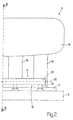
- intake manifold 4 comprises an elongated main body 15 connected to throttle valve 8, and from which originate four intake pipes 16 (only two shown in Figure 2), each connecting main body 15 to a cylinder 3. More specifically, each intake pipe 16 terminates with a connecting flange 17, which is common to all of intake pipes 16 and provides for fitting intake manifold 4 to cylinder head 2 of engine 1.
- Intake manifold 4 also comprises a housing body 18 positioned contacting both connecting flange 17 and intake pipes 16, and incorporating fuel manifold 11.
- fuel manifold 11 is incorporated inside intake manifold 4 or, more specifically, inside housing body 18 of intake manifold 4, so that intake manifold 4 and fuel manifold 11 form an integrated air-fuel manifold.
- Fuel manifold 11 comprises a cylindrical tubular main channel 19 having a central axis 20 of symmetry, and which distributes pressurized petrol to injectors 12. From main channel 19 extend four cylindrical tubular secondary channels (or bowls) 21, each of which is perpendicular to main channel 19 and houses a top portion of an injector 12 in fluidtight manner.
- main channel 19 has two open opposite ends 22 and 23; end 22 is connected to high-pressure pump 10 to feed pressurized petrol to fuel manifold 11; and end 23 is closed by a screw cap (not shown), and provides for easier, more precise manufacture of main channel 19 when forming fuel manifold 11. Close to end 23, main channel 19 has an opening (not shown) for receiving pressure regulator 13, and another opening (not shown) for receiving pressure sensor 14.
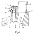
- Figure 4 shows an alternative embodiment of the integrated air-fuel manifold, which substantially differs as regards the shape of connecting flange 17 and housing body 18.
- Intake manifold 4 (comprising main body 15, intake pipes 16, connecting flange 17, and housing body 18) is made of molded plastic material, whereas fuel manifold 11 is made of steel.
- intake manifold 4 which is complex in shape and not subjected to severe mechanical or chemical stress, is made of a first material which is cheap, easy to work, and of low strength; whereas fuel manifold 11, which is simple in shape and subjected to severe mechanical and chemical stress, is made of a second material which is more expensive, more complex to work, and of high strength.
- the first material of intake manifold 4 is one which is cheap and easy to work.
- the first material of intake manifold 4 is a thermoplastic or thermosetting plastic material, such as an engineering polymer, ABS, nylon, or epoxy resin.
- the first material of intake manifold 4 may be a metal, such as aluminium or thixotropic aluminium.
- An important requirement of the first material is that it have a lower melting point than the second material, so that the first material can be formed inside a mold containing fuel manifold 11, made of the second material, without damaging or deforming fuel manifold 11.
- the second material of fuel manifold 11 is one of both good mechanical strength and good corrosion resistance, preferably stainless steel (e.g. a series 300 stainless steel, such as stainless steel 316).
- stainless steel e.g. a series 300 stainless steel, such as stainless steel 316.
- the second material of fuel manifold 11 may be a nickel alloy.
- the integrated air-fuel manifold therefore comprises an intake manifold 4, which is made of a first (plastic) material, provides for mechanical connection to cylinder head 2 of engine 1, and feeds air to cylinders 3; and a fuel manifold 11, which is made of a second material (stainless steel), is incorporated in housing body 18 of intake manifold 4, and distributes pressurized petrol to injectors 12.
- the integrated air-fuel manifold comprising intake manifold 4 and fuel manifold 11, as described above, is produced by producing steel fuel manifold 11 separately from intake manifold 4; placing fuel manifold 11 inside a known mold (not shown) negatively reproducing the shape of intake manifold 4; and feeding plastic material into the mold to form intake manifold 4 around fuel manifold 11.
- the plastic material is preferably injected into the mold containing fuel manifold 11.
- Fuel manifold 11 may be produced by either welding secondary channels 21 to main channel 19, or hydroforming a one-piece metal pipe.
- fuel manifold 11 is substantially embedded inside housing body 18 of intake manifold 4. That is, housing body 18 of intake manifold 4 encases substantially the whole of fuel manifold 11, but obviously leaves exposed, and accessible from outside, at least end 22 of main channel 19, which must be connected to high-pressure pump 10; the open ends of secondary channels 21, for receiving injectors 12; and the openings (not shown) for pressure regulator 13 and pressure sensor 14.
- the integrated air-fuel manifold therefore comprises an inner part (fuel manifold 11) and an outer part (intake manifold 4), which perform different functions, are made of different materials, and are produced using two different manufacturing techniques.
- the integrated air-fuel manifold comprising intake manifold 4 and fuel manifold 11, as described above, is extremely cheap and easy to produce, reduces assembly time of engine 1, and at the same time provides for excellent resistance to fuel pressure and fuel-induced corrosion.
- the integrated air-fuel manifold described above is cheap and easy to produce, by making intake manifold 4, which is complex in shape, from a first low-cost material that is easy to work, and by making fuel manifold 11, which is simple in shape, from a second material that is more difficult to work.
- the fuel manifold described above may obviously also be used to advantage in an internal combustion engine fuelled with other than petrol, such as LPG, methane, alcohol, or diesel fuel.
Landscapes
- Engineering & Computer Science (AREA)
- Chemical & Material Sciences (AREA)
- Combustion & Propulsion (AREA)
- Mechanical Engineering (AREA)
- General Engineering & Computer Science (AREA)
- Manufacturing & Machinery (AREA)
- Fuel-Injection Apparatus (AREA)
Abstract
An integrated air-fuel manifold for an internal combustion engine (1) having a number of cylinders (3) formed in a cylinder head (2). The integrated air-fuel manifold has an intake manifold (4) which is made of a first material, supplies air to the cylinders (3), and has connecting means for mechanical connection to the cylinder head (2) of the engine (1); and a fuel manifold (11) which is made of a second material, different from the first material, distributes pressurized fuel to injectors (12) fitted to the cylinders (3), and is incorporated in the intake manifold (4).
Description
- The present invention relates to an integrated air-fuel manifold for an internal combustion engine, and relative production method.
- The present invention may be used to particular advantage in a direct-petrol-injection, internal combustion engine, to which the following description refers purely by way of example.
- The past few years have seen a continual increase in sales of direct-petrol-injection, internal combustion engines. In an engine of this sort, pressurized petrol is fed to a fuel manifold connected to a number of injectors (one for each engine cylinder), which are activated cyclically to inject part of the pressurized petrol in the fuel manifold directly into the respective cylinders.
- In an indirect-petrol-injection engine, the petrol in the fuel manifold is at fairly low pressure (normally 2 to 4 atmospheres). Consequently, fuel manifolds of indirect-petrol-injection engines are currently made of plastic material (typically, molded engineering polymers), on the grounds that it is easy to process and cheap. In an indirect-petrol-injection engine, the intake (or air) manifold is also made of plastic material and fixed by screws to the fuel manifold.
- Conversely, the petrol pressure in the fuel manifold of a direct-petrol-injection engine is fairly high (currently between 100 and 200 atmospheres). A plastic fuel manifold has poor mechanical characteristics, and is therefore unable to safely withstand the relatively high petrol pressures typical of direct petrol injection.
- To ensure the necessary mechanical strength, known direct-petrol-injection engines employ all-steel fuel manifolds, which are expensive to produce, on account of the amount of machining and welding involved. Moreover, this solution calls for fitting the steel fuel manifold with a connecting flange for connection to the intake (or air) manifold, and which must be machined separately, thus further increasing machining cost.
- A shell-cast aluminium fuel manifold has been proposed, but is also expensive to produce, on account of shell casting being a relatively slow process, requiring numerous machining operations once the piece is removed from the mold, and imposing minimum piece thicknesses of 4-5 mm. To reduce the machining cost of cast aluminium fuel manifolds, die-casting using thixotropic aluminium has been proposed. Tests, however, show aluminium fuel manifolds fail to provide for consistent, satisfactory mechanical strength, particularly with petrol pressures in the fuel manifold of over 150 atmospheres. Moreover, an aluminium fuel manifold fails to ensure satisfactory resistance to corrosion by various currently marketed fuels (in particular containing large percentages of ethyl or methyl alcohol), so that the petrol-exposed parts of the fuel manifold must be anodized or nickel plated. Both are complex, high-cost processes which tests have shown do not always succeed in ensuring the necessary corrosion resistance, particularly on account of the relatively high temperature of the petrol in the fuel manifold (even exceeding 100°C) during normal operation of the engine.
- As described in Patent Application
IT2004BO00114 - As stated, the fuel manifold is normally fixed to the intake (or air) manifold at the interface with the cylinder head. Because of the high operating pressure and the strict requirements imposed by the location of the fuel manifold, complex, dedicated systems are required, designed to support and fasten the fuel manifold firmly and reliably. These problems apply, to a greater or lesser extent, to any type of engine featuring a fuel manifold fixed to an air manifold. Conventional manufacturing solutions comprise steel fuel manifolds, to which metal brackets are soldered, and which are fitted by screws to air manifolds normally made of injection-molded engineering polymers. The metal brackets, however, being specially designed for individual applications, have a manufacturing cost which is partly determined by the impossibility of exploiting standard engine layouts.
- It is an object of the present invention to provide an integrated air-fuel manifold for an internal combustion engine, and relative production method; which manifold and method are designed to eliminate the aforementioned drawbacks and, in particular, are cheap and easy to implement.
- According to the present invention, there are provided an integrated air-fuel manifold for an internal combustion engine, and relative production method, as recited in the accompanying Claims.
- A number of non-limiting embodiments of the present invention will be described by way of example with reference to the accompanying drawings, in which:
- Figure 1 shows a schematic view of a direct-petrol-injection, internal combustion engine featuring an integrated air-fuel manifold in accordance with the present invention;
- Figure 2 shows a schematic front view of part of the Figure 1 integrated air-fuel manifold fitted to a cylinder head of the Figure 1 engine;
- Figure 3 shows a lateral section along line III-III of the Figure 2 integrated air-fuel manifold;
- Figure 4 shows a schematic lateral section of part of an alternative embodiment of an integrated air-fuel manifold fitted to a cylinder head of the Figure 1 engine.
-
Number 1 in Figure 1 indicates as a whole an internal combustion engine comprising acylinder head 2, in which are formed four cylinders 3 (only one shown in Figure 1), each of which is connected to an intake (or air)manifold 4 by at least oneintake valve 5, and to anexhaust manifold 6 by at least oneexhaust valve 7.Intake manifold 4 is supplied with fresh air (i.e. from outside) via athrottle valve 8 adjustable between a closed position and a fully-open position. Anexhaust pipe 9 extends fromexhaust manifold 6, and has one or more catalysts (not shown) for emitting into the atmosphere the gases produced by combustion incylinders 3. - A low-pressure pump (not shown) feeds petrol from a tank (not shown) to a high-
pressure pump 10, which in turn feeds the petrol to afuel manifold 11. A number of injectors 12 (one for each cylinder 3) are connected tofuel manifold 11, and each is activated cyclically to inject part of the pressurized petrol infuel manifold 11 intorespective cylinder 3. The petrol infuel manifold 11 is maintained instant by instant at a desired pressure by apressure regulator 13 connected tofuel manifold 11, and which drains any surplus petrol into a recirculating channel, by which the surplus petrol is fed back to a point upstream from the low-pressure pump (not shown).Fuel manifold 11 is also fitted with asensor 14 to measure the pressure of the petrol infuel manifold 11. - As shown more clearly in Figures 2 and 3,
intake manifold 4 comprises an elongatedmain body 15 connected tothrottle valve 8, and from which originate four intake pipes 16 (only two shown in Figure 2), each connectingmain body 15 to acylinder 3. More specifically, eachintake pipe 16 terminates with a connectingflange 17, which is common to all ofintake pipes 16 and provides forfitting intake manifold 4 tocylinder head 2 ofengine 1.Intake manifold 4 also comprises ahousing body 18 positioned contacting both connectingflange 17 andintake pipes 16, and incorporatingfuel manifold 11. In other words,fuel manifold 11 is incorporated insideintake manifold 4 or, more specifically, insidehousing body 18 ofintake manifold 4, so thatintake manifold 4 andfuel manifold 11 form an integrated air-fuel manifold. -
Fuel manifold 11 comprises a cylindrical tubularmain channel 19 having acentral axis 20 of symmetry, and which distributes pressurized petrol toinjectors 12. Frommain channel 19 extend four cylindrical tubular secondary channels (or bowls) 21, each of which is perpendicular tomain channel 19 and houses a top portion of aninjector 12 in fluidtight manner. As shown in Figure 1,main channel 19 has two openopposite ends end 22 is connected to high-pressure pump 10 to feed pressurized petrol tofuel manifold 11; andend 23 is closed by a screw cap (not shown), and provides for easier, more precise manufacture ofmain channel 19 when formingfuel manifold 11. Close toend 23,main channel 19 has an opening (not shown) for receivingpressure regulator 13, and another opening (not shown) for receivingpressure sensor 14. - Figure 4 shows an alternative embodiment of the integrated air-fuel manifold, which substantially differs as regards the shape of connecting
flange 17 andhousing body 18. - Intake manifold 4 (comprising
main body 15,intake pipes 16, connectingflange 17, and housing body 18) is made of molded plastic material, whereasfuel manifold 11 is made of steel. In other words,intake manifold 4, which is complex in shape and not subjected to severe mechanical or chemical stress, is made of a first material which is cheap, easy to work, and of low strength; whereasfuel manifold 11, which is simple in shape and subjected to severe mechanical and chemical stress, is made of a second material which is more expensive, more complex to work, and of high strength. An important point to note is that mechanical connection offuel manifold 11 tocylinder head 2 ofengine 1 is achieved by mechanically connectingintake manifold 4 tocylinder head 2 ofengine 1; and mechanical connection offuel manifold 11 to intakemanifold 4 is achieved by incorporatingfuel manifold 11 insideintake manifold 4. As a result,fuel manifold 11 is extremely simple and linear in shape, by requiring no connecting elements (bored flanges or similar). - Since
intake manifold 4 does not come into contact with the petrol, and therefore need withstand neither petrol pressure nor petrol-induced corrosion, the first material ofintake manifold 4 is one which is cheap and easy to work. Preferably, the first material ofintake manifold 4 is a thermoplastic or thermosetting plastic material, such as an engineering polymer, ABS, nylon, or epoxy resin. Alternatively, if greater mechanical strength is required, the first material ofintake manifold 4 may be a metal, such as aluminium or thixotropic aluminium. An important requirement of the first material is that it have a lower melting point than the second material, so that the first material can be formed inside a mold containingfuel manifold 11, made of the second material, without damaging or deformingfuel manifold 11. - Since
fuel manifold 11, in use, comes into contact with pressurized petrol, the second material offuel manifold 11 is one of both good mechanical strength and good corrosion resistance, preferably stainless steel (e.g. a series 300 stainless steel, such as stainless steel 316). Alternatively, if greater corrosion resistance than that of stainless steel is required, the second material offuel manifold 11 may be a nickel alloy. - It is important to note that petrol pressure resistance is entrusted solely to
fuel manifold 11. That is to say, though the mechanical strength offuel manifold 11 is enhanced slightly byhousing body 18 surrounding it,fuel manifold 11 is nevertheless designed to withstand fuel pressure unaided. - The integrated air-fuel manifold therefore comprises an
intake manifold 4, which is made of a first (plastic) material, provides for mechanical connection tocylinder head 2 ofengine 1, and feeds air tocylinders 3; and afuel manifold 11, which is made of a second material (stainless steel), is incorporated inhousing body 18 ofintake manifold 4, and distributes pressurized petrol toinjectors 12. - The integrated air-fuel manifold comprising
intake manifold 4 andfuel manifold 11, as described above, is produced by producingsteel fuel manifold 11 separately fromintake manifold 4; placingfuel manifold 11 inside a known mold (not shown) negatively reproducing the shape ofintake manifold 4; and feeding plastic material into the mold to formintake manifold 4 aroundfuel manifold 11. The plastic material is preferably injected into the mold containingfuel manifold 11.Fuel manifold 11 may be produced by either weldingsecondary channels 21 tomain channel 19, or hydroforming a one-piece metal pipe. - Operating as described above,
fuel manifold 11 is substantially embedded insidehousing body 18 ofintake manifold 4. That is,housing body 18 ofintake manifold 4 encases substantially the whole offuel manifold 11, but obviously leaves exposed, and accessible from outside, at least end 22 ofmain channel 19, which must be connected to high-pressure pump 10; the open ends ofsecondary channels 21, for receivinginjectors 12; and the openings (not shown) forpressure regulator 13 andpressure sensor 14. - The integrated air-fuel manifold therefore comprises an inner part (fuel manifold 11) and an outer part (intake manifold 4), which perform different functions, are made of different materials, and are produced using two different manufacturing techniques. The inner part (fuel manifold 11), made of the second material, performs the structural functions of withstanding petrol pressure and petrol-induced corrosion; while the outer part (intake manifold 4), made of the first material, provides for mechanical connection of the integrated air-fuel manifold inside
engine 1, and for air supply tocylinders 3. Dividing the functions between two separate parts enables the best geometry, material, and production process to be adopted for each. - The integrated air-fuel manifold comprising
intake manifold 4 andfuel manifold 11, as described above, is extremely cheap and easy to produce, reduces assembly time ofengine 1, and at the same time provides for excellent resistance to fuel pressure and fuel-induced corrosion. - More specifically, the integrated air-fuel manifold described above is cheap and easy to produce, by making
intake manifold 4, which is complex in shape, from a first low-cost material that is easy to work, and by makingfuel manifold 11, which is simple in shape, from a second material that is more difficult to work. - The fuel manifold described above may obviously also be used to advantage in an internal combustion engine fuelled with other than petrol, such as LPG, methane, alcohol, or diesel fuel.
Claims (17)
- An integrated air-fuel manifold for an internal combustion engine (1) comprising a number of cylinders (3) formed in a cylinder head (2); the integrated air-fuel manifold comprising:an intake manifold (4) which is made of a first material, supplies air to the cylinders (3), and has connecting means for mechanical connection to the cylinder head (2) of the engine (1); anda fuel manifold (11) which is made of a second material, different from the first material, and distributes pressurized fuel to injectors (12) fitted to the cylinders (3);the integrated air-fuel manifold being characterized in that the fuel manifold (11) is incorporated in the intake manifold (4).
- An integrated air-fuel manifold as claimed in Claim 1, wherein the first material is a plastic material, and the second material is a metal material.
- An integrated air-fuel manifold as claimed in Claim 2, wherein the second material is stainless steel.
- An integrated air-fuel manifold as claimed in Claim 2 or 3, wherein the first material is a thermoplastic plastic material.
- An integrated air-fuel manifold as claimed in Claim 2 or 3, wherein the first material is a thermosetting plastic material.
- An integrated air-fuel manifold as claimed in one of Claims 1 to 5, wherein the intake manifold (4) comprises an elongated main body (15), from which extend a number of intake pipes (16), each connecting the main body (15) to a cylinder (3).
- An integrated air-fuel manifold as claimed in Claim 6, wherein each intake pipe (16) terminates with a connecting flange (17), which is common to all the intake pipes (16) and permits mechanical connection of the intake manifold (4) to the cylinder head (2) of the engine (1).
- An integrated air-fuel manifold as claimed in Claim 7, wherein the intake manifold (4) comprises a housing body (18) positioned contacting both the connecting flange (17) and the intake pipes (16), and which incorporates the fuel manifold (11).
- An integrated air-fuel manifold as claimed in one of Claims 1 to 8, wherein the fuel manifold (11) comprises a cylindrical tubular main channel (19), from which extend a number of secondary channels (21), each perpendicular to the main channel (19) and housing an injector (12) in fluidtight manner.
- An integrated air-fuel manifold as claimed in Claim 9, wherein the main channel (19) has an open first end (22) connectable to a fuel pump (10) for feeding pressurized fuel into the main channel (19).
- An integrated air-fuel manifold as claimed in Claim 10, wherein the main channel (19) has an open second end (23) opposite the open first end (22) and closed by a screw cap.
- An integrated air-fuel manifold as claimed in Claim 11, wherein, close to the second end (23), the main channel (19) has a first opening for receiving a pressure regulator (13), and a second opening for receiving a pressure sensor (14).
- A method of producing an integrated air-fuel manifold for an internal combustion engine (1) comprising a number of cylinders (3) formed in a cylinder head (2); the integrated air-fuel manifold comprising:an intake manifold (4) which is made of a first material, supplies air to the cylinders (3), and has connecting means (17) for mechanical connection to the cylinder head (2) of the engine (1); anda fuel manifold (11) which is made of a second material, different from the first material, and distributes pressurized fuel to injectors (12) fitted to the cylinders (3);the method being characterized by comprising the steps of:making the fuel manifold (11) from the second material separately from the intake manifold (4);placing the fuel manifold (11) inside a mold negatively reproducing the shape of the intake manifold (4); andforming the intake manifold (4) about the fuel manifold (11) by feeding at least the first material into the mold so that the fuel manifold (11) is incorporated in the intake manifold (4).
- A method as claimed in Claim 13, wherein the first material is a plastic material, and the second material is a metal material.
- A method as claimed in Claim 14, wherein the second material is stainless steel.
- A method as claimed in Claim 13, 14 or 15, wherein the first material is fed into the mold containing the fuel manifold (11) by means of an injection process.
- A method as claimed in Claim 13, 14 or 15, wherein the first material is fed into the mold containing the fuel manifold (11) by means of a die-casting process.
Priority Applications (1)
| Application Number | Priority Date | Filing Date | Title |
|---|---|---|---|
| EP05425618A EP1760304A1 (en) | 2005-09-02 | 2005-09-02 | Integrated air-fuel manifold for an internal combustion engine, and relative production method |
Applications Claiming Priority (1)
| Application Number | Priority Date | Filing Date | Title |
|---|---|---|---|
| EP05425618A EP1760304A1 (en) | 2005-09-02 | 2005-09-02 | Integrated air-fuel manifold for an internal combustion engine, and relative production method |
Publications (1)
| Publication Number | Publication Date |
|---|---|
| EP1760304A1 true EP1760304A1 (en) | 2007-03-07 |
Family
ID=35478291
Family Applications (1)
| Application Number | Title | Priority Date | Filing Date |
|---|---|---|---|
| EP05425618A Withdrawn EP1760304A1 (en) | 2005-09-02 | 2005-09-02 | Integrated air-fuel manifold for an internal combustion engine, and relative production method |
Country Status (1)
| Country | Link |
|---|---|
| EP (1) | EP1760304A1 (en) |
Cited By (3)
| Publication number | Priority date | Publication date | Assignee | Title |
|---|---|---|---|---|
| GB2465996A (en) * | 2008-12-05 | 2010-06-09 | Gm Global Tech Operations Inc | I.c. engine fuel injection system |
| DE102009053986A1 (en) * | 2009-11-23 | 2011-05-26 | Mahle International Gmbh | Flange device and Saugnalage |
| WO2012084325A1 (en) * | 2010-12-23 | 2012-06-28 | Robert Bosch Gmbh | Injector assembly, in particular injector block for fuel injection installation systems |
Citations (5)
| Publication number | Priority date | Publication date | Assignee | Title |
|---|---|---|---|---|
| JPH09217661A (en) * | 1996-02-13 | 1997-08-19 | Aisin Takaoka Ltd | Intake manifold and manufacture thereof |
| EP1375897A2 (en) * | 2002-06-18 | 2004-01-02 | Siemens VDO Automotive Inc. | Vehicle non-metallic intake manifold having an integrated metallic fuel rail |
| US20050045155A1 (en) * | 2003-08-28 | 2005-03-03 | Harvey Bruce J. | Intake manifold with injectors and captive fuel rail |
| US20050051138A1 (en) * | 2003-09-08 | 2005-03-10 | Robert Bosch Corporation | Intake manifold assembly |
| EP1568880A2 (en) * | 2004-02-27 | 2005-08-31 | Magneti Marelli Powertrain S.p.A. | Dual material fuel manifold for an internal combustion engine with direct fuel injection and method for its production |
-
2005
- 2005-09-02 EP EP05425618A patent/EP1760304A1/en not_active Withdrawn
Patent Citations (5)
| Publication number | Priority date | Publication date | Assignee | Title |
|---|---|---|---|---|
| JPH09217661A (en) * | 1996-02-13 | 1997-08-19 | Aisin Takaoka Ltd | Intake manifold and manufacture thereof |
| EP1375897A2 (en) * | 2002-06-18 | 2004-01-02 | Siemens VDO Automotive Inc. | Vehicle non-metallic intake manifold having an integrated metallic fuel rail |
| US20050045155A1 (en) * | 2003-08-28 | 2005-03-03 | Harvey Bruce J. | Intake manifold with injectors and captive fuel rail |
| US20050051138A1 (en) * | 2003-09-08 | 2005-03-10 | Robert Bosch Corporation | Intake manifold assembly |
| EP1568880A2 (en) * | 2004-02-27 | 2005-08-31 | Magneti Marelli Powertrain S.p.A. | Dual material fuel manifold for an internal combustion engine with direct fuel injection and method for its production |
Non-Patent Citations (1)
| Title |
|---|
| PATENT ABSTRACTS OF JAPAN vol. 1997, no. 12 25 December 1997 (1997-12-25) * |
Cited By (7)
| Publication number | Priority date | Publication date | Assignee | Title |
|---|---|---|---|---|
| GB2465996A (en) * | 2008-12-05 | 2010-06-09 | Gm Global Tech Operations Inc | I.c. engine fuel injection system |
| GB2465996B (en) * | 2008-12-05 | 2013-07-24 | Gm Global Tech Operations Inc | Injection system and method of cold starting a combustion engine |
| DE102009053986A1 (en) * | 2009-11-23 | 2011-05-26 | Mahle International Gmbh | Flange device and Saugnalage |
| CN102713230A (en) * | 2009-11-23 | 2012-10-03 | 马勒国际有限公司 | Flange device and intake system |
| CN102713230B (en) * | 2009-11-23 | 2015-06-03 | 马勒国际有限公司 | Flange device and intake system |
| WO2012084325A1 (en) * | 2010-12-23 | 2012-06-28 | Robert Bosch Gmbh | Injector assembly, in particular injector block for fuel injection installation systems |
| CN103282646A (en) * | 2010-12-23 | 2013-09-04 | 罗伯特·博世有限公司 | Injector assembly, in particular injector block for fuel injection installation systems |
Similar Documents
| Publication | Publication Date | Title |
|---|---|---|
| EP2103804B1 (en) | Coupling arrangement | |
| CN101545432B (en) | Fuel pressure sensor/sensor mount assembly | |
| EP2093413B1 (en) | Coupling device | |
| US7934488B2 (en) | Coupling device | |
| US20100258085A1 (en) | Coupling device | |
| US20090229576A1 (en) | Coupling device | |
| US8245697B2 (en) | Coupling device | |
| US8905002B2 (en) | Fuel injector assembly | |
| US20090230677A1 (en) | Coupling device | |
| US8875682B2 (en) | Coupling device and fuel injection arrangement | |
| US8171917B2 (en) | Coupling device | |
| US20050188956A1 (en) | Dual Material Fuel Manifold For An Internal Combustion Engine With Direct Fuel Injection And Method For Its Production | |
| US20190331061A1 (en) | Intake manifold with integrated water injection nozzle | |
| EP2388468B1 (en) | Coupling device | |
| US20190277234A1 (en) | Fuel injector and method of orienting an outlet of the same | |
| EP2090772A1 (en) | Coupling assembly | |
| US7213575B2 (en) | Fuel manifold in thixotropic aluminum for the direct injection of fuel into an internal combustion engine | |
| KR20160068914A (en) | Fuel injector and fuel-injection system | |
| US12253056B2 (en) | Fuel injector of an internal combustion engine and internal combustion engine | |
| KR101006041B1 (en) | Fuel supply | |
| JP2000054938A (en) | Fuel injection valve mounting device for fuel injection system for single cylinder internal combustion engine | |
| JP2000054937A (en) | Fuel injection valve mounting device for fuel injection system for single cylinder internal combustion engine | |
| JPH04129871U (en) | Gear rally type injector for multi-cylinder engines | |
| GB2465996A (en) | I.c. engine fuel injection system |
Legal Events
| Date | Code | Title | Description |
|---|---|---|---|
| PUAI | Public reference made under article 153(3) epc to a published international application that has entered the european phase |
Free format text: ORIGINAL CODE: 0009012 |
|
| AK | Designated contracting states |
Kind code of ref document: A1 Designated state(s): AT BE BG CH CY CZ DE DK EE ES FI FR GB GR HU IE IS IT LI LT LU LV MC NL PL PT RO SE SI SK TR |
|
| AX | Request for extension of the european patent |
Extension state: AL BA HR MK YU |
|
| AKX | Designation fees paid | ||
| REG | Reference to a national code |
Ref country code: DE Ref legal event code: 8566 |
|
| STAA | Information on the status of an ep patent application or granted ep patent |
Free format text: STATUS: THE APPLICATION IS DEEMED TO BE WITHDRAWN |
|
| 18D | Application deemed to be withdrawn |
Effective date: 20070908 |