EP1760290A2 - Variable stroke engine - Google Patents
Variable stroke engine Download PDFInfo
- Publication number
- EP1760290A2 EP1760290A2 EP06017178A EP06017178A EP1760290A2 EP 1760290 A2 EP1760290 A2 EP 1760290A2 EP 06017178 A EP06017178 A EP 06017178A EP 06017178 A EP06017178 A EP 06017178A EP 1760290 A2 EP1760290 A2 EP 1760290A2
- Authority
- EP
- European Patent Office
- Prior art keywords
- crankshaft
- rotary shaft
- connecting rod
- camshaft
- stroke
- Prior art date
- Legal status (The legal status is an assumption and is not a legal conclusion. Google has not performed a legal analysis and makes no representation as to the accuracy of the status listed.)
- Granted
Links
- 230000007246 mechanism Effects 0.000 claims abstract description 45
- 230000009467 reduction Effects 0.000 claims abstract description 26
- 238000002485 combustion reaction Methods 0.000 description 10
- 230000003247 decreasing effect Effects 0.000 description 7
- 239000002360 explosive Substances 0.000 description 6
- 230000006872 improvement Effects 0.000 description 5
- 230000002093 peripheral effect Effects 0.000 description 4
- 230000001105 regulatory effect Effects 0.000 description 3
- 230000000007 visual effect Effects 0.000 description 3
- 238000005452 bending Methods 0.000 description 2
- 230000006835 compression Effects 0.000 description 2
- 238000007906 compression Methods 0.000 description 2
- 238000006073 displacement reaction Methods 0.000 description 2
- 239000000446 fuel Substances 0.000 description 2
- 238000009434 installation Methods 0.000 description 2
- 239000000203 mixture Substances 0.000 description 2
- 230000004044 response Effects 0.000 description 2
- 238000005266 casting Methods 0.000 description 1
- 238000001816 cooling Methods 0.000 description 1
- 230000004048 modification Effects 0.000 description 1
- 238000012986 modification Methods 0.000 description 1
Images


Classifications
-
- F—MECHANICAL ENGINEERING; LIGHTING; HEATING; WEAPONS; BLASTING
- F02—COMBUSTION ENGINES; HOT-GAS OR COMBUSTION-PRODUCT ENGINE PLANTS
- F02B—INTERNAL-COMBUSTION PISTON ENGINES; COMBUSTION ENGINES IN GENERAL
- F02B41/00—Engines characterised by special means for improving conversion of heat or pressure energy into mechanical power
- F02B41/02—Engines with prolonged expansion
- F02B41/04—Engines with prolonged expansion in main cylinders
-
- F—MECHANICAL ENGINEERING; LIGHTING; HEATING; WEAPONS; BLASTING
- F02—COMBUSTION ENGINES; HOT-GAS OR COMBUSTION-PRODUCT ENGINE PLANTS
- F02D—CONTROLLING COMBUSTION ENGINES
- F02D15/00—Varying compression ratio
- F02D15/02—Varying compression ratio by alteration or displacement of piston stroke
-
- F—MECHANICAL ENGINEERING; LIGHTING; HEATING; WEAPONS; BLASTING
- F02—COMBUSTION ENGINES; HOT-GAS OR COMBUSTION-PRODUCT ENGINE PLANTS
- F02B—INTERNAL-COMBUSTION PISTON ENGINES; COMBUSTION ENGINES IN GENERAL
- F02B75/00—Other engines
- F02B75/04—Engines with variable distances between pistons at top dead-centre positions and cylinder heads
Abstract
Description
- The present invention is based upon
Japanese priority application Nos. 2005-247794 2005-247795 - The present invention relates to a stroke-variable engine, and particularly to a stroke-variable engine comprising: a main connecting rod connected at one end to a piston through a piston pin; a subsidiary connecting rod which is connected to a crankpin of a crankshaft rotatably supported in a crankcase of an engine body and which is connected to the other end of the main connecting rod; a control rod connected at one end to the subsidiary connecting rod at a position offset from a connected position of the main connecting rod; and a pivot shaft which is rotatably supported in the crankcase so as to be rotatable about an eccentric axis parallel to the crankshaft and which is connected to the other end of the control rod so that a rotational power reduced at a reduction ratio of 1/2 is transmitted from the crankshaft to the pivot shaft.
-
Japanese Patent Application Laid-open No. 2003-314237 - In the stroke-variable engine disclosed in the
Japanese Patent Application Laid-open No.2003-314237 - Accordingly, it is an object of the present invention to provide a stroke-variable engine wherein a valve-operating mechanism has a reduced number of parts, a rotational speed is increased, and mechanical noise is reduced.
- In order to achieve the above object, according to a first feature of the present invention, there is provided a stroke-variable engine comprising: a main connecting rod connected at one end to a piston through a piston pin; a subsidiary connecting rod which is connected to a crankpin of a crankshaft rotatably supported in a crankcase of an engine body and which is connected to the other end of the main connecting rod; a control rod connected at one end to the subsidiary connecting rod at a position offset from a connected position of the main connecting rod; and a pivot shaft which is rotatably supported in the crankcase so as to be rotatable about an eccentric axis parallel to the crankshaft and which is connected to the other end of the control rod so that a rotational power reduced at a reduction ratio of 1/2 is transmitted from the crankshaft to the pivot shaft, wherein a camshaft of a valve-operating mechanism mounted at an upper portion of the engine body and the pivot shaft are operatively connected to each other.
- With the first feature, the valve-operating mechanism is constructed to be the OHC-type, and hence it is possible to reduce the number of parts constituting the valve-operating mechanism, and to easily increase the rotational speed by constructing the vale-operating mechanism to have a relatively small weight. Moreover, it is possible to reduce the mechanical noise by decreasing the number of the contact portions between the parts constituting the valve-operating mechanism.
- According to a second feature of the present invention, in addition to the first feature, the pivot shaft is provided at an eccentric position on a rotary shaft which is rotatably supported in the crankcase so as to be rotatable about the eccentric axis as a rotational axis and to which the rotational power reduced at a reduction ratio of 1/2 is transmitted from the crankshaft; and a timing transmitting means is mounted between the camshaft and the rotary shaft, and comprises a driven wheel mounted on the camshaft, a drive wheel mounted on the rotary shaft, and an endless power transmitting belt wound around the drive wheel and the driven wheel.
- With the second feature, the timing transmitting means for transmitting the rotational power reduced at a reduction ratio of 1/2 from the crankshaft to the camshaft of the valve-operating mechanism is mounted between the camshaft and the rotary shaft to which the rotational power reduced to 1/2 is transmitted from the crankshaft. Therefore, it is possible to downsize the driven wheel mounted on the camshaft to downsize the upper portion of the engine body. Moreover, only a component of an explosive force received by the crankshaft through the main connecting rod and the subsidiary connecting rod is applied to the rotary shaft having the pivot shaft provided thereon. Therefore, it is possible to set the diameter of the rotary shaft to be smaller than that of the crankshaft, reduce the diameter of the driving wheel, as compared with a case where the driving wheel is mounted on the crankshaft, and correspondingly reduce the diameter of the driven wheel. It is also possible to compactly construct the timing transmitting means, thereby downsizing the engine body not only in its upper portion but also its entirety, leading to an improvement in mountability to a working machine or the like. Moreover, if the diameter of the driving wheel is too small, the wound radius of the endless power transmitting belt is decreased, resulting in an increase in bending load to cause a problem in durability. However, by mounting of the driving wheel on the rotary shaft where the rotational speed has been already reduced to 1/2, the diameter of the driving wheel can be set in an appropriate range, leading to an improvement in durability of the endless power transmitting belt.
- According to a third feature of the present invention, in addition to the second feature, a rotary shaft drive means for transmitting the rotational power from the crankshaft to the rotary shaft at a reduction ratio of 1/2 and the timing transmitting means are separately disposed on axially opposite sides of the crankpin.
- With the third feature, the rotary shaft drive means for reducing the rotational power from the crankshaft to 1/2 and the timing transmitting means are separately disposed on the axially opposite sides of the crankpin, respectively, so that a component of an explosive force received by the crankshaft is applied to a substantially central portion of the rotary shaft. Therefore, distances between bearings at opposite ends of the crankshaft and the rotary shaft can be set to be substantially equal, leading to an enhancement in durability of the rotary shaft, and the shaft loads applied to the opposite ends of the
rotary shaft 46 can be substantially equalized, and thus the sizes of support portions at the opposite ends of therotary shaft 46 can be reduced. - According to a fourth feature of the present invention, in addition to the second feature, the crankcase comprises a case body with its one side opened, and a side cover coupled to an end of the opened side of the case body; and a rotary shaft drive means for transmitting the rotational power from the crankshaft to the rotary shaft at a reduction ratio of 1/2 and the timing transmitting means are disposed between the crankpin and the side cover, the timing transmitting means being disposed on the side of the side cover.
- With the fourth feature, the timing transmitting means and the rotary shaft drive means are disposed sequentially from the side of the side cover between the crankpin of the crankshaft and the side cover. Therefore, the driving wheel of the timing transmitting means required to be matched in timing can be mounted on the side of the side cover, thereby facilitating the visual check of a timing mark and also facilitating the assembling of the rotary shaft drive means, leading to an improvement in assemblability.
- According to a fifth feature of the present invention, in addition to any of the second to fourth features, the crankshaft includes a pair of balance weights which sandwich the subsidiary connecting rod from opposite sides. With the fifth feature, the crankshaft includes the pair of balance weights disposed on the opposite side of the subsidiary connecting rod, and hence it is possible to improve the balance of a force applied to the crankshaft.
- According to a sixth feature of the present invention, in addition to the first feature, the timing transmitting means for transmitting the rotational power of the crankshaft at a reduction ratio of 1/2 is mounted between the camshaft of the valve-operating mechanism mounted at an upper portion of the engine body and the crankshaft; and the pivot shaft having an axis eccentric from the rotational axis of the camshaft is provided on the camshaft.
- With the sixth feature, the rotational power reduced by the timing transmitting means at a reduction ratio of 1/2 is transmitted from the crankshaft to the camshaft of the valve-operating mechanism mounted at the upper portion of the engine body. In this arrangement, because the pivot shaft is providedon the camshaft, it is unnecessary to secure a space for disposition of the rotary shaft, as compared with a case where the rotary shaft having the pivot shaft is rotatably supported in the crankcase. Thus, it is possible to compactly construct the crankcase and to set the height of the engine to be lower. Moreover, it is unnecessary to provide a reducing drive mechanism for driving the rotary shaft between the rotary shaft and the crankshaft, and hence it is possible to reduce the length of the crankshaft to compactly construct the entire engine. It is also possible to reduce the number of parts by eliminating the need of the rotary shaft. Further, the control rod is formed between the lower and upper portions of the engine body so as to have a relatively large length, but it is possible to suppress the wearing by a reduced deflection amount of the control rod at a point of connection to the subsidiary connecting rod. Moreover, the control rod having a weight increased due to the relatively large length performs a counter weight function, and thus it is possible to improve the dynamic balance of the crankshaft.
- According to a seventh feature of the present invention, in addition to the sixth feature, centerlines of the main connecting rod and the control rod are disposed on the same plane. With the seventh feature, the main connecting rod, the subsidiary connecting rod and the control rod can be disposed compactly in the direction perpendicular to the axis of the crankshaft, and the distance between the bearings at opposite ends of the crankshaft can be reduced. Further, a load on the main connecting rod and the subsidiary connecting rod due to an explosive force can be decreased by the displacement of the control rod toward the crankshaft.
- The above and other objects, features and advantages of the invention will become apparent from the preferred embodiments taken in conjunction with the accompanying drawings.
-
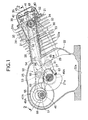
- Figs.1 and 2 show a first embodiment of the present invention wherein Fig.1 is a vertical sectional view of an engine; taken along a line 1-1 in Fig.2; and Fig.2 is a sectional view taken along a line 2-2 in Fig.1.
- Fig.3 is a sectional view similar to Fig.2, but according to a second embodiment.
- Figs. 4 and 5 show a third embodiment of the present invention wherein Fig.4 is a vertical sectional view of an engine, taken along a line 4-4 in Fig.5; and Fig.5 is a sectional view taken along a line 5-5 in Fig.4.
- A first embodiment of the present invention will now be described with reference to Figs.1 and 2. An engine according to the first embodiment is an air-cooled single-cylinder engine used, for example, in a working machine or the like, and has an
engine body 21 which comprises: acrankcase 22; acylinder block 23 slightly inclined upwards and protruding from one side of thecrankcase 22; and acylinder head 24 coupled to a head of thecylinder block 23. A large number of air-cooling fins cylinder block 23 and thecylinder head 24. Thecrankcase 22 is installed on a cylinder head of any working machine via aninstallation surface 22a of its lower face. - The
crankcase 22 comprises acase body 25 formed integrally with the cylinder block by casting to have one side opened, and a side 26 cover coupled to an end of the opened side of thecase body 25. Acrankshaft 27 integrally comprises a pair ofbalance weights crankpin 27c interconnecting both of thebalance weights case body 25 and the side cover 26. - A cylinder bore 29 slidably receiving therein a
piston 28 is formed in thecylinder block 23. Acombustion chamber 30 is formed between thecylinder block 23 and thecylinder head 24 so that a top of thepiston 28 faces thecombustion chamber 30. Anintake port 31 and anexhaust port 32 are formed in thecylinder head 24 so that they can communicate with thecombustion chamber 30. Anintake valve 33 for connecting and disconnecting theintake port 31 and thecombustion chamber 30 to and from each other as well as anexhaust valve 34 for connecting and disconnecting theexhaust port 32 and thecombustion chamber 30 to and from each other, are openably and closably disposed in thecylinder head 24. - A valve-
operating mechanism 35 for opening and closing theintake valve 33 and theexhaust valve 34 is mounted at an upper portion of theengine body 21. The valve-operating mechanism 35 comprises: acamshaft 36 rotatably driven at a reduction ratio of 1/2 from thecrankshaft 27; an intake-side cam 37 and an exhaust-side cam 38 fixed to thecamshaft 36 so as to be ratable along with thecamshaft 36; and intake-side and exhaust-side rocker arms cams side rocker arms cylinder head 24 through a common swingingsupport shaft 41 having an axis parallel to thecrankshaft 27.Tappet screws side rocker arms intake valve 33 and theexhaust valve 34, so that their advanced and retracted positions can be regulated. - The
camshaft 36 is rotatably supported in thecylinder head 24, and has an axis parallel to thecrankshaft 27. Afitting bore 44 for fitting of thecam shaft 36 is provided to open into one side of thecylinder head 24. Thus, the valve-operating mechanism 35 is covered with ahead cover 45, which is coupled to thecylinder head 24 and has alid portion 45a for closing an outer end of thefitting bore 44 so as to inhibit the detachment of thecamshaft 36 from thefitting bore 44. - A
rotary shaft 46 having an axis parallel to thecrankshaft 27 and a rotational axis above the axis of thecrankshaft 27 is rotatably supported at its opposite ends in thecase body 25 and the side cover 26 of thecrankcase 22. A rotary shaft drive means 47A is mounted between therotary shaft 46 and thecrankshaft 27, and transmits the rotational power of thecrankshaft 27 to therotary shaft 46 with rotational power reduction. On the other hand, a timing transmitting means 50 is mounted between thecamshaft 36 of the valve-operatingmechanism 35 and therotary shaft 46, and transmits the rotational power of therotary shaft 46 without rotational power reduction. Moreover, the rotary shaft drive means 47A and the timing transmitting means 50 are disposed so that they are separately disposed on axially opposite sides of thecrankpin 27c, and thecrankpin 27c is provided between the pair ofbalance weights balance weights crankshaft 27. - The rotary shaft drive means 47A comprises a
driving gear 48A fixed to thecrankshaft 27, and a drivengear 49A integrally provided on therotary shaft 46 so as to be meshed with thedriving gear 48A. Thedriving gear 48A is fixed to thecrankshaft 27 between one 27b of the pair ofbalance weights crankshaft 27 opposite from the side cover 26 and the closed end of thebody 25. The drivengear 49A is integrally formed on therotary shaft 46 in correspondence to thedriving gear 48A. - The timing transmitting means 50 is disposed between one 27a of the pair of
balance weights crankshaft 27 on the side of the side cover 26, and the side cover 26. The timing transmitting means 50 comprises: adrive sprocket 51 as a drive wheel fixed to therotary shaft 46; a drivensprocket 52 as a driven wheel mounted on thecamshaft 36; and a timingtoothed belt 53 as an endless transmitting band wound around thedrive sprocket 51 and the drivensprocket 52. Atiming belt chamber 54, in which thetiming belt 53 is allowed to travel, is formed in thecylinder block 23 and thecylinder head 24. - A
pivot shaft 55 having an axis at a position eccentric from the axis of therotary shaft 46 is integrally provided on therotary shaft 46 at a position between the pair ofbalance weights crankshaft 27. Thepivot shaft 55, thepiston 28 and thecrankshaft 27 are connected to one another through alink mechanism 58. - The
link mechanism 58 comprises: a main connectingrod 60 connected at one end to thepiston 28 through apiston pin 59; asubsidiary connecting rod 61 disposed between both thebalance weights crankshaft 27, connected to thecrankpin 27c, and connected to the other end of the main connectingrod 60; and acontrol rod 62 connected at one end to thesubsidiary connecting rod 61 at a position offset from the connected position of the main connectingrod 60, and connected at other end to thepivot shaft 55. - The
subsidiary connecting rod 61 is formed to come into sliding contact with one half of a peripheral surface of thecrankpin 27c. Acrank cap 63 mounted to come into sliding contact with the remaining half of the peripheral surface of thecrankpin 27c is fastened to thesubsidiary connecting rod 61. - The main connecting
rod 60 is turnably connected at other end to one end of thesubsidiary connecting rod 61 through afirst pin 64. Thecontrol rod 62 is turnably connected at one end to thesubsidiary connecting rod 61 through asecond pin 65, and a circular shaft bore 66 is provided in the other end of thecontrol rod 62, so that thepivot shaft 55 is relatively slidably fitted in the circular shaft bore 66. - Thus, the
rotary shaft 46 is rotatably driven at a reduction ratio of 1/2 in response to the rotation of thecrankshaft 27, and as thepivot shaft 55 is rotated about the rotational axis of therotary shaft 46, thelink mechanism 58 is operated so that the stroke of thepiston 28 at the expansion stroke is larger than that at the compression stroke, thereby performing a larger expansion task with the same amount of air-fuel mixture drawn. In this manner, a cycle heat efficiency can be enhanced. - The operation of the first embodiment will be described below. The
camshaft 36 of the valve-operatingmechanism 35 mounted at the upper portion of theengine body 21 is connected to thepivot shaft 55 through the timing transmitting means 50, and the valve-operatingmechanism 35 is constructed to be an OHC-type. Therefore, it is possible to decrease the number of parts constituting the valve-operatingmechanism 35, and to construct the valve-operatingmechanism 35 with a relatively small weight, thereby easily increasing the rotational speed. Moreover, it is possible to reduce the mechanical noise by decreasing the number of contact portions between the parts constituting the valve-operatingmechanism 35. - In addition, the
pivot shaft 55 is mounted at the position eccentric from therotary shaft 46 to which the rotational power reduced to 1/2 is transmitted from thecrankshaft 27. The timing transmitting means 50 comprises the a drivensprocket 52 mounted on thecamshaft 36, and the drivingsprocket 51 mounted on therotary shaft 46, and the timingtoothed belt 53 wound around the drivingsprocket 51 and the drivensprocket 52; and is mounted between thecamshaft 36 and therotary shaft 46 so as to transmit the rotational power reduced to 1/2 from thecrankshaft 27 to thecamshaft 36. Therefore, it is possible to downsize the drivensprocket 52 mounted on thecamshaft 36 to downsize the upper portion of theengine body 21. Moreover, only a component of an explosive force received by thecrankshaft 27 through the main connectingrod 60 and thesubsidiary connecting rod 61 is applied to therotary shaft 46 having thepivot shaft 55 provided thereon. Therefore, it is possible to set the diameter of therotary shaft 46 to be smaller than that of thecrankshaft 27, and to reduce the diameter of the drivingsprocket 51, as compared with a case where the drivingsprocket 51 is mounted on thecrankshaft 27, and correspondingly reduce the diameter of the drivensprocket 52. Thus, it is possible to compactly construct the timing transmitting means 50, thereby downsizing theengine body 21 not only in its upper portion but also its entirety, leading to an improvement in mountability to a working machine or the like. - Moreover, if the diameter of the driving
sprocket 51 is too small, the wound radius of the timingtoothed belt 53 is decreased, resulting in an increase in bending load to cause a problem in durability. However, by mounting of the drivingsprocket 51 on therotary shaft 46 where the rotational speed has been already reduced to 1/2, the diameter of the drivingsprocket 51 can be set in an appropriate range, leading to an improvement in durability of the timingtoothed belt 53. - By disposing the rotational axis of the
rotary shaft 46 above the axis of thecrankshaft 27, the distance between the drivingsprocket 51 and the drivensprocket 52 can be set to be relatively small, leading to a decrease in the length of the timingtoothed belt 53. - The rotary shaft drive means 47A for transmitting the rotational power from the
crankshaft 27 to therotary shaft 46 at a reduction ratio of 1/2 and the timing transmitting means 50, are separately disposed on the axially opposite sides of thecrankpin 27c, respectively, so that the component of the explosive force received by thecrankshaft 27 is applied to a substantially central portion of therotary shaft 46. Therefore, the distances between the bearings at opposite ends of thecrankshaft 27 and therotary shaft 46 can be set to be substantially equal, thereby improving durability of therotary shaft 46, and shaft loads applied to the opposite ends of therotary shaft 46 can be substantially equalized, thereby downsizing support portions at the opposite ends of therotary shaft 46 can be reduced. - In addition, the driving
sprocket 51 of the timing transmitting means 50 required to be matched in timing is mounted on therotary shaft 46 between the side cover 26 and one 27a of the pair ofbalance weights crankshaft 27 on the side of the side cover 26. Therefore, it is possible to facilitate the visual checking on a timing mark and to enhance the assemblability. - Moreover, because the
crankshaft 27 includes the pair ofbalance weights subsidiary connecting rod 61, the balance of the force applied to thecrankshaft 27 can be excellent. - Fig.3 shows a second embodiment of the present invention, wherein portions and components corresponding to those in the first embodiment are designated by the same reference numerals, and merely shown, and the detailed description of them is omitted.
- A rotary shaft drive means 47B for transmitting the rotational power from a
crankshaft 27 to a rotary shaft 46' at a reduction ratio of 1/2 comprises adriving gear 48B fixed to thecrankshaft 27, and a drivengear 49B integrally provided in the rotary shaft 46' so that it is meshed with thedriving gear 48B. Thedriving gear 48B is fixed to thecrankshaft 27 between acrankpin 27c of thecrankshaft 27 and a side cover 26, and opposite ends of thecrankpin 27c interconnect a pair ofbalance weights 27a and 28b. Therefore, thedriving gear 48B is fixed to thecrankshaft 27 between theside cover 27 and one 27a of thebalance weights 27a and 28b on the side of the side cover 26. - Moreover, a timing transmitting means 50 is mounted between the
camshaft 36 of the valve-operatingmechanism 35 and the rotary shaft 46' , and disposed between theside cover 27 and one 27a of thebalance weights 27a and 28b on the side of the side cover 26. The timing transmitting means 50 comprises a drivingsprocket 51 fixed to the rotary shaft 46', a drivensprocket 52 mounted on thecamshaft 36, and atiming belt 53 wound around the drivingsprocket 51 and the drivensprocket 52. - Namely, the rotary shaft drive means 47B and the timing transmitting means 50 are disposed between the
balance weight 27a connected to one end of thecrankpin 27c and the side cover 26, but the timing transmitting means 50 is disposed at a position closer to the side cover 26 than the rotary shaft drive means 47B. - According to the second embodiment, the driving
sprocket 51 of the timing transmitting means 50 required to be matched in timing can be mounted on the side of the side cover 26, thereby facilitating the visual checking on a timing mark, and also facilitating the assembling of the rotary shaft drive means 47B to improve the assemblability. - A third embodiment of the present invention will now be described with reference to Figs.4 and 5. An engine is an air-cooled single-cylinder engine used, for example, in a working machine or the like, and has an
engine body 71 which comprises: acrankcase 72; acylinder block 73 slightly inclined upwards and protruding from one side of thecrankcase 72; acylinder head 74 coupled to a head of thecylinder block 23; and ahead cover 75 coupled to thecylinder head 74. Thecrankcase 72 is installed on a cylinder head of any working machine via aninstallation surface 72a of its lower face. - A
crankshaft 77 is rotatably supported in acrankcase 72, and integrally provided with a pair ofbalance weights crankpin 77c interconnecting both thebalance weights - A cylinder bore 79 slidably receiving therein a
piston 78 is formed in thecylinder block 73. Acombustion chamber 80 is formed between thecylinder block 73 and thecylinder head 74 so that a top of thepiston 78 faces thecombustion chamber 80. Anintake port 81 and anexhaust port 82 are formed in thecylinder head 24 so that they can communicate with thecombustion chamber 80. Anintake valve 83 for connecting and disconnecting theintake port 81 and thecombustion chamber 80 to and from each other as well as anexhaust valve 84 for connecting and disconnecting theexhaust port 82 and thecombustion chamber 80 to and from each other, are openably and closably disposed in thecylinder head 24. - A valve-operating
mechanism 85 for opening and closing theintake valve 83 and theexhaust valve 84 includes: acamshaft 86 rotatably driven at a reduction ratio of 1/2 from thecrankshaft 27; an intake-side cam 87 and an exhaust-side cam 88 provided on thecamshaft 36; an intake-side rocker arm 89 swung following the intake-side cam 87; and an exhaust-side rocker arm (not shown) swung following the exhaust-side cam 88. Each of the intake-side and exhaust-side rocker arms cylinder head 74 through a common swinging support shaft 91 having an axis parallel to thecrankshaft 27. Atappet screw 92 is threadedly engaged with the other end of the intake-side rocker arm intake valve 83, so that it is advanced and retracted positions can be regulated. A tappet screw (not shown) is threadedly engaged with the other end of the exhaust-side rocker arm to abut against an upper end of theexhaust valve 84, so that its advanced and retracted positions can be regulated. - The
camshaft 86 is rotatably supported between thecylinder head 74 and thehead cover 75, and has an axis parallel to thecrankshaft 77. A timing transmitting means 95 is mounted between thecamshaft 86 and thecrankshaft 77, and disposed between one 77a of the pair ofbalance weights crankshaft 77 andcrankcase 72. The timing transmitting means 95 comprises a drivingsprocket 96 fixed to therotary shaft 77, a drivensprocket 97 mounted on thecamshaft 86, and atiming belt 98 wound around the drivingsprocket 96 and the drivensprocket 97. Abelt chamber 99, in which thetiming belt 53 is allowed to travel, is formed in thecylinder block 73 and thecylinder head 74. - A
pivot shaft 100 having an axis eccentric from the rotational axis of thecamshaft 86 is integrally provided on thecamshaft 86 between the intake-side cam 87 and the exhaust-side cam 88. Thepivot shaft 100, thepiston 78 and thecrankshaft 77 are connected to one another through alink mechanism 101. - The
link mechanism 101 comprises: a main connectingrod 102 connected at one end to thepiston 78 through apiston pin 105; asubsidiary connecting rod 103 connected to thecrankpin 77c of thecrankshaft 77 and connected to the other end of the main connectingrod 102; and acontrol rod 104 connected at one end to thesubsidiary connecting rod 103 at a position offset from the connected position of the main connectingrod 102, and connected at other end to thepivot shaft 100. - The
subsidiary connecting rod 103 is formed to come into sliding contact with one half of a peripheral surface of thecrankpin 77c. Acrank cap 106 mounted to come into sliding contact with the remaining half of the peripheral surface of thecrankpin 77c is fastened to thesubsidiary connecting rod 103. - The main connecting
rod 102 is turnably connected at other end to one end of thesubsidiary connecting rod 103 through afirst pin 107. Thecontrol rod 104 is turnably connected at one end to thesubsidiary connecting rod 103 through asecond pin 108. A circular shaft bore 109 is provided in the other end of thecontrol rod 104, so that thepivot shaft 100 is relatively slidably fitted in thecircular shaft bore 109. - Moreover, centerlines of the main connecting
rod 102 and thecontrol rod 104 are disposed in the same plane perpendicular to the axis of thecrankshaft 77. Thecontrol rod 104 extends vertically through anoperating chamber 110 provided in thecylinder block 73 adjacent to the cylinder bore 79. - Thus, as the
pivot shaft 100 is rotated at a reduction ratio of 1/2 in response to the rotation of thecrankshaft 77, thelink mechanism 101 is operated so that the stroke of thepiston 78 at the expansion stroke is larger than that at the compression stroke, thereby performing a larger expansion task with the same amount of air-fuel mixture drawn. In this manner, a cycle heat efficiency can be enhanced. - The operation of the third embodiment will be describedbelow. The timing transmitting means 95 for transmitting the rotational power of the
crankshaft 77 at a reduction ratio of 1/2 is mounted between thecamshaft 86 of the valve-operatingmechanism 85 mounted at the upper portion of theengine body 21 and thecrankshaft 77. Thepivot shaft 100 having the axis eccentric from the rotational axis of thecamshaft 86 is provided on thecamshaft 86, and thecontrol rod 104 constituting a portion of thelink mechanism 101 is connected to thepivot shaft 100. - Namely, the valve-operating
mechanism 85 is constructed to be an OHC-type, and hence it is possible to decrease the number of parts constituting the valve-operatingmechanism 85 and to construct the valve-operatingmechanism 85 at a relatively small weight, thereby easily increasing the rotational speed. Moreover, it is possible to reduce the mechanical noise by decreasing the number of contact portions between the parts constituting the valve-operatingmechanism 85. - In addition, the rotational power reduced by the timing transmitting means 95 at a reduction ratio of 1/2 is transmitted from the
crankshaft 77 to thecamshaft 86 of the valve-operatingmechanism 85. Because thepivot shaft 100 is provided on thecamshaft 86, it is unnecessary to secure a space for disposition of the rotary shaft, as compared with a case where the rotary shaft having the pivot shaft is rotatably supported in the crankcase. In this manner, it is possible to compactly construct thecrankcase 72 and to set the height of the engine to be lower. Moreover, it is unnecessary to provide a reducing drive mechanism for driving the rotary shaft between the rotary shaft and the crankshaft, and hence it is possible to reduce the length of thecrankshaft 77 to compactly construct the entire engine. It is also possible to reduce the number of parts by eliminating the need of the rotary shaft. - Further, the
control rod 104 is formed between the lower and upper portions of theengine body 71 to have a relatively large length, but it is possible to suppress the wearing by reducing deflection amount of thecontrol rod 104 at a point of connection to thesubsidiary connecting rod 103. Moreover, thecontrol rod 104 having a weight increased due to the relatively large length performs a counter weight function, and thus it is possible to improve the dynamic balance of thecrankshaft 77. - Additionally, because the centerlines of the main connecting
rod 102 and thecontrol rod 104 are disposed on the same plane, the main connectingrod 102, thesubsidiary connecting rod 103 and thecontrol rod 104 can be disposed compactly in a direction along the axis of thecrankshaft 77, leading to a reduction in distance between the bearings at the opposite ends of thecrankshaft 77. Further, a load on the main connectingrod 102 and thesubsidiary connecting rod 103 due to the explosive force can be decreased by the displacement of thecontrol rod 104 toward thecrankshaft 77. - Although the embodiments of the present invention have been described in detail, the present invention is not limited to the above-described embodiments, and various modifications in design may be made without departing from the scope of the invention defined in claims.
- A stroke-variable engine includes a pivot shaft which is rotatably supported in a crankcase so as to be rotatable about an eccentric axis parallel to a crankshaft and which is connected to a control rod so that a rotational power reduced at a reduction ratio of 1/2 is transmitted from the crankshaft to the pivot shaft. A camshaft of a valve-operating mechanism mounted at an upper portion of an engine body and the pivot shaft are operatively connected to each other. Thus, it is possible to decrease the number of parts of the valve-operating mechanism, increase a rotational speed, and further reduce mechanical noise.
Claims (7)
- A stroke-variable engine comprising:a main connecting rod connected at one end to a piston through a piston pin;a subsidiary connecting rod which is connected to a crankpin of a crankshaft rotatably supported in a crankcase of an engine body and which is connected to the other end of the main connecting rod;a control rod connected at one end to the subsidiary connecting rod at a position offset from a connected position of the main connecting rod; anda pivot shaft which is rotatably supported in the crankcase so as to be rotatable about an eccentric axis parallel to the crankshaft and which is connected to the other end of the control rod so that a rotational power reduced at a reduction ratio of 1/2 is transmitted from the crankshaft to the pivot shaft,wherein a camshaft of a valve-operating mechanism mounted at an upper portion of the engine body and the pivot shaft are operatively connected to each other.
- A stroke-variable engine according to claim 1, wherein the pivot shaft is provided at an eccentric position on a rotary shaft which is rotatably supported in the crankcase so as to be rotatable about the eccentric axis as a rotational axis and to which the rotational power reduced at a reduction ratio of 1/2 is transmitted from the crankshaft; and a timing transmitting means is mounted between the camshaft and the rotary shaft, and comprises a driven wheel mounted on the camshaft, a drive wheel mounted on the rotary shaft, and an endless power transmitting belt wound around the drive wheel and the driven wheel.
- A stroke-variable engine according to claim 2, wherein a rotary shaft drive means for transmitting the rotational power from the crankshaft to the rotary shaft at a reduction ratio of 1/2 and the timing transmitting means are separately disposed on axially opposite sides of the crankpin.
- A stroke-variable engine according to claim 2, wherein the crankcase comprises a case body with its one side opened, and a side cover coupled to an end of the opened side of the case body; and a rotary shaft drive means for transmitting the rotational power from the crankshaft to the rotary shaft at a reduction ratio of 1/2 and the timing transmitting means are disposed between the crankpin and the side cover, the timing transmitting means being disposed on the side of the side cover.
- A stroke-variable engine according to any of claims 2 to 4, wherein the crankshaft includes a pair of balance weights which sandwich the subsidiary connecting rod from opposite sides.
- A stroke-variable engine according to claim 1, wherein a timing transmitting means for transmitting the rotational power of the crankshaft at a reduction ratio of 1/2 is mounted between the camshaft of the valve-operating mechanism mounted at an upper portion of the engine body and the crankshaft; and the pivot shaft having an axis eccentric from the rotational axis of the camshaft is provided on the camshaft.
- A stroke-variable engine according to claim 6, wherein centerlines of the main connecting rod and the control rod are disposed on the same plane.
Applications Claiming Priority (2)
| Application Number | Priority Date | Filing Date | Title |
|---|---|---|---|
| JP2005247795A JP4459135B2 (en) | 2005-08-29 | 2005-08-29 | Variable stroke engine |
| JP2005247794A JP2007064011A (en) | 2005-08-29 | 2005-08-29 | Stroke variable engine |
Publications (3)
| Publication Number | Publication Date |
|---|---|
| EP1760290A2 true EP1760290A2 (en) | 2007-03-07 |
| EP1760290A3 EP1760290A3 (en) | 2012-02-29 |
| EP1760290B1 EP1760290B1 (en) | 2017-07-05 |
Family
ID=37460431
Family Applications (1)
| Application Number | Title | Priority Date | Filing Date |
|---|---|---|---|
| EP06017178.2A Not-in-force EP1760290B1 (en) | 2005-08-29 | 2006-08-17 | Variable stroke engine |
Country Status (9)
| Country | Link |
|---|---|
| US (1) | US7305938B2 (en) |
| EP (1) | EP1760290B1 (en) |
| KR (1) | KR100801520B1 (en) |
| AU (1) | AU2006203584B2 (en) |
| BR (1) | BRPI0603470A (en) |
| CA (1) | CA2556462C (en) |
| ES (1) | ES2633617T3 (en) |
| MX (1) | MXPA06009491A (en) |
| TW (1) | TWI308614B (en) |
Cited By (5)
| Publication number | Priority date | Publication date | Assignee | Title |
|---|---|---|---|---|
| WO2011098104A1 (en) | 2010-01-14 | 2011-08-18 | Audi Ag | Internal combustion engine having an extended expansion stroke and counterweights on the eccentric shaft |
| DE102010027351A1 (en) | 2010-07-16 | 2012-01-19 | Audi Ag | Internal-combustion engine has crankshaft and eccentric shaft that are provide d for extension of expansion stroke from pistons of internal-combustion engine by piston rods and coupling element is connected with crankshaft |
| DE102010032441A1 (en) | 2010-07-28 | 2012-02-02 | Audi Ag | Internal combustion engine with multi-joint crank drive and additional masses at Anlenkpleueln the multi-joint crank drive for the eradication of free inertial forces |
| FR3021071A1 (en) * | 2014-05-19 | 2015-11-20 | IFP Energies Nouvelles | INTERNAL COMBUSTION ENGINE WITH A PROLONGED RELAXATION PHASE, IN PARTICULAR FOR MOTOR VEHICLES. |
| US11117449B2 (en) | 2016-09-16 | 2021-09-14 | Carrier Corporation | Fuel system control for refrigeration unit engine |
Families Citing this family (3)
| Publication number | Priority date | Publication date | Assignee | Title |
|---|---|---|---|---|
| CN103195566B (en) * | 2013-04-03 | 2015-01-21 | 浙江大学 | Combustion engine capable of changing displacement continuously |
| US11598256B2 (en) | 2021-01-12 | 2023-03-07 | Robert P Hogan | Throttle-at-valve apparatus |
| US11408336B2 (en) | 2021-01-12 | 2022-08-09 | Robert P. Hogan | All-stroke-variable internal combustion engine |
Citations (3)
| Publication number | Priority date | Publication date | Assignee | Title |
|---|---|---|---|---|
| FR1109466A (en) * | 1953-07-24 | 1956-01-30 | Improvements to four-stroke internal combustion engines | |
| JP2003013764A (en) * | 2001-07-02 | 2003-01-15 | Nissan Motor Co Ltd | Piston-crank device for internal combustion engine |
| JP2003083101A (en) * | 2001-06-27 | 2003-03-19 | Honda Motor Co Ltd | Internal combustion engine |
Family Cites Families (10)
| Publication number | Priority date | Publication date | Assignee | Title |
|---|---|---|---|---|
| US4448166A (en) * | 1980-11-28 | 1984-05-15 | Yanmar Diesel Engine Co., Ltd. | Overhead cam type diesel engine |
| US4517931A (en) * | 1983-06-30 | 1985-05-21 | Nelson Carl D | Variable stroke engine |
| DE29614589U1 (en) * | 1996-08-22 | 1997-12-18 | Fev Motorentech Gmbh & Co Kg | Reciprocating machine with adjustable mass balance |
| JP3488585B2 (en) | 1996-12-19 | 2004-01-19 | トヨタ自動車株式会社 | Valve train for internal combustion engine |
| GB2364745A (en) * | 2000-07-14 | 2002-02-06 | Jonathan Austin Ma | Camshaft drive system for selectable two-stroke/ four-stroke i.c. engine |
| JP2003314211A (en) | 2002-04-17 | 2003-11-06 | Honda Motor Co Ltd | Stroke varying engine |
| JP2003314237A (en) | 2002-04-17 | 2003-11-06 | Honda Motor Co Ltd | Engine |
| US7210446B2 (en) * | 2003-01-27 | 2007-05-01 | Tihomir Sic | V-twin configuration having rotary mechanical field assembly |
| JP2007064013A (en) * | 2005-08-29 | 2007-03-15 | Honda Motor Co Ltd | Stroke variable engine |
| DE102006003737B3 (en) * | 2006-01-24 | 2007-06-06 | Iav Gmbh Ingenieurgesellschaft Auto Und Verkehr | Reciprocating-piston combustion engine, has piston connected to pulling and pressing rod guided parallel to cylinder axis and pulling and pressing rod interacts with transmission lever along extended channel |
-
2006
- 2006-08-14 TW TW095129787A patent/TWI308614B/en not_active IP Right Cessation
- 2006-08-15 AU AU2006203584A patent/AU2006203584B2/en not_active Ceased
- 2006-08-17 EP EP06017178.2A patent/EP1760290B1/en not_active Not-in-force
- 2006-08-17 ES ES06017178.2T patent/ES2633617T3/en active Active
- 2006-08-21 CA CA002556462A patent/CA2556462C/en not_active Expired - Fee Related
- 2006-08-21 MX MXPA06009491A patent/MXPA06009491A/en active IP Right Grant
- 2006-08-22 US US11/507,662 patent/US7305938B2/en not_active Expired - Fee Related
- 2006-08-28 KR KR1020060081702A patent/KR100801520B1/en not_active IP Right Cessation
- 2006-08-28 BR BRPI0603470-5A patent/BRPI0603470A/en active Search and Examination
Patent Citations (3)
| Publication number | Priority date | Publication date | Assignee | Title |
|---|---|---|---|---|
| FR1109466A (en) * | 1953-07-24 | 1956-01-30 | Improvements to four-stroke internal combustion engines | |
| JP2003083101A (en) * | 2001-06-27 | 2003-03-19 | Honda Motor Co Ltd | Internal combustion engine |
| JP2003013764A (en) * | 2001-07-02 | 2003-01-15 | Nissan Motor Co Ltd | Piston-crank device for internal combustion engine |
Cited By (10)
| Publication number | Priority date | Publication date | Assignee | Title |
|---|---|---|---|---|
| WO2011098104A1 (en) | 2010-01-14 | 2011-08-18 | Audi Ag | Internal combustion engine having an extended expansion stroke and counterweights on the eccentric shaft |
| DE102010004588A1 (en) | 2010-01-15 | 2011-09-01 | Audi Ag | Internal combustion engine with extended expansion stroke and balance weights on the eccentric shaft |
| DE102010004588B4 (en) * | 2010-01-15 | 2015-12-24 | Audi Ag | Internal combustion engine with extended expansion stroke and balance weights on the eccentric shaft |
| DE102010027351A1 (en) | 2010-07-16 | 2012-01-19 | Audi Ag | Internal-combustion engine has crankshaft and eccentric shaft that are provide d for extension of expansion stroke from pistons of internal-combustion engine by piston rods and coupling element is connected with crankshaft |
| DE102010027351B4 (en) * | 2010-07-16 | 2013-06-13 | Audi Ag | Internal combustion engine with extended expansion stroke and torque compensation |
| DE102010032441A1 (en) | 2010-07-28 | 2012-02-02 | Audi Ag | Internal combustion engine with multi-joint crank drive and additional masses at Anlenkpleueln the multi-joint crank drive for the eradication of free inertial forces |
| WO2012013298A2 (en) | 2010-07-28 | 2012-02-02 | Audi Ag | Internal combustion engine having a multi-joint crank drive and additional masses on articulated connecting rods of the multi-joint crank drive for damping free mass forces |
| US8978616B2 (en) | 2010-07-28 | 2015-03-17 | Audi Ag | Internal combustion engine with multi-joint crank drive and additional masses on articulated connecting rods of the multi-joint crank drive for damping free inertia forces |
| FR3021071A1 (en) * | 2014-05-19 | 2015-11-20 | IFP Energies Nouvelles | INTERNAL COMBUSTION ENGINE WITH A PROLONGED RELAXATION PHASE, IN PARTICULAR FOR MOTOR VEHICLES. |
| US11117449B2 (en) | 2016-09-16 | 2021-09-14 | Carrier Corporation | Fuel system control for refrigeration unit engine |
Also Published As
| Publication number | Publication date |
|---|---|
| AU2006203584A1 (en) | 2007-03-15 |
| CA2556462C (en) | 2009-10-06 |
| ES2633617T3 (en) | 2017-09-22 |
| KR100801520B1 (en) | 2008-02-12 |
| TWI308614B (en) | 2009-04-11 |
| TW200712317A (en) | 2007-04-01 |
| MXPA06009491A (en) | 2007-02-27 |
| US7305938B2 (en) | 2007-12-11 |
| KR20070026065A (en) | 2007-03-08 |
| EP1760290B1 (en) | 2017-07-05 |
| US20070125326A1 (en) | 2007-06-07 |
| AU2006203584B2 (en) | 2009-04-23 |
| EP1760290A3 (en) | 2012-02-29 |
| BRPI0603470A (en) | 2007-04-27 |
| CA2556462A1 (en) | 2007-02-28 |
Similar Documents
| Publication | Publication Date | Title |
|---|---|---|
| EP1760290B1 (en) | Variable stroke engine | |
| EP2048335B1 (en) | Variable stroke engine | |
| US8166930B2 (en) | Variable compression ratio apparatus | |
| US8555829B2 (en) | Variable compression ratio apparatus | |
| EP1347159B1 (en) | Engine | |
| AU2003201333B2 (en) | Engine with Variable Compression Ratio | |
| EP2048336B1 (en) | Variable stroke engine | |
| JP2007064011A (en) | Stroke variable engine | |
| CA2303736C (en) | Overhead ring cam engine with angled split housing | |
| EP2021584B1 (en) | Internal combustion engine | |
| EP2655814A2 (en) | Anti-rotation roller valve lifter | |
| EP1985812B1 (en) | V-type engine | |
| US7506627B2 (en) | Balancer shaft arrangement for engine | |
| JP4025622B2 (en) | General-purpose single cylinder engine | |
| CA2300784C (en) | External drive double shaft overhead cam engine (dsohc) | |
| US6953015B2 (en) | Engine | |
| JP2008138607A (en) | Stroke characteristic variable engine | |
| JP4459135B2 (en) | Variable stroke engine | |
| JP2528728Y2 (en) | Valve drive mechanism of portable work machine engine | |
| JP2003020953A (en) | Internal combustion engine | |
| JP3360008B2 (en) | Valve systems for portable engines | |
| JPH07293268A (en) | Engine output taking-out device |
Legal Events
| Date | Code | Title | Description |
|---|---|---|---|
| PUAI | Public reference made under article 153(3) epc to a published international application that has entered the european phase |
Free format text: ORIGINAL CODE: 0009012 |
|
| AK | Designated contracting states |
Kind code of ref document: A2 Designated state(s): AT BE BG CH CY CZ DE DK EE ES FI FR GB GR HU IE IS IT LI LT LU LV MC NL PL PT RO SE SI SK TR |
|
| AX | Request for extension of the european patent |
Extension state: AL BA HR MK YU |
|
| PUAL | Search report despatched |
Free format text: ORIGINAL CODE: 0009013 |
|
| AK | Designated contracting states |
Kind code of ref document: A3 Designated state(s): AT BE BG CH CY CZ DE DK EE ES FI FR GB GR HU IE IS IT LI LT LU LV MC NL PL PT RO SE SI SK TR |
|
| AX | Request for extension of the european patent |
Extension state: AL BA HR MK RS |
|
| RIC1 | Information provided on ipc code assigned before grant |
Ipc: F02B 41/04 20060101ALI20120120BHEP Ipc: F02B 75/04 20060101AFI20120120BHEP |
|
| 17P | Request for examination filed |
Effective date: 20120820 |
|
| AKX | Designation fees paid |
Designated state(s): AT BE BG CH CY CZ DE DK EE ES FI FR GB GR HU IE IS IT LI LT LU LV MC NL PL PT RO SE SI SK TR |
|
| GRAP | Despatch of communication of intention to grant a patent |
Free format text: ORIGINAL CODE: EPIDOSNIGR1 |
|
| INTG | Intention to grant announced |
Effective date: 20170125 |
|
| GRAS | Grant fee paid |
Free format text: ORIGINAL CODE: EPIDOSNIGR3 |
|
| GRAA | (expected) grant |
Free format text: ORIGINAL CODE: 0009210 |
|
| AK | Designated contracting states |
Kind code of ref document: B1 Designated state(s): AT BE BG CH CY CZ DE DK EE ES FI FR GB GR HU IE IS IT LI LT LU LV MC NL PL PT RO SE SI SK TR |
|
| REG | Reference to a national code |
Ref country code: GB Ref legal event code: FG4D |
|
| REG | Reference to a national code |
Ref country code: CH Ref legal event code: EP |
|
| REG | Reference to a national code |
Ref country code: AT Ref legal event code: REF Ref document number: 906779 Country of ref document: AT Kind code of ref document: T Effective date: 20170715 |
|
| REG | Reference to a national code |
Ref country code: IE Ref legal event code: FG4D |
|
| REG | Reference to a national code |
Ref country code: FR Ref legal event code: PLFP Year of fee payment: 12 |
|
| REG | Reference to a national code |
Ref country code: DE Ref legal event code: R096 Ref document number: 602006052942 Country of ref document: DE |
|
| REG | Reference to a national code |
Ref country code: ES Ref legal event code: FG2A Ref document number: 2633617 Country of ref document: ES Kind code of ref document: T3 Effective date: 20170922 |
|
| REG | Reference to a national code |
Ref country code: NL Ref legal event code: FP |
|
| PGFP | Annual fee paid to national office [announced via postgrant information from national office to epo] |
Ref country code: NL Payment date: 20170814 Year of fee payment: 12 |
|
| PGFP | Annual fee paid to national office [announced via postgrant information from national office to epo] |
Ref country code: GB Payment date: 20170816 Year of fee payment: 12 Ref country code: ES Payment date: 20170901 Year of fee payment: 12 Ref country code: DE Payment date: 20170808 Year of fee payment: 12 Ref country code: FR Payment date: 20170728 Year of fee payment: 12 |
|
| REG | Reference to a national code |
Ref country code: AT Ref legal event code: MK05 Ref document number: 906779 Country of ref document: AT Kind code of ref document: T Effective date: 20170705 |
|
| REG | Reference to a national code |
Ref country code: LT Ref legal event code: MG4D |
|
| PGFP | Annual fee paid to national office [announced via postgrant information from national office to epo] |
Ref country code: BE Payment date: 20170724 Year of fee payment: 12 |
|
| PG25 | Lapsed in a contracting state [announced via postgrant information from national office to epo] |
Ref country code: SE Free format text: LAPSE BECAUSE OF FAILURE TO SUBMIT A TRANSLATION OF THE DESCRIPTION OR TO PAY THE FEE WITHIN THE PRESCRIBED TIME-LIMIT Effective date: 20170705 Ref country code: AT Free format text: LAPSE BECAUSE OF FAILURE TO SUBMIT A TRANSLATION OF THE DESCRIPTION OR TO PAY THE FEE WITHIN THE PRESCRIBED TIME-LIMIT Effective date: 20170705 Ref country code: FI Free format text: LAPSE BECAUSE OF FAILURE TO SUBMIT A TRANSLATION OF THE DESCRIPTION OR TO PAY THE FEE WITHIN THE PRESCRIBED TIME-LIMIT Effective date: 20170705 Ref country code: LT Free format text: LAPSE BECAUSE OF FAILURE TO SUBMIT A TRANSLATION OF THE DESCRIPTION OR TO PAY THE FEE WITHIN THE PRESCRIBED TIME-LIMIT Effective date: 20170705 |
|
| PG25 | Lapsed in a contracting state [announced via postgrant information from national office to epo] |
Ref country code: GR Free format text: LAPSE BECAUSE OF FAILURE TO SUBMIT A TRANSLATION OF THE DESCRIPTION OR TO PAY THE FEE WITHIN THE PRESCRIBED TIME-LIMIT Effective date: 20171006 Ref country code: LV Free format text: LAPSE BECAUSE OF FAILURE TO SUBMIT A TRANSLATION OF THE DESCRIPTION OR TO PAY THE FEE WITHIN THE PRESCRIBED TIME-LIMIT Effective date: 20170705 Ref country code: IS Free format text: LAPSE BECAUSE OF FAILURE TO SUBMIT A TRANSLATION OF THE DESCRIPTION OR TO PAY THE FEE WITHIN THE PRESCRIBED TIME-LIMIT Effective date: 20171105 Ref country code: PL Free format text: LAPSE BECAUSE OF FAILURE TO SUBMIT A TRANSLATION OF THE DESCRIPTION OR TO PAY THE FEE WITHIN THE PRESCRIBED TIME-LIMIT Effective date: 20170705 Ref country code: BG Free format text: LAPSE BECAUSE OF FAILURE TO SUBMIT A TRANSLATION OF THE DESCRIPTION OR TO PAY THE FEE WITHIN THE PRESCRIBED TIME-LIMIT Effective date: 20171005 |
|
| REG | Reference to a national code |
Ref country code: CH Ref legal event code: PL |
|
| REG | Reference to a national code |
Ref country code: DE Ref legal event code: R097 Ref document number: 602006052942 Country of ref document: DE |
|
| PG25 | Lapsed in a contracting state [announced via postgrant information from national office to epo] |
Ref country code: CH Free format text: LAPSE BECAUSE OF NON-PAYMENT OF DUE FEES Effective date: 20170831 Ref country code: MC Free format text: LAPSE BECAUSE OF FAILURE TO SUBMIT A TRANSLATION OF THE DESCRIPTION OR TO PAY THE FEE WITHIN THE PRESCRIBED TIME-LIMIT Effective date: 20170705 Ref country code: RO Free format text: LAPSE BECAUSE OF FAILURE TO SUBMIT A TRANSLATION OF THE DESCRIPTION OR TO PAY THE FEE WITHIN THE PRESCRIBED TIME-LIMIT Effective date: 20170705 Ref country code: LI Free format text: LAPSE BECAUSE OF NON-PAYMENT OF DUE FEES Effective date: 20170831 Ref country code: CZ Free format text: LAPSE BECAUSE OF FAILURE TO SUBMIT A TRANSLATION OF THE DESCRIPTION OR TO PAY THE FEE WITHIN THE PRESCRIBED TIME-LIMIT Effective date: 20170705 Ref country code: DK Free format text: LAPSE BECAUSE OF FAILURE TO SUBMIT A TRANSLATION OF THE DESCRIPTION OR TO PAY THE FEE WITHIN THE PRESCRIBED TIME-LIMIT Effective date: 20170705 |
|
| PLBE | No opposition filed within time limit |
Free format text: ORIGINAL CODE: 0009261 |
|
| STAA | Information on the status of an ep patent application or granted ep patent |
Free format text: STATUS: NO OPPOSITION FILED WITHIN TIME LIMIT |
|
| REG | Reference to a national code |
Ref country code: IE Ref legal event code: MM4A |
|
| PG25 | Lapsed in a contracting state [announced via postgrant information from national office to epo] |
Ref country code: SK Free format text: LAPSE BECAUSE OF FAILURE TO SUBMIT A TRANSLATION OF THE DESCRIPTION OR TO PAY THE FEE WITHIN THE PRESCRIBED TIME-LIMIT Effective date: 20170705 Ref country code: EE Free format text: LAPSE BECAUSE OF FAILURE TO SUBMIT A TRANSLATION OF THE DESCRIPTION OR TO PAY THE FEE WITHIN THE PRESCRIBED TIME-LIMIT Effective date: 20170705 |
|
| 26N | No opposition filed |
Effective date: 20180406 |
|
| PG25 | Lapsed in a contracting state [announced via postgrant information from national office to epo] |
Ref country code: LU Free format text: LAPSE BECAUSE OF NON-PAYMENT OF DUE FEES Effective date: 20170817 |
|
| PG25 | Lapsed in a contracting state [announced via postgrant information from national office to epo] |
Ref country code: IE Free format text: LAPSE BECAUSE OF NON-PAYMENT OF DUE FEES Effective date: 20170817 |
|
| PG25 | Lapsed in a contracting state [announced via postgrant information from national office to epo] |
Ref country code: SI Free format text: LAPSE BECAUSE OF FAILURE TO SUBMIT A TRANSLATION OF THE DESCRIPTION OR TO PAY THE FEE WITHIN THE PRESCRIBED TIME-LIMIT Effective date: 20170705 |
|
| PGFP | Annual fee paid to national office [announced via postgrant information from national office to epo] |
Ref country code: IT Payment date: 20180426 Year of fee payment: 12 |
|
| REG | Reference to a national code |
Ref country code: DE Ref legal event code: R119 Ref document number: 602006052942 Country of ref document: DE |
|
| REG | Reference to a national code |
Ref country code: NL Ref legal event code: MM Effective date: 20180901 |
|
| GBPC | Gb: european patent ceased through non-payment of renewal fee |
Effective date: 20180817 |
|
| REG | Reference to a national code |
Ref country code: BE Ref legal event code: MM Effective date: 20180831 |
|
| PG25 | Lapsed in a contracting state [announced via postgrant information from national office to epo] |
Ref country code: NL Free format text: LAPSE BECAUSE OF NON-PAYMENT OF DUE FEES Effective date: 20180901 Ref country code: HU Free format text: LAPSE BECAUSE OF FAILURE TO SUBMIT A TRANSLATION OF THE DESCRIPTION OR TO PAY THE FEE WITHIN THE PRESCRIBED TIME-LIMIT; INVALID AB INITIO Effective date: 20060817 |
|
| PG25 | Lapsed in a contracting state [announced via postgrant information from national office to epo] |
Ref country code: DE Free format text: LAPSE BECAUSE OF NON-PAYMENT OF DUE FEES Effective date: 20190301 Ref country code: IT Free format text: LAPSE BECAUSE OF NON-PAYMENT OF DUE FEES Effective date: 20180817 |
|
| PG25 | Lapsed in a contracting state [announced via postgrant information from national office to epo] |
Ref country code: FR Free format text: LAPSE BECAUSE OF NON-PAYMENT OF DUE FEES Effective date: 20180831 Ref country code: BE Free format text: LAPSE BECAUSE OF NON-PAYMENT OF DUE FEES Effective date: 20180831 |
|
| REG | Reference to a national code |
Ref country code: ES Ref legal event code: FD2A Effective date: 20190918 |
|
| PG25 | Lapsed in a contracting state [announced via postgrant information from national office to epo] |
Ref country code: CY Free format text: LAPSE BECAUSE OF NON-PAYMENT OF DUE FEES Effective date: 20170705 Ref country code: GB Free format text: LAPSE BECAUSE OF NON-PAYMENT OF DUE FEES Effective date: 20180817 Ref country code: ES Free format text: LAPSE BECAUSE OF NON-PAYMENT OF DUE FEES Effective date: 20180818 |
|
| PG25 | Lapsed in a contracting state [announced via postgrant information from national office to epo] |
Ref country code: TR Free format text: LAPSE BECAUSE OF FAILURE TO SUBMIT A TRANSLATION OF THE DESCRIPTION OR TO PAY THE FEE WITHIN THE PRESCRIBED TIME-LIMIT Effective date: 20170705 |
|
| PG25 | Lapsed in a contracting state [announced via postgrant information from national office to epo] |
Ref country code: PT Free format text: LAPSE BECAUSE OF FAILURE TO SUBMIT A TRANSLATION OF THE DESCRIPTION OR TO PAY THE FEE WITHIN THE PRESCRIBED TIME-LIMIT Effective date: 20170705 |