EP1759722A1 - Beschichtung von Teilen aus Titan oder einer Titan-Legierung zur Verhinderung von Kaltverschweissung - Google Patents
Beschichtung von Teilen aus Titan oder einer Titan-Legierung zur Verhinderung von Kaltverschweissung Download PDFInfo
- Publication number
- EP1759722A1 EP1759722A1 EP20050019053 EP05019053A EP1759722A1 EP 1759722 A1 EP1759722 A1 EP 1759722A1 EP 20050019053 EP20050019053 EP 20050019053 EP 05019053 A EP05019053 A EP 05019053A EP 1759722 A1 EP1759722 A1 EP 1759722A1
- Authority
- EP
- European Patent Office
- Prior art keywords
- coating
- titanium
- elements
- metal
- alloy
- Prior art date
- Legal status (The legal status is an assumption and is not a legal conclusion. Google has not performed a legal analysis and makes no representation as to the accuracy of the status listed.)
- Granted
Links
- 238000000576 coating method Methods 0.000 title claims abstract description 82
- 239000011248 coating agent Substances 0.000 title claims abstract description 68
- RTAQQCXQSZGOHL-UHFFFAOYSA-N Titanium Chemical compound [Ti] RTAQQCXQSZGOHL-UHFFFAOYSA-N 0.000 title claims description 33
- 238000003466 welding Methods 0.000 title description 13
- 229910045601 alloy Inorganic materials 0.000 title description 2
- 239000000956 alloy Substances 0.000 title description 2
- 238000000034 method Methods 0.000 claims abstract description 50
- IJGRMHOSHXDMSA-UHFFFAOYSA-N Atomic nitrogen Chemical compound N#N IJGRMHOSHXDMSA-UHFFFAOYSA-N 0.000 claims abstract description 42
- 229910052751 metal Inorganic materials 0.000 claims abstract description 35
- 239000002184 metal Substances 0.000 claims abstract description 35
- 229910052719 titanium Inorganic materials 0.000 claims abstract description 32
- 230000008569 process Effects 0.000 claims abstract description 28
- 229910001069 Ti alloy Inorganic materials 0.000 claims abstract description 26
- HSFWRNGVRCDJHI-UHFFFAOYSA-N alpha-acetylene Natural products C#C HSFWRNGVRCDJHI-UHFFFAOYSA-N 0.000 claims abstract description 22
- 125000002534 ethynyl group Chemical group [H]C#C* 0.000 claims abstract description 21
- 229910052757 nitrogen Inorganic materials 0.000 claims abstract description 20
- 238000004140 cleaning Methods 0.000 claims abstract description 17
- 229910001092 metal group alloy Inorganic materials 0.000 claims abstract description 11
- 239000007943 implant Substances 0.000 claims description 43
- 239000010936 titanium Substances 0.000 claims description 31
- 238000012546 transfer Methods 0.000 claims description 16
- QCWXUUIWCKQGHC-UHFFFAOYSA-N Zirconium Chemical compound [Zr] QCWXUUIWCKQGHC-UHFFFAOYSA-N 0.000 claims description 15
- 229910052726 zirconium Inorganic materials 0.000 claims description 15
- 150000002739 metals Chemical class 0.000 claims description 11
- 210000000988 bone and bone Anatomy 0.000 claims description 10
- 239000004053 dental implant Substances 0.000 claims description 9
- VYZAMTAEIAYCRO-UHFFFAOYSA-N Chromium Chemical compound [Cr] VYZAMTAEIAYCRO-UHFFFAOYSA-N 0.000 claims description 8
- 238000000151 deposition Methods 0.000 claims description 8
- 238000005240 physical vapour deposition Methods 0.000 claims description 8
- 229910001093 Zr alloy Inorganic materials 0.000 claims description 7
- 229910052804 chromium Inorganic materials 0.000 claims description 7
- 239000011651 chromium Substances 0.000 claims description 7
- 238000004544 sputter deposition Methods 0.000 claims description 4
- 229910052756 noble gas Inorganic materials 0.000 claims description 3
- 238000009423 ventilation Methods 0.000 claims description 3
- 230000008859 change Effects 0.000 claims description 2
- 150000002835 noble gases Chemical class 0.000 claims description 2
- 230000008021 deposition Effects 0.000 abstract description 8
- 238000005273 aeration Methods 0.000 abstract 1
- 239000010410 layer Substances 0.000 description 46
- 230000005540 biological transmission Effects 0.000 description 28
- 230000035882 stress Effects 0.000 description 12
- 238000003860 storage Methods 0.000 description 9
- 239000000758 substrate Substances 0.000 description 8
- OKTJSMMVPCPJKN-UHFFFAOYSA-N Carbon Chemical compound [C] OKTJSMMVPCPJKN-UHFFFAOYSA-N 0.000 description 7
- 229910052799 carbon Inorganic materials 0.000 description 7
- 238000002474 experimental method Methods 0.000 description 7
- 239000007788 liquid Substances 0.000 description 7
- 239000007789 gas Substances 0.000 description 6
- 239000000463 material Substances 0.000 description 5
- XKRFYHLGVUSROY-UHFFFAOYSA-N Argon Chemical compound [Ar] XKRFYHLGVUSROY-UHFFFAOYSA-N 0.000 description 4
- FAPWRFPIFSIZLT-UHFFFAOYSA-M Sodium chloride Chemical compound [Na+].[Cl-] FAPWRFPIFSIZLT-UHFFFAOYSA-M 0.000 description 4
- 238000006243 chemical reaction Methods 0.000 description 4
- 230000000694 effects Effects 0.000 description 4
- 239000000203 mixture Substances 0.000 description 4
- 238000002360 preparation method Methods 0.000 description 4
- 239000000243 solution Substances 0.000 description 4
- 238000012360 testing method Methods 0.000 description 4
- XLYOFNOQVPJJNP-UHFFFAOYSA-N water Substances O XLYOFNOQVPJJNP-UHFFFAOYSA-N 0.000 description 4
- GWEVSGVZZGPLCZ-UHFFFAOYSA-N Titan oxide Chemical compound O=[Ti]=O GWEVSGVZZGPLCZ-UHFFFAOYSA-N 0.000 description 3
- 239000003708 ampul Substances 0.000 description 3
- 239000002775 capsule Substances 0.000 description 3
- 239000012459 cleaning agent Substances 0.000 description 3
- 238000005516 engineering process Methods 0.000 description 3
- 238000002513 implantation Methods 0.000 description 3
- 150000002500 ions Chemical class 0.000 description 3
- 229910021645 metal ion Inorganic materials 0.000 description 3
- 150000004767 nitrides Chemical class 0.000 description 3
- 230000001681 protective effect Effects 0.000 description 3
- 238000004381 surface treatment Methods 0.000 description 3
- OGIDPMRJRNCKJF-UHFFFAOYSA-N titanium oxide Inorganic materials [Ti]=O OGIDPMRJRNCKJF-UHFFFAOYSA-N 0.000 description 3
- 238000007740 vapor deposition Methods 0.000 description 3
- ZVWKZXLXHLZXLS-UHFFFAOYSA-N zirconium nitride Chemical compound [Zr]#N ZVWKZXLXHLZXLS-UHFFFAOYSA-N 0.000 description 3
- CURLTUGMZLYLDI-UHFFFAOYSA-N Carbon dioxide Chemical compound O=C=O CURLTUGMZLYLDI-UHFFFAOYSA-N 0.000 description 2
- XEEYBQQBJWHFJM-UHFFFAOYSA-N Iron Chemical compound [Fe] XEEYBQQBJWHFJM-UHFFFAOYSA-N 0.000 description 2
- 229910000831 Steel Inorganic materials 0.000 description 2
- 238000002048 anodisation reaction Methods 0.000 description 2
- 229910052786 argon Inorganic materials 0.000 description 2
- CXOWYMLTGOFURZ-UHFFFAOYSA-N azanylidynechromium Chemical compound [Cr]#N CXOWYMLTGOFURZ-UHFFFAOYSA-N 0.000 description 2
- 239000010432 diamond Substances 0.000 description 2
- 229910003460 diamond Inorganic materials 0.000 description 2
- 230000008020 evaporation Effects 0.000 description 2
- 238000001704 evaporation Methods 0.000 description 2
- PCHJSUWPFVWCPO-UHFFFAOYSA-N gold Chemical compound [Au] PCHJSUWPFVWCPO-UHFFFAOYSA-N 0.000 description 2
- 229910052737 gold Inorganic materials 0.000 description 2
- 239000010931 gold Substances 0.000 description 2
- 230000035876 healing Effects 0.000 description 2
- 238000007254 oxidation reaction Methods 0.000 description 2
- 239000002245 particle Substances 0.000 description 2
- 238000001020 plasma etching Methods 0.000 description 2
- 238000005498 polishing Methods 0.000 description 2
- 239000007787 solid Substances 0.000 description 2
- 238000000992 sputter etching Methods 0.000 description 2
- 238000010561 standard procedure Methods 0.000 description 2
- 239000010959 steel Substances 0.000 description 2
- 239000000126 substance Substances 0.000 description 2
- 230000008646 thermal stress Effects 0.000 description 2
- 229910052721 tungsten Inorganic materials 0.000 description 2
- 239000010937 tungsten Substances 0.000 description 2
- BQCADISMDOOEFD-UHFFFAOYSA-N Silver Chemical compound [Ag] BQCADISMDOOEFD-UHFFFAOYSA-N 0.000 description 1
- NRTOMJZYCJJWKI-UHFFFAOYSA-N Titanium nitride Chemical compound [Ti]#N NRTOMJZYCJJWKI-UHFFFAOYSA-N 0.000 description 1
- 238000005299 abrasion Methods 0.000 description 1
- 125000000218 acetic acid group Chemical group C(C)(=O)* 0.000 description 1
- 239000002253 acid Substances 0.000 description 1
- 239000000654 additive Substances 0.000 description 1
- UQZIWOQVLUASCR-UHFFFAOYSA-N alumane;titanium Chemical compound [AlH3].[Ti] UQZIWOQVLUASCR-UHFFFAOYSA-N 0.000 description 1
- 229910052782 aluminium Inorganic materials 0.000 description 1
- XAGFODPZIPBFFR-UHFFFAOYSA-N aluminium Chemical compound [Al] XAGFODPZIPBFFR-UHFFFAOYSA-N 0.000 description 1
- 238000007743 anodising Methods 0.000 description 1
- 239000007864 aqueous solution Substances 0.000 description 1
- 239000011324 bead Substances 0.000 description 1
- 230000008901 benefit Effects 0.000 description 1
- 230000015572 biosynthetic process Effects 0.000 description 1
- 238000005422 blasting Methods 0.000 description 1
- 210000004369 blood Anatomy 0.000 description 1
- 239000008280 blood Substances 0.000 description 1
- 238000009835 boiling Methods 0.000 description 1
- 239000000316 bone substitute Substances 0.000 description 1
- 229910002092 carbon dioxide Inorganic materials 0.000 description 1
- 239000001569 carbon dioxide Substances 0.000 description 1
- -1 chromium nitride, tungsten nitride Chemical class 0.000 description 1
- 230000003749 cleanliness Effects 0.000 description 1
- 239000000356 contaminant Substances 0.000 description 1
- 238000005260 corrosion Methods 0.000 description 1
- 230000007797 corrosion Effects 0.000 description 1
- 238000005336 cracking Methods 0.000 description 1
- 239000013078 crystal Substances 0.000 description 1
- 230000032798 delamination Effects 0.000 description 1
- 230000001419 dependent effect Effects 0.000 description 1
- 238000011161 development Methods 0.000 description 1
- 238000009792 diffusion process Methods 0.000 description 1
- 238000001312 dry etching Methods 0.000 description 1
- 239000003792 electrolyte Substances 0.000 description 1
- 238000010894 electron beam technology Methods 0.000 description 1
- 239000011521 glass Substances 0.000 description 1
- 239000004519 grease Substances 0.000 description 1
- 229910052735 hafnium Inorganic materials 0.000 description 1
- VBJZVLUMGGDVMO-UHFFFAOYSA-N hafnium atom Chemical compound [Hf] VBJZVLUMGGDVMO-UHFFFAOYSA-N 0.000 description 1
- 229930195733 hydrocarbon Natural products 0.000 description 1
- 150000002430 hydrocarbons Chemical class 0.000 description 1
- 230000005660 hydrophilic surface Effects 0.000 description 1
- 230000006872 improvement Effects 0.000 description 1
- 239000012535 impurity Substances 0.000 description 1
- 239000011261 inert gas Substances 0.000 description 1
- 229910052742 iron Inorganic materials 0.000 description 1
- 150000002632 lipids Chemical class 0.000 description 1
- 238000005461 lubrication Methods 0.000 description 1
- 238000004519 manufacturing process Methods 0.000 description 1
- 230000007246 mechanism Effects 0.000 description 1
- 238000002844 melting Methods 0.000 description 1
- 150000001247 metal acetylides Chemical class 0.000 description 1
- 238000001451 molecular beam epitaxy Methods 0.000 description 1
- 229910052754 neon Inorganic materials 0.000 description 1
- GKAOGPIIYCISHV-UHFFFAOYSA-N neon atom Chemical compound [Ne] GKAOGPIIYCISHV-UHFFFAOYSA-N 0.000 description 1
- 229910052758 niobium Inorganic materials 0.000 description 1
- 239000010955 niobium Substances 0.000 description 1
- GUCVJGMIXFAOAE-UHFFFAOYSA-N niobium atom Chemical compound [Nb] GUCVJGMIXFAOAE-UHFFFAOYSA-N 0.000 description 1
- 230000003647 oxidation Effects 0.000 description 1
- BAQNULZQXCKSQW-UHFFFAOYSA-N oxygen(2-);titanium(4+) Chemical compound [O-2].[O-2].[O-2].[O-2].[Ti+4].[Ti+4] BAQNULZQXCKSQW-UHFFFAOYSA-N 0.000 description 1
- 230000000704 physical effect Effects 0.000 description 1
- 239000004033 plastic Substances 0.000 description 1
- 238000002203 pretreatment Methods 0.000 description 1
- 102000004196 processed proteins & peptides Human genes 0.000 description 1
- 108090000765 processed proteins & peptides Proteins 0.000 description 1
- 238000012545 processing Methods 0.000 description 1
- 239000011241 protective layer Substances 0.000 description 1
- 102000004169 proteins and genes Human genes 0.000 description 1
- 108090000623 proteins and genes Proteins 0.000 description 1
- 239000010453 quartz Substances 0.000 description 1
- 230000009467 reduction Effects 0.000 description 1
- 239000003870 refractory metal Substances 0.000 description 1
- 238000010079 rubber tapping Methods 0.000 description 1
- 239000012266 salt solution Substances 0.000 description 1
- 238000000926 separation method Methods 0.000 description 1
- VYPSYNLAJGMNEJ-UHFFFAOYSA-N silicon dioxide Inorganic materials O=[Si]=O VYPSYNLAJGMNEJ-UHFFFAOYSA-N 0.000 description 1
- 229910052709 silver Inorganic materials 0.000 description 1
- 239000004332 silver Substances 0.000 description 1
- 239000002356 single layer Substances 0.000 description 1
- 239000011780 sodium chloride Substances 0.000 description 1
- 238000004901 spalling Methods 0.000 description 1
- 239000007858 starting material Substances 0.000 description 1
- 230000001954 sterilising effect Effects 0.000 description 1
- 238000004659 sterilization and disinfection Methods 0.000 description 1
- 238000000859 sublimation Methods 0.000 description 1
- 230000008022 sublimation Effects 0.000 description 1
- 239000013077 target material Substances 0.000 description 1
- 210000001519 tissue Anatomy 0.000 description 1
- 230000007704 transition Effects 0.000 description 1
- WFKWXMTUELFFGS-UHFFFAOYSA-N tungsten Chemical compound [W] WFKWXMTUELFFGS-UHFFFAOYSA-N 0.000 description 1
- 238000004506 ultrasonic cleaning Methods 0.000 description 1
- 238000001771 vacuum deposition Methods 0.000 description 1
- 239000006200 vaporizer Substances 0.000 description 1
- 238000013022 venting Methods 0.000 description 1
Images

Classifications
-
- C—CHEMISTRY; METALLURGY
- C23—COATING METALLIC MATERIAL; COATING MATERIAL WITH METALLIC MATERIAL; CHEMICAL SURFACE TREATMENT; DIFFUSION TREATMENT OF METALLIC MATERIAL; COATING BY VACUUM EVAPORATION, BY SPUTTERING, BY ION IMPLANTATION OR BY CHEMICAL VAPOUR DEPOSITION, IN GENERAL; INHIBITING CORROSION OF METALLIC MATERIAL OR INCRUSTATION IN GENERAL
- C23C—COATING METALLIC MATERIAL; COATING MATERIAL WITH METALLIC MATERIAL; SURFACE TREATMENT OF METALLIC MATERIAL BY DIFFUSION INTO THE SURFACE, BY CHEMICAL CONVERSION OR SUBSTITUTION; COATING BY VACUUM EVAPORATION, BY SPUTTERING, BY ION IMPLANTATION OR BY CHEMICAL VAPOUR DEPOSITION, IN GENERAL
- C23C14/00—Coating by vacuum evaporation, by sputtering or by ion implantation of the coating forming material
- C23C14/06—Coating by vacuum evaporation, by sputtering or by ion implantation of the coating forming material characterised by the coating material
- C23C14/0664—Carbonitrides
-
- A—HUMAN NECESSITIES
- A61—MEDICAL OR VETERINARY SCIENCE; HYGIENE
- A61L—METHODS OR APPARATUS FOR STERILISING MATERIALS OR OBJECTS IN GENERAL; DISINFECTION, STERILISATION OR DEODORISATION OF AIR; CHEMICAL ASPECTS OF BANDAGES, DRESSINGS, ABSORBENT PADS OR SURGICAL ARTICLES; MATERIALS FOR BANDAGES, DRESSINGS, ABSORBENT PADS OR SURGICAL ARTICLES
- A61L27/00—Materials for grafts or prostheses or for coating grafts or prostheses
- A61L27/28—Materials for coating prostheses
- A61L27/30—Inorganic materials
-
- C—CHEMISTRY; METALLURGY
- C23—COATING METALLIC MATERIAL; COATING MATERIAL WITH METALLIC MATERIAL; CHEMICAL SURFACE TREATMENT; DIFFUSION TREATMENT OF METALLIC MATERIAL; COATING BY VACUUM EVAPORATION, BY SPUTTERING, BY ION IMPLANTATION OR BY CHEMICAL VAPOUR DEPOSITION, IN GENERAL; INHIBITING CORROSION OF METALLIC MATERIAL OR INCRUSTATION IN GENERAL
- C23C—COATING METALLIC MATERIAL; COATING MATERIAL WITH METALLIC MATERIAL; SURFACE TREATMENT OF METALLIC MATERIAL BY DIFFUSION INTO THE SURFACE, BY CHEMICAL CONVERSION OR SUBSTITUTION; COATING BY VACUUM EVAPORATION, BY SPUTTERING, BY ION IMPLANTATION OR BY CHEMICAL VAPOUR DEPOSITION, IN GENERAL
- C23C14/00—Coating by vacuum evaporation, by sputtering or by ion implantation of the coating forming material
- C23C14/0021—Reactive sputtering or evaporation
-
- C—CHEMISTRY; METALLURGY
- C23—COATING METALLIC MATERIAL; COATING MATERIAL WITH METALLIC MATERIAL; CHEMICAL SURFACE TREATMENT; DIFFUSION TREATMENT OF METALLIC MATERIAL; COATING BY VACUUM EVAPORATION, BY SPUTTERING, BY ION IMPLANTATION OR BY CHEMICAL VAPOUR DEPOSITION, IN GENERAL; INHIBITING CORROSION OF METALLIC MATERIAL OR INCRUSTATION IN GENERAL
- C23C—COATING METALLIC MATERIAL; COATING MATERIAL WITH METALLIC MATERIAL; SURFACE TREATMENT OF METALLIC MATERIAL BY DIFFUSION INTO THE SURFACE, BY CHEMICAL CONVERSION OR SUBSTITUTION; COATING BY VACUUM EVAPORATION, BY SPUTTERING, BY ION IMPLANTATION OR BY CHEMICAL VAPOUR DEPOSITION, IN GENERAL
- C23C14/00—Coating by vacuum evaporation, by sputtering or by ion implantation of the coating forming material
- C23C14/02—Pretreatment of the material to be coated
- C23C14/021—Cleaning or etching treatments
- C23C14/022—Cleaning or etching treatments by means of bombardment with energetic particles or radiation
-
- C—CHEMISTRY; METALLURGY
- C23—COATING METALLIC MATERIAL; COATING MATERIAL WITH METALLIC MATERIAL; CHEMICAL SURFACE TREATMENT; DIFFUSION TREATMENT OF METALLIC MATERIAL; COATING BY VACUUM EVAPORATION, BY SPUTTERING, BY ION IMPLANTATION OR BY CHEMICAL VAPOUR DEPOSITION, IN GENERAL; INHIBITING CORROSION OF METALLIC MATERIAL OR INCRUSTATION IN GENERAL
- C23C—COATING METALLIC MATERIAL; COATING MATERIAL WITH METALLIC MATERIAL; SURFACE TREATMENT OF METALLIC MATERIAL BY DIFFUSION INTO THE SURFACE, BY CHEMICAL CONVERSION OR SUBSTITUTION; COATING BY VACUUM EVAPORATION, BY SPUTTERING, BY ION IMPLANTATION OR BY CHEMICAL VAPOUR DEPOSITION, IN GENERAL
- C23C14/00—Coating by vacuum evaporation, by sputtering or by ion implantation of the coating forming material
- C23C14/22—Coating by vacuum evaporation, by sputtering or by ion implantation of the coating forming material characterised by the process of coating
- C23C14/24—Vacuum evaporation
- C23C14/32—Vacuum evaporation by explosion; by evaporation and subsequent ionisation of the vapours, e.g. ion-plating
- C23C14/325—Electric arc evaporation
-
- Y—GENERAL TAGGING OF NEW TECHNOLOGICAL DEVELOPMENTS; GENERAL TAGGING OF CROSS-SECTIONAL TECHNOLOGIES SPANNING OVER SEVERAL SECTIONS OF THE IPC; TECHNICAL SUBJECTS COVERED BY FORMER USPC CROSS-REFERENCE ART COLLECTIONS [XRACs] AND DIGESTS
- Y02—TECHNOLOGIES OR APPLICATIONS FOR MITIGATION OR ADAPTATION AGAINST CLIMATE CHANGE
- Y02T—CLIMATE CHANGE MITIGATION TECHNOLOGIES RELATED TO TRANSPORTATION
- Y02T50/00—Aeronautics or air transport
- Y02T50/60—Efficient propulsion technologies, e.g. for aircraft
-
- Y—GENERAL TAGGING OF NEW TECHNOLOGICAL DEVELOPMENTS; GENERAL TAGGING OF CROSS-SECTIONAL TECHNOLOGIES SPANNING OVER SEVERAL SECTIONS OF THE IPC; TECHNICAL SUBJECTS COVERED BY FORMER USPC CROSS-REFERENCE ART COLLECTIONS [XRACs] AND DIGESTS
- Y10—TECHNICAL SUBJECTS COVERED BY FORMER USPC
- Y10T—TECHNICAL SUBJECTS COVERED BY FORMER US CLASSIFICATION
- Y10T428/00—Stock material or miscellaneous articles
- Y10T428/31504—Composite [nonstructural laminate]
- Y10T428/31678—Of metal
Definitions
- the present invention relates to elements of titanium or titanium alloy in the field of medical or medical technology, such.
- elements of titanium or titanium alloy in the field of medical or medical technology, such.
- Screw implants are screwed into a hole prepared in the bone or jawbone or have a self-tapping external thread, which creates the internal thread itself when screwed into a prepared blind hole.
- Cylinder implants are externally unthreaded and are pressed into a blind hole prepared in the bone.
- the present invention primarily relates to endosseous dental implants in helical form.
- Transfer parts are designed to hold implants in the package during transport and storage stable, to grip and remove and to screw the implant into the predrilled hole in the bone.
- various adapters or transmission parts are known.
- various designed vials on the market which are used for sterile storage.
- WO-A1-9855039 From the WO-A1-9855039 is a rotationally symmetrical transmission part for an implant to be inserted into bone, in particular a dental implant and an inner ampoule or ampoule for the storage of the implant known, wherein the transmission part by means of a screw shaft screwing engageable with the implant.
- the unit consisting of the transmission part and the implant screwed thereon, can be introduced into an inner ampoule for storing and transporting the implant, which has a fixing part, in which the transmission part can be mounted directly or indirectly and the lateral, the length of the unit corresponding recess through which the implant is removable with the transmission part.
- the transmission part from the state of Technique has at the opposite end of the screw shaft, an extension with an external polygon (in particular an octagon), on which a tool, for. B. a screwing, can be plugged.
- a securing element preferably an O-ring, is provided in a radial groove below the extension.
- an outer capsule with a closure lid screwed onto it designed such that the transmission part with the implant can be locked axially between the bottom of the outer capsule and the closure lid.
- the total content of WO-A1-9855039 is incorporated herein by reference.
- US-B1-6,247,932 describes a container for a dental implant, wherein the transmission part is snap-connected to the implant.
- the well-known container is analogous to the outer capsule WO-A1-9855039 designed to receive and secure the transmission part with the snapped implant.
- US-B1-6 247932 Means for rotational securing of the implant in relation to the transmission part or means for transmitting power from the transmission part to the implant before.
- a transmission part with a snap mechanism is out of the US-B1-6,206,696 known, wherein the connection with the implant takes place by snapping into a healing screw.
- Similar transmission parts are from the WO-A1-00 2496 and the WO-A1-01 50978 known, which can be connected by means of a Einschnappvorgangs with a healing screw, which is attached to the implant.
- Transfer parts are either screwed to the implant or mounted in or on the implant.
- Bolted transmission parts have the disadvantage that they are detached from the implant head by the transmission part at a suitable location with a counter key - while fixing the freshly placed implant with a second key - is taken and is thus solved carefully.
- dental implants - in the narrow space of a patient's mouth with existing adjacent teeth, especially in the anterior area - these operations require two instruments a high skill of operating surgeons, are therefore always difficult and time consuming.
- Newer solutions therefore have a snapped connection that is easier to detach.
- the implant with pre-assembled transmission part it is advantageous not to store the implant with pre-assembled transmission part as usually dry but in a liquid such.
- a liquid such as water or a saline solution.
- the hydrophilicity, charge, chemical activity and chemical cleanliness of the surface are protected from atmospheric contaminants such as carbon dioxide or hydrocarbons when the implant is stored in pure water, optionally with selected additives.
- the bone screws are cold-welded to the osteosynthesis plate, these can no longer be solved with the removal of the Osteosynthesematerials with maximum effort from the plate, and it are appropriate replacement techniques usually brute nature necessary.
- transfer parts for implants it must also be ensured that they can be easily detached from each other after implantation.
- a protective or separating layer is present between the two titanium elements (pure titanium or a titanium alloy). These prevent the cold welding of the elements and at the same time promote the tribological properties such as sliding behavior or drier lubrication.
- Coatings with gold, diamond (ADLC - amorphous diamond-like carbon) or metal nitrides such as zirconium nitride, titanium nitride, chromium nitride, tungsten nitride or titanium-aluminum nitride are also conceivable. These possibilities were tested but brought no improvement of the "welding" and were therefore rejected.
- This coating should have less abrasion and be designed so as not to affect or alter the geometry, finish, and biocompatibility of the two elements.
- the object is achieved by means of a coating according to claim 8 and by means of a method for their preparation according to claim 1. Furthermore, the invention relates to coated elements according to claim 7 made of titanium or titanium alloy, which are used in medical technology.
- step b a pretreatment of the surface is carried out, in particular by sputtering with noble gases.
- the ratio - in particular linear - of nitrogen and / or acetylene can be changed. It is furthermore particularly preferred that the layer thickness have at least 1 ⁇ m.
- the method according to the invention is particularly preferred in which the first metal or the second metal is chromium or / and the first metal or the second metal is zirconium.
- This application has a coating prepared in the inventive method as well as elements of titanium or titanium alloy with a coating prepared in the inventive method.
- this relates to implants, dental implants, bone screws or transmission parts.
- the invention relates to a combination of elements in which at least one element at least partially with an inventive coating.
- the inventive layer consists of various individual layers, which consist of at least two different metals.
- the layer is produced by means of vacuum deposition of various individual layers of at least two different metals.
- PVD process Physical Vapor Deposition
- a vapor (2) is produced in a vacuum chamber (5) by sublimation (or boiling) of a solid (or molten) material source or target (1).
- the vapor atoms or molecules move from the source to the substrate (3) and condense there to form a solid film (4).
- Different vapor deposition methods differ in the way in which the evaporator material is heated: arc method (also arc method), electron beam method, laser method, molecular beam epitaxy and thermal method.
- Arc evaporation is a special form of vapor deposition (see Figure 2).
- an arc (7) is ignited, which "migrates" on the cathode surface.
- the material is converted to the gaseous state (2) and ionized to a high percentage due to the high currents and power densities.
- the gas and the ions hit the substrate (3) and lead there to the layer formation (4).
- the elements to be coated Before the elements to be coated can be provided with a coating, they must first be absolutely free of grease and microscopically clean, dry and free of any oxides. This pre-cleaning can z in the inventive coating. B. done with a 12-chamber ultrasonic cleaning system. Subsequently, the pretreated elements are placed in a receiver (coating unit) (5) and fixed to special holders which are stable enough for a double or triple rotation. After closing the doors, the recipient is evacuated until a final vacuum of at least 1.0 ⁇ 10 -6 mbar is present. To achieve this vacuum, z. B. turbomolecular pumps used.
- the elements to be coated or substrates have a certain temperature, such as about 200 ° C, so as to produce by epitaxial growth better adhesion to the surface.
- the initial temperature to be set in the substrate or part to be coated is dependent on the material of the element to be coated and may thus vary or deviate from the above-mentioned value.
- the initial temperature can be controlled in the system, for example by means of an electronic infrared heater (6), which is usually in a range of about 80 ° C to about 500 ° C is possible.
- the contents of the recipient are heated to about 200 ° C.-250 ° C.
- the titanium oxide layer which has formed on the surface of titanium and titanium alloys by oxidation automatically, can be partially or completely removed because it can reduce or even prevent the adhesion of the coating. Due to the applied vacuum in the recipient (5) an immediate regression of the oxide layer is prevented and the surface is thus perfect prepared for the subsequent coating process.
- the described preparation of the surface can be done by igniting a plasma cleaning at very high voltage (500 - 1400 V) in a vacuum.
- metal ions with very high energy are shot onto the surface (ion etching). This happens with such a force that the ions do not adhere to the surface.
- noble gas eg neon or argon
- RIE reactive ion etching
- the coating according to the invention is now produced by the alternating ignition of different metal targets (10 and 20). Particularly preferred in this case are the alternating ignition of a target of pure zirconium and a target of pure chromium, but in principle also other metals such as gold, silver, iron, titanium, niobium, hafnium or a suitable alloy are conceivable. This results in a vapor-deposited multilayer structure (also "sandwich structure" or "layer by layer”). The process is carried out with at least two different metal targets, but methods are also suitable in which more than two metals or metal alloys are deposited.
- the z. B. consists of the purest zirconium, an arc (11) is ignited, the point has about 6,000 ° C.
- the target is cooled from the back so that it does not melt, because it should never exceed a temperature of 250 ° C.
- the dissolved metal ions are now accelerated again by means of a bias voltage (minus voltage), so that they "weld on” on the surface to be coated (14).
- the metal ion now absorbs one atom of nitrogen (N 2 ), which is provided during coating in the recipient (12).
- N 2 nitrogen
- a second arc (21) on a second target (20) the z. B. made of purest chromium ignited.
- the starting point is an initial vacuum of less than 10 -5 mbar, preferably a vacuum of about 2.0 ⁇ 10 -6 mbar.
- the vacuum is reduced by introducing gases such as nitrogen (12) or acetylene (13) and usually settles in a value range of about 10 -2 to 10 -3 mbar. It can be z.
- gases such as nitrogen (12) or acetylene (13) and usually settles in a value range of about 10 -2 to 10 -3 mbar. It can be z.
- gases such as nitrogen (12) or acetylene (13) and usually settles in a value range of about 10 -2 to 10 -3 mbar. It can be z.
- B. of pure nitrogen, pure acetylene or a mixture of nitrogen and acetylene are assumed, according to metal nitrides, carbides and / or - carbonitrides are deposited.
- the composition of the gas is changed during the coating so that the composition in the coating also changes during the coating process.
- nitrides are initially precipitated.
- Carbon in the form of acetylene is now admitted to the nitrogen, whereby carbonitrides are increasingly co-deposited in the layer.
- the carbon content is preferably linearly increasing, d.
- Acetyl gas is raised from an initial concentration of the order of about 0-1% to about 30-35%, thus increasing the proportion of carbonitrides in the coating.
- FIG. 4 schematically illustrates that the inventive coating comprises a plurality of individual layers (15 ', 15 ", 15"', 15 “”, etc.), resulting in a total of up to 200 individual layers applied to the surface (16) of the respective coating element.
- a preferred variant is a multilayer coating with zirconium and chromium and introduction of nitrogen and acetylene (ZrCrCN). Transmission parts that have been coated with this coating no longer jam or become welded to the implants, even when stored in a liquid.
- ZrCrCN nitrogen and acetylene
- Transmission parts that have been coated with this coating no longer jam or become welded to the implants, even when stored in a liquid.
- a combination of chromium and zirconium is vapor-deposited under carbon and nitrogen partial pressure.
- ZrN zirconium nitride
- CrN chromium nitride
- the carbon content is increased from 0.5% to up to 60% by adding acetylene.
- up to 200 layers are applied, which represent a total layer thickness of a few micrometers.
- the process takes place in a high vacuum and the transfer parts are subjected to homogeneous coating of a triple rotation.
- the elements are removed from the recipient (5) and subjected to a final cleaning.
- This cleaning serves on the one hand the removal of small dirt, the z. B. can be whirled up when venting the recipient and can be deposited on the coated elements.
- the surface property of the coating can be slightly changed and improved in this way, depending on the choice of cleaning agent and process. It is no problem for a person skilled in the art to select a suitable standard method. However, care should be taken that the cleaning agent is biocompatible so that any adhering residues will not cause any problems. Particularly suitable is a water-soluble cleaning agent that makes the surface hydrophilic and dries quickly.
- the coating Due to the epitaxial growth, the stresses in the coating are reduced to a minimum, resulting in a high-purity, thin, extremely dense, wear-resistant and corrosion-resistant protective layer. This is also sterilizable, even under extreme sterilization conditions, without a particle detachment can be observed.
- the coating has a hardness of 3,600 HV and a coefficient of friction dry against steel of 0.18.
- the inventive coating has a very good layer quality. Due to a strong bond in the transition or interface zone, a good adhesion between substrate and coating results. This is the prerequisite for a good and permanent adhesion of the coating. In addition, it is important that the coating has low internal stresses that would counteract the bond or adhesion. With deposited layers, internal stresses occur as compressive or tensile stresses (with forces parallel) to the surface for two reasons. On the one hand, thermal stresses occur due to different coefficients of expansion of the coated part and coating at different deposition and operating temperatures. On the other hand, intrinsic tensions arise due to structural disorder of the foreign and layer atoms. Low-melting metals are dominated by thermal stresses, In the case of refractory metals, on the other hand, the intrinsic stresses dominate.
- a high temperature during the deposition promotes the exchange of space through volume diffusion and reduces the intrinsic layer stresses.
- intrinsic stresses can be minimized by selecting suitable deposition parameters (residual gas pressure, temperature, etc.).
- Inner layer stresses can be reduced by deformation of the layer, but this can lead to cracking (under tensile stress), plastic flow under compressive stress with hillocking, as well as spalling or delamination of the layer.
- the layer stresses thus counteract the binding forces and reduce the adhesion of the layer.
- a plurality of successive thin layers of 10 to 50 nm, alternately of different metals or metal alloys are deposited in the coating according to the invention. It is particularly advantageous if a gradient in the carbon content is driven during the PVD process. This results in gradual changes in the composition and thus the physical properties without sudden changes, which leads to a further reduction of the internal layer stresses.
- Another advantage of the coating according to the invention is its biocompatibility. A very good tissue and blood compatibility has been demonstrated. This makes it suitable for application to elements used in medical technology.
- the layer thickness can be easily adjusted by means of the described method, according to the field of application.
- One of the requirements for a high-quality layer is adherence to a precisely defined layer thickness, because the two elements should continue to be produced accurately and assembled exactly on top of each other. Also determines the thickness of the properties of the coating in terms of closure and hardness.
- the vapor deposition rate can be easily controlled by a quartz crystal, which is coated with, and the removal during sputtering must also be taken into account.
- a high purity of the layer is ensured by the purity of the evaporated target material, the preparatory cleaning steps and by the residual gas pressure. It is also important to have good edge coverage so as not to have any open spots for the process of "cold welding". This condition is also met by the coating according to the invention, in particular by the fact that it is not a coating with a single layer but a coating with several individual layers. It is therefore important to ensure that the individual layers have a good homogeneity.
- the transfer part in Experiment 1 was neither surface modified nor coated.
- the transfer part was electropolished to obtain a smooth surface in the micro region. This is an electrochemical process for polishing metals.
- the anodic transmission part was provided with counter cathodes and subjected to DC voltage in a suitable electrolyte.
- the micro-area surface was changed by trovalizing.
- the transfer parts were placed in a large drum with special abrasive particles. The drum was then rotated for 24 hours, the rubbing was on the one hand removed burrs and rounded edges and on the other hardened the surface.
- the surface is anodized (process for surface treatment according to DIN 8580).
- the following process conditions refer to those in carrying out the example of a coating for a transfer member using a Hauzer 1000-6 machine.
- the transfer parts to be coated are cleaned and introduced into the recipient or reaction furnace.
- the reaction space is evacuated to a vacuum of 1 ⁇ 10 -6 mbar and the substrate is heated to a temperature of about 270 ° C.
- the surface of the transfer part to be coated is first cleaned by means of ion etching.
- bias 500 - 1400 volts
- Evaporator Individually at 60 - 110 Ah
- Running time 8 s
- a turbomolecular pump is running at full capacity to immediately remove impurities from the processing area during cleaning.
- the cleaning process is assisted by the addition of minute amounts of argon.
- a bias is applied to the substrate of initially about 45 V, which is reduced in the course of the coating phase with increasing acetylene content in a range of about 25 - 40 V.
- the vaporizer is pulsed or continuously operated at the coating phase, and as the duration of the coating phase progresses, the current intensity is reduced as the acetylene concentration increases.
- a largely constant nitrogen flow of the order of about 40 ppm is selected, while at the same time the acetylene flow is selected to increase from about 0.5 to about 35%, giving about 1 to 25-30 ppm, the Increase in the Acetetyl Laczieres is preferably set linearly increasing.
- the pressure in the recipient or reaction space should be in the range of approx. 5 x 10 -3 - 1 x 10 -2 mbar, and during the entire coating process, the above-mentioned turbomolecular pump runs only with a power of about 60 - 80%.
- the reaction chamber is carefully ventilated and the coated transfer parts are finally cleaned in a standard procedure.
- the present invention is not limited to the coatings, coating methods, etc. mentioned, for example, but the present invention includes any type of coatings consisting of at least two different metals which, when mounted on at least a portion of titanium or titanium alloy to prevent cold welding, are mounted Exclude structures consisting of at least two elements made of titanium or titanium alloy, especially when stored in liquids.
- elements made of zirconium or zirconium alloys have the effect of cold welding analogously to elements made of titanium or titanium alloys.
- inventive coating is therefore not limited to elements made of titanium or titanium alloys, but can be applied analogously for elements made of zirconium or zirconium alloys in order to solve the above-described problem.
- methods, elements, coatings and combinations of elements are contemplated wherein the elements are made of zirconium or zirconium alloy instead of titanium or titanium alloy.
- the foregoing disclosure applies analogously to these methods, elements, coatings, and combinations of elements.
Landscapes
- Chemical & Material Sciences (AREA)
- Chemical Kinetics & Catalysis (AREA)
- Engineering & Computer Science (AREA)
- Materials Engineering (AREA)
- Mechanical Engineering (AREA)
- Metallurgy (AREA)
- Organic Chemistry (AREA)
- Health & Medical Sciences (AREA)
- Transplantation (AREA)
- Animal Behavior & Ethology (AREA)
- Medicinal Chemistry (AREA)
- Oral & Maxillofacial Surgery (AREA)
- Inorganic Chemistry (AREA)
- Epidemiology (AREA)
- Life Sciences & Earth Sciences (AREA)
- Dermatology (AREA)
- General Health & Medical Sciences (AREA)
- Public Health (AREA)
- Veterinary Medicine (AREA)
- Materials For Medical Uses (AREA)
- Cleaning And De-Greasing Of Metallic Materials By Chemical Methods (AREA)
- Physical Vapour Deposition (AREA)
- Nonmetallic Welding Materials (AREA)
- Arc Welding In General (AREA)
Abstract
a) Positionieren der Elemente in einem Rezipienten;
b) Anlegen eines Vakuum;
c) Abscheidung eines ersten Metalls oder einer ersten Metalllegierung in Stickstoff- und Azetylen-Atmosphäre;
d) Abscheidung eines zweiten Metalls oder einer zweiten Metalllegierung in Stickstoff- und Azetylen-Atmosphäre;
e) Wiederholung der Schritte c) und d) bis eine ausreichende Schichtdicke erreicht ist;
f) Belüftung des Rezipienten;
g) Entnahme der Elemente aus dem Rezipienten;
h) Reinigung der Elemente mit einem geeigneten Reinigungsbad;
Description
- Die vorliegende Erfindung betrifft Elemente aus Titan oder Titan-Legierung im Bereich der Medizin- oder Medizinaltechnik, wie z. B. Knochenschrauben, Implantate, Dentalimplantate, Übertragungsteile, (Knochen-)Platten, Implantierhilfen oder Werkzeuge wie Pinzetten, Bohrer usw. aus Titan oder Titan-Legierung, die mit anderen Elementen aus Titan oder Titan-Legierungen in Berührung kommen.
- Schraubenimplantate werden in eine im Knochen bzw. Kieferknochen vorbereitete Bohrung eingedreht oder besitzen ein selbstschneidendes Aussengewinde, das sich beim Eindrehen in ein präpariertes Sackloch das Innengewinde selbst erzeugt. Zylinderimplantate hingegen sind äusserlich gewindelos und werden in eine im Knochen vorbereitetes Sackloch eingedrückt. Die vorliegende Erfindung bezieht sich vorrangig auf enossale Dentalimplantate in Schraubenform.
- Übertragungsteile sind dazu da, Implantate in der Verpackung während Transport und Lagerung stabil zu halten, zum Anfassen und Herausnehmen und zum Eindrehen des Implantates in das vorgebohrte Loch im Knochen. Für das Handling der vorgenannten Implantate sind verschiedene Adapter bzw. Übertragungsteile bekannt. Für die Aufbewahrung solcher Implantate sind vielfältige gestaltete Ampullen auf dem Markt, die der sterilen Aufbewahrung dienen.
- Aus der
WO-A1-98 55039 WO-A1-98 55039 WO-A1-98 55039 -
US-B1-6 247 932 beschreibt einen Behälter für ein dentales Implantat, worin das Übertragungsteil einrastend mit dem Implantat verbunden ist. Der bekannte Behälter ist analog zur Aussenkapsel derWO-A1-98 55039 US-B1-6 247932 Mittel zur Drehsicherung des Implantats im Bezug zum Übertragungsteil bzw. Mittel zur Kraftübertragung vom Übertragungsteil auf das Implantat vor. - Ein Übertragungsteil mit einem Schnappmechanismus ist aus der
US-B1-6 206 696 bekannt, wobei die Verbindung mit dem Implantat durch ein Einschnappen in eine Einheilschraube erfolgt. Ähnliche Übertragungsteile sind aus derWO-A1-00 2496 WO-A1-01 50978 - Übertragungsteile werden entweder mit dem Implantat verschraubt oder in bzw. auf das Implantat montiert. Geschraubte Übertragungsteile haben dabei den Nachteil, dass sie vom Implantatkopf gelöst werden, indem das Übertragungsteil an einer geeigneten Stelle mit einem Konterschlüssel - bei gleichzeitiger Fixierung des frisch gesetzten Implantats mit einem zweiten Schlüssel - gefasst wird und so vorsichtig gelöst wird. Insbesondere bei Dentalimplantaten - im engen Raum eines Patientenmundes mit vorhandenen Nachbarzähnen, insbesondere im anterioren Bereich - erfordern diese Arbeitsabläufe mit zwei Instrumenten eine hohe Fertigkeit des operierenden Chirurgen, sind daher stets diffizil und zeitaufwendig. Bei wechselnden Positionen der eingesetzten Implantate, insbesondere im Ober- und Unterkiefer, kann es zudem problematisch sein, auf Anhieb die lösende Richtung beim Abnehmen des Adapters zu erkennen. Neuere Lösungen weisen daher eine geschnappte Verbindung auf, die einfacher lösbar ist.
- In bestimmten Fällen ist es vorteilhaft das Implantat mit vormontiertem Übertragungsteil nicht wie üblicherweise trocken zu lagern sondern in einer Flüssigkeit wie z. B. Wasser oder einer Salzlösung. Dies ist z. B. nötig, wenn die Oberfläche des Implantates besonders veredelt ist (durch Beschichtung mit Peptiden, Lipiden oder Proteinen), so dass eine Lagerung in einer geeigneten Flüssigkeit notwendig ist. Dies gilt bspw. auch für eine hydrophile Oberfläche, wie sie in der
EP 1150620 beschrieben wird. Die Hydrophilie, Ladung, chemische Aktivität und chemische Sauberkeit der Oberfläche sind vor atmosphärischen Verunreinigungen wie Kohlenstoffdioxid oder Kohlenwasserstoffen geschützt, wenn das Implantat in reinem Wasser, welches gegebenenfalls mit ausgewählten Zusatzstoffen versehen ist, gelagert wird. - Nach der Lagerung von Implantaten mit aufmontierten Übertragungsteilen, insbesondere nach der Lagerung in einer wässrigen Umgebung (z. B. in einer isotonischen Kochsalzlösung), wurde überraschenderweise festgestellt, dass sich die beiden Elemente nicht mehr voneinander lösen liessen. Es kommt augenscheinlich in diesem Fall zu einer "Kaltverschweissung" der beiden Elemente, die jeweils aus Titan bzw. einer Titan-Legierung bestehen und eigentlich durch die sich automatisch auf der Oberfläche des Titans ausbildende Titanoxid-Schicht geschützt sein sollten. Bei der Lagerung der montierten Elemente läuft wahrscheinlich eine instantane Neu-Oxidierung - z. B. im Fall eines Kratzers / Verletzung der schützenden Titan-Oxidschicht - oder Weiterbildung der Oxidschicht auf der Oberfläche des Titans ab, durch die die beiden Elemente dann fest miteinander "verschweisst" werden und anschliessend nicht mehr voneinander getrennt werden können. Dieser Vorgang ist bei einer Lagerung in Wasser oder wässrigen Lösungen massiv beschleunigt.
- Der Effekt der Kaltverschweissung ist für Implantate aus Titan bereits bekannt. So nutzt der Implantathersteller Zimmer die Kaltverschweissung sogar positiv - alle AdVent Implantate verfügen über eine Innensechskantverbindung mit Friktionsanpassung. Dabei gehen Innensechskante mit über Friktion eingepassten Aufbauten beabsichtigt eine Kaltverschweissung mit dem Implantat ein, wodurch Mikrobewegungen grundlegend beseitig werden und die Verbindung spaltfrei und bakteriendicht wird (Produkt Katalog Januar 2004 der Zimmer Dental GmbH). In einem solchen Fall ist der Effekt der Kaltverschweissung vorteilhaft und erwünscht. Wenn jedoch die titanhaltigen Elemente nach der Implantation wieder getrennt werden sollen, ist die Kaltverschweissung sehr problematisch. Wenn sich z. B. die Knochenschrauben mit der Osteosyntheseplatte kaltverschweissen, können diese bei der Entfernung des Osteosynthesematerials auch mit maximaler Kraftanstrengung nicht mehr aus der Platte gelöst werden, und es sind entsprechende Ersatztechniken meist brachialer Art notwendig. Auch bei der Nutzung von Übertragungsteilen für Implantate muss gewährleistet sein, dass diese nach der Implantation problemlos voneinander gelöst werden können.
- Als naheliegende Lösung bieten sich Oberflächenbehandlungen oder Beschichtungen an, so dass eine Schutz- oder Trennschicht zwischen den beiden Titanelemente (aus reinem Titan oder einer Titan-Legierung) vorhanden ist. Diese verhindern das Kaltverschweissen der Elemente und fördert gleichzeitig die tribologischen Eigenschaften wie Gleitverhalten bzw. trockenere Schmierung. Dabei sollte die Schutz- oder Trennschicht fest angebunden sein, inert bei der Lagerung in Flüssigkeiten wie Wasser oder wässrigen Salzlösungen sowie biokompatibel. Es ist wichtig, dass die Schicht inert ist, d.h. unlöslich in der Flüssigkeit ist, da ansonsten die Oberfläche des Implantates kontaminiert oder verändert werden kann. Mögliche Oberflächenbehandlungen sind z. B. Trovalisieren, mechanisches Polieren, Elektropolieren, Anodisieren oder das Strahlen mit Glaskugeln, Stahlkugeln, Titanoxid oder Laser. Auch Beschichtungen mit Gold, Diamant (ADLC - amorph diamond-like carbon) oder Metallnitriden wie Zirkoniumnitrid, Titaniumnitrid, Chromnitrid, Wolframnitrid oder Titan-Aluminium-Nitrid sind denkbar. Diese Möglichkeiten wurden ausgetestet, brachten aber keine Verbesserung des "Verschweissen" und wurden daher verworfen.
- Es ist daher die Aufgabe der vorliegenden Erfindung, eine Beschichtung vorzuschlagen, die auf einem Element aus Titan oder Titanlegierung, insbesondere einem Übertragungsteil, aufgebracht wird, so dass nach Montage auf einem zweiten Element aus Titan oder Titanlegierung, insbesondere einem Implantat, sowie nach der Lagerung der beiden Elemente in montiertem Zustand in einer Flüssigkeit, beide Elemente ohne Probleme, d. h von Hand bzw. ohne weitere Werkzeuge wieder voneinander getrennt werden können bspw. nach der Implantation in einen Knochen. Eine Trennung soll dabei auch nach Kraftaufwendung (z. B. der Eindrehung mit torsionaler Belastung zwischen den beiden Elementen) möglich sein. Diese Beschichtung sollte einen geringeren Abrieb haben und so beschaffen sein, dass sie die Geometrie- und Oberflächenbeschaffenheit sowie die Biokompatibilität der beiden Elemente nicht beeinflusst bzw. verändert.
- Erfindungsgemäss wird die gestellte Aufgabe mittels einer Beschichtung nach Anspruch 8 sowie mittels eines Verfahrens zu deren Herstellung nach Anspruch 1 gelöst. Desweiteren betrifft die Erfindung beschichtete Elemente nach Anspruch 7 aus Titan oder Titan-Legierung, die in der Medizintechnik zur Anwendung kommen.
- Die Erfindung basiert auf einem PVD-Verfahren zur Beschichtung von Elementen aus Titan oder Titan-Legierung, das mindestens folgende Schritte aufweist:
- a) Positionieren der Elemente in einem Rezipienten;
- b) Anlegen eines Vakuum;
- c) Abscheidung eines ersten Metalls oder einer ersten Metalllegierung in Stickstoff- und Azetylen-Atmosphäre;
- d) Abscheidung eines zweiten Metalls oder einer zweiten Metalllegierung in Stickstoff- und Azetylen-Atmosphäre;
- e) Wiederholung der Schritte c) und d) bis eine ausreichende Schichtdicke erreicht ist;
- f) Belüftung des Rezipienten;
- g) Entnahme der Elemente aus dem Rezipienten;
- h) Reinigung der Elemente mit einem geeigneten Reinigungsbad;
- Zusätzlich kann nach dem Schritt b) eine Vorbehandlung der Oberfläche durchgeführt wird, insbesondere durch Sputtern mit Edelgasen. Ausserdem kann während Schritt e) das Verhältnis - insbesondere linear - von Stickstoff und / oder Azetylen verändert werden. Besonders bevorzugt ist weiter, dass die Schichtdicke mindestens 1 µm aufweisst. Insbesondere bevorzugt ist das erfindungsgemässe Verfahren bei dem das erste Metall oder das zweite Metall Chrom oder / und das erste Metall oder das zweite Metall Zirkon ist.
- Diese Anmeldung eine Beschichtung hergestellt in dem erfinderischen Verfahren sowie Elemente aus Titan oder Titan-Legierung mit einer Beschichtung hergestellt in dem erfinderischen Verfahren. Insbesondere betrifft dies Implantate, Dentalimplantate, Knochenschrauben oder Übertragungsteile. Desweiteren betrifft die Erfindung eine Kombination von Elementen, bei denen mindestens ein Element zumindest teilweise mit einer erfinderischen Beschichtung.
- Die erfindungsgemässe Schicht besteht aus verschiedenen Einzelschichten, die aus mindestens zwei verschiedenen Metallen bestehen. Die Herstellung der Schicht erfolgt mittels Vakuumabscheidung verschiedener Einzelschichten aus mindestens zwei verschiedenen Metallen.
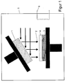
- Die Herstellung geschieht mittels sogenanntem PVD-Verfahren (Physical Vapour Deposition). Dieses Verfahren ist in Figur 1 schematisch dargestellt. Dabei wird in einer Vakuumkammer (5) durch Sublimation (oder Sieden) einer festen (oder geschmolzenen) Materialquelle oder Target (1) ein Dampf (2) erzeugt. Die Dampfatome oder -moleküle bewegen sich von der Quelle zum Substrat (3) und kondensieren dort zu einem festen Film (4). Unterschiedliche Aufdampfverfahren unterscheiden sich in der Art wie das Verdampfermaterial aufgeheizt wird: Bogen-Verfahren (auch Arc-Verfahren), Elektronenstrahl-Verfahren, Laser-Verfahren, Molekularstrahl-Epitaxie sowie Thermisches Verfahren. Das Bogenverdampfen (auch Arc-Verdampfen) ist eine spezielle Form des Aufdampfens (siehe Figur 2). Zwischen Anode und dem als Kathode geschalteten Target (Ausgangsmaterial) (1) wird ein Lichtbogen (7) gezündet, der auf der Kathodenoberfläche "wandert". Dort wo der Lichtbogen auf das Target trifft, wird das Material in den gasförmigen Zustand (2) überführt und aufgrund der hohen Ströme und Leistungsdichten zu einem hohen Prozentsatz ionisiert. Das Gas und die Ionen treffen auf das Substrat (3) und führen dort zur Schichtbildung (4).
- Bevor die zu beschichtenden Elemente mit einer Beschichtung versehen werden können, müssen sie zuerst absolut fettfrei und mikroskopisch sauber, trocken und frei von jeglichen Oxiden sein. Diese Vorreinigung kann bei der erfindungsgemässen Beschichtung z. B. mit einer 12-Kammer-Ultraschall-Reinigungsanlage geschehen. Anschliessend werden die vorbehandelten Elemente in einen Rezipienten (Beschichtungsanlage) (5) gebracht und an speziellen Halterungen befestigt, die stabil genug für eine Doppel- oder Dreifachrotation sind. Nach Schliessen der Türen wird der Rezipient evakuiert, bis ein Endvakuum von mindestens 1,0 x 10⁻⁶ mbar vorliegt. Um dieses Vakuum zu erreichen, werden z. B. Turbomolekularpumpen verwendet.
- Bei der Beschichtung ist es vorteilhaft, wenn die zu beschichteten Elemente bzw. Substrate eine gewisse Temperatur haben, wie beispielsweise ca. 200°C, um so durch epitaktisches Wachstum eine bessere Haftung auf der Oberfläche zu erzeugen. Allerdings ist die beim Substrat bzw. zu beschichtenden Teil einzustellende Anfangstemperatur vom Material des zu beschichtenden Elementes abhängig und kann somit variieren bzw. vom obengenannten Wert abweichen. Die Anfangstemperatur kann in der Anlage, beispielsweise mittels einer elektronischen Infrarotheizung (6), gesteuert werden, wobei dies in der Regel in einem Bereich von ca. 80°C bis ca. 500°C möglich ist. Für die erfindungsgemässe Beschichtung wird der Inhalt des Rezipienten auf ca. 200°C - 250°C aufgeheizt.
- Dann kann die Titanoxid-Schicht, die sich auf der Oberfläche von Titan und Titanlegierungen durch Oxidation automatisch gebildet hat, teilweise oder komplett entfernt werden, da sie die Anhaftung der Beschichtung reduzieren bzw. sogar verhindern kann. Durch das angelegte Vakuum im Rezipienten (5) wird dabei eine sofortige Zurückbildung der Oxid-Schicht verhindert und die Oberfläche ist somit perfekt vorbereitet für den anschliessenden Beschichtungsvorgang. Die beschriebene Vorbereitung der Oberfläche kann durch das Zünden einer Plasmareinigung bei sehr hoher Spannung (500 - 1400 V) im Vakuum geschehen. Dabei werden Metallionen mit sehr grosser Energie (dreifacher Schallgeschwindigkeit) auf die Oberfläche geschossen (lonenätzen). Dies geschieht mit einer solcher Wucht, dass die lonen nicht auf der Oberfläche haften bleiben. Zudem wird (wenig) Edelgas (z. B. Neon oder Argon) über ein Ventil (14) eingelassen, damit die abgesputterten lonen besser abgesaugt werden können. Eine Vorbereitung der Oberfläche ist jedoch auch über Trocken-Ätzen oder RIE-Verfahren (reactive ion etching) möglich.
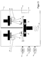
- Anschliessend beginnt das eigentliche Beschichten (siehe auch Figur 3). Die erfindungsgemässe Beschichtung entsteht nun durch das abwechselnde Zünden verschiedener Metall-Targets (10 und 20). Besonders bevorzugt sind hierbei das abwechselnde Zünden eines Targets aus reinem Zirkon und eines Targets aus reinem Chrom, prinzipiell sind jedoch auch andere Metalle wie Gold, Silber, Eisen, Titan, Niob, Hafnium oder eine geeignete Legierung denkbar. Dadurch entsteht eine aufgedampfte Mehrschichten-Struktur (auch "Sandwich-Struktur" oder "layer by layer"). Das Verfahren wird mit mindestens zwei verschiedenen Metall-Targets durchgeführt, jedoch sind auch Verfahren geeignet, bei denen mehr als zwei Metalle oder Metalllegierungen abgeschieden werden. Besonders bevorzugt sind Beschichtungen aus zwei oder mehr Metall-Targets, bei denen der Anteil des ersten Metalls oder der ersten Metalllegierung im Vergleich zur Gesamtmenge an Metall in der Beschichtung zwischen 30 und 70 Atomprozent liegt, insbesondere zwischen 40 und 60 Atomprozent, besonders bevorzugt zwischen 45 und 55 Atomprozent liegt.
- Auf einer Metallplatte (Target) (10), die z. B. aus reinstem Zirkon besteht, wird ein Lichtbogen (11) gezündet, der punktuell ca. 6.000°C hat. Das Target wird dabei von der Rückseite gekühlt, damit es nicht aufschmilzt, denn es sollte nie eine Temperatur von 250°C überschreiten. Die gelösten Metallionen werden nun mittels einer Bias-Spannung (Minus-Spannung) nochmals beschleunigt, damit sie sich auf der zu beschichtenden Oberfläche (14) "aufschweissen". Auf dem Flug vom Target zu dem zu beschichtenden Teil nimmt nun das Metall-Ion noch ein Atom Stickstoff auf (N2), welches beim Beschichten im Rezipienten zur Verfügung gestellt wird (12). Analog wird ein zweiter Lichtbogen (21) auf einem zweiten Target (20), das z. B. aus reinstem Chrom besteht, gezündet. Durch die Montage der zu beschichtenden Elemente auf einem rotierenden Teller (30), entsteht die oben beschriebene Mehrschichtenstruktur. Um eine vollständige und gleichmässige Beschichtung zu erreichen, wird nicht nur der Teller rotiert (31), sondern auch die montierten Elemente an sich (32). In einer grossen Beschichtungsanlage sollte eine Dreifachrotation gewährleistet werden.
- Ausgegangen wird von einem Anfangsvakuum von kleiner als 10-5 mbar, vorzugsweise von einem Vakuum von ca. 2,0 x 10⁻⁶ mbar. Bei der anschliessenden Beschichtung des Substrates wird das Vakuum durch Einlassen von Gasen wie Stickstoff (12) oder Azetylen (13) reduziert und pendelt sich in der Regel in einem Wertebereich von ca. 10-2 bis 10-3 mbar ein. Dabei kann z. B. von reinem Stickstoff, von reinem Azetylen oder einem Gemisch von Stickstoff und Azetylen ausgegangen werden, wobei entsprechend Metallnitride, -carbide und/oder - carbonitride abgeschieden werden.
- Gemäss einer bevorzugten Ausführungsvariante des erfindungsgemässen Verfahrens wird die Zusammensetzung des Gases während der Beschichtung verändert, so dass sich auch die Zusammensetzung in der Beschichtung während dem Beschichtungsvorgang ändert. Gemäss bevorzugter Ausführung werden anfänglich Nitride ausgeschieden. Zum Stickstoff wird nun Kohlenstoff in Form von Azetylen eingelassen, wodurch zunehmend Carbonitride in der Schicht mitabgeschieden werden. Der Kohlenstoffanteil verläuft vorzugsweise linear zunehmend, d. h. Azetylengas wird von einer anfänglichen Konzentration in der Grössenordnung von ca. 0 - 1 % auf ca. 30 - 35 % angehoben, womit entsprechend der Anteil Carbonitride in der Beschichtung zunimmt.
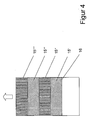
- Dadurch, dass quasi ein atomarer Aufbau der Schicht vorliegt, muss mit einer "Aufwachsrate" der Beschichtung von ca. 0,5 µm pro Beschichtungsstunde gerechnet werden. Eine Beschichtung (15) dauert vom Schliessen der Tür des Rezipienten bis zum Wiederöffnen - je nach "Dicke" der Schicht - bis zu mehreren Stunden. In Figur 4 ist schematisch veranschaulicht, dass die erfinderische Beschichtung aus mehreren Einzelschichten (15', 15", 15"', 15"" usw.) besteht, insgesamt ergeben sich so bis zu 200 Einzelschichten aufgebracht auf die Oberfläche (16) des jeweiligen Elementes.
- Eine bevorzugte Variante ist eine Multilayer-Beschichtung mit Zirkon und Chrom und Einleitung von Stickstoff und Azetylen (ZrCrCN). Übertragungsteile, die mit dieser Beschichtung überzogen wurden, verklemmen oder verschweissen sich nicht mehr mit den Implantaten, auch nicht bei der Lagerung in einer Flüssigkeit. In einem PVD-Verfahren wird dabei eine Kombination von Chrom und Zirkon unter Kohlenstoff- und Stickstoff-Partialdruck aufgedampft. Anfänglich wird dabei ZrN (Zirkonnitrid) alternierend mit CrN (Chromnitrid) aufgebracht. Im Verlauf des Verfahrens wird mittels Azetylenzugabe der Kohlenstoffgehalt von 0.5% auf bis zu 60% erhöht. Insgesamt werden bis zu 200 Schichten aufgebracht, welche eine totale Schichtdicke von einigen Mikrometern darstellen. Der Prozess findet im Hochvakuum statt und die Übertragungsteile werden zur homogenen Beschichtung einer dreifach Rotation ausgesetzt.
- Nach der Beschichtung werden die Elemente dem Rezipienten (5) entnommen und einer abschliessenden Reinigung unterworfen. Diese Reinigung dient zum einen der Entfernung von kleinen Verschmutzungen, die z. B. beim Belüften des Rezipienten aufgewirbelt werden und sich auf den beschichteten Elementen ablagern können. Zum anderen kann auf diese Weise die Oberflächeneigenschaft der Beschichtung noch etwas verändert und verbessert werden, je nach Wahl des Reinigungsmittels und -verfahrens. Für den Fachmann ist es kein Problem ein geeignetes Standardverfahren auszuwählen. Es sollte jedoch darauf geachtet werden, dass das Reinigungsmittel biokompatibel ist, damit eventuell anhaftenden Reste keine Probleme erzeugen. Als besonders geeignet erscheint ein wasserlösliches Reinigungsmittel, das die Oberfläche hydrophil macht und schnell abtrocknet.
- Die erfindungsgemässe Herstellung umfasst somit ein PVD-Verfahren mit folgenden Schritten:
- Vorreinigung ausserhalb des Vakuums
- Positionieren der Elemente im Rezipienten
- Anlegen eines Vakuum
- Vorbehandlung der Titan- oder Titanlegierungs-Oberfläche durch Edelgas-Sputtern
- Abwechselnde Abscheidung von Chrom und Zirkon in Stickstoff- und Azetylen-Atmosphäre bei konstanter Temperatur
- Lineare Veränderung des Verhältnisses von Stickstoff und Azetylen
- Belüftung
- Reinigung mit einem geeigneten Reinigungsbad
- Durch das epitaktische Wachstum werden die Spannungen in der Beschichtung auf ein Minimum reduziert und es entsteht eine hochreine, dünne, äusserst dichte, verschleiss- und korrosionsbeständige Schutzschicht. Diese ist zudem sterilisierbar, auch unter extremen Sterilisierungsbedingungen, ohne dass eine Partikelablösung beobachtet werden kann. Die Beschichtung weißt eine Härte von 3.600 HV sowie einen Reibwert trocken gegen Stahl gemessen von 0,18 auf.
- Die erfinderische Beschichtung weist eine sehr gute Schichtqualität auf. Aufgrund einer starken Bindung in der Übergangs- bzw. Interface-Zone ergibt sich eine gute Haftung zwischen Substrat und Beschichtung. Dies bildet die Vorraussetzung für eine gute und dauerhafte Adhäsion der Beschichtung. Zudem ist es wichtig, dass die Beschichtung geringe innere Spannungen aufweist, die der Bindung bzw. der Haftung entgegenwirken würden. Bei abgeschiedenen Schichten treten aus zwei Gründen innere Spannungen als Druck- oder Zugspannungen (mit Kräften parallel) zur Oberfläche auf. Zum einen entstehen thermische Spannungen durch unterschiedliche Ausdehnungskoeffizienten von beschichtetem Teil und Beschichtung bei unterschiedlichen Abscheide- und Betriebstemperaturen. Zum anderen entstehen intrinsische Spannungen durch strukturelle Unordnung der Fremd- und Schichtatome. Bei niedrig schmelzenden Metallen dominieren die thermischen Spannungen, bei hochschmelzenden Metallen dominieren hingegen die intrinsischen Spannungen. Eine hohe Temperatur bei der Abscheidung begünstigt den Platzwechsel durch Volumendiffusion und reduziert die intrinsischen Schichtspannungen. Intrinsische Spannungen können zudem durch die Wahl geeigneter Abscheideparameter (Restgasdruck, Temperatur usw.) minimiert werden. Innere Schichtspannungen können durch Verformung der Schicht abgebaut werden, dies kann jedoch zu Rissbildung (bei Zugspannung), plastisches Fliessen bei Druckspannung mit Hügelbildung sowie zu Abplatzen bzw. Delamination der Schicht führen. Die Schichtspannungen wirken den Bindungskräften somit entgegen und reduzieren die Adhäsion der Schicht. Um diese zu minimieren werden bei der erfindungsgemässen Beschichtung mehrere aufeinanderfolgende dünne Schichten von jeweils 10 bis 50 nm, alternierend aus verschiedenen Metallen oder Metalllegierungen abgeschieden. Besonders vorteilhaft ist es, wenn während dem PVD-Verfahren ein Gradient im Kohlenstoffgehalt gefahren wird. Damit ergeben sich graduelle Änderungen der Zusammensetzung und damit der physikalischen Eigenschaften ohne sprunghafte Änderungen, was zu einer weiteren Reduzierung der inneren Schichtspannungen führt.
- Ein weiterer Vorteil der erfindungsgemässen Beschichtung ist ihre Biokompatibilität. Eine sehr gute Gewebe- und Blutverträglichkeit wurde nachgewiesen. Dadurch ist sie geeignet für das Aufbringen auf Elemente, die in der Medizinaltechnik angewendet werden.
- Die Schichtdicke ist mit Hilfe des beschriebenen Verfahrens leicht einstellbar, entsprechend des Anwendungsbereiches. Bei einer Beschichtung eines Übertragungsteils, das auf ein Dentalimplantat montiert wird, empfiehlt sich eine Schichtdicke von mindestens 1 µm und von nicht mehr als 10 µm, besonders bevorzugt von nicht mehr als 5 µm.
- Zu den Anforderungen an eine qualitativ hochwertige Schicht zählt zum einen die Einhaltung einer genau definierten Schichtdicke, denn die beiden Elemente sollen weiterhin passgenau herstellbar sein und exakt aufeinander montiert werden. Auch bestimmt die Dicke die Eigenschaften der Beschichtung bezüglich Geschlossenheit und Härte. Die Aufdampfrate kann leicht über einen Schwingquarz kontrolliert werden, der mitbeschichtet wird, zudem muss der Abtrag beim Sputtern mitberücksichtigt werden. Eine hohe Reinheit der Schicht wird gewährleistet durch die Reinheit des verdampften Targetmaterials, die vorbereitenden Reinigungsschritte sowie durch den Restgasdruck. Wichtig ist zudem eine gute Kantenabdeckung, um keine offenen Stellen für den Prozess der "Kaltverschweissung" zu haben. Auch diese Bedingung wird durch die erfindungsgemässe Beschichtung erfüllt, insbesondere dadurch dass es sich nicht um eine Beschichtung mit einer einzigen Schicht handelt, sondern um eine Beschichtung mit mehreren Einzellagen. Es ist daher darauf zu achten, dass die einzelnen Schichten eine gute Homogenität aufweisen.
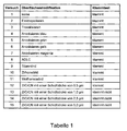
- Um die Funktionalität der erfindungsgemässen Beschichtung zu testen wurde ein sogenannter "Klemmtest" durchgeführt (siehe Tabelle 1). Dazu wurden Standard-Dentalimplantate (Straumann® Standard Plus ø 4,1 mm) aus Titan (ISO 5832-2) verwendet, Übertragungsteile gefertigt aus einer Titan-Legierung Ti6Al7Nb (ISO 5832-11) wurden mit verschiedenen Beschichtungen versehen. Der Test wurde mit Implantaten durchgeführt, die in nassem Zustand (150 mM NaCl-Lösung) mit den entsprechenden Übertragungsteilen montiert wurden. Danach wurden die Implantate mit Hilfe des Übertragungsteils bis zu einem definierten Drehmoment in ein Knochenersatzmaterial (Canevasit HGW 2082, überschliffene Version) eingedreht. Getestet wurde dabei, ob sich das Übertragungsteil anschliessend ohne Probleme und Hilfsmittel (ausgenommen vorgegebenes Kontern mit Halteschlüssel, Adapter und Ratsche) entfernen lassen konnte. Sogar beim Eindrehen eines Implantates und provozierten Bruch des Übertragungsteils an der Sollbruchstelle bei ca. 110 Ncm musste der verbleibende Rest des Übertragungsteils gut entfernt werden können. 90% der Reste sollten ohne zusätzliche Werkzeuge entfernt werden können. Wenn bei 10% der Rest des Übertragungsteils mit einer Pinzette (oder kleiner Zange) mit geringer Kraft entfernt werden kann, galt dies noch als funktionstüchtig, da keine klinische Gefährdung des Patienten vorliegen würde.
- Das Übertragungsteil in Versuch 1 wurde weder oberflächenmodifiziert noch beschichtet. In Versuch 2 wurde das Übertragungsteil elektropoliert, um im Mikrobereich eine glatte Oberfläche zu erhalten. Dabei handelt es sich um ein elektrochemisches Verfahren zum Polieren von Metallen. Das anodisch geschaltete Übertragungsteil wurde mit Gegenkathoden versehen und in einem geeigneten Elektrolyten einer Gleichspannung unterworfen. In Versuch 3 wurde die Oberfläche im Mikrobereich durch Trovalisieren verändert. Dazu wurden die Übertragungsteile in eine grosse Trommel mit speziellen Scheuerteilchen gegeben. Die Trommel wurde dann 24 Stunden gedreht, durch das Aneinanderreiben wurden zum einen Stanzgrate entfernt und Kanten verrundet und zum anderen die Oberfläche gehärtet. Bei der Anodisierung in den Versuchen 4 bis 6 ist die Oberfläche anodisiert (Verfahren zur Oberflächenbehandlung nach DIN 8580). Dabei wurde Aluminum als Anode geschaltet und dann mittels Gleichstrom in Säure elektrolysiert. Es wurden unterschiedliche Schichtdicken ausgetestet, die Anodisierungen haben je nach Dicke eine andere Farbe. Bei der ADLC-Beschichtung (Versuch 8) wurde in einem CVD-Verfahren eine reine Kohlenstoffschicht in Diamant-Koordination (sp3) aufgebracht. In Versuch 9 und 10 wurde ein PVD-Verfahren (analog dem oben beschriebenen) durchgeführt, allerdings nur mit einem Target - einmal mit reinem Zirkon, einmal mit reinem Titan, beide Male unter Zusatz von Stickstoff. Im Fall 11 wurde als Target Wolfram unter Zusatz von Azetylen getestet. In den Versuchen 12 bis 15 wurde das Übertragungsteil mit dem erfindungsgemässen Verfahren beschichtet, d. h. mit zwei verschiedenen Metallen und mit Einleitung von Azetylen und Stickstoff, hier also ZrCrCN, allerdings mit unterschiedlichen Schichtdicken zwischen 0,5 und 5,0 µm.
- Die Ergebnisse des Klemmtestes sind in Tabelle 1 veranschaulicht. Dieser ist zu entnehmen, dass nur das erfindungsgemässe Beschichtungsverfahren mit zwei verschiedenen Metallen das Problem des Kaltverschweissens löst, dies allerdings erst ab einer Schichtdicke von 1,0 µm.
- Die Erfindung wird nun beispielsweise anhand eines Ausführungsbeispieles näher erläutert.
- Die nachfolgend angeführten Arbeits- bzw. Prozessbedingungen beziehen sich auf die beim Durchführen des Beispieles einer Beschichtung für ein Übertragungsteil unter Verwendung einer Anlage vom Typ Hauzer 1000-6.
- Die zu beschichtenden Übertragungsteile werden gereinigt in den Rezipienten bzw. Reaktionsofen eingebracht. Vor Beginn des Beschichtungsprozesses wird der Reaktionsraum evakuiert auf ein Vakuum von 1 x 10⁻⁶ mbar und das Substrat aufgeheizt auf eine Temperatur von ca. 270 °C. Vor Beginn der Beschichtung wird die Oberfläche des zu beschichtende Übertragungsteil zunächst mittels lonenätzen gereinigt werden. Dabei werden folgende Prozessparameter eingestellt:
Bias: 500 - 1400 Volt Verdampfer: Einzeln bei 60 - 110 Ah Laufzeit: 8 s - Während der Dauer des Reinigungsprozesses läuft eine Turbomolekularpumpe auf voller Leistung, um allfällig beim Reinigen entstehende Verunreinigungen sofort aus dem Bearbeitungsraum entfernen zu können. Zusätzlich wird der Reinigungsprozess durch die Zugabe kleinster Mengen von Argon unterstützt.
- Bei Beginn der Beschichtungsphase wird ein Bias am Substrat angelegt von anfänglich ca. 45 V, welches im Verlaufe der Beschichtungsphase bei steigendem Azetylenanteil auf einen Bereich von ca. 25 - 40 V reduziert wird. Der Verdampfer wird bei der Beschichtungsphase gepulst oder kontinuierlich betrieben, wobei bei fortschreitender Dauer der Beschichtungsphase die Stromstärke bei steigender Azetylenkonzentration reduziert wird.
- Während der Beschichtungsphase wird ein weitgehend konstanter Stickstofffluss in der Grössenordnung von ca. 40 ppm gewählt, während gleichzeitig der Azetylenfluss von ca. 0,5 - ca. 35 % steigend gewählt wird, was ca. 1 bis 25 - 30 ppm ergibt, wobei der Anstieg des Azetylenflusses vorzugsweise linear ansteigend eingestellt wird. Der Druck im Rezipienten bzw. Reaktionsraum sollte im Bereich von ca. 5 x 10⁻³ ― 1 x 10⁻² mbar sein, und während dem gesamten Beschichtungsprozess läuft die obenerwähnte Turbomolekularpumpe lediglich mit einer Leistung von ca. 60 - 80 %. Nach dem Beschichten wird der Reaktionsraum vorsichtig belüftet und die beschichteten Übertragungsteile in einem Standardverfahren abschliessend gereinigt.
- Selbstverständlich ist die vorliegende Erfindung nicht auf die beispielsweise erwähnten Beschichtungen, Beschichtungsverfahren usw. beschränkt, sondern die vorliegende Erfindung umfasst jede Art von Beschichtungen bestehend aus mindestens zwei verschiedenen Metallen, welche nach Aufbringen auf mindestens ein Teil aus Titan oder Titanlegierung zur Vermeidung ein Kaltverschweissen bei montierten Aufbauten aus mindestens zwei Elementen aus Titan oder Titanlegierung, insbesondere bei der Lagerung in Flüssigkeiten ausschliessen.
- Desweiteren ist zu beachten, dass Elemente aus Zirkon oder Zirkon-Legierungen analog wie Elemente - aus Titan oder Titan-Legierungen den Effekt des Kaltverschweissens aufweisen. Die erfindungsgemässe Beschichtung ist daher nicht auf Elemente aus Titan oder Titan-Legierungen beschränkt, sondern kann analog für Elemente aus Zirkon oder Zirkon-Legierungen angewendet werden, um die vorbeschriebene Aufgabe zu lösen. Damit sind in dieser Erfindung Verfahren, Elemente, Beschichtungen und Kombinationen von Elementen mit eingeschlossen, bei denen die Elemente statt aus Titan oder Titan-Legierung aus Zirkon oder Zirkon-Legierung bestehen. Die vorangegangene Offenbarung gilt analog für diese Verfahren, Elemente, Beschichtungen und Kombinationen von Elementen.
Claims (16)
- PVD-Verfahren zur Beschichtung von Elementen aus Titan oder Titan-Legierung, aufweisend mindestens folgende Schrittea) Positionieren der Elemente in einem Rezipienten;b) Anlegen eines Vakuum;c) Abscheidung eines ersten Metalls oder einer ersten Metalllegierung in Stickstoff- und Azetylen-Atmosphäre;d) Abscheidung eines zweiten Metalls oder einer zweiten Metalllegierung in Stickstoff- und Azetylen-Atmosphäre;e) Wiederholung der Schritte c) und d) bis eine ausreichende Schichtdicke erreicht ist;f) Belüftung des Rezipienten;g) Entnahme der Elemente aus dem Rezipienten;h) Reinigung der Elemente mit einem geeigneten Reinigungsbad.
- Verfahren nach Anspruch 1, gekennzeichnet dadurch dass nach dem Schritt b) eine Vorbehandlung der Oberfläche durchgeführt wird, insbesondere durch Sputtern mit Edelgasen.
- Verfahren nach Anspruch 1 oder 2, gekennzeichnet dadurch dass während Schritt e) das Verhältnis von Stickstoff und / oder Azetylen verändert wird.
- Verfahren nach Anspruch 3, gekennzeichnet dadurch dass die Veränderung linear ist.
- Verfahren nach Ansprüchen 1 bis 4, gekennzeichnet dadurch dass die Schichtdicke mindestens 1 µm aufweisst.
- Verfahren nach Ansprüchen 1 bis 5, gekennzeichnet dadurch dass das erste Metall oder das zweite Metall Chrom oder / und das erste Metall oder das zweite Metall Zirkon ist.
- Verfahren nach Anspruch 1 bis 6, gekennzeichnet dadurch dass mehr als zwei Metalle oder Metalllegierungen abgeschieden werden.
- Element aus Titan oder Titan-Legierung mit einer Beschichtung hergestellt in einem Verfahren nach Ansprüchen 1 bis 7.
- Element nach Anspruch 8, bei dem es sich um ein Implantat, ein Dentalimplantat, eine Knochenschraube oder ein Übertragungsteil handelt.
- Beschichtung auf einem Element aus Titan oder Titan-Legierung hergestellt in einem Verfahren nach Ansprüchen 1 bis 7.
- Beschichtung nach Anspruch 10, gekennzeichnet dadurch dass der Anteil des ersten Metalls oder der ersten Metalllegierung im Vergleich zur Gesamtmenge an Metall in der Beschichtung zwischen 30 und 70 Atomprozent liegt, insbesondere zwischen 40 und 60 Atomprozent, besonders bevorzugt zwischen 45 und 55 Atomprozent liegt.
- Kombination von Elementen, bei denen mindestens ein Element zumindest teilweise mit einer Beschichtung nach Ansprüchen 10 oder 11 versehen ist.
- Verfahren nach Ansprüchen 1 bis 7, gekennzeichnet dadurch dass statt Elementen aus Titan oder Titan-Legierung Elemente aus Zirkon oder Zirkon-Legierung beschichtet werden.
- Element nach Ansprüchen 8 oder 9, gekennzeichnet dadurch dass diese statt aus Titan oder Titan-Legierung aus Zirkon oder Zirkon-Legierung bestehen.
- Beschichtung nach Ansprüchen 10 oder 11, gekennzeichnet dadurch dass statt Elementen aus Titan oder Titan-Legierung Elemente aus Zirkon oder Zirkon-Legierung beschichtet werden.
- Kombination nach Anspruch 12, gekennzeichnet dadurch dass statt Elementen aus Titan oder Titan-Legierung Elemente aus Zirkon oder Zirkon-Legierung kombiniert werden.
Priority Applications (5)
| Application Number | Priority Date | Filing Date | Title |
|---|---|---|---|
| EP20050019053 EP1759722B1 (de) | 2005-09-01 | 2005-09-01 | Beschichtung von Teilen aus Titan oder einer Titan-Legierung zur Verhinderung von Kaltverschweissung |
| DE200550008486 DE502005008486D1 (de) | 2005-09-01 | 2005-09-01 | Beschichtung von Teilen aus Titan oder einer Titan-Legierung zur Verhinderung von Kaltverschweissung |
| AT05019053T ATE447985T1 (de) | 2005-09-01 | 2005-09-01 | Beschichtung von teilen aus titan oder einer titan-legierung zur verhinderung von kaltverschweissung |
| PCT/EP2006/007872 WO2007025641A2 (de) | 2005-09-01 | 2006-08-09 | Beschichtung von teilen aus titan oder einer titan-legierung zur verhinderung von kaltverschweissung |
| US12/065,430 US20080248320A1 (en) | 2005-09-01 | 2006-08-09 | Coating for Parts Made of Titanium or the Alloy Thereof or Preventing Cold Welding |
Applications Claiming Priority (1)
| Application Number | Priority Date | Filing Date | Title |
|---|---|---|---|
| EP20050019053 EP1759722B1 (de) | 2005-09-01 | 2005-09-01 | Beschichtung von Teilen aus Titan oder einer Titan-Legierung zur Verhinderung von Kaltverschweissung |
Publications (2)
| Publication Number | Publication Date |
|---|---|
| EP1759722A1 true EP1759722A1 (de) | 2007-03-07 |
| EP1759722B1 EP1759722B1 (de) | 2009-11-11 |
Family
ID=35588963
Family Applications (1)
| Application Number | Title | Priority Date | Filing Date |
|---|---|---|---|
| EP20050019053 Expired - Lifetime EP1759722B1 (de) | 2005-09-01 | 2005-09-01 | Beschichtung von Teilen aus Titan oder einer Titan-Legierung zur Verhinderung von Kaltverschweissung |
Country Status (5)
| Country | Link |
|---|---|
| US (1) | US20080248320A1 (de) |
| EP (1) | EP1759722B1 (de) |
| AT (1) | ATE447985T1 (de) |
| DE (1) | DE502005008486D1 (de) |
| WO (1) | WO2007025641A2 (de) |
Families Citing this family (3)
| Publication number | Priority date | Publication date | Assignee | Title |
|---|---|---|---|---|
| JP4162094B2 (ja) * | 2006-05-30 | 2008-10-08 | 三菱重工業株式会社 | 常温接合によるデバイス、デバイス製造方法ならびに常温接合装置 |
| US9782260B1 (en) * | 2014-01-29 | 2017-10-10 | Lucas Anissian | Materials and methods for prevention of cold welding, corrosion and tissue overgrowth between medical implant components |
| US12465987B2 (en) | 2019-12-19 | 2025-11-11 | Honeywell Federal Manufacturing & Technologies, Llc | Solderable coating for additive manufactured oxidizing metals |
Citations (11)
| Publication number | Priority date | Publication date | Assignee | Title |
|---|---|---|---|---|
| FR2576793A1 (fr) * | 1985-01-31 | 1986-08-08 | Rhenter Jean Luc | Prothese articulaire perfectionnee en titane |
| EP0295397A1 (de) * | 1987-06-17 | 1988-12-21 | GebràDer Sulzer Aktiengesellschaft | Metallisches Implantat |
| EP0401488A1 (de) * | 1989-06-07 | 1990-12-12 | Detlev Dr. Repenning | Verfahren zur Herstellung hochharter Schichten auf Titanwerkstoffen sowie ihren Legierungen |
| EP0418905A2 (de) * | 1989-09-22 | 1991-03-27 | Dornier Luftfahrt Gmbh | Korrosions- und reibbeständige Beschichtungen |
| WO1998055039A1 (de) | 1997-06-02 | 1998-12-10 | Institut Straumann Ag | Halteelement für ein implantat und ampulle zur aufbewahrung des implantats |
| WO2000002496A1 (en) | 1998-07-13 | 2000-01-20 | Nobel Biocare Ab | Combination implant carrier and vial cap |
| US6206696B1 (en) | 1999-12-10 | 2001-03-27 | Sulzer Calcitek Inc. | Driver tool for one step implant delivery system |
| US6247932B1 (en) | 1997-05-26 | 2001-06-19 | Franz Sutter | Container holding a cartridge and a dental implant arranged therein |
| WO2001050978A1 (en) | 2000-01-14 | 2001-07-19 | Nobel Biocare Ab | Universal implant delivery system |
| EP1136585A1 (de) * | 2000-03-21 | 2001-09-26 | Logotherm AG | Hartstoffschicht mit selbstschmierenden Eigenschaften |
| EP1150620A1 (de) | 1999-01-29 | 2001-11-07 | Institut Straumann AG | Osteophile implantate |
-
2005
- 2005-09-01 AT AT05019053T patent/ATE447985T1/de not_active IP Right Cessation
- 2005-09-01 EP EP20050019053 patent/EP1759722B1/de not_active Expired - Lifetime
- 2005-09-01 DE DE200550008486 patent/DE502005008486D1/de not_active Expired - Lifetime
-
2006
- 2006-08-09 US US12/065,430 patent/US20080248320A1/en not_active Abandoned
- 2006-08-09 WO PCT/EP2006/007872 patent/WO2007025641A2/de not_active Ceased
Patent Citations (11)
| Publication number | Priority date | Publication date | Assignee | Title |
|---|---|---|---|---|
| FR2576793A1 (fr) * | 1985-01-31 | 1986-08-08 | Rhenter Jean Luc | Prothese articulaire perfectionnee en titane |
| EP0295397A1 (de) * | 1987-06-17 | 1988-12-21 | GebràDer Sulzer Aktiengesellschaft | Metallisches Implantat |
| EP0401488A1 (de) * | 1989-06-07 | 1990-12-12 | Detlev Dr. Repenning | Verfahren zur Herstellung hochharter Schichten auf Titanwerkstoffen sowie ihren Legierungen |
| EP0418905A2 (de) * | 1989-09-22 | 1991-03-27 | Dornier Luftfahrt Gmbh | Korrosions- und reibbeständige Beschichtungen |
| US6247932B1 (en) | 1997-05-26 | 2001-06-19 | Franz Sutter | Container holding a cartridge and a dental implant arranged therein |
| WO1998055039A1 (de) | 1997-06-02 | 1998-12-10 | Institut Straumann Ag | Halteelement für ein implantat und ampulle zur aufbewahrung des implantats |
| WO2000002496A1 (en) | 1998-07-13 | 2000-01-20 | Nobel Biocare Ab | Combination implant carrier and vial cap |
| EP1150620A1 (de) | 1999-01-29 | 2001-11-07 | Institut Straumann AG | Osteophile implantate |
| US6206696B1 (en) | 1999-12-10 | 2001-03-27 | Sulzer Calcitek Inc. | Driver tool for one step implant delivery system |
| WO2001050978A1 (en) | 2000-01-14 | 2001-07-19 | Nobel Biocare Ab | Universal implant delivery system |
| EP1136585A1 (de) * | 2000-03-21 | 2001-09-26 | Logotherm AG | Hartstoffschicht mit selbstschmierenden Eigenschaften |
Non-Patent Citations (2)
| Title |
|---|
| LIU X ET AL: "Surface modification of titanium, titanium alloys, and related materials for biomedical applications", MATERIALS SCIENCE AND ENGINEERING R: REPORTS, ELSEVIER SEQUOIA S.A., LAUSANNE, CH, vol. 47, no. 3-4, 24 December 2004 (2004-12-24), pages 49 - 121, XP004722113, ISSN: 0927-796X * |
| THULL R: "Development And Electrochemical Evaluation Of Two PVD-hard Coatings For Implants Made Of Titanium", ENGINEERING IN MEDICINE AND BIOLOGY SOCIETY, 1991. VOL.13: 1991., PROCEEDINGS OF THE ANNUAL INTERNATIONAL CONFERENCE OF THE IEEE ORLANDO, FL, USA 31 OCT.-3 NOV. 1991, NEW YORK, NY, USA,IEEE, US, 31 October 1991 (1991-10-31), pages 1477 - 1478, XP010102162, ISBN: 0-7803-0216-8 * |
Also Published As
| Publication number | Publication date |
|---|---|
| US20080248320A1 (en) | 2008-10-09 |
| ATE447985T1 (de) | 2009-11-15 |
| WO2007025641A3 (de) | 2007-04-26 |
| DE502005008486D1 (de) | 2009-12-24 |
| EP1759722B1 (de) | 2009-11-11 |
| WO2007025641A2 (de) | 2007-03-08 |
Similar Documents
| Publication | Publication Date | Title |
|---|---|---|
| KR100714244B1 (ko) | 생체용 골유도성 금속 임플란트 및 그 제조방법 | |
| Hallmann et al. | Effect of sputtering parameters and substrate composition on the structure of tantalum thin films | |
| EP2211754B1 (de) | Dental-Implantansystem | |
| EP2732068B1 (de) | Verfahren zur verbesserung der verschleissbeständigkeit von eingefärbten chirurgischen instrumenten | |
| US10166105B2 (en) | Self-detaching layer for easy implant removal | |
| DE102013102370A1 (de) | Verfahren zur Herstellung eines funktionalisierten Implantats sowie funktionalisiertes Implantat | |
| EP1763375A1 (de) | Interferenz-erzeugende, farbige beschichtung für chirurgische implantate und instrumente | |
| EP1759722B1 (de) | Beschichtung von Teilen aus Titan oder einer Titan-Legierung zur Verhinderung von Kaltverschweissung | |
| US20130030361A1 (en) | Coated medical implant | |
| US20070083269A1 (en) | Method of producing endosseous implants or medical prostheses by means of ion implantation and endosseous implant or medical prosthesis thus obtained | |
| DE2632932A1 (de) | Implantat, insbesondere zahnimplantat | |
| CN112088019A (zh) | 抗微生物的植入物涂层 | |
| EP2439183B1 (de) | Monolithischer Keramikkörper mit Mischoxid-Randbereich und metallischer Oberfläche, Verfahren zu dessen Herstellung und dessen Verwendung | |
| WO1998026721A1 (de) | Medizinische schere mit verschleissmindernder beschichtung | |
| EP3730162B1 (de) | Duktile beschichtung für eine implantatkomponente | |
| Toth et al. | Titanium implants with oxidized surfaces: the background and long-term results | |
| DE10158302A1 (de) | Beschichtung von implantierbaren Metallkörpern mit bioaktiven Materialien | |
| EP1334737A2 (de) | Antihaftbeschichtung sowie deren Verwendung | |
| WO2026052635A1 (de) | Distraktorvorrichtung | |
| KR20250085287A (ko) | 플라즈마 전해 산화법을 이용한 티타늄계 합금의 임플란트 제조방법 및 코팅방법 | |
| KR20250085283A (ko) | 플라즈마 전해 산화법을 이용한 티타늄계 합금의 임플란트 제조방법 및 코팅방법 | |
| KR20250085290A (ko) | 플라즈마 전해 산화법을 이용한 티타늄계 합금의 임플란트 제조방법 및 코팅방법 | |
| CROITORU et al. | Materials and Technologies Used in Present Dental Implants Manufacturing |
Legal Events
| Date | Code | Title | Description |
|---|---|---|---|
| PUAI | Public reference made under article 153(3) epc to a published international application that has entered the european phase |
Free format text: ORIGINAL CODE: 0009012 |
|
| AK | Designated contracting states |
Kind code of ref document: A1 Designated state(s): AT BE BG CH CY CZ DE DK EE ES FI FR GB GR HU IE IS IT LI LT LU LV MC NL PL PT RO SE SI SK TR |
|
| AX | Request for extension of the european patent |
Extension state: AL BA HR MK YU |
|
| 17P | Request for examination filed |
Effective date: 20070830 |
|
| 17Q | First examination report despatched |
Effective date: 20070926 |
|
| AKX | Designation fees paid |
Designated state(s): AT BE BG CH CY CZ DE DK EE ES FI FR GB GR HU IE IS IT LI LT LU LV MC NL PL PT RO SE SI SK TR |
|
| GRAP | Despatch of communication of intention to grant a patent |
Free format text: ORIGINAL CODE: EPIDOSNIGR1 |
|
| GRAS | Grant fee paid |
Free format text: ORIGINAL CODE: EPIDOSNIGR3 |
|
| GRAA | (expected) grant |
Free format text: ORIGINAL CODE: 0009210 |
|
| AK | Designated contracting states |
Kind code of ref document: B1 Designated state(s): AT BE BG CH CY CZ DE DK EE ES FI FR GB GR HU IE IS IT LI LT LU LV MC NL PL PT RO SE SI SK TR |
|
| REG | Reference to a national code |
Ref country code: GB Ref legal event code: FG4D Free format text: NOT ENGLISH |
|
| REG | Reference to a national code |
Ref country code: CH Ref legal event code: EP |
|
| REG | Reference to a national code |
Ref country code: IE Ref legal event code: FG4D |
|
| REF | Corresponds to: |
Ref document number: 502005008486 Country of ref document: DE Date of ref document: 20091224 Kind code of ref document: P |
|
| NLV1 | Nl: lapsed or annulled due to failure to fulfill the requirements of art. 29p and 29m of the patents act | ||
| LTIE | Lt: invalidation of european patent or patent extension |
Effective date: 20091111 |
|
| PG25 | Lapsed in a contracting state [announced via postgrant information from national office to epo] |
Ref country code: LT Free format text: LAPSE BECAUSE OF FAILURE TO SUBMIT A TRANSLATION OF THE DESCRIPTION OR TO PAY THE FEE WITHIN THE PRESCRIBED TIME-LIMIT Effective date: 20091111 Ref country code: ES Free format text: LAPSE BECAUSE OF FAILURE TO SUBMIT A TRANSLATION OF THE DESCRIPTION OR TO PAY THE FEE WITHIN THE PRESCRIBED TIME-LIMIT Effective date: 20100222 Ref country code: FI Free format text: LAPSE BECAUSE OF FAILURE TO SUBMIT A TRANSLATION OF THE DESCRIPTION OR TO PAY THE FEE WITHIN THE PRESCRIBED TIME-LIMIT Effective date: 20091111 Ref country code: IS Free format text: LAPSE BECAUSE OF FAILURE TO SUBMIT A TRANSLATION OF THE DESCRIPTION OR TO PAY THE FEE WITHIN THE PRESCRIBED TIME-LIMIT Effective date: 20100311 Ref country code: SE Free format text: LAPSE BECAUSE OF FAILURE TO SUBMIT A TRANSLATION OF THE DESCRIPTION OR TO PAY THE FEE WITHIN THE PRESCRIBED TIME-LIMIT Effective date: 20091111 Ref country code: PT Free format text: LAPSE BECAUSE OF FAILURE TO SUBMIT A TRANSLATION OF THE DESCRIPTION OR TO PAY THE FEE WITHIN THE PRESCRIBED TIME-LIMIT Effective date: 20100311 |
|
| PG25 | Lapsed in a contracting state [announced via postgrant information from national office to epo] |
Ref country code: PL Free format text: LAPSE BECAUSE OF FAILURE TO SUBMIT A TRANSLATION OF THE DESCRIPTION OR TO PAY THE FEE WITHIN THE PRESCRIBED TIME-LIMIT Effective date: 20091111 Ref country code: LV Free format text: LAPSE BECAUSE OF FAILURE TO SUBMIT A TRANSLATION OF THE DESCRIPTION OR TO PAY THE FEE WITHIN THE PRESCRIBED TIME-LIMIT Effective date: 20091111 Ref country code: CY Free format text: LAPSE BECAUSE OF FAILURE TO SUBMIT A TRANSLATION OF THE DESCRIPTION OR TO PAY THE FEE WITHIN THE PRESCRIBED TIME-LIMIT Effective date: 20091111 Ref country code: SI Free format text: LAPSE BECAUSE OF FAILURE TO SUBMIT A TRANSLATION OF THE DESCRIPTION OR TO PAY THE FEE WITHIN THE PRESCRIBED TIME-LIMIT Effective date: 20091111 |
|
| REG | Reference to a national code |
Ref country code: IE Ref legal event code: FD4D |
|
| PG25 | Lapsed in a contracting state [announced via postgrant information from national office to epo] |
Ref country code: EE Free format text: LAPSE BECAUSE OF FAILURE TO SUBMIT A TRANSLATION OF THE DESCRIPTION OR TO PAY THE FEE WITHIN THE PRESCRIBED TIME-LIMIT Effective date: 20091111 Ref country code: IE Free format text: LAPSE BECAUSE OF FAILURE TO SUBMIT A TRANSLATION OF THE DESCRIPTION OR TO PAY THE FEE WITHIN THE PRESCRIBED TIME-LIMIT Effective date: 20091111 Ref country code: BG Free format text: LAPSE BECAUSE OF FAILURE TO SUBMIT A TRANSLATION OF THE DESCRIPTION OR TO PAY THE FEE WITHIN THE PRESCRIBED TIME-LIMIT Effective date: 20100211 Ref country code: DK Free format text: LAPSE BECAUSE OF FAILURE TO SUBMIT A TRANSLATION OF THE DESCRIPTION OR TO PAY THE FEE WITHIN THE PRESCRIBED TIME-LIMIT Effective date: 20091111 Ref country code: RO Free format text: LAPSE BECAUSE OF FAILURE TO SUBMIT A TRANSLATION OF THE DESCRIPTION OR TO PAY THE FEE WITHIN THE PRESCRIBED TIME-LIMIT Effective date: 20091111 |
|
| PG25 | Lapsed in a contracting state [announced via postgrant information from national office to epo] |
Ref country code: CZ Free format text: LAPSE BECAUSE OF FAILURE TO SUBMIT A TRANSLATION OF THE DESCRIPTION OR TO PAY THE FEE WITHIN THE PRESCRIBED TIME-LIMIT Effective date: 20091111 Ref country code: SK Free format text: LAPSE BECAUSE OF FAILURE TO SUBMIT A TRANSLATION OF THE DESCRIPTION OR TO PAY THE FEE WITHIN THE PRESCRIBED TIME-LIMIT Effective date: 20091111 |
|
| PLBE | No opposition filed within time limit |
Free format text: ORIGINAL CODE: 0009261 |
|
| STAA | Information on the status of an ep patent application or granted ep patent |
Free format text: STATUS: NO OPPOSITION FILED WITHIN TIME LIMIT |
|
| 26N | No opposition filed |
Effective date: 20100812 |
|
| PG25 | Lapsed in a contracting state [announced via postgrant information from national office to epo] |
Ref country code: GR Free format text: LAPSE BECAUSE OF FAILURE TO SUBMIT A TRANSLATION OF THE DESCRIPTION OR TO PAY THE FEE WITHIN THE PRESCRIBED TIME-LIMIT Effective date: 20100212 |
|
| BERE | Be: lapsed |
Owner name: STRAUMANN HOLDING A.G. Effective date: 20100930 |
|
| PG25 | Lapsed in a contracting state [announced via postgrant information from national office to epo] |
Ref country code: IT Free format text: LAPSE BECAUSE OF FAILURE TO SUBMIT A TRANSLATION OF THE DESCRIPTION OR TO PAY THE FEE WITHIN THE PRESCRIBED TIME-LIMIT Effective date: 20091111 |
|
| PG25 | Lapsed in a contracting state [announced via postgrant information from national office to epo] |
Ref country code: MC Free format text: LAPSE BECAUSE OF NON-PAYMENT OF DUE FEES Effective date: 20100930 |
|
| REG | Reference to a national code |
Ref country code: CH Ref legal event code: PL |
|
| GBPC | Gb: european patent ceased through non-payment of renewal fee |
Effective date: 20100901 |
|
| REG | Reference to a national code |
Ref country code: FR Ref legal event code: ST Effective date: 20110531 |
|
| REG | Reference to a national code |
Ref country code: DE Ref legal event code: R119 Ref document number: 502005008486 Country of ref document: DE Effective date: 20110401 |
|
| PG25 | Lapsed in a contracting state [announced via postgrant information from national office to epo] |
Ref country code: DE Free format text: LAPSE BECAUSE OF NON-PAYMENT OF DUE FEES Effective date: 20110401 Ref country code: CH Free format text: LAPSE BECAUSE OF NON-PAYMENT OF DUE FEES Effective date: 20100930 Ref country code: FR Free format text: LAPSE BECAUSE OF NON-PAYMENT OF DUE FEES Effective date: 20100930 Ref country code: BE Free format text: LAPSE BECAUSE OF NON-PAYMENT OF DUE FEES Effective date: 20100930 Ref country code: LI Free format text: LAPSE BECAUSE OF NON-PAYMENT OF DUE FEES Effective date: 20100930 |
|
| PG25 | Lapsed in a contracting state [announced via postgrant information from national office to epo] |
Ref country code: GB Free format text: LAPSE BECAUSE OF NON-PAYMENT OF DUE FEES Effective date: 20100901 |
|
| PG25 | Lapsed in a contracting state [announced via postgrant information from national office to epo] |
Ref country code: AT Free format text: LAPSE BECAUSE OF NON-PAYMENT OF DUE FEES Effective date: 20100901 |
|
| PG25 | Lapsed in a contracting state [announced via postgrant information from national office to epo] |
Ref country code: LU Free format text: LAPSE BECAUSE OF NON-PAYMENT OF DUE FEES Effective date: 20100901 Ref country code: HU Free format text: LAPSE BECAUSE OF FAILURE TO SUBMIT A TRANSLATION OF THE DESCRIPTION OR TO PAY THE FEE WITHIN THE PRESCRIBED TIME-LIMIT Effective date: 20100512 Ref country code: NL Free format text: LAPSE BECAUSE OF FAILURE TO SUBMIT A TRANSLATION OF THE DESCRIPTION OR TO PAY THE FEE WITHIN THE PRESCRIBED TIME-LIMIT Effective date: 20091111 |
|
| PG25 | Lapsed in a contracting state [announced via postgrant information from national office to epo] |
Ref country code: TR Free format text: LAPSE BECAUSE OF FAILURE TO SUBMIT A TRANSLATION OF THE DESCRIPTION OR TO PAY THE FEE WITHIN THE PRESCRIBED TIME-LIMIT Effective date: 20091111 |