EP1759178B1 - Vibration-type transducer - Google Patents
Vibration-type transducer Download PDFInfo
- Publication number
- EP1759178B1 EP1759178B1 EP05754571.7A EP05754571A EP1759178B1 EP 1759178 B1 EP1759178 B1 EP 1759178B1 EP 05754571 A EP05754571 A EP 05754571A EP 1759178 B1 EP1759178 B1 EP 1759178B1
- Authority
- EP
- European Patent Office
- Prior art keywords
- measuring tube
- transducer
- support element
- vibration
- previous
- Prior art date
- Legal status (The legal status is an assumption and is not a legal conclusion. Google has not performed a legal analysis and makes no representation as to the accuracy of the status listed.)
- Active
Links
- 239000012530 fluid Substances 0.000 claims description 44
- 230000008878 coupling Effects 0.000 claims description 37
- 238000010168 coupling process Methods 0.000 claims description 37
- 238000005859 coupling reaction Methods 0.000 claims description 37
- 230000009471 action Effects 0.000 claims description 7
- 230000005489 elastic deformation Effects 0.000 claims description 3
- 238000005452 bending Methods 0.000 description 35
- 230000010355 oscillation Effects 0.000 description 30
- 230000005284 excitation Effects 0.000 description 20
- 230000001419 dependent effect Effects 0.000 description 10
- 230000008901 benefit Effects 0.000 description 6
- 238000009826 distribution Methods 0.000 description 5
- 230000000694 effects Effects 0.000 description 5
- 230000005520 electrodynamics Effects 0.000 description 5
- 239000000463 material Substances 0.000 description 5
- 230000001133 acceleration Effects 0.000 description 4
- 230000000712 assembly Effects 0.000 description 3
- 238000000429 assembly Methods 0.000 description 3
- 238000011156 evaluation Methods 0.000 description 3
- 230000001965 increasing effect Effects 0.000 description 3
- 238000009434 installation Methods 0.000 description 3
- 238000004519 manufacturing process Methods 0.000 description 3
- 238000004513 sizing Methods 0.000 description 3
- 230000003068 static effect Effects 0.000 description 3
- RTAQQCXQSZGOHL-UHFFFAOYSA-N Titanium Chemical compound [Ti] RTAQQCXQSZGOHL-UHFFFAOYSA-N 0.000 description 2
- 238000006243 chemical reaction Methods 0.000 description 2
- 230000005484 gravity Effects 0.000 description 2
- 239000007788 liquid Substances 0.000 description 2
- 238000006386 neutralization reaction Methods 0.000 description 2
- 230000009467 reduction Effects 0.000 description 2
- 230000001105 regulatory effect Effects 0.000 description 2
- 230000001953 sensory effect Effects 0.000 description 2
- 239000010936 titanium Substances 0.000 description 2
- 229910000851 Alloy steel Inorganic materials 0.000 description 1
- 229920000049 Carbon (fiber) Polymers 0.000 description 1
- 101100390736 Danio rerio fign gene Proteins 0.000 description 1
- 101100390738 Mus musculus Fign gene Proteins 0.000 description 1
- 229910001362 Ta alloys Inorganic materials 0.000 description 1
- 229910001069 Ti alloy Inorganic materials 0.000 description 1
- QCWXUUIWCKQGHC-UHFFFAOYSA-N Zirconium Chemical compound [Zr] QCWXUUIWCKQGHC-UHFFFAOYSA-N 0.000 description 1
- 229910001093 Zr alloy Inorganic materials 0.000 description 1
- 210000001015 abdomen Anatomy 0.000 description 1
- 230000004323 axial length Effects 0.000 description 1
- 238000005219 brazing Methods 0.000 description 1
- 239000004917 carbon fiber Substances 0.000 description 1
- 239000000919 ceramic Substances 0.000 description 1
- 238000004140 cleaning Methods 0.000 description 1
- 238000013016 damping Methods 0.000 description 1
- 238000001514 detection method Methods 0.000 description 1
- 230000001627 detrimental effect Effects 0.000 description 1
- 238000011161 development Methods 0.000 description 1
- 230000018109 developmental process Effects 0.000 description 1
- 238000006073 displacement reaction Methods 0.000 description 1
- 230000000763 evoking effect Effects 0.000 description 1
- 239000011521 glass Substances 0.000 description 1
- 239000003365 glass fiber Substances 0.000 description 1
- 239000002241 glass-ceramic Substances 0.000 description 1
- 238000011835 investigation Methods 0.000 description 1
- 238000005259 measurement Methods 0.000 description 1
- 230000010358 mechanical oscillation Effects 0.000 description 1
- 230000007246 mechanism Effects 0.000 description 1
- 238000000034 method Methods 0.000 description 1
- 230000005693 optoelectronics Effects 0.000 description 1
- 230000003534 oscillatory effect Effects 0.000 description 1
- 230000003071 parasitic effect Effects 0.000 description 1
- 244000052769 pathogen Species 0.000 description 1
- 230000008569 process Effects 0.000 description 1
- 230000002787 reinforcement Effects 0.000 description 1
- 230000004044 response Effects 0.000 description 1
- 239000011265 semifinished product Substances 0.000 description 1
- 230000035945 sensitivity Effects 0.000 description 1
- 238000005476 soldering Methods 0.000 description 1
- 239000007787 solid Substances 0.000 description 1
- 210000002023 somite Anatomy 0.000 description 1
- 239000010959 steel Substances 0.000 description 1
- 229910052719 titanium Inorganic materials 0.000 description 1
- XLYOFNOQVPJJNP-UHFFFAOYSA-N water Substances O XLYOFNOQVPJJNP-UHFFFAOYSA-N 0.000 description 1
- 238000003466 welding Methods 0.000 description 1
Images


Classifications
-
- G—PHYSICS
- G01—MEASURING; TESTING
- G01F—MEASURING VOLUME, VOLUME FLOW, MASS FLOW OR LIQUID LEVEL; METERING BY VOLUME
- G01F1/00—Measuring the volume flow or mass flow of fluid or fluent solid material wherein the fluid passes through a meter in a continuous flow
- G01F1/76—Devices for measuring mass flow of a fluid or a fluent solid material
- G01F1/78—Direct mass flowmeters
- G01F1/80—Direct mass flowmeters operating by measuring pressure, force, momentum, or frequency of a fluid flow to which a rotational movement has been imparted
- G01F1/84—Coriolis or gyroscopic mass flowmeters
- G01F1/8409—Coriolis or gyroscopic mass flowmeters constructional details
- G01F1/8413—Coriolis or gyroscopic mass flowmeters constructional details means for influencing the flowmeter's motional or vibrational behaviour, e.g., conduit support or fixing means, or conduit attachments
- G01F1/8418—Coriolis or gyroscopic mass flowmeters constructional details means for influencing the flowmeter's motional or vibrational behaviour, e.g., conduit support or fixing means, or conduit attachments motion or vibration balancing means
-
- G—PHYSICS
- G01—MEASURING; TESTING
- G01F—MEASURING VOLUME, VOLUME FLOW, MASS FLOW OR LIQUID LEVEL; METERING BY VOLUME
- G01F1/00—Measuring the volume flow or mass flow of fluid or fluent solid material wherein the fluid passes through a meter in a continuous flow
- G01F1/76—Devices for measuring mass flow of a fluid or a fluent solid material
- G01F1/78—Direct mass flowmeters
- G01F1/80—Direct mass flowmeters operating by measuring pressure, force, momentum, or frequency of a fluid flow to which a rotational movement has been imparted
- G01F1/84—Coriolis or gyroscopic mass flowmeters
- G01F1/8409—Coriolis or gyroscopic mass flowmeters constructional details
- G01F1/8422—Coriolis or gyroscopic mass flowmeters constructional details exciters
-
- G—PHYSICS
- G01—MEASURING; TESTING
- G01F—MEASURING VOLUME, VOLUME FLOW, MASS FLOW OR LIQUID LEVEL; METERING BY VOLUME
- G01F1/00—Measuring the volume flow or mass flow of fluid or fluent solid material wherein the fluid passes through a meter in a continuous flow
- G01F1/76—Devices for measuring mass flow of a fluid or a fluent solid material
- G01F1/78—Direct mass flowmeters
- G01F1/80—Direct mass flowmeters operating by measuring pressure, force, momentum, or frequency of a fluid flow to which a rotational movement has been imparted
- G01F1/84—Coriolis or gyroscopic mass flowmeters
- G01F1/8409—Coriolis or gyroscopic mass flowmeters constructional details
- G01F1/8427—Coriolis or gyroscopic mass flowmeters constructional details detectors
-
- G—PHYSICS
- G01—MEASURING; TESTING
- G01F—MEASURING VOLUME, VOLUME FLOW, MASS FLOW OR LIQUID LEVEL; METERING BY VOLUME
- G01F1/00—Measuring the volume flow or mass flow of fluid or fluent solid material wherein the fluid passes through a meter in a continuous flow
- G01F1/76—Devices for measuring mass flow of a fluid or a fluent solid material
- G01F1/78—Direct mass flowmeters
- G01F1/80—Direct mass flowmeters operating by measuring pressure, force, momentum, or frequency of a fluid flow to which a rotational movement has been imparted
- G01F1/84—Coriolis or gyroscopic mass flowmeters
- G01F1/845—Coriolis or gyroscopic mass flowmeters arrangements of measuring means, e.g., of measuring conduits
- G01F1/8468—Coriolis or gyroscopic mass flowmeters arrangements of measuring means, e.g., of measuring conduits vibrating measuring conduits
- G01F1/8472—Coriolis or gyroscopic mass flowmeters arrangements of measuring means, e.g., of measuring conduits vibrating measuring conduits having curved measuring conduits, i.e. whereby the measuring conduits' curved center line lies within a plane
-
- G—PHYSICS
- G01—MEASURING; TESTING
- G01F—MEASURING VOLUME, VOLUME FLOW, MASS FLOW OR LIQUID LEVEL; METERING BY VOLUME
- G01F1/00—Measuring the volume flow or mass flow of fluid or fluent solid material wherein the fluid passes through a meter in a continuous flow
- G01F1/76—Devices for measuring mass flow of a fluid or a fluent solid material
- G01F1/78—Direct mass flowmeters
- G01F1/80—Direct mass flowmeters operating by measuring pressure, force, momentum, or frequency of a fluid flow to which a rotational movement has been imparted
- G01F1/84—Coriolis or gyroscopic mass flowmeters
- G01F1/845—Coriolis or gyroscopic mass flowmeters arrangements of measuring means, e.g., of measuring conduits
- G01F1/8468—Coriolis or gyroscopic mass flowmeters arrangements of measuring means, e.g., of measuring conduits vibrating measuring conduits
- G01F1/849—Coriolis or gyroscopic mass flowmeters arrangements of measuring means, e.g., of measuring conduits vibrating measuring conduits having straight measuring conduits
Definitions
- the invention relates to a vibration-type transducer suitable, in particular, for use in a Coriolis mass flowmeter.
- such measuring devices are often used, which cause Coriolis forces in the fluid by means of a transducer of the vibration type and an attached control and evaluation electronics and derived therefrom a measuring signal representing the mass flow produce.
- Vibrating measuring tubes of such sensors cause known - induced to lateral bending vibrations about an imaginary axis of vibration connecting the inlet end and the outlet end - in the fluid flowing Coriolis mechanism.
- the measuring tubes of such, for example, used in Coriolis mass flow meters transducers during operation at a momentary resonance frequency of a natural natural vibration form, esp. At constant-controlled oscillation amplitude, excited. Since this resonant frequency is especially dependent on the instantaneous density of the fluid, it is possible by means of commercially available Coriolis mass flowmeters In addition to the mass flow and the density of flowing fluids are measured.
- a major disadvantage of the above-described transducer is that due to mutual lateral deflections of the predominantly oscillating in Nutzmode single measuring tube gleichfrequent oscillating transverse forces can act on the pipeline and that these shear forces can be compensated independently only with a very high technical complexity of the density of the medium to be measured ,
- the inlet side and the outlet side acting on the pipe transverse forces include those in the EP-A 317 340 , of the US-A 53 98 554 , of the US-A 55 31 126 , of the US-A 56 91 485 , of the US Pat. No. 5,796,012 . US-A 59 79 246 or the
- WO-A 00 14 485 shown transducers each have at least one one-piece or multi-part counter-oscillator, which is fixed in each case on the inlet side and outlet side of the measuring tube.
- Such transducers with counteroscillators have esp. In such applications proven in which the fluid to be measured has a substantially constant or only to a very small extent variable density, ie in such applications in which acting on the connected pipe resulting from the The lateral forces generated by the measuring tube and the opposing forces generated by the counteroscillator can be set in advance to zero without further ado.
- the problem of density-dependent imbalances is in principle solved by adapting an amplitude response of the coupling elements or counter-oscillator to the measuring tube oscillations by means of variable spring stiffnesses dependent on the instantaneous oscillation amplitude such that the transverse forces generated by the vibrating measuring tube and counteroscillator are mutually different partially compensate.
- the disadvantage of the proposed transducer here is to be considered that despite technically very complex designs of the compensation mechanism a complete neutralization of the lateral forces generated by the measuring tube is neither practically nor theoretically possible.
- the invention consists in a transducer of the vibration type according to claim 1 or claim 2.
- the at least one coupling element is repeatedly subjected to elastic deformations due to relative movements of the oscillating measuring tube and the carrier element.
- the at least one coupling element measuring tube and carrier element connects resiliently together.
- the measuring tube in particular its oscillation shape in the excited oscillation mode, is substantially symmetrical, in particular rotationally symmetrical, with respect to an imaginary reference axis lying in the effective direction of the exciter force.
- the first support member has an effective also in the effective direction of the transverse force spring stiffness, which is different from the spring stiffness of the measuring tube, esp.
- the spring stiffness of the measuring tube is chosen lower than the spring stiffness of the first support member.
- the first support member is formed so that its mass is kept larger than a total mass of measuring tube with fluid contained therein.
- the excited oscillation mode essentially corresponds to a natural eigenmode of the measuring tube with the coupler arrangement acting on it.
- the vibrating measuring tube predominantly occupies a vibration mode with exactly three bending antinodes.
- an oscillation frequency of the bending oscillations of the measuring tube during operation is always kept lower than a lowest mechanical resonance frequency of the carrier element.
- the first carrier element extends at least in sections along the measuring tube.
- the measuring tube is at least partially enveloped by, in particular substantially tubular, formed first support member.
- the measuring tube and the first support member are mutually aligned substantially coaxially.
- the measuring tube communicates via a first connecting tube piece which opens into the inlet end and via a second connecting tube piece which leads into the outlet end, in particular aligned with the first connecting tube piece and / or with the oscillation axis.
- the first support member is formed as an inlet side and outlet side fixed to the measuring tube counter-oscillator and the measuring tube and the first support member via the first and the second connecting pipe piece vibrationally suspended in a, esp. Designed as a transducer housing, second support member ,
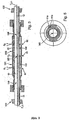
- Fig. 1 is a in a - not shown here - pipeline insertable measuring device for measuring at least one physical measurand - for example, a mass flow, m, a density, p, and / or a viscosity, ⁇ - a run in the pipeline, esp. flowing, fluid shown ,
- the measuring device comprises for this purpose a transducer of the vibration type which is flowed through during operation of the fluid to be measured.
- the transducer serves to generate in a fluid flowing through mechanical reaction forces, eg mass flow-dependent Coriolis forces, density-dependent inertial forces and / or viscosity-dependent frictional forces, the measurable, esp. Sensory detectable, act back on the transducer.
- the mass flow, m, the density, ⁇ , and / or the viscosity, ⁇ , of the fluid can be measured in the manner known to those skilled in the art.
- the mass flow, m, the density, ⁇ , and / or the viscosity, ⁇ of the fluid can be measured in the manner known to those skilled in the art.
- the Fig. 2 to 6 Corresponding embodiments and embodiments of such vibration-type transducers are shown schematically.
- the transducer For guiding the fluid, the transducer comprises a single measuring tube 10 of a predeterminable measuring tube diameter, which is vibrated at least temporarily during operation and thus repeatedly, in particular cyclically, elastically deformed.
- the substantially smooth-walled, circular-cylindrical measuring tube 10 is supported for this purpose in a vibratable manner in a first support member 20 which is fixed in a suitably fixed manner on the inlet side and the outlet side.
- the first support member is tubular, esp. Coaxially aligned with the measuring tube 10, executed;
- the support member 20 may be formed, for example, as a transducer housing enclosing the measuring tube 10 and other components of the transducer.
- a support member 20 may instead of a support tube, for example, a in essential box-shaped support frame serve a. If necessary, but can also substantially along the measuring tube 10 extending support member 20, as well as in the EP-A 518,124 , of the US-A 57 05 754 or the US-A 62 23 605 shown to be formed as a solid support plate or as a box-shaped support frame. Further preferred embodiments of the carrier element 20 as well as other functions thereof will be explained in more detail below.
- a measuring tube 10 which is substantially straight in the process of being shown, it is also possible, in particular in a single plane, in particular S-shaped, for curved tubes, as used in the FIGS Fig.
- measuring tube 10 8 - 10 or eg in the DE-A 39 16 285 or EP-A 518,124 are shown, used as a measuring tube 10.
- An advantage of straight measuring tubes is, for example, that they can be emptied without leaving any residue in virtually any installation position, esp. Even after an in-line cleaning, with high security.
- measuring tubes are compared to a substantially omega-shaped or helically curved measuring tube much easier and therefore cheaper to produce.
- sensors with straight measuring tube usually have a comparison to sensors with curved measuring tube increased sensitivity to temperature fluctuations and concomitant axial length changes.
- measuring tube 10 For flowing the fluid through the measuring tube 10, as in the Fig. 2a . 3 or 8 to 10 shown, connected via an inlet side opening out the first connecting pipe section 11 and via an outlet-side opening second connecting pipe section 12 to the fluid supply and discharge, not shown here, pipeline.
- Measuring tube 10, inlet and outlet pipe section 11, 12 are aligned with each other and aligned to an imaginary longitudinal axis L, advantageously designed in one piece, so that for their production can serve as a single tubular semi-finished; if necessary, measuring tube 10 and pipe sections 11, 12 but also by means of individual, subsequently assembled, eg sixteengesch calendarter, semi-finished products can be produced.
- each of the two connecting pipe pieces 11, 12 is further formed in each case a flange 13 and 14, respectively; if necessary, the connecting pipe pieces 11, 12 but also directly to the pipeline, for example by means of welding or brazing, are connected.
- Fig. 1 In addition to the first support member 20, as well as from the synopsis of Fig. 1 . Fig. 2a and Fig. 3 or even from the Fig. 8 to 10 can be fixed to the connecting pipe pieces 11, 12, a second support member 100, which then, for example, instead of the first support member 20 as the measuring tube 10 receiving transducer housing can be configured, see. Fig. 1 ,
- the measuring tube 10 In operation of the transducer, the measuring tube 10 at least temporarily to bending vibrations, esp. In the range of a momentary natural natural frequency, so excited that in this excited vibration mode, the so-called Nutzmode, at least proportionately Bending oscillations around an inlet end and the outlet end of the measuring tube 10 imaginary connecting vibration axis performs. According to the invention, the measuring tube 10 is thereby excited to such a vibration mode in which it predominantly occupies a first vibration mode with at least three bending anti-vibration bellies. In other words, that natural natural vibration mode with three bending antinodes has the largest share in the instantaneous expression of the excited useful mode or its oscillation form.
- the first mode of vibration of the thus oscillating in the excited vibration mode, so predominantly three or more antinodes having, measuring tube 10 is substantially symmetrical, esp. Rotationally symmetrical, with respect to a direction of action of the excitation force, F exc , imaginary reference axis formed.
- the vibrating measuring tube 10 is deliberately excited so that it predominantly occupies a waveform with exactly three bending antinodes, that is, predominantly oscillates in the so-called f3 mode.
- Coriolis forces are thus induced by means of the measuring tube 10 vibrating in the manner described above in the fluid flowing therethrough. These in turn act on the measuring tube 10 and thus cause an additional, sensory detectable, not shown here, deformation of the measuring tube 10 according to a second waveform, which is coplanar and equal frequency superimposed on the excited Nutzmode of the straight measuring tube 10 here.
- the instantaneous manifestation of the deformation of the measuring tube 10 is, in particular, in terms of their amplitudes, of the instantaneous mass flow, m dependent.
- the so-called Coriolis mode e.g. serve a waveform with four antinodes or symmetrical waveforms with six or more antinodes.
- the transducer further comprises, in particular electrodynamic, exciter 40.
- This serves to one of a, not shown, control electronics fed, electrical excitation energy E exc , eg with a regulated current and / or a regulated Voltage, in one on the measuring tube 10, for example, pulse-shaped or harmonic, acting and this convert elastically deforming exciter force F exc in the manner described above.
- the excitation force F exc can here, as in Fig.
- energizing arrangement 40 for example, a plunger coil arrangement can be used, which has at least one cylindrical excitation coil attached to the measuring tube 10 or first support element 20, which is flowed through by a corresponding excitation current during operation, and a permanent magnet armature, which at least partially plunges into the exciter coil and which is located on the support element 20 on the measuring tube 10 is fixed.
- the exciter assembly 40 also, as in the US-A 45 24 610 shown to be realized by means of one or more electromagnets.
- the exciter assembly 40 such as in the WO-A 99 51 946 shown to realize by means of seismic pathogens.
- the transducer further comprises, in particular electrodynamic, sensor arrangement 50.
- the sensor arrangement 50 can be used, for example, a conventional sensor arrangement for such transducer, in which in the manner known to those skilled in at least one first sensor 51, Preferably, however, by means of a second sensor 52, the movements of the measuring tube 10, in particular on the inlet side and the outlet side, detected and converted into corresponding sensor signals S 1 , S 2 .
- sensors 51, 52 can, for example, as well as in Fig. 5 shown schematically, the vibrations of the measuring tube 10 and counter-oscillator 20 relatively measuring, electrodynamic velocity sensors or electrodynamic displacement sensors or acceleration sensors are used.
- measuring or optoelectronic sensor arrangements for detecting the vibrations of the measuring tube 10 can also be used by means of resistive or piezoelectric strain gauges.
- the sensor signals can be converted into the corresponding measured values in the manner known to the person skilled in the art by means of a corresponding, in particular digital, evaluation electronics.
- Both the above-mentioned control electronics for the exciter arrangement 40 and the evaluation electronics connected to the sensor arrangement 50 can be housed in an electronics housing 200, preferably attached to the converter housing 100.
- the exciter assembly 40 as well as in Fig. 3 and 4 shown, designed and arranged in the transducer so that it simultaneously, esp. Differentially, on measuring tube 10 and counter-oscillator 20 acts.
- the sensor assembly 50 may be designed and arranged in the transducer that the vibrations of measuring tube 10 and counter-oscillator 20 are detected differentially by them.
- the inner part is at least when using a straight measuring tube in an advantageous manner so that it is aligned with the two connecting pipe sections 11, 12 and at least partially within the measuring tube 10 lying first inertial main axis T 1 ; Vibration axis, Meßrohrlijnsachse L and inertial main axis T 1 are otherwise in in Fig. 3 shown embodiment practically coincident. Due to the laying of the center of mass MS of the inner part, esp.
- the operating modes assumed by the measuring tube 10 namely the above-mentioned bending oscillations in Nutz- and Coriolis mode, mechanically largely of possible torsional Vibrations of the measuring tube 10 about the main axis of inertia T 1 decoupled.
- This allows useful bending vibrations and useful torsional vibrations to be excited separately;
- disturbing torsional vibrations can equally effectively be separated from the bending vibrations in the useful and / or Coriolis mode.
- Both the relocation of the center of gravity MS and the first main axis of inertia T 1 toward the measuring tube longitudinal axis L can be considerably simplified, for example, that the inner part, ie measuring tube 10, support member 20 and the attached sensor and exciter assemblies 50, 40, formed and each other are arranged so that a mass distribution of the inner part along the MeßrohrlCodesachse L is substantially symmetrical, but at least invariant with respect to an imaginary rotation about the Meßrohrlticiansachse L by 180 ° (c2 symmetry), is.
- the here tubular, substantially coaxial with the measuring tube 10 arranged support member 20 is also formed largely axially symmetric with respect to the main axis of inertia T 1 , whereby the achievement of a symmetrical mass distribution of the inner part is considerably simplified and thus the center of mass MS in simple way is moved close to the Meßrohrlssensachse L out, see. Fig.
- the sensor and exciter assemblies 50, 40 are advantageously designed and arranged to each other on the measuring tube 10 and optionally on the counter-oscillator 20 that a mass moment of inertia generated by them is formed as concentric with the Meßrohrlssensachse L or at least kept as small as possible. This can be achieved, for example, by the fact that a common center of gravity of the sensor and exciter arrangement 50, 40 is likewise located as close as possible to the measuring tube longitudinal axis L and / or that a total mass of sensor and excitation arrangement 50, 40 is kept as small as possible.
- the exciter assembly 40 is designed for the purpose of separate Anrregung of torsional and / or bending vibrations of the measuring tube 10 or even for active braking of disturbing torsional vibrations and fixed to this and the counteroscillator 20 so that one of the bending vibrations generating force along an imaginary line of force acts on the measuring tube 10, which runs outside of a second inertial main axis T 2 perpendicular to the first main axis of inertia T 1 or intersects the latter in at most one point.
- the inner part is designed so that the second inertial main axis T 2 substantially coincides with the above-mentioned, in the effective direction of the excitation force, F exc , imaginary reference axis, see. Fig. 3 or 4 ,
- the exciter assembly 40 for this purpose at least one at least temporarily by the excitation current or a exciter subcurrent flowing through first exciter coil 41 a, which is fixed to a connected to the measuring tube 10 rigid lever 41 c and fixed on this and one from the outside on the counteroscillator 20 Armature 41 b differentially on the measuring tube 10 and the counteroscillator 20 acts.
- This arrangement also has the advantage that, on the one hand, the counter-oscillator 20 and thus also the transducer housing 100 are kept small in cross-section and nevertheless the exciter coil 41a, esp. Also during assembly, is easily accessible.
- the exciter assembly 40 has at least one arranged along a diameter of the measuring tube 10 second excitation coil 42a in the same manner as the exciter coil 41 a to the measuring tube 10 and the counteroscillator 20 is coupled.
- the exciter arrangement comprises two further excitation coils 43a, 44a, which are symmetrically arranged at least with respect to the second main axis of inertia T 2 , all of which are mounted in the transducer in the aforementioned manner.
- the outside of the second inertial main axis T 2 acting on the measuring tube 10 force can be generated by such two- or four-coil arrangements in a simple manner, for example, characterized in that one of the excitation coils, such as the exciter coil 41 a, a different inductance than the other or that one of the excitation coils, for example, the exciter coil 41 a, is traversed during operation of an exciter subcurrent, which is different from a respective exciter subcurrent of the respective other exciter coils.
- the sensor arrangement 50 comprises, as in Fig. 5 schematically illustrated, outside the second inertial main axis T 2 arranged on the measuring tube 10 fixed sensor coil 51 a.
- the sensor coil 51 a is as close as possible to an armature 51 b fixed to the counteroscillator 20 and magnetically coupled therewith in such a way that in the sensor coil a relative movement between the measuring tube 10 is changed by rotational and / or lateral relative position and / or relative distance and counter-oscillator 20 influenced, variable measuring voltage is induced. Due to the inventive arrangement of the sensor coil 51 a, both the above-mentioned torsional vibrations and the possibly excited bending vibrations can be detected in an advantageous manner at the same time. If necessary, however, the sensor coil 51a can do so also be fixed to the counter-oscillator 20 and in a corresponding manner the coupled thereto anchor 51 b on the measuring tube 10.
- the exciter assembly 40 and the sensor assembly 50 may be performed practically the same in their mechanical structure; Moreover, the aforementioned embodiments of the mechanical structure of the exciter assembly 40 can be transferred substantially to the mechanical structure of the sensor assembly 50 and vice versa.
- a conventional transducer of the type described would serve with a serving as a measuring tube 10 titanium tube having a nominal diameter of 18 mm, a wall thickness of about 1 mm and a length of about 660 mm and filled with water as a medium for the in Fig. 6 schematically shown f3-mode (dashed line) in about an oscillation frequency of 950 ... 1000 Hz and at a vibration amplitude of about 10 microns a resulting transverse force, Q 10 , as well Fig. 7 removable (dashed line), of a total of about 30 N result.
- a coupler arrangement 60 connected to measuring tube 10 and carrier element 20 is provided in the measuring transducer, which at least one with the vibrating measuring tube 10 and the support member 20 mechanically, esp. Spring-elastic, interacting first coupling element 61 comprises.
- the at least one coupling element 61 of the coupler arrangement 60 is in this case is mechanically coupled to the measuring tube 10 and the support member 20 so that it acts in a, esp. Central, area of one of the at least three antinodes on the measuring tube 10.
- the at least one coupling element 61 spring stiffness, c 60 the coupler assembly 60 to the effect.
- the measuring tube 10 is excited by means of the exciter assembly 40 so that the Nutzmode with the bending waveform mentioned above substantially corresponds to a natural eigenmode of the transducer, which essentially determined by the measuring tube 10 and the coupler 60 acting thereon is.
- the measuring tube 10 should oscillate in Nutzmode with a natural natural frequency, which is determined essentially by both the vibration characteristics of the measuring tube 10 with the fluid flowing through and by the vibration characteristics of the acting on the measuring tube 10 coupler assembly 60.
- the coupling element 61 may be, for example, essentially spring-elastic coupling elements with a positive spring constant, ie simple spiral or leaf springs or the like, which are fixed in a suitable manner both on the measuring tube 10 and on the carrier element 20.
- a positive spring constant ie simple spiral or leaf springs or the like
- those coupling elements which have an electrically adjustable negative spring constant, that is to say one or more magnetic coils through which a corresponding direct current flows, at least proportionally. this also the aforementioned US-A 55 31 126 ,
- the above-mentioned exciter arrangement with the exciter coils can simultaneously serve as a coupler arrangement.
- the at least one coupling element 61 is formed as a mechanical spring and, as in the Fig. 4a and 4b shown, also fixed to the one connected to the measuring tube 10 lever 41 c.
- the coupling element is also fixed directly on the counteroscillator.
- the coupling element is formed as a simple, possibly slightly curved in a plane, leaf spring, which is attached to a central portion of the lever 41 c, for example, as in Fig. 2a, b or 4 shown schematically, by soldering in a front side in the lever 41 c molded slot.
- a second, in particular to this substantially identical trained, second coupling element 62 is provided, which also acts in the region of one of the bending-Schwingungsbäuche of the measuring tube on this.
- the two coupling elements are arranged in the transducer so that the coupler assembly 60 is formed at least with respect to the above-mentioned, in the effective direction of the excitation force, F exc , imaginary reference axis is substantially symmetrical.
- the constant ⁇ is about 4000, while it is estimated to be about 600 for gauge tubes bent substantially S-shaped.
- the coupler assembly 60 then at least a 10-fold, using conventional materials and dimensions esp. To about a 20-fold, the Spring stiffness, c 10 , the measuring tube 10 is set.
- the application of the sizing rule in turn causes the spring stiffness, c 60
- the coupler arrangement at least a 0.8 times one in the effective direction of the transverse force, Q 0 , effective spring stiffness, c 10 , of the measuring tube 10 is set.
- the first carrier element 20 also has an effective spring stiffness, c 20 , in the effective direction of the transverse force, Q 0 , which is different from the spring stiffness, c 10 , of the measuring tube 10.
- the spring stiffness, c 10 , of the measuring tube 10 in a further advantageous embodiment of the invention, esp. By at least a 5-fold, lower than the spring stiffness, c 20 , the first support member 20.
- an oscillation frequency of the bending oscillations of the measuring tube 10 is selected so that it is always kept lower during operation, as a lowest mechanical resonance frequency of the support member 20th
- the rigid support member 20 is formed very heavy compared to the measuring tube 10. Accordingly, in this embodiment of the invention, a mass of the first support member 20 is selected so that a total mass of the measuring tube 10 with fluid contained therein is lower than this carrier element mass.
- Another advantage of the invention is also to be seen in the fact that the good results in terms of neutralization of the vibrating tube induced shear forces can surprisingly also be achieved when the measuring tube spanning, rigid first support member 20 and thus the entire sensor very easily are executed.
- the mass of the first support member 20 can also be chosen so that the total mass of the measuring tube 10 with contained therein Fluid is higher than this carrier element mass.
- a rigid and equally lightweight support element can when in Fig. 3 shown embodiment can be achieved in a simple manner, for example by laterally attached to the tubular support member 20 rod or bar-shaped reinforcements extending substantially parallel to the Meßrohrlticiansachse L.
- Another possibility for creating a comparatively lightweight, but also very rigid support member 20 is the use of appropriate materials with a high modulus of elasticity and a low density, such as glass, ceramic, glass ceramic, reinforced with glass and / or carbon fibers plastic or similar.
- the vibration characteristics additionally possibly - simultaneously or alternately - excited useful torsional oscillations around the above-mentioned inlet and outlet end of the measuring tube imaginarily connecting vibration axis, as for example in the case of transducers according to the US-B 68 40 109 can be stimulated, hardly influenced.
- the coupler arrangement 60 according to the invention is preferably to be designed so that a resultant line of action of all the spring forces generated by them substantially with the above-mentioned, in the effective direction of the excitation force, F exc , lying imaginary reference axis coincided.
- the coupler assembly 60 is also to be designed so that a distribution of all the spring forces generated by it is formed substantially symmetrically with respect to the aforesaid reference axis.
Description
Die Erfindung betrifft einen, insb. für eine Verwendung in einem Coriolis-Massedurchflußmesser geeigneten, Meßwandler vom Vibrationstyp.The invention relates to a vibration-type transducer suitable, in particular, for use in a Coriolis mass flowmeter.
Zur Ermittlung eines Massedurchflusses eines in einer Rohrleitung strömenden Fluids, insb. einer Flüssigkeit, werden oftmals solche Meßgeräte verwendet, die mittels eines Meßwandlers vom Vibrationstyp und einer daran angeschlossener Steuer- und Auswerteelektronik, im Fluid Corioliskräfte bewirken und von diesen abgeleitet ein den Massedurchfluß repräsentierendes Meßsignal erzeugen.In order to determine a mass flow rate of a fluid flowing in a pipeline, in particular a liquid, such measuring devices are often used, which cause Coriolis forces in the fluid by means of a transducer of the vibration type and an attached control and evaluation electronics and derived therefrom a measuring signal representing the mass flow produce.
Solche Coriolis-Massedurchflußmesser sind seit langem bekannt und im industriellen Einsatz etabliert. So sind z.B. in der
- ein einziges gebogenes oder gerades, im Betrieb vibrierendes Meßrohr zum Führen des Fluids, welches Meßrohr über ein einlaßseitig einmündendes Einlaßrohrstück und über ein auslaßseitig einmündendes Auslaßrohrstück mit der Rohrleitung kommuniziert,
- ein einlassseitig und auslassseitig am Messrohr fixiertes Trägerelement sowie
- eine Erregeranordnung, die das Meßrohr im Betrieb überwiegend zu Biegeschwingungen in einer Rohrebene anregt, sowie
- eine Sensoranordnung zum punktuellen Erfassen einlaßseitiger und auslaßseitiger Schwingungen des Meßrohrs.
- a single bent or straight, in operation vibrating measuring tube for guiding the fluid, which communicating tube communicates with the pipeline via an inlet tube piece which opens in on the inlet side and via an outlet tube piece which opens out on the outlet side,
- an inlet side and outlet side fixed to the measuring tube carrier element and
- an exciter arrangement, which excites the measuring tube during operation predominantly to bending vibrations in a tube plane, as well as
- a sensor arrangement for the selective detection of inlet-side and outlet-side vibrations of the measuring tube.
Vibrierende Meßrohre von solchen Messaufnehmern bewirken bekanntlich - angeregt zu lateralen Biegeschwingungen um eine das Einlassende und das Auslassende verbindende gedachte Schwingungsachse - im hindurchströmenden Fluid Corioliskräfte. Diese wiederum führen dazu,
daß den angeregten Biegeschwingungen im sogenannten Nutzmode koplanare Biegeschwingungen gemäß einer zweiten Eigenschwingungsform von höherer und/oder niederer Ordnung, dem so genannten Coriolismode, überlagert werden und dementsprechend die mittels der Sensoranordnung einlaßseitig und auslaßseitig erfaßten Schwingungen eine auch vom Massedurchfluß abhängige, meßbare Phasendifferenz aufweisen.Vibrating measuring tubes of such sensors cause known - induced to lateral bending vibrations about an imaginary axis of vibration connecting the inlet end and the outlet end - in the fluid flowing Corioliskräfte. These in turn lead to
that the excited bending oscillations in the so-called Nutzmode coplanar bending oscillations according to a second natural mode of higher and / or lower order, the so-called Coriolis mode superimposed and accordingly have the means of the sensor arrangement on the inlet side and outlet side detected vibrations also dependent on the mass flow, measurable phase difference.
Üblicherweise werden die Meßrohre derartiger, z.B. in Coriolis-Massedurchflußmessern eingesetzten, Meßwandler im Betrieb auf einer momentanen Resonanzfrequenz einer natürlichen Eigenschwingungsform, insb. bei konstantgeregelter Schwingungsamplitude, angeregt. Da diese Resonanzfrequenz insb. auch von der momentanen Dichte des Fluids abhängig ist, kann mittels marktüblicher Coriolis-Massedurchflußmesser neben dem Massedurchfluß auch die Dichte von strömenden Fluiden gemessen werden.Usually, the measuring tubes of such, for example, used in Coriolis mass flow meters, transducers during operation at a momentary resonance frequency of a natural natural vibration form, esp. At constant-controlled oscillation amplitude, excited. Since this resonant frequency is especially dependent on the instantaneous density of the fluid, it is possible by means of commercially available Coriolis mass flowmeters In addition to the mass flow and the density of flowing fluids are measured.
Ein wesentlicher Nachteil vorbeschriebener Meßwandler besteht darin, daß aufgrund wechselseitiger lateraler Auslenkungen des überwiegend im Nutzmode vibrierenden einzigen Meßrohrs gleichfrequent oszillierende Querkräfte auf die Rohrleitung wirken können und daß diese Querkräfte nur mit einem sehr hohen technischen Aufwand von der Dichte des zu messenden Mediums unabhängig kompensiert werden können.A major disadvantage of the above-described transducer is that due to mutual lateral deflections of the predominantly oscillating in Nutzmode single measuring tube gleichfrequent oscillating transverse forces can act on the pipeline and that these shear forces can be compensated independently only with a very high technical complexity of the density of the medium to be measured ,
Zur Verbesserung der dynamischen Balance des Meßwandlers, insb. zur Reduzierung solcher durch das vibrierende einzige Meßrohr erzeugten, einlaßseitig und auslaßseitig auf die Rohrleitung einwirkenden Querkräften, umfassen die in der
Derartige Meßwandler mit Gegenschwinger haben sich insb. bei solchen Anwendungen bewährt, bei denen das zu messende Fluid eine im wesentlich konstante oder nur in einem sehr geringen Maße veränderliche Dichte aufweist, also bei solchen Anwendungen, bei denen eine auf die angeschlossene Rohrleitung wirkende Resultierende aus den vom Meßrohr erzeugten Querkräften und vom Gegenschwinger erzeugten Gegenkräften vorab ohne weiteres auf Null fest eingestellt werden kann.Such transducers with counteroscillators have esp. In such applications proven in which the fluid to be measured has a substantially constant or only to a very small extent variable density, ie in such applications in which acting on the connected pipe resulting from the The lateral forces generated by the measuring tube and the opposing forces generated by the counteroscillator can be set in advance to zero without further ado.
Demgegenüber weist ein derartiger Meßwandler, insb. gemäß der
Weitere Möglichkeiten auch zur dichteunabhängigen Reduzierung solcher Querkräfte sind z.B. in der
Im besonderen ist in der
- ein in den Verlauf der Rohrleitung eingesetztes, im Betrieb zumindest zeitweise vibrierendes Meßrohr zum Führen des Fluids,
- ein an einem Einlassende und an einem Auslassende des Messrohrs fixiertes erstes, insb. gleichfalls vibrierendes, Trägerelement,
- eine elektro-mechanische Erregeranordnung zum Erzeugen einer das Meßrohr virbrienlassenden zeitlich veränderlichen Erregerkraft,
- eine Sensoranordnung zum Erfassen von Schwingungen des Meßrohrs, sowie
- eine mit Messrohr und Trägerelement verbundene Koppleranordnung mit zwei mit dem vibrierenden Messrohr und dem Trägerelement elektro-mechanisch wechselwirkenden Koppelelementen zum Erzeugen von Ausgleichs-Schwingungen,
- wobei das Messrohr im Betrieb mittels der Erregeranordnung zumindest zeitweise zu einem Schwingungsmode angeregt ist,
- -- in dem es solche Biege-Schwingungen um eine das Einlassende und das Auslassende des Messrohrs imaginär verbindende Schwingungsachse ausführt, dass es überwiegend eine Schwingungsform mit einem einzigen Biege-Schwingungsbauch einnimmt, und
- -- in dem es infolge von dabei erzeugten Querkräften zumindest zeitweise aus einer zugewiesenen statischen Ruhelage lateral verschoben ist, und
- wobei die Ausgleichs-Schwingungen der Koppelelemente so ausgebildet und am Messrohr angeordnet sind, daß die erzeugten Querkräfte kompensiert werden und somit ein Massenmittelpunkt eines aus Meßrohr, Erregeranordnung, Sensoranordnung und den beiden Auslegern gebildeten Schwingungssystems ortsfest gehalten wird.
- an inserted in the course of the pipeline, at least temporarily vibrating in operation measuring tube for guiding the fluid,
- a first, in particular likewise vibrating, carrier element fixed at an inlet end and at an outlet end of the measuring tube,
- an electro-mechanical exciter arrangement for generating a time-varying exciter force which allows the measuring tube to travel,
- a sensor arrangement for detecting vibrations of the measuring tube, and
- a coupler arrangement connected to a measuring tube and carrier element with two coupling elements that interact electro-mechanically with the vibrating measuring tube and the carrier element to generate compensating oscillations,
- wherein the measuring tube is excited in operation by means of the excitation arrangement at least temporarily to a vibration mode,
- - In that it performs such bending oscillations around a the inlet end and the outlet end of the measuring tube imaginary connecting axis of oscillation, that it predominantly occupies a vibration mode with a single bending vibrobel, and
- - In which it is laterally displaced as a result of transverse forces generated at least temporarily from an assigned static rest position, and
- wherein the compensating vibrations of the coupling elements are formed and arranged on the measuring tube, that the generated transverse forces are compensated and thus a center of mass of a measuring tube, exciter assembly, sensor assembly and the two arms formed vibration system is held stationary.
Ferner ist in der
- ein in den Verlauf der Rohrleitung eingesetztes, im Betrieb zumindest zeitweise vibrierendes Meßrohr zum Führen des Fluids,
- -- wobei das Meßrohr über ein in das Einlassende einmündendes erstes Verbindungsrohrstück und über ein in das Auslassende einmündendes, mit dem ersten Verbindungsrohrstück und mit der Schwingungsachse fluchtendes zweites Verbindungsrohrstück mit der Rohrleitung kommuniziert,
- ein an einem Einlassende und an einem Auslassende des Messrohrs fixiertes, als gleichfalls vibrierender Gegenschwinger ausgebildetes erstes Trägerelement,
- ein als Wandler-Gehäuse ausgebildetes zweites Trägerelement,
- eine elektro-mechanische Erregeranordnung zum Erzeugen einer das Meßrohr virbrienlassenden zeitlich veränderlichen Erregerkraft,
- eine Sensoranordnung zum Erfassen von Schwingungen des Meßrohrs, sowie
- eine mit Messrohr, den beiden Trägerelementen sowie den Verbindungsrohrstücken verbundene Koppleranordnung mit zwei jeweils am vibrierenden Messrohr, den beiden Trägerelement sowie den Verbindungsrohrstücken fixierten Koppelelementen zum Übertragen von Ausgleichs-Kräften in das Wandlergehäuse,
- wobei das Messrohr im Betrieb mittels der Erregeranordnung zumindest zeitweise zu einem Schwingungsmode angeregt ist,
- -- in dem es solche Biege-Schwingungen um eine das Einlassende und das Auslassende des Messrohrs imaginär verbindende Schwingungsachse ausführt, dass es überwiegend eine Schwingungsform mit einem einzigen Biege-Schwingungsbauch einnimmt,
- wobei die beiden Koppelelemente der Koppleranordnung derart mit dem Messrohr und den Trägerelement mechanisch gekoppelt sind, daß jedes der beiden jeweils in einem Bereich eines gemeinsamen Schwingungsknoten von Messrohr und Gegenschwinger zur Wirkung gelangt, und
- wobei eine durch die Koppelelemente bestimmte, zwischen Messrohr und Wandlergehäuse wirksame, konstante Federsteifigkeit der Koppleranordnung so hoch gewählt ist, daß die Koppleranordnung in einer Wirkrichtung der Querkräfte im wesentlichen als starrer Körper wirkt.
- an inserted in the course of the pipeline, at least temporarily vibrating in operation measuring tube for guiding the fluid,
- wherein the measuring tube communicates with the pipeline via a first connecting tube piece which opens into the inlet end and via a second connecting tube piece which opens into the outlet end and is aligned with the first connecting tube piece and with the oscillation axis,
- a first carrier element fixed at an inlet end and at an outlet end of the measuring tube and also designed as a vibrating counter-oscillator;
- a second carrier element designed as a converter housing,
- an electro-mechanical exciter arrangement for generating a time-varying exciter force which allows the measuring tube to travel,
- a sensor arrangement for detecting vibrations of the measuring tube, and
- a coupled with measuring tube, the two support members and the connecting pipe sections coupler arrangement with two each on the vibrating measuring tube, the two support member and the connecting pipe pieces fixed coupling elements for transmitting balancing forces in the converter housing,
- wherein the measuring tube is excited in operation by means of the excitation arrangement at least temporarily to a vibration mode,
- in which it executes such bending vibrations about an axis of oscillation imaginarily connecting the inlet end and the outlet end of the measuring tube, that it predominantly assumes a vibration mode with a single bending vibration antinode,
- wherein the two coupling elements of the coupler arrangement are mechanically coupled to the measuring tube and the support member such that each of the two in each case in an area of a common node of the measuring tube and counter-oscillator comes into effect, and
- wherein an effective by the coupling elements between the measuring tube and transducer housing, constant spring stiffness of the coupler assembly is chosen so high that the coupler arrangement acts in a direction of action of the transverse forces substantially as a rigid body.
Darüber hinaus ist in der
- ein in den Verlauf der Rohrleitung eingesetztes, im Betrieb zumindest zeitweise vibrierendes Meßrohr zum Führen des Fluids,
- ein an einem Einlassende und an einem Auslassende des Messrohrs fixiertes erstes, insb. gleichfalls vibrierendes, Trägerelement,
- eine elektro-mechanische Erregeranordnung zum Erzeugen einer das Meßrohr virbrienlassenden zeitlich veränderlichen Erregerkraft,
- eine Sensoranordnung zum Erfassen von Schwingungen des Meßrohrs, sowie
- eine mit Messrohr und Trägerelement verbundene Koppleranordnung mit einem mit dem vibrierenden Messrohr und dem Trägerelement elektro-mechanisch wechselwirkenden Koppelelement,
- wobei das Messrohr im Betrieb mittels der Erregeranordnung zumindest zeitweise zu einem Schwingungsmode angeregt ist,
- -- in dem es solche Biege-Schwingungen um eine das Einlassende und das Auslassende des Messrohrs imaginär verbindende Schwingungsachse ausführt, dass es überwiegend eine Schwingungsform mit einem einzigen Biege-Schwingungsbauch einnimmt,
- wobei das eine Koppelelement derart mit dem Messrohr und dem Trägerelement mechanisch gekoppelt ist, daß es in einem zentralen Bereich des einzigen Schwingungsbauchs auf das Messrohr einwirkt, und
- wobei eine durch die Koppelelemente bestimmte, zwischen Messrohr und Trägerelement wirksame, einstellbare Federsteifigkeit der Koppleranordnung negativ ausgebildet ist.
- an inserted in the course of the pipeline, at least temporarily vibrating in operation measuring tube for guiding the fluid,
- a first, in particular likewise vibrating, carrier element fixed at an inlet end and at an outlet end of the measuring tube,
- an electro-mechanical exciter arrangement for generating a time-varying exciter force which allows the measuring tube to travel,
- a sensor arrangement for detecting vibrations of the measuring tube, and
- a coupler arrangement connected to a measuring tube and carrier element with a coupling element interacting electro-mechanically with the vibrating measuring tube and the carrier element,
- wherein the measuring tube is excited in operation by means of the excitation arrangement at least temporarily to a vibration mode,
- in which it executes such bending vibrations about an axis of oscillation imaginarily connecting the inlet end and the outlet end of the measuring tube, that it predominantly assumes a vibration mode with a single bending vibration antinode,
- wherein the one coupling element is mechanically coupled to the measuring tube and the support member such that it acts in a central region of the single antinode on the measuring tube, and
- wherein an effective by the coupling elements, between the measuring tube and support member effective, adjustable spring stiffness of the coupler assembly is formed negative.
Bei vorgenannten Messwandlern wird das Problem von dichteabhängigen Unbalancen im Prinzip dadurch gelöst, daß ein Amplitudengang der Koppelemente oder des Gegenschwingers mittels veränderlicher, von der momentanen Schwingungsamplitude abhängiger Federsteifigkeiten im Betrieb derart an die Meßrohrschwingungen angepaßt wird, daß die vom vibrierenden Meßrohr und Gegenschwinger erzeugten Querkräfte einander teilweise kompensieren. Als Nachteil der vorgeschlagenen Messwandler ist hierbei aber anzusehen, daß trotz technisch jeweils sehr aufwendiger Konstruktionen des Kompensationsmechanismus eine vollständige Neutralisierung der vom Messrohr erzeugten Querkräfte weder praktisch noch theoretisch möglich ist.In the case of the aforementioned transducers, the problem of density-dependent imbalances is in principle solved by adapting an amplitude response of the coupling elements or counter-oscillator to the measuring tube oscillations by means of variable spring stiffnesses dependent on the instantaneous oscillation amplitude such that the transverse forces generated by the vibrating measuring tube and counteroscillator are mutually different partially compensate. However, the disadvantage of the proposed transducer here is to be considered that despite technically very complex designs of the compensation mechanism a complete neutralization of the lateral forces generated by the measuring tube is neither practically nor theoretically possible.
Ein andere Möglichkeit zur Reduzierung von dichteabhängigen Querkräften ist z.B. in der
Darüber hinaus können ferner weitere Störungen von Meßwandlern der beschriebenen Art dadurch auftreten, daß, wie beispielsweise auch in der
Eine Aufgabe der Erfindung besteht daher darin, einen, insb. für einen Coriolis-Massedurchflußmesser oder auch für einen Coriolis-Massedurchfluß/ Dichtemesser geeigneten, Meßwandler vom Vibrationstyp anzugeben, der, auch bei einer Verwendung nur eines einzigen, im Betrieb vom Messrohr durchströmten Meßrohrs, über einen weiten Fluiddichtebereich dynamisch gut ausbalanciert ist und der, insb. auch bei Verwendung Messrohre mit einer Nennweite von größer als 10 mm, trotzdem von vergleichsweise geringer Masse ist.It is therefore an object of the invention to specify a vibration-type transducer suitable in particular for a Coriolis mass flow meter or else for a Coriolis mass flow / density meter which, even if only one single measuring tube flows through the measuring tube during operation, is dynamically balanced well over a wide range of fluid density and which, especially when using measuring tubes with a nominal diameter of greater than 10 mm, is nevertheless of comparatively low mass.
Zur Lösung der Aufgabe besteht die Erfindung in einem Meßwandler vom Vibrationstyp gemäß Anspruch 1 bzw. Anspruch 2.To solve the problem, the invention consists in a transducer of the vibration type according to
Nach einer ersten Ausgestaltung der Erfindung ist das wenigstens eine Koppelelement aufgrund von Relativbewegungen des schwingenden Messrohrs und des Trägerelements wiederholt elastischen Verformungen unterworfen.According to a first embodiment of the invention, the at least one coupling element is repeatedly subjected to elastic deformations due to relative movements of the oscillating measuring tube and the carrier element.
Nach einer zweiten Ausgestaltung der Erfindung verbindet das wenigstens eine Koppelelement Meßrohr und Trägerelement federelastisch miteinander.According to a second embodiment of the invention, the at least one coupling element measuring tube and carrier element connects resiliently together.
Nach einer dritten Ausgestaltung der Erfindung ist das Messrohr, insb. dessen Schwingungsform im angeregten Schwingungsmodes, im wesentlichen symmetrisch, insb. rotationssymmetrisch, bezüglich einer in Wirkrichtung der Erregerkraft liegenden imaginären Bezugsachse ausgebildet.According to a third embodiment of the invention, the measuring tube, in particular its oscillation shape in the excited oscillation mode, is substantially symmetrical, in particular rotationally symmetrical, with respect to an imaginary reference axis lying in the effective direction of the exciter force.
Nach einer vierten Ausgestaltung der Erfindung weist das erste Trägerelement eine gleichfalls in Wirkrichtung der Querkraft wirksame Federsteifigkeit auf, die von der Federsteifigkeit des Messrohrs verschieden ist, insb. ist die Federsteifigkeit des Messrohrs niedriger gewählt als die Federsteifigkeit des ersten Trägerelements.According to a fourth embodiment of the invention, the first support member has an effective also in the effective direction of the transverse force spring stiffness, which is different from the spring stiffness of the measuring tube, esp. The spring stiffness of the measuring tube is chosen lower than the spring stiffness of the first support member.
Nach einer fünften Ausgestaltung der Erfindung ist das erste Trägerelement so ausgebildet, daß seine Masse größer gehalten ist als eine Gesamtmasse von Messrohr mit darin enthaltenem Fluid.According to a fifth embodiment of the invention, the first support member is formed so that its mass is kept larger than a total mass of measuring tube with fluid contained therein.
Nach einer sechsten Ausgestaltung der Erfindung entspricht der angeregte Schwingungsmode im wesentlichen einem natürlichen Eigenmode des Messrohrs mit der darauf einwirkenden Koppleranordnung.According to a sixth embodiment of the invention, the excited oscillation mode essentially corresponds to a natural eigenmode of the measuring tube with the coupler arrangement acting on it.
Nach einer siebenten Ausgestaltung der Erfindung nimmt das vibrierende Messrohr überwiegend eine Schwingungsform mit genau drei Biege-Schwingungsbäuchen ein.According to a seventh embodiment of the invention, the vibrating measuring tube predominantly occupies a vibration mode with exactly three bending antinodes.
Nach einer achten Ausgestaltung der Erfindung ist eine Schwingungsfrequenz der Biege-Schwingungen des Messrohrs im Betrieb stets niedriger gehalten, als eine niedrigste mechanische Resonanzfrequenz des Trägerelements.According to an eighth embodiment of the invention, an oscillation frequency of the bending oscillations of the measuring tube during operation is always kept lower than a lowest mechanical resonance frequency of the carrier element.
Nach einer neunten Ausgestaltung der Erfindung erstreckt sich das erste Trägerelement zumindest abschnittsweise entlang des Messrohrs.According to a ninth embodiment of the invention, the first carrier element extends at least in sections along the measuring tube.
Nach einer zehnten Ausgestaltung der Erfindung ist das Meßrohr zumindest teilweise vom, insb. im wesentlichen rohrförmig ausgebildeten, ersten Trägerelement umhüllt.According to a tenth embodiment of the invention, the measuring tube is at least partially enveloped by, in particular substantially tubular, formed first support member.
Nach einer elften Ausgestaltung der Erfindung sind das Meßrohr und das erste Trägerelement zueinander im wesentlichen koaxial ausgerichtet.According to an eleventh embodiment of the invention, the measuring tube and the first support member are mutually aligned substantially coaxially.
Nach einer zwölften Ausgestaltung der Erfindung kommuniziert das Meßrohr über ein in das Einlassende einmündendes erstes Verbindungsrohrstück und über ein in das Auslassende einmündendes, insb. mit dem ersten Verbindungsrohrstück und/oder mit der Schwingungsachse fluchtendes, zweites Verbindungsrohrstück mit der Rohrleitung.According to a twelfth embodiment of the invention, the measuring tube communicates via a first connecting tube piece which opens into the inlet end and via a second connecting tube piece which leads into the outlet end, in particular aligned with the first connecting tube piece and / or with the oscillation axis.
Nach einer dreizehnten Ausgestaltung der Erfindung ist das erste Trägerelement als einen einlaßseitig und auslaßseitig am Meßrohr fixierter Gegenschwinger ausgebildet und sind das Meßrohr und das erste Trägerelement über das erste und das zweite Verbindungsrohrstück schwingfähig in einem, insb. als Aufnehmer-Gehäuse ausgebildeten, zweiten Trägerelement aufgehängt.According to a thirteenth embodiment of the invention, the first support member is formed as an inlet side and outlet side fixed to the measuring tube counter-oscillator and the measuring tube and the first support member via the first and the second connecting pipe piece vibrationally suspended in a, esp. Designed as a transducer housing, second support member ,
Ein Grundgedanke der Erfindung ist es, einerseits das Messrohr betriebsgemäß in einem Nutzmode vibrieren zu lassen, in dem es eine Schwingungsform einnimmt, die eine ungeradzahlige Anzahl von Schwingungsbäuchen, beispielsweise also drei, fünf oder sieben Schwingungsbäuche u.s.w., aufweist und insoweit im wesentlichen symmetrisch ausgebildet ist. Anderseits zielt die Erfindung darauf ab, mittels in das dergestalt vibrierende Messrohr eingeleiteter Federkräfte die Schwingungsform des im Nutzmode vibrierenden Messrohrs derart zu deformieren, daß nicht nur sämtliche in Richtung der Erregerkraft wirkenden Federkräfte sondern auch möglichst alle resultierend in derselben Richtung wirkenden, vor allem die durch das vibrierende Messrohr hervorgerufenen, Beschleunigungskräfte im Messwandler auch bei schwankender Fluiddichte jeweils weitgehend ausgeglichen, also einander jeweils kompensierend ausgebildet sind. Ein Vorteil der Erfindung besteht dabei darin, daß der Meßwandler zum einen trotz allfälliger, betriebsbedingter Schwankungen der inneren Massenverteilung, z.B. infolge schwankender Fluiddichte, sehr gut ausbalanciert ist, und zwar lediglich aufgrund seiner mittels der Koppleranordnung erzwungenen geometrischen Ausprägung der Biege-Schwingungsform.
Der erfindungsgemäße Meßwandler zeichnet sich des weiteren dadurch aus, daß er zum einen sehr kompakt und zum anderen sehr leicht ausgeführt werden kann. Darüber hinaus kann der erfindungsgemäße Messaufnehmer, insb. aber auch dessen Koppleranordnung mit einem im Vergleich zu herkömmlichen Messaufnehmern der beschriebenen Art nur sehr geringfügigen Mehraufwand gefertigt werden.
Nachfolgend werden die Erfindung und weitere Vorteile anhand eines Ausführungsbeispiels erläutert, das in den Figuren der Zeichnung dargestellt ist. Gleiche Teile sind in den Figuren mit gleichen Bezugszeichen versehen. Falls es der Übersichtlichkeit dienlich ist, wird auf bereits erwähnte Bezugszeichen in nachfolgenden Figuren verzichtet.
-
Fig. 1 zeigt ein in eine Rohrleitung einfügbares Meßgerät zum Messen wenigstens einer physikalischen Meßgröße eines in der Rohrleitung geführten Fluids, -
Fig. 2a zeigt ein Ausführungsbeispiel für einen für das Meßgerät vonFig. 1 geeigneten Meßwandler vom Vibrations-Typ mit einem geraden Messrohr in einer perspektivischen Seitenansicht, -
Fig. 2b zeigt einen vergrößerten Ausschnitt des Messwandlers vonFig. 2a -
Fig. 3 zeigt den Meßwandler vonFig. 2a geschnitten in einer Seitenansicht, -
Fig. 4a zeigt den Meßwandler vonFig. 2a in einem ersten Querschnitt, -
Fig. 4b zeigt den Meßwandler vonFig. 2a in einem zweiten Querschnitt, -
Fig. 5 zeigt den Meßwandler vonFig. 2a in einem dritten Querschnitt, -
Fig. 6 zeigt Biege-Schwingungsformen für vibrierende Messrohre, -
Fig. 7 zeigt den Verlauf von Querkräften, die durch in den Schwingungsformen gemäßFig. 6 vibrierende Messrohre im Messaufnehmer erzeugt werden, und -
Fign. 8 - 10 zeigen weitere Ausführungsbeispiele für einen Meßwandler vom Vibrations-Typ geschnitten in einer Seitenansicht.
The transducer according to the invention is further characterized by the fact that it can be made very compact and very light on the one hand. In addition, the sensor according to the invention, esp. But also its coupler arrangement can be made with a comparison with conventional sensors of the type described only very minor overhead.
Hereinafter, the invention and further advantages will be explained with reference to an embodiment which is illustrated in the figures of the drawing. Identical parts are provided in the figures with the same reference numerals. If it is useful for the sake of clarity, reference numerals already mentioned are omitted in the following figures.
-
Fig. 1 shows a measuring device insertable into a pipeline for measuring at least one physical measurand of a fluid carried in the pipeline, -
Fig. 2a shows an embodiment of a for the meter ofFig. 1 suitable vibration-type transducers with a straight measuring tube in a perspective side view, -
Fig. 2b shows an enlarged section of the transducer ofFig. 2a -
Fig. 3 shows the transducer ofFig. 2a cut in a side view, -
Fig. 4a shows the transducer ofFig. 2a in a first cross section, -
Fig. 4b shows the transducer ofFig. 2a in a second cross section, -
Fig. 5 shows the transducer ofFig. 2a in a third cross section, -
Fig. 6 shows bending vibration modes for vibrating measuring tubes, -
Fig. 7 shows the course of shear forces, by in the waveforms according toFig. 6 Vibrating measuring tubes are generated in the sensor, and -
FIGS. 8 - 10 show further embodiments of a transducer vibrating type cut in a side view.
In der
Zum Führen des Fluids umfaßt Meßwandler ein einziges Meßrohr 10 von vorgebbarem Meßrohrdurchmesser, das im Betrieb zumindest zeitweise vibrieren gelassen und somit wiederholt, insb. zyklisch, elastisch verformt wird. Wie in
Zum Hindurchströmenlassen des Fluids ist das Meßrohr 10, wie in den
Zusätzlich zum ersten Trägerelement 20 kann, wie auch aus der Zusammenschau von
Im Betrieb des Meßwandlers wird das Meßrohr 10 zumindest zeitweise zu Biegeschwingungen, insb. im Bereich einer momentanen natürlichen Eigenfrequenz, so angeregt, daß in diesem angeregten Schwingungsmode, dem so genannten Nutzmode, zumindest anteilig Biege-Schwingungen um eine das Einlassende und das Auslassende des Messrohrs 10 imaginär verbindende Schwingungsachse ausführt. Erfindungsgemäß wird das Messrohr 10 dabei zu einem solchen Schwingungsmode angeregt, in dem es überwiegend eine erste Schwingungsform mit wenigstens drei Biege-Schwingungsbäuchen einnimmt. Anders gesagt hat dann jene natürliche Eigenschwingungsform mit drei Biege-Schwingungsbäuchen den größten Anteil an der momentanen Ausprägung des angeregten Nutzmodes bzw. dessen Schwingungsform. Die erste Schwingungsform des dergestalt im angeregten Schwingungsmode vibrierenden, also überwiegend drei oder mehr Schwingungsbäuche aufweisenden, Meßrohrs 10 ist dabei im wesentlichen symmetrisch, insb. rotationssymmetrisch, bezüglich einer in Wirkrichtung der Erregerkraft, Fexc, liegenden gedachten Bezugsachse ausgebildet. Nach einer vorteilhaften Ausgestaltung der Erfindung wird das vibrierende Messrohr 10 aber gezielt so angeregt, daß es überwiegend eine Schwingungsform mit genau drei Biege-Schwingungsbäuchen einnimmt, also überwiegend im so genannten f3-Mode schwingt.In operation of the transducer, the measuring
Für den Fall, daß das Fluid in der Rohrleitung strömt und somit der Massedurchfluß m von Null verschieden ist, werden so mittels des in oben beschriebener Weise vibrierenden Meßrohrs 10 im hindurchströmenden Fluid Corioliskräfte induziert. Diese wiederum wirken auf das Meßrohr 10 zurück und bewirken so eine zusätzliche, sensorisch erfaßbare, hier jedoch nicht dargestellte, Verformung des Meßrohrs 10 gemäß einer zweiten Schwingungsform, die dem angeregten Nutzmode des hier geraden Messrohrs 10 koplanar und gleichfrequent überlagert ist. Die momentane Ausprägung der Verformung des Meßrohrs 10 ist dabei, insb. hinsichtlich ihrer Amplituden, auch vom momentanen Massedurchfluß, m, abhängig. Als zweite Schwingungsform, dem so genannten Coriolismode, kann z.B. eine Schwingungsform mit vier Schwingungsbäuchen oder auch symmetrische Schwingungsformen mit sechs oder mehr Schwingungsbäuchen dienen.In the event that the fluid flows in the pipeline and thus the mass flow m is different from zero, Coriolis forces are thus induced by means of the measuring
Zum Erzeugen mechanischer Schwingungen des Meßrohrs 10 umfaßt der Meßwandler ferner eine, insb. elektrodynamische, Erregeranordnung 40. Diese dient dazu, eine von einer, hier nicht dargestellten, SteuerElektronik eingespeiste, elektrische Erregerenergie Eexc, z.B. mit einem geregelten Strom und/oder einer geregelten Spannung, in eine auf das Meßrohr 10, z.B. pulsförmig oder harmonisch, einwirkende und dieses in der vorbeschriebenen Weise elastisch verformende Erregerkraft Fexc umzuwandeln. Die Erregerkraft Fexc kann hierbei, wie in
Zum Detektieren von Schwingungen des Meßrohr 10 umfaßt der Meßwandler des weiteren eine, insb. elektrodynamische, Sensoranordnung 50. Als Sensoranordnung 50 kann z.B. eine für derartige Meßwandler übliche Sensoranordnung verwendet werden, bei der in der dem Fachmann bekannten Weise mittels wenigstens eines ersten Sensors 51, vorzugsweise aber auch mittels eines zweiten Sensors 52 die Bewegungen des Meßrohrs 10, insb. einlaßseitig und auslaßseitig, erfaßt und in entsprechende Sensorsignale S1, S2 umgewandelt werden. Als Sensoren 51, 52 können z.B., wie auch in
Nach einer weiteren Ausgestaltung der Erfindung ist die Erregeranordnung 40, wie auch in
Im in
Zudem ist das Innenteil zumindest bei Verwendung eines geraden Messrohrs in vorteilhafter Weise so ausgebildet, daß es eine mit den beiden Verbindungsrohrstücken 11, 12 fluchtende und zumindest abschnittsweise innerhalb des Meßrohrs 10 liegende erste Trägheitshauptachse T1 aufweist; Schwingungsachse, Meßrohrlängsachse L und Trägheitshauptachse T1 sind im übrigen beim in
Nach einer weiteren Ausgestaltung der Erfindung ist das hier rohrförmige, im wesentlichen koaxial zum Meßrohr 10 angeordnete Trägerelement 20 auch weitgehend axial-symmetrisch bezüglich der Trägheitshauptachse T1 ausgebildet, wodurch das Erreichen einer symmetrische Massenverteilung des Innenteils erheblich vereinfacht wird und somit auch der Massenschwerpunkt MS in einfacher Weise nah zur Meßrohrlängsachse L hin verlegt wird, vgl.
Nach einer weiteren Ausgestaltung der Erfindung ist die Erregeranordnung 40 zum Zwecke der getrennten Anrregung von Torsions- und/oder Biegeschwingungen des Meßrohrs 10 oder aber auch zum aktiven Abbremsen von störenden Torsionsschwingungen so ausgebildet und an diesem und am Gegenschwinger 20 so fixiert, daß eine die Biegeschwingungen erzeugende Kraft entlang einer gedachten Kraftlinie auf das Meßrohr 10 wirkt, die außerhalb einer zur ersten Trägheitshauptachse T1 senkrechten zweiten Trägheitshauptachse T2 verläuft oder letztere in höchstens einem Punkt schneidet. Vorzugsweise ist das Innenteil so ausgestaltet, daß die zweite Trägheitshauptachse T2 im wesentlichen mit der oben erwähnten, in der Wirkrichtung der Erregerkraft, Fexc, liegenden gedachten Bezugsachse übereinstimmt, vgl.
Im in der
Nach einer weiteren Ausgestaltung der Erfindung weist die Erregeranordnung 40 wenigstens eine entlang eines Durchmessers des Meßrohrs 10 angeordnete zweite Erregerspule 42a auf die in gleicher Weise wie die Erregerspule 41 a mit dem Meßrohr 10 und dem Gegenschwinger 20 gekoppelt ist. Nach einer Weiterbildung der Erfindung weist die Erregeranordnung zwei weitere, insgesamt also vier zumindest bezüglich der zweiten Trägheitshauptachse T2 symmetrisch angeordnete Erregerspulen 43a, 44a auf, die alle in der vorgenannten Weise im Meßwandler montiert sind.According to a further embodiment of the invention, the
Die außerhalb der zweiten Trägheitshauptachse T2 auf das Meßrohr 10 einwirkende Kraft kann mittels solcher Zwei- oder Vier-Spulen-Anordnungen in einfacher Weise z.B. dadurch erzeugt werden, daß eine der Erregerspulen, z.B. die Erregerspule 41a, eine andere Induktivität aufweist als die jeweils anderen oder daß eine der Erregerspulen, z.B. die Erregerspule 41 a, im Betrieb von einem Erregerteilstrom durchflossen ist, der von einem jeweiligen Erregerteilstrom der jeweils anderen Erregerspulen verschieden ist.The outside of the second inertial main axis T 2 acting on the measuring
Nach einer weiteren Ausgestaltung der Erfindung umfaßt die Sensoranordnung 50, wie in
Es sei hier noch erwähnt, daß falls erforderlich, in der dem Fachmann bekannten Weise, die Erregeranordnung 40 und die Sensoranordnung 50 in ihrem mechanischen Aufbau praktisch auch gleich ausgeführt sein können; überdies lassen sich die vorgenannten Ausgestaltungen des mechanischen Aufbaus der Erregeranordnung 40 im wesentlichen auch auf den mechanischen Aufbau der Sensoranordnung 50 übertragen und umgekehrt.It should be mentioned here that, if necessary, in the manner known to the expert, the
Bei einer Anregung der Biegeschwingungen im Nutzmode werden im in der oben beschriebenen Weise vibrierenden, einzigen Meßrohrs 10 aufgrund von mit den Biegeschwingungen einhergehenden Massenbeschleunigungen bekanntlich entlang des Messrohrs Querkräfte erzeugt. Bei einem in herkömmlicher Weise aufgebauten Innenteil mit einem einfachen, in einem natürlichen symmetrischen Eigenmode schwingenden Messrohr 10 und einem als Gegenschwinger wirkenden ersten Trägerelement ist eine Resultierende vorgenannter Querkräfte bei erheblich schwankender Dichte, p, nicht mehr vernachlässigbar klein. Beispielsweise würden sich bei einem herkömmlichen Meßwandler der beschriebenen Art mit einem als Meßrohr 10 dienenden Titanrohr, das eine Nennweite von 18 mm, eine Wandstärke von etwa 1 mm und eine Länge von etwa 660 mm aufweist und mit Wasser als Medium gefüllt ist, für den in
Für den Fall, daß diese vom vibrierenden Meßrohr 10 verursachte resultierenden Querkraft, Q10 , nicht kompensiert wird, verbleibt ein Querimpuls im Innenteil bzw. im Meßwandler, was wiederum dazu führt, daß das Meßrohr 10 zusammen mit dem daran fixierten ersten Trägerelement 20 lateral aus der zugewiesenen statischen Ruhelage verschoben werden. Dementsprechend würde die Querkraft, Q10 , - hier über die Verbindungsrohrstücke 11, 12 - zumindest teilweise auch auf die angeschlossene Rohrleitung wirken und diese somit gleichfalls vibrieren lassen. Außerdem würden praktisch unvermeidliche mechanische Unsymmetrien im Meßwandler und/oder in der angeschlossenen Rohrleitung zwangsläufig zur Anregung parasitärer asymmetrischer Schwingungsmoden führen, die den Schwingungen des Coriolismodes in nicht mehr ohne weiters separierbarer Weise gleichfrequent überlagert sind. Infolgedessen kann es beispielsweise bei der Messwertgenerierung im besonderen auch zu erheblichen Nullpunktfehlern kommen.In the event that this resulting from the vibrating
Zur Minimierung solcher vom vibrierenden Messrohr generierten, insb. auch auf die Rohrleitung wirkenden und daher für die Messung schädlichen, oszillierenden Querkräfte ist daher im Meßwandler ferner eine mit Messrohr 10 und Trägerelement 20 verbundene Koppleranordnung 60 vorgesehen, die wenigstens ein mit dem vibrierenden Messrohr 10 und dem Trägerelement 20 mechanisch, insb. feder-elastisch, wechselwirkendes erstes Koppelelement 61 umfaßt. Das wenigstens eine Koppelelement 61 der Koppleranordnung 60 ist hierbei derart mit dem Messrohr 10 und dem Trägerelement 20 mechanisch gekoppelt ist, daß es in einem, insb. zentralen, Bereich eines der wenigstens drei Schwingungsbäuche auf das Messrohr 10 einwirkt. Infolgedessen gelangt zwischen Messrohr 10 und Trägerelement 20 auch eine durch das wenigstens eine Koppelelement 61 bestimmte Federsteifigkeit, c60, der Koppleranordnung 60 zur Wirkung.In order to minimize such oscillatory transverse forces generated by the vibrating measuring tube, in particular also acting on the pipeline and therefore detrimental to the measurement, a
Die Wirkung der erfindungsgemäßen Koppleranordnung 60 besteht nunmehr darin, daß die oben erwähnte erste Schwingungsform des Messrohrs 10 mit daran eingreifender Koppleranordnung, wie auch in
Gemäß einer weiteren Ausgestaltung der Erfindung wird das Messrohr 10 mittels der Erregeranordnung 40 so angeregt, daß der Nutzmode mit der oben erwähnten Biege-Schwingungsform im wesentlichen einem natürlichen Eigenmode des Messwandlers entspricht, der im wesentlichen durch das Messrohr 10 und die darauf einwirkende Koppleranordnung 60 bestimmt ist. Anders gesagt, soll das Messrohr 10 im Nutzmode mit einer natürlichen Eigenfrequenz oszillieren, die im wesentlichen sowohl durch die Schwingungseigenschaften des Messrohrs 10 mit dem hindurchströmenden Fluid als auch durch die Schwingungseigenschaften der auf das Messrohr 10 einwirkenden Koppleranordnung 60 bestimmt ist.According to a further embodiment of the invention, the measuring
Bei dem erfindungsgemäßen Koppelelement 61 kann es sich beispielsweise um im wesentlichen federelastisch wirkenden Koppelelemente mit positiver Federkonstante, also einfache Spiral- oder Blattfedern oder dergleichen, handeln, die sowohl am Meßrohr 10 als auch am Trägerelement 20 in geeigneter Weise fixiert sind. Allerdings können auch solche Koppelelemente verwendet werden, die eine elektrisch einstellbare negative Federkonstante aufweisen, also eine oder mehrere zumindest anteilig von einem entsprechenden Gleichstrom durchflossenen Magnetspulen, vgl. hierzu auch die eingangs erwähnte
Nach einer Ausgestaltung der Erfindung ist das wenigstens eine Koppelelement 61 als eine mechanisch Feder ausgebildet und, wie in den
Gemäß einer vorteilhaften Weiterbildung der Erfindung ist in der Koppleranordnung ferner zusätzlich zum ersten Koppelelement 61 ein, insb. zu diesem im wesentlichen baugleich ausgebildetes, zweites Koppelelement 62 vorgesehen, das ebenfalls im Bereich eines der Biege-Schwingungsbäuche des Meßrohrs auf dieses einwirkt. In vorteilhafter Weise sind die beiden Koppelelemente dabei so im Meßwandler angeordnet, daß die Koppleranordnung 60 zumindest bezüglich der oben erwähnten, in Wirkrichtung der Erregerkraft, Fexc, liegenden gedachten Bezugsachse im wesentlichen symmetrisch ausgebildet ist.According to an advantageous embodiment of the invention, in addition to the
Untersuchungen haben ferner ergeben, daß die oben genannten Querkräfte allein mittels der Koppleranordnung weitgehend kompensiert werden können, wenn die durch das wenigstens eine Koppelelement bestimmte und zwischen Messrohr 10 und Trägerelement 20 wirksame Federsteifigkeit, c60, der Koppleranordnung 60 oberhalb des 0,5-fachen eines Verhältnis, Q10 /x0, liegt, das die durch das vibrierende Messrohr 10 einlaßseitig und auslaßseitig in das Trägerelement 20 und/oder in die angeschlossene Rohrleitung insgesamt eingeleitet Querkraft, Q10 , bezogen auf eine laterale Auslenkung, x0 , eines Angriffspunktes repräsentiert, in dem die Koppleranordnung 60 letztlich auf das Messrohr 10 einwirkt. Sehr gute Ergebnisse hinsichtlich der Kompensation der Querkräfte, Q10 , können dabei im besonderen erzielt werden, wenn die Federsteifigkeit, c60, der Koppleranordnung 60 etwa im Bereich des 0,7-fachen bis 1,3-fachen des vorgenannten Verhältnises, Q10 /x0 , liegt ist.Investigations have further shown that the above-mentioned transverse forces can be largely compensated by means of the coupler arrangement, if the determined by the at least one coupling element and effective between measuring
Ferner konnte festgestellt werden, daß - alternativ oder ergänzend zur vorangehenden Dimensionierungsregel - die Federsteifigkeit, c60, der Koppleranordnung 60 für eine zentral am im f3-Mode schwingenden Messrohr 10 angreifende Koppleranordnung basierend auf folgender mathematischen Beziehung ebenfalls sehr leicht ermittelt oder zumindest näherungsweise sehr gut abgeschätzt werden kann:
worin
- α - eine mit einem Eigenwert der Biege-Schwingungsform des angeregten
Nutzmodes korrespondierende, insb. dazu proportionale, Konstante, - E - Elastizitätsmodul (E- oder Young-Modul) des verwendeten Messrohr-Materials,
- J - Flächenträgheitmoment des verwendete Messrohrs und
- I - totale oder "abgewickelte" Länge des Messrohrs oder der Biegelinie sind.
wherein
- α - one with an eigenvalue of the bending mode of the excited
Nutzmodes corresponding, esp. Proportional, constant, - E elastic modulus (E or Young modulus) of the measuring tube material used,
- J - area moment of inertia of the measuring tube used and
- I - total or "unwound" length of the measuring tube or bend line.
Für im wesentlichen gerade Messrohre beträgt die Konstante α etwa 4000, während sie für im wesentlichen S-förmig gebogene Messrohre mit etwa 600 zu veranschlagen ist.For substantially straight gauge tubes, the constant α is about 4000, while it is estimated to be about 600 for gauge tubes bent substantially S-shaped.
Für den Fall, daß das Messrohr 10, wie auch in
Weitere Verbesserungen hinsichtlich der Kompensation der Querkräfte lassen sich ferner dadurch erzielen, daß das erste Trägerelement 20 eine gleichfalls in Wirkrichtung der Querkraft, Q0, wirksame Federsteifigkeit, c20, aufweist, die von der Federsteifigkeit, c10, des Messrohrs 10 verschieden ist. Demgemäß ist die Federsteifigkeit, c10, des Messrohrs 10 in einer weiteren vorteilhaften Ausgestaltung der Erfindung, insb. um wenigstens ein 5-faches, niedriger gewählt als die Federsteifigkeit, c20, des ersten Trägerelements 20. Alternativ oder auch zusätzlich dazu ist nach einer Ausgestaltung der Erfindung eine Schwingungsfrequenz der Biege-Schwingungen des Messrohrs 10 so gewählt, daß sie im Betrieb stets niedriger gehalten ist, als eine niedrigste mechanische Resonanzfrequenz des Trägerelements 20.Further improvements with regard to the compensation of the transverse forces can furthermore be achieved by the fact that the
Nach einer weiteren Ausgestaltung der Erfindung ist das biegesteife Trägerelement 20 im Vergleich zum Messrohr 10 sehr schwer ausgebildet. Demgemäß ist bei dieser Ausgestaltung der Erfindung eine Masse des ersten Trägerelements 20 so gewählt, daß eine Gesamtmasse von Messrohr 10 mit darin enthaltenem Fluid niedriger ist als diese Trägerelement-Masse.According to a further embodiment of the invention, the
Ein weiterer Vorteil der Erfindung ist aber auch darin zu sehen, daß die guten Ergebnisse hinsichtlich der Neutralisierung der vom vibrierenden Messrohr induzierten Querkräfte überraschenderweise auch dann erzielt werden können, wenn das das Messrohr einspannende, biegesteife erste Trägerelement 20 und somit auch der gesamte Messaufnehmer sehr leicht ausgeführt sind.Another advantage of the invention is also to be seen in the fact that the good results in terms of neutralization of the vibrating tube induced shear forces can surprisingly also be achieved when the measuring tube spanning, rigid
Demgemäß kann die Masse des ersten Trägerelements 20 auch so gewählt, daß die Gesamtmasse von Messrohr 10 mit darin enthaltenem Fluid höher ist als diese Trägerelement-Masse. Ein biegesteifes und gleichermaßen leichtes Trägerelement kann beim in
Überdies hat es sich überraschenderweise gezeigt, daß mittels der im Ausführungsbeispiel gezeigten Koppleranordnung 60 mit über den Hebel 41 c jeweils praktisch exzentrisch am Messrohr 10 angreifenden - hier sichelförmig ausgebildeten - Blattfedern nicht nur auch eine sehr wirkungsvolle Verstimmung solcher lateralen Biege-Schwingungsmoden erzielt werden kann, deren Schwingungsrichtung senkrecht zur gemeinsamen Schwingungsrichtung des Nutz- und Coriolismodes verläuft, sondern, daß, insb. auch im Gegensatz zu dem in der
Für den Fachmann besteht im übrigen auch keinerlei Schwierigkeit darin, zu erkennen, daß die erfindungsgemäße Koppleranordnung 60 vorzugsweise so auszubilden ist, daß eine resultierende Wirkungslinie aller durch sie insgesamt erzeugten Federkräfte im wesentlichen mit der oben erwähnten, in Wirkrichtung der Erregerkraft, Fexc, liegenden gedachten Bezugsachse koinzidiert. Darüber hinaus ist die Koppleranordnung 60 für die meisten praktischen Anwendungen auch so auszuführen, daß eine Verteilung aller durch sie insgesamt erzeugten Federkräfte im wesentlichen symmetrisch bezüglich vorgenannter Bezugsachse ausgebildet ist.For the skilled person, moreover, there is no difficulty in recognizing that the
Claims (17)
- Vibronic-type transducer for a fluid flowing through a pipe, said transducer comprising:- a measuring tube (10) inserted in the course of the pipe, and vibrating at least temporarily during operation, designed to conduct the fluid- a first support element (20) fixed at an inlet end and at an outlet end of the measuring tube (10),- an electromagnetic exciter arrangement (40) designed to generate an exciter force, Fexc, which varies over time, to make the measuring tube vibrate (10),- a sensor arrangement (50) designed to measure the vibrations of the measuring tube (10), as well as- a coupler arrangement (60), connected to the measuring tube (10) and support element (20), with at least one coupling element (61) that interacts mechanically, particularly in a spring-elastic manner, with the vibrating measuring tube (10) and the support element (20),- wherein, during operation, the measuring tube (10) is excited to a vibration mode at least temporarily by the exciter arrangement (40), wherein in said mode it at least partially executes such flexural vibrations around an axis of vibration connecting the inlet end and the outlet end of the measuring tube (10) in an imaginary manner that it essentially adopts a vibration form with at least three flexural vibration antinodes,- wherein the at least one coupling element (61) of the coupler arrangement (60) is mechanically coupled to the measuring tube (10) and the support element (20) in such a way that it acts on the measuring tube (10) in an area, particularly a central area, of one of the at least three antinodes,- wherein the measuring tube (10) is essentially straight, and- wherein a spring rigidity, c60, of the coupler arrangement (60), which is determined by the at least one coupling element (61) and acts between the measuring tube (10) and the support element (20), notably an essentially constant spring rigidity, is more than 0.5 times, notably in the range of 0.7 to 1.3 times, a ratio Q10/x0 that represents a transversal force, Q10, which is introduced by the vibrating measuring tube (10) at the inlet side and the outlet side into the carrier element (20) and/or into the connected pipe overall, in relation to a lateral deviation X10 of a point of attack at which the coupler arrangement (60) acts on the measuring tube (10), in such a way that the spring rigidity c60 of the coupler arrangement (60) is set to at least 10 times, notably to around 20 times, a spring rigidity c10 of the measuring tube (10) that acts in the direction of action of the transverse force, Q10, of the measuring tube (10).
- Vibronic-type transducer for a fluid flowing through a pipe, said transducer comprising:- a measuring tube (10) inserted in the course of the pipe, and vibrating at least temporarily during operation, designed to conduct the fluid- a first support element (20) fixed at an inlet end and at an outlet end of the measuring tube (10),- an electromagnetic exciter arrangement (40) designed to generate an exciter force, Fexc, which varies over time, to make the measuring tube vibrate (10),- a sensor arrangement (50) designed to measure the vibrations of the measuring tube (10), as well as- a coupler arrangement (60), connected to the measuring tube (10) and support element (20), with at least one coupling element (61) that interacts mechanically, particularly in a spring-elastic manner, with the vibrating measuring tube (10) and the support element (20),- wherein, during operation, the measuring tube (10) is excited to a vibration mode at least temporarily by the exciter arrangement (40), wherein in said mode it at least partially executes such flexural vibrations around an axis of vibration connecting the inlet end and the outlet end of the measuring tube (10) in an imaginary manner that it essentially adopts a vibration form with at least three flexural vibration antinodes,- wherein the at least one coupling element (61) of the coupler arrangement (60) is mechanically coupled to the measuring tube (10) and the support element (20) in such a way that it acts on the measuring tube (10) in an area, particularly a central area, of one of the at least three antinodes,- wherein the measuring tube (10) is curved, particularly is essentially bent in the shape of an S, and- wherein a spring rigidity, c60, of the coupler arrangement (60), which is determined by the at least one coupling element (61) and acts between the measuring tube (10) and the support element (20), notably an essentially constant spring rigidity, is more than 0.5 times, notably in the range of 0.7 to 1.3 times, a ratio Q10/x0 that represents a transversal force, Q10, which is introduced by the vibrating measuring tube (10) at the inlet side and the outlet side into the carrier element (20) and/or into the connected pipe overall, in relation to a lateral deviation X10 of a point of attack at which the coupler arrangement (60) acts on the measuring tube (10), in such a way that the spring rigidity c60 of the coupler arrangement is set to at least 0.8 times a spring rigidity c10 of the measuring tube (10) that acts in the direction of action of the transverse force, Q10.
- Transducer as claimed in Claim 1 or 2,- wherein, during operation, the measuring tube (10) is excited at least temporarily to a vibration mode in which it at least partially executes torsional vibrations around essentially the same axis of vibration connecting the inlet end and the outlet end of the measuring tube (10) in an imaginary manner, and- wherein the coupling elements (61, 62) are designed as flat springs that are connected to the measuring tube (10) via a lever (41 c).
- Transducer as claimed in one of the previous claims, wherein the at least one coupling element is repeatedly subject, during operation, to elastic deformations due to relative movements of the vibrating measuring tube (10) and the support element (20).
- Transducer as claimed in the previous claim, wherein the at least one coupling element (61) interconnects the measuring tube (10) and the support element (20) in a spring-elastic manner.
- Transducer as claimed in one of the previous claims, wherein the measuring tube (10), notably its vibration form in the excited vibration mode, is essentially symmetrical, particularly rotationally symmetrical, in relation to an imaginary axis of reference located in the direction of action of the exciter force Fexc.
- Transducer as claimed in one of the previous claims, wherein the first support element (20) has a spring rigidity, c20, which also acts in the direction of action of the transversal force, Q10, said rigidity being different to the spring rigidity, c10, of the measuring tube (10).
- Transducer as claimed in the previous claim, wherein the spring rigidity, c10, of the measuring tube (10) is selected as less than the spring rigidity, c20, of the first support element (20).
- Transducer as claimed in one of the previous claims, wherein a total mass of the measuring tube (10), with the fluid it contains, is selected as less than a mass of the first support element.
- Transducer as claimed in one of the previous claims, wherein the excited vibration mode essentially corresponds to a natural eigenmode of the measuring tube (10) with the coupler arrangement (60) acting thereupon.
- Transducer as claimed in the previous claim, wherein the vibrating measuring tube (10) largely adopts a vibration form with precisely three antinodes.
- Transducer as claimed in one of the previous claims, wherein, during operation, a vibration frequency of the flexural vibrations of the measuring tube (10) is always kept lower than a lowest mechanical resonance frequency of the support element (20).
- Transducer as claimed in one of the previous claims, wherein the first support element (20) extends at least in sections along the measuring tube (10).
- Transducer as claimed in the previous claim, wherein the measuring tube (10) is at least partially surrounded by the first support element (20), which particularly is essentially tubular in shape.
- Transducer as claimed in the previous claim, wherein the measuring tube (10) and the first support element (20) are essentially coaxially aligned in relation to one another.
- Transducer as claimed in one of the previous claims, wherein the measuring tube (10) communicates with the pipe via a first connecting tube segment (11) that enters into the inlet end and via a second tube segment (12) that enters into the outlet end, and is particularly aligned with the first connecting tube segment (11) and/or with the axis of vibration.
- Transducer as claimed in the previous claim, wherein the first support element (20) is designed as a counter-vibrator (20') fixed on the measuring tube (10) on the inlet side and outlet side, and wherein the measuring tube and the first support element (20) are suspended in a manner in which they are able to vibrate in a second support element (100), particularly designed as a sensor housing, by means of the first and second connecting tube segment (11, 12).
Applications Claiming Priority (2)
| Application Number | Priority Date | Filing Date | Title |
|---|---|---|---|
| DE200410030392 DE102004030392A1 (en) | 2004-06-23 | 2004-06-23 | Vibration-type transducers |
| PCT/EP2005/052817 WO2006000540A1 (en) | 2004-06-23 | 2005-06-17 | Vibration-type transducer |
Publications (2)
| Publication Number | Publication Date |
|---|---|
| EP1759178A1 EP1759178A1 (en) | 2007-03-07 |
| EP1759178B1 true EP1759178B1 (en) | 2017-08-09 |
Family
ID=35033713
Family Applications (1)
| Application Number | Title | Priority Date | Filing Date |
|---|---|---|---|
| EP05754571.7A Active EP1759178B1 (en) | 2004-06-23 | 2005-06-17 | Vibration-type transducer |
Country Status (4)
| Country | Link |
|---|---|
| EP (1) | EP1759178B1 (en) |
| DE (1) | DE102004030392A1 (en) |
| DK (1) | DK1759178T3 (en) |
| WO (1) | WO2006000540A1 (en) |
Families Citing this family (18)
| Publication number | Priority date | Publication date | Assignee | Title |
|---|---|---|---|---|
| US7475603B2 (en) | 2005-11-15 | 2009-01-13 | Endress + Hauser Flowtec Ag | Measurement transducer of vibration-type |
| US7472607B2 (en) | 2005-11-15 | 2009-01-06 | Endress + Hauser Flowtec Ag | Measurement transducer of vibration type |
| US7490521B2 (en) | 2005-11-15 | 2009-02-17 | Endress + Hauser Flowtec Ag | Measurement transducer of vibration type |
| DE102005054855A1 (en) * | 2005-11-15 | 2007-05-16 | Flowtec Ag | Vibration type fluid measurement transducer has counter oscillator coupled to inlet and outlet sides and balanced extension arms generating flexural torques |
| EP2041167B1 (en) | 2006-07-25 | 2010-05-12 | Lipoxen Technologies Limited | Derivatisation of granulocyte colony-stimulating factor |
| DE102006062220A1 (en) * | 2006-12-22 | 2008-06-26 | Endress + Hauser Flowtec Ag | Vibration-type transducer for use in inline measuring device e.g. Coriolis mass flow rate measuring device, has connecting lines provided for exciter or sensor arrangement, where one line is held at one bracket |
| DE102006062185A1 (en) * | 2006-12-22 | 2008-06-26 | Endress + Hauser Flowtec Ag | Vibration type measuring transducer for use in e.g. coriolis-mass flow measuring device, has connection cables symmetrically shifted relative to axes of tube and inner parts and mirror-symmetrically shifted relative to axes of oscillator |
| DE102006062219A1 (en) * | 2006-12-22 | 2008-06-26 | Endress + Hauser Flowtec Ag | Vibration type measuring transducer for use in e.g. coriolis-mass flow measuring device, has two wired points arranged such that relative distance between points remains unchanged also with vibrating measuring tube |
| DE102007050686A1 (en) | 2007-10-22 | 2009-04-23 | Endress + Hauser Flowtec Ag | Vibration-type transducers |
| DE102007062397A1 (en) * | 2007-12-20 | 2009-06-25 | Endress + Hauser Flowtec Ag | Vibration-type transducers |
| DE102008035877A1 (en) | 2008-08-01 | 2010-02-04 | Endress + Hauser Flowtec Ag | Vibration-type transducers |
| US8316722B2 (en) * | 2009-03-11 | 2012-11-27 | Endress + Hauser Flowtec Ag | Measuring system for media flowing in a pipeline |
| DE102009060834B4 (en) * | 2009-12-29 | 2012-11-29 | Krohne Ag | Coriolis mass flowmeter |
| US9593973B2 (en) | 2012-12-30 | 2017-03-14 | Endress + Hauser Flowtec Ag | Measuring transducer of vibration-type as well as measuring system formed therwith |
| CN105008871B (en) * | 2012-12-30 | 2018-07-31 | 恩德斯+豪斯流量技术股份有限公司 | Transducer of vibration type and the measuring system for being formed with the measurement translator |
| US10188739B2 (en) | 2014-02-27 | 2019-01-29 | Xenetic Biosciences, Inc. | Compositions and methods for administering insulin or insulin-like protein to the brain |
| US20220023430A1 (en) | 2018-11-13 | 2022-01-27 | Lipoxen Technologies Limited | Glycopolysialylation of blinatumomab |
| CN110736454B (en) * | 2019-11-15 | 2024-01-12 | 上海交通大学 | Device and method suitable for angular velocity measurement |
Family Cites Families (9)
| Publication number | Priority date | Publication date | Assignee | Title |
|---|---|---|---|---|
| US4109524A (en) * | 1975-06-30 | 1978-08-29 | S & F Associates | Method and apparatus for mass flow rate measurement |
| ES2232817T3 (en) * | 1995-08-21 | 2005-06-01 | Oval Corporation | CORIOLIS TYPE FLOW METERS. |
| US5979246A (en) * | 1998-02-09 | 1999-11-09 | Micro Motion, Inc. | Spring rate balancing of the flow tube and a balance bar in a straight tube Coriolis flowmeter |
| RU2233432C2 (en) * | 1998-08-31 | 2004-07-27 | Майкро Моушн, Инк. | Coriolis flow meter and method of its exploitation |
| DE19840782C2 (en) * | 1998-09-08 | 2001-09-06 | Krohne Messtechnik Kg | Mass flow meter |
| WO2001027565A1 (en) * | 1999-10-14 | 2001-04-19 | Fmc Corporation | Dynamic counterbalance for coriolis mass flowmeters |
| DE10020606A1 (en) * | 2000-04-27 | 2001-10-31 | Flowtec Ag | Fluid viscosity measuring instrument oscillates measurement tube for generating viscous frictions in fluid |
| US6487917B1 (en) * | 2000-05-02 | 2002-12-03 | Micro Motion, Inc. | Low thermal stress balance bar for a coriolis flowmeter |
| US6666098B2 (en) * | 2001-05-23 | 2003-12-23 | Endress + Hauser Flowtec Ag | Vibratory transducer |
-
2004
- 2004-06-23 DE DE200410030392 patent/DE102004030392A1/en not_active Withdrawn
-
2005
- 2005-06-17 EP EP05754571.7A patent/EP1759178B1/en active Active
- 2005-06-17 DK DK05754571.7T patent/DK1759178T3/en active
- 2005-06-17 WO PCT/EP2005/052817 patent/WO2006000540A1/en active Application Filing
Non-Patent Citations (1)
| Title |
|---|
| None * |
Also Published As
| Publication number | Publication date |
|---|---|
| DE102004030392A1 (en) | 2006-01-19 |
| EP1759178A1 (en) | 2007-03-07 |
| DK1759178T3 (en) | 2017-10-09 |
| WO2006000540A1 (en) | 2006-01-05 |
Similar Documents
| Publication | Publication Date | Title |
|---|---|---|
| EP1759178B1 (en) | Vibration-type transducer | |
| EP1502085B1 (en) | Vibrating measuring transformer | |
| EP2122311B1 (en) | Vibratory transducer | |
| EP1389300B1 (en) | Transducer of the vibration type | |
| EP1381830B1 (en) | Vibration-type measuring transformer | |
| DE102007062397A1 (en) | Vibration-type transducers | |
| DE102008035877A1 (en) | Vibration-type transducers | |
| EP1963793B1 (en) | Vibratory measuring transducer | |
| DE102005062007A1 (en) | Vibration-type measuring transformer used e.g. as a mass flow measuring device comprises a housing, an inner part arranged in the housing, a curved partially vibrating measuring tube and a counter oscillator | |
| DE102005062004A1 (en) | Mass converter housing for use in coriolis mass through-flow measurement has an inner section and a vibrating mass pipe which has greater dead-point stability | |
| DE10235322A1 (en) | Vibration or Coriolis fluid mass flowmeter for measurement of mass flow, and or viscosity, has a single straight measurement pipe and an additional vibrator for generation of a torsional vibration and therefore fluid shear forces | |
| EP1949048B1 (en) | Vibration-type measuring transducer | |
| EP2201337B1 (en) | Measuring transducer of the vibration type | |
| DE10220827A1 (en) | Vibration type fluid mass flow rate transducer has a vibration exciter that also imparts a torsional vibration so that shear flow is introduced making measurements insensitive to fluid viscosity or density variations | |
| DE102006062185A1 (en) | Vibration type measuring transducer for use in e.g. coriolis-mass flow measuring device, has connection cables symmetrically shifted relative to axes of tube and inner parts and mirror-symmetrically shifted relative to axes of oscillator | |
| EP1223412B1 (en) | Coriolis mass flow meter with one curved pipe and with symmetric excitation driver | |
| DE102006062219A1 (en) | Vibration type measuring transducer for use in e.g. coriolis-mass flow measuring device, has two wired points arranged such that relative distance between points remains unchanged also with vibrating measuring tube |
Legal Events
| Date | Code | Title | Description |
|---|---|---|---|
| PUAI | Public reference made under article 153(3) epc to a published international application that has entered the european phase |
Free format text: ORIGINAL CODE: 0009012 |
|
| 17P | Request for examination filed |
Effective date: 20061213 |
|
| AK | Designated contracting states |
Kind code of ref document: A1 Designated state(s): AT BE BG CH CY CZ DE DK EE ES FI FR GB GR HU IE IS IT LI LT LU MC NL PL PT RO SE SI SK TR |
|
| DAX | Request for extension of the european patent (deleted) | ||
| 17Q | First examination report despatched |
Effective date: 20150915 |
|
| GRAP | Despatch of communication of intention to grant a patent |
Free format text: ORIGINAL CODE: EPIDOSNIGR1 |
|
| INTG | Intention to grant announced |
Effective date: 20170216 |
|
| GRAS | Grant fee paid |
Free format text: ORIGINAL CODE: EPIDOSNIGR3 |
|
| GRAA | (expected) grant |
Free format text: ORIGINAL CODE: 0009210 |
|
| AK | Designated contracting states |
Kind code of ref document: B1 Designated state(s): AT BE BG CH CY CZ DE DK EE ES FI FR GB GR HU IE IS IT LI LT LU MC NL PL PT RO SE SI SK TR |
|
| REG | Reference to a national code |
Ref country code: GB Ref legal event code: FG4D Free format text: NOT ENGLISH |
|
| REG | Reference to a national code |
Ref country code: CH Ref legal event code: EP Ref country code: AT Ref legal event code: REF Ref document number: 917346 Country of ref document: AT Kind code of ref document: T Effective date: 20170815 |
|
| REG | Reference to a national code |
Ref country code: IE Ref legal event code: FG4D Free format text: LANGUAGE OF EP DOCUMENT: GERMAN |
|
| REG | Reference to a national code |
Ref country code: DE Ref legal event code: R096 Ref document number: 502005015663 Country of ref document: DE |
|
| REG | Reference to a national code |
Ref country code: DK Ref legal event code: T3 Effective date: 20171003 |
|
| REG | Reference to a national code |
Ref country code: NL Ref legal event code: MP Effective date: 20170809 |
|
| REG | Reference to a national code |
Ref country code: LT Ref legal event code: MG4D |
|
| PG25 | Lapsed in a contracting state [announced via postgrant information from national office to epo] |
Ref country code: LT Free format text: LAPSE BECAUSE OF FAILURE TO SUBMIT A TRANSLATION OF THE DESCRIPTION OR TO PAY THE FEE WITHIN THE PRESCRIBED TIME-LIMIT Effective date: 20170809 Ref country code: NL Free format text: LAPSE BECAUSE OF FAILURE TO SUBMIT A TRANSLATION OF THE DESCRIPTION OR TO PAY THE FEE WITHIN THE PRESCRIBED TIME-LIMIT Effective date: 20170809 Ref country code: FI Free format text: LAPSE BECAUSE OF FAILURE TO SUBMIT A TRANSLATION OF THE DESCRIPTION OR TO PAY THE FEE WITHIN THE PRESCRIBED TIME-LIMIT Effective date: 20170809 Ref country code: SE Free format text: LAPSE BECAUSE OF FAILURE TO SUBMIT A TRANSLATION OF THE DESCRIPTION OR TO PAY THE FEE WITHIN THE PRESCRIBED TIME-LIMIT Effective date: 20170809 |
|
| PG25 | Lapsed in a contracting state [announced via postgrant information from national office to epo] |
Ref country code: PL Free format text: LAPSE BECAUSE OF FAILURE TO SUBMIT A TRANSLATION OF THE DESCRIPTION OR TO PAY THE FEE WITHIN THE PRESCRIBED TIME-LIMIT Effective date: 20170809 Ref country code: BG Free format text: LAPSE BECAUSE OF FAILURE TO SUBMIT A TRANSLATION OF THE DESCRIPTION OR TO PAY THE FEE WITHIN THE PRESCRIBED TIME-LIMIT Effective date: 20171109 Ref country code: GR Free format text: LAPSE BECAUSE OF FAILURE TO SUBMIT A TRANSLATION OF THE DESCRIPTION OR TO PAY THE FEE WITHIN THE PRESCRIBED TIME-LIMIT Effective date: 20171110 Ref country code: IS Free format text: LAPSE BECAUSE OF FAILURE TO SUBMIT A TRANSLATION OF THE DESCRIPTION OR TO PAY THE FEE WITHIN THE PRESCRIBED TIME-LIMIT Effective date: 20171209 Ref country code: ES Free format text: LAPSE BECAUSE OF FAILURE TO SUBMIT A TRANSLATION OF THE DESCRIPTION OR TO PAY THE FEE WITHIN THE PRESCRIBED TIME-LIMIT Effective date: 20170809 |
|
| PG25 | Lapsed in a contracting state [announced via postgrant information from national office to epo] |
Ref country code: CZ Free format text: LAPSE BECAUSE OF FAILURE TO SUBMIT A TRANSLATION OF THE DESCRIPTION OR TO PAY THE FEE WITHIN THE PRESCRIBED TIME-LIMIT Effective date: 20170809 Ref country code: RO Free format text: LAPSE BECAUSE OF FAILURE TO SUBMIT A TRANSLATION OF THE DESCRIPTION OR TO PAY THE FEE WITHIN THE PRESCRIBED TIME-LIMIT Effective date: 20170809 |
|
| REG | Reference to a national code |
Ref country code: DE Ref legal event code: R097 Ref document number: 502005015663 Country of ref document: DE |
|
| PG25 | Lapsed in a contracting state [announced via postgrant information from national office to epo] |
Ref country code: EE Free format text: LAPSE BECAUSE OF FAILURE TO SUBMIT A TRANSLATION OF THE DESCRIPTION OR TO PAY THE FEE WITHIN THE PRESCRIBED TIME-LIMIT Effective date: 20170809 Ref country code: SK Free format text: LAPSE BECAUSE OF FAILURE TO SUBMIT A TRANSLATION OF THE DESCRIPTION OR TO PAY THE FEE WITHIN THE PRESCRIBED TIME-LIMIT Effective date: 20170809 |
|
| PLBE | No opposition filed within time limit |
Free format text: ORIGINAL CODE: 0009261 |
|
| STAA | Information on the status of an ep patent application or granted ep patent |
Free format text: STATUS: NO OPPOSITION FILED WITHIN TIME LIMIT |
|
| REG | Reference to a national code |
Ref country code: FR Ref legal event code: PLFP Year of fee payment: 14 |
|
| 26N | No opposition filed |
Effective date: 20180511 |
|
| PG25 | Lapsed in a contracting state [announced via postgrant information from national office to epo] |
Ref country code: SI Free format text: LAPSE BECAUSE OF FAILURE TO SUBMIT A TRANSLATION OF THE DESCRIPTION OR TO PAY THE FEE WITHIN THE PRESCRIBED TIME-LIMIT Effective date: 20170809 |
|
| REG | Reference to a national code |
Ref country code: CH Ref legal event code: PL |
|
| REG | Reference to a national code |
Ref country code: BE Ref legal event code: MM Effective date: 20180630 |
|
| REG | Reference to a national code |
Ref country code: IE Ref legal event code: MM4A |
|
| PG25 | Lapsed in a contracting state [announced via postgrant information from national office to epo] |
Ref country code: MC Free format text: LAPSE BECAUSE OF FAILURE TO SUBMIT A TRANSLATION OF THE DESCRIPTION OR TO PAY THE FEE WITHIN THE PRESCRIBED TIME-LIMIT Effective date: 20170809 Ref country code: LU Free format text: LAPSE BECAUSE OF NON-PAYMENT OF DUE FEES Effective date: 20180617 |
|
| PG25 | Lapsed in a contracting state [announced via postgrant information from national office to epo] |
Ref country code: LI Free format text: LAPSE BECAUSE OF NON-PAYMENT OF DUE FEES Effective date: 20180630 Ref country code: CH Free format text: LAPSE BECAUSE OF NON-PAYMENT OF DUE FEES Effective date: 20180630 Ref country code: IE Free format text: LAPSE BECAUSE OF NON-PAYMENT OF DUE FEES Effective date: 20180617 |
|
| PG25 | Lapsed in a contracting state [announced via postgrant information from national office to epo] |
Ref country code: BE Free format text: LAPSE BECAUSE OF NON-PAYMENT OF DUE FEES Effective date: 20180630 |
|
| PGFP | Annual fee paid to national office [announced via postgrant information from national office to epo] |
Ref country code: ES Payment date: 20190604 Year of fee payment: 8 |
|
| REG | Reference to a national code |
Ref country code: AT Ref legal event code: MM01 Ref document number: 917346 Country of ref document: AT Kind code of ref document: T Effective date: 20180617 |
|
| PGFP | Annual fee paid to national office [announced via postgrant information from national office to epo] |
Ref country code: FR Payment date: 20190619 Year of fee payment: 15 |
|
| PG25 | Lapsed in a contracting state [announced via postgrant information from national office to epo] |
Ref country code: AT Free format text: LAPSE BECAUSE OF NON-PAYMENT OF DUE FEES Effective date: 20180617 |
|
| PG25 | Lapsed in a contracting state [announced via postgrant information from national office to epo] |
Ref country code: TR Free format text: LAPSE BECAUSE OF FAILURE TO SUBMIT A TRANSLATION OF THE DESCRIPTION OR TO PAY THE FEE WITHIN THE PRESCRIBED TIME-LIMIT Effective date: 20170809 |
|
| PG25 | Lapsed in a contracting state [announced via postgrant information from national office to epo] |
Ref country code: PT Free format text: LAPSE BECAUSE OF FAILURE TO SUBMIT A TRANSLATION OF THE DESCRIPTION OR TO PAY THE FEE WITHIN THE PRESCRIBED TIME-LIMIT Effective date: 20170809 Ref country code: HU Free format text: LAPSE BECAUSE OF FAILURE TO SUBMIT A TRANSLATION OF THE DESCRIPTION OR TO PAY THE FEE WITHIN THE PRESCRIBED TIME-LIMIT; INVALID AB INITIO Effective date: 20050617 |
|
| PG25 | Lapsed in a contracting state [announced via postgrant information from national office to epo] |
Ref country code: CY Free format text: LAPSE BECAUSE OF FAILURE TO SUBMIT A TRANSLATION OF THE DESCRIPTION OR TO PAY THE FEE WITHIN THE PRESCRIBED TIME-LIMIT Effective date: 20170809 |
|
| REG | Reference to a national code |
Ref country code: DK Ref legal event code: EBP Effective date: 20200630 |
|
| PG25 | Lapsed in a contracting state [announced via postgrant information from national office to epo] |
Ref country code: FR Free format text: LAPSE BECAUSE OF NON-PAYMENT OF DUE FEES Effective date: 20200630 |
|
| PGFP | Annual fee paid to national office [announced via postgrant information from national office to epo] |
Ref country code: IT Payment date: 20210625 Year of fee payment: 17 |
|
| PG25 | Lapsed in a contracting state [announced via postgrant information from national office to epo] |
Ref country code: DK Free format text: LAPSE BECAUSE OF NON-PAYMENT OF DUE FEES Effective date: 20200630 |
|
| PGFP | Annual fee paid to national office [announced via postgrant information from national office to epo] |
Ref country code: GB Payment date: 20220622 Year of fee payment: 18 |
|
| P01 | Opt-out of the competence of the unified patent court (upc) registered |
Effective date: 20230601 |
|
| PG25 | Lapsed in a contracting state [announced via postgrant information from national office to epo] |
Ref country code: IT Free format text: LAPSE BECAUSE OF NON-PAYMENT OF DUE FEES Effective date: 20220617 |
|
| PGFP | Annual fee paid to national office [announced via postgrant information from national office to epo] |
Ref country code: DE Payment date: 20230620 Year of fee payment: 19 |
|
| GBPC | Gb: european patent ceased through non-payment of renewal fee |
Effective date: 20230617 |