EP1758693B1 - Compact rolling mill and a method of producing a thin strip - Google Patents
Compact rolling mill and a method of producing a thin strip Download PDFInfo
- Publication number
- EP1758693B1 EP1758693B1 EP05751775.7A EP05751775A EP1758693B1 EP 1758693 B1 EP1758693 B1 EP 1758693B1 EP 05751775 A EP05751775 A EP 05751775A EP 1758693 B1 EP1758693 B1 EP 1758693B1
- Authority
- EP
- European Patent Office
- Prior art keywords
- rings
- roll
- rolling
- rolls
- work roll
- Prior art date
- Legal status (The legal status is an assumption and is not a legal conclusion. Google has not performed a legal analysis and makes no representation as to the accuracy of the status listed.)
- Expired - Lifetime
Links
Images



Classifications
-
- B—PERFORMING OPERATIONS; TRANSPORTING
- B21—MECHANICAL METAL-WORKING WITHOUT ESSENTIALLY REMOVING MATERIAL; PUNCHING METAL
- B21B—ROLLING OF METAL
- B21B31/00—Rolling stand structures; Mounting, adjusting, or interchanging rolls, roll mountings, or stand frames
- B21B31/16—Adjusting or positioning rolls
-
- B—PERFORMING OPERATIONS; TRANSPORTING
- B21—MECHANICAL METAL-WORKING WITHOUT ESSENTIALLY REMOVING MATERIAL; PUNCHING METAL
- B21B—ROLLING OF METAL
- B21B13/00—Metal-rolling stands, i.e. an assembly composed of a stand frame, rolls, and accessories
- B21B13/14—Metal-rolling stands, i.e. an assembly composed of a stand frame, rolls, and accessories having counter-pressure devices acting on rolls to inhibit deflection of same under load; Back-up rolls
-
- B—PERFORMING OPERATIONS; TRANSPORTING
- B21—MECHANICAL METAL-WORKING WITHOUT ESSENTIALLY REMOVING MATERIAL; PUNCHING METAL
- B21B—ROLLING OF METAL
- B21B1/00—Metal-rolling methods or mills for making semi-finished products of solid or profiled cross-section; Sequence of operations in milling trains; Layout of rolling-mill plant, e.g. grouping of stands; Succession of passes or of sectional pass alternations
- B21B1/22—Metal-rolling methods or mills for making semi-finished products of solid or profiled cross-section; Sequence of operations in milling trains; Layout of rolling-mill plant, e.g. grouping of stands; Succession of passes or of sectional pass alternations for rolling plates, strips, bands or sheets of indefinite length
-
- B—PERFORMING OPERATIONS; TRANSPORTING
- B21—MECHANICAL METAL-WORKING WITHOUT ESSENTIALLY REMOVING MATERIAL; PUNCHING METAL
- B21B—ROLLING OF METAL
- B21B27/00—Rolls, roll alloys or roll fabrication; Lubricating, cooling or heating rolls while in use
- B21B27/02—Shape or construction of rolls
- B21B27/021—Rolls for sheets or strips
- B21B2027/022—Rolls having tapered ends
-
- B—PERFORMING OPERATIONS; TRANSPORTING
- B21—MECHANICAL METAL-WORKING WITHOUT ESSENTIALLY REMOVING MATERIAL; PUNCHING METAL
- B21B—ROLLING OF METAL
- B21B2271/00—Mill stand parameters
- B21B2271/02—Roll gap, screw-down position, draft position
-
- B—PERFORMING OPERATIONS; TRANSPORTING
- B21—MECHANICAL METAL-WORKING WITHOUT ESSENTIALLY REMOVING MATERIAL; PUNCHING METAL
- B21B—ROLLING OF METAL
- B21B29/00—Counter-pressure devices acting on rolls to inhibit deflection of same under load, e.g. backing rolls ; Roll bending devices, e.g. hydraulic actuators acting on roll shaft ends
-
- B—PERFORMING OPERATIONS; TRANSPORTING
- B21—MECHANICAL METAL-WORKING WITHOUT ESSENTIALLY REMOVING MATERIAL; PUNCHING METAL
- B21B—ROLLING OF METAL
- B21B31/00—Rolling stand structures; Mounting, adjusting, or interchanging rolls, roll mountings, or stand frames
- B21B31/16—Adjusting or positioning rolls
- B21B31/18—Adjusting or positioning rolls by moving rolls axially
Definitions
- This invention relates in general to mills for rolling metal products such as strands and strips. More specifically, it relates to an apparatus for rolling a narrow strip and a method of producing a thin strip according to the preamble of claims 1 and 5 (see, for example, GB 523 777 ).
- Rolling mills are used for reducing the thickness of metal strips.
- the simplest rolling mill is constructed with two large and heavy work rolls rotating in opposite directions and forming a nip in between.
- the mill is called 2-high mill.
- the term "nip" is used herein to refer to the region where the rolls are closest together.
- the high forces associated with the rolling are guided to the work rolls bearings, which therefore have to be strong, that are heavily build.
- work rolls bearings For rolling thin strips it is for contrary necessary to use work rolls with small diameter. However, with small rolls there is not enough space for strong bearings, which are required due high rolling forces. This had led to various roll arrangements in rolling mills for thin strips.
- the arrangements conventionally comprises two small diameter work rolls and several support rolls, which are carrying the rolling forces and directing them through the bearings to the rolling mill frame.
- the work rolls are at least supported by backup rolls and sometimes with a system of intermediate rolls and backup rolls.
- the system comprising two work rolls and two backup rolls is the most common arrangement for rolling thin strips. It is called 4-high construction.
- the work rolls of such construction are kept in place with small bearings whereas the rolling force is carried by support/backup rolls fitted to big heavy-duty bearings in mill frame.
- 4-high rolling mills are quite useful for producing the thin strip but the problem is that the heavy backup rolls are requiring a big and solid frame.
- the overall size of the frame of such rolling mill can be 2 to 3 meters high.
- FR2257360 A1 discloses an apparatus for rolling a strip.
- the apparatus comprises work rolls and intermediate rolls that form a gap and a ring that acts on the work rolls.
- the gap is adjusted by displacing the intermediate rolls.
- GB523777 A discloses an apparatus for rolling a strip.
- the apparatus comprises work rolls that form a gap and two rings that act on the work rolls.
- the gap is adjusted by displacing one of the intermediate rolls.
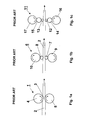
- Fig. 1a to 1c are presented three prior art configurations of the rolling mill.
- Fig. 1 a is a simple 2-high mill 1, where the strip 2 is guided directly to the nip 3 of two massive work rolls 4 and 5.
- This configuration is not suitable for rolling a thin strip since for rolling a thin strip two small work rolls are needed.
- the work rolls 4 and 5 are connected to the mill frame with strong roll bearings. The bearings and the mill frame are not shown in the Fig. 1 a.
- Fig. 1b is the most common arrangement, which is called a 4-high mill 6.
- the smaller work rolls 7 and 8 transfer the rolling forces to the support/backup rolls 9 and 10, which again are connected to the mill frame with strong roll bearings.
- This configuration is suitable for rolling a thin strip 2, but the mill frame is still very massive as it was also with 2-high mill 1.
- Fig. 1c is a third arrangement 11 with two small work rolls 12 and 13, two bigger intermediate rolls 14 and 15 and two big support/backup rolls 16 and 17.
- the bearings with the small work rolls 12 and 13 can be made lighter as also in with the 4-high mill 6 but nevertheless the big support/backup rolls 16 and 17 need to be connected to the mill frame with strong roll bearings.
- This arrangement 11 needs also very massive mill frame.
- Fig. 2 is a schematic side view presentation of the main components of the rolling mill 18.
- the apparatus comprises two rings 19 and 20, which are arranged parallel to each other and each on opposite sides of the strip 21.
- the second ring 20 is positioned behind the first ring 19 and cannot be seen.
- the inner surface 22 and the outer surface 23 of the rings 19 and 20 are essentially flat and parallel to the rolling axes of the rings.
- a second work roll 25 is arranged inside the rings 19 and 20 to form a nip 26 between the work rolls 24 and 25, where the actual rolling of the strip 21 is done.
- the actual length of the second work 25 roll does not actually have to extend inside the rings 19 and 20. It is enough that the imaginary extension of the work roll 25 does it.
- the second work roll 25 is in that case situated between the two rings 19 and 20. Further inside the rings 19 and 20 are arranged first and second intermediate rolls 27 and 28. The purpose of these intermediate rolls 27 and 28 is to change the rolling direction 29 of the second work roll 25 and on the other hand made possible to adjust the gap in the nip 26. The adjustment of the gap in the nip 26 is explained in more details later on in Fig. 6 .
- the inner surfaces 22 of the rings 19 and 20 can alternatively be made slightly concave and the surfaces of the rolls 24, 25, 27 and 28 can be also contoured to match the inner surfaces 22. The reason is that there might be a need to skew the mill 18 a little to get the strip 21 straight and to keep the strip from moving sideways.
- Fig. 3 which is a cross-section along line A-A from Fig. 2
- the surrounding rings 19 and 20 are forming four rectangular cross-sectional areas in the top and bottom of the drawing due the parallel inner and outer surfaces 22 and 23 of the rings in relation with the rolling axes of the rings.
- the cross-sectional area of the rings 19 and 20 can be anything. The only limiting factor is the inner surface 22 of the rings 19 and 20, which must be essentially flat (but not even parallel to the rolling axes of the rings as is explained later).
- the first work roll 24, which penetrates through both rings 19 and 20, has bearings 35 in both ends.
- the bearings 35 are mounted in the support structure (the mill frame), which is not shown in the drawing.
- the second work roll 25 is rotating freely and supported by the two intermediate rolls 27 and 28 and has no bearings in its ends.
- the second work roll 25 can be made also shorter so that it is not reaching the insides of the rings 19 or 20 but is situated in between them.
- the contact between the rings 19 and 20 and the first work roll 24 together with the contact between the rings 19 and 20 and two intermediate rolls 27 and 28 are keeping the assembly together.
- the rings 19 and 20 are taking the large amount of the rolling forces the bearings 35 and 36 associated with the first work roll 24 and intermediate rolls 27 and 28 can be made very light. This reduces the size of the whole rolling mill arrangement 18 significantly.
- the arrangement in the rolling mill 18 can be made also with only one ring 19 or 20 situated in the middle of the rolling mill. With this construction it is possible to roll one or two strips 21 at the same time in one mill 18. In case of two strips the strips are situated to the opposite sides of the ring 19 or 20.
- the rings can be arranged inside a stationary frame 37. Between the frame 37 and rings 19 and 20 (ring 20 behind ring 19) are arranged a number of bearing rolls 38. With this arrangement the rolling movement of the rings 19 and 20 can be covered and the frame 37 is maintained stationary.
- the outer design of the frame 37 can be whatever the manufacturer decides.
- the frame 37 is presented in rectangular form.
- the bearing assembly can be any conventional bearing assembly.
- Fig. 5 is presented another way of arranging the work rolls 24 and 25 inside the rings 19 and 20.
- only one intermediate roll 39 is arranged between the second work roll 25 and the rings 19 and 20 to change the rolling direction of the work roll and to support the work roll.
- the second work roll 25 is also mounted to the mill frame with bearings.
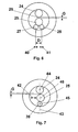
- Fig. 7 is illustrated the control of the gap G for the arrangement presented in Fig. 5 .
- the second work roll 25 can be moved according the arrow 42 in relation to the line 43, which is drawn between the rolling axes 44 and 45 of the first work roll 24 and the intermediate roll 39. Moving the second work rolls 25 rolling axis 46 further from the line 43 the gap G in the nip 26 is increased and when moved towards the line the gap in the nip is diminished. The same effect can be achieved with the movement of the intermediate roll 39 as well.
- the reference line is drawn between the rolling axes 44 and 46 of the first work roll and the second work roll.
- Fig. 8 is presented a solution, according to the present invention, for the control of the gap G.
- This solution is suitable to all presented arrangement of the rolling mills in Figures 2 to 7 .
- the ends of the first work roll 24 and the intermediate roll(s) 27 (and 28) are tapered forming contact surfaces 47 and 48 with the rings 19 and 20.
- the inner surfaces 22 of the rings 19 and 20 are tapered correspondingly.
- the rolling mill frame structure can be made significantly smaller. This is due the smaller bearings needed for the rolls in the rolling mill.
Landscapes
- Engineering & Computer Science (AREA)
- Mechanical Engineering (AREA)
- Metal Rolling (AREA)
- Reduction Rolling/Reduction Stand/Operation Of Reduction Machine (AREA)
- Rolling Contact Bearings (AREA)
Description
- This invention relates in general to mills for rolling metal products such as strands and strips. More specifically, it relates to an apparatus for rolling a narrow strip and a method of producing a thin strip according to the preamble of
claims 1 and 5 (see, for example,GB 523 777 - Rolling mills are used for reducing the thickness of metal strips. The simplest rolling mill is constructed with two large and heavy work rolls rotating in opposite directions and forming a nip in between. The mill is called 2-high mill. The term "nip" is used herein to refer to the region where the rolls are closest together. The high forces associated with the rolling are guided to the work rolls bearings, which therefore have to be strong, that are heavily build. For rolling thin strips it is for contrary necessary to use work rolls with small diameter. However, with small rolls there is not enough space for strong bearings, which are required due high rolling forces. This had led to various roll arrangements in rolling mills for thin strips.
- For rolling thin strips the arrangements conventionally comprises two small diameter work rolls and several support rolls, which are carrying the rolling forces and directing them through the bearings to the rolling mill frame. Usually the work rolls are at least supported by backup rolls and sometimes with a system of intermediate rolls and backup rolls. The system comprising two work rolls and two backup rolls is the most common arrangement for rolling thin strips. It is called 4-high construction. The work rolls of such construction are kept in place with small bearings whereas the rolling force is carried by support/backup rolls fitted to big heavy-duty bearings in mill frame.
- 4-high rolling mills are quite useful for producing the thin strip but the problem is that the heavy backup rolls are requiring a big and solid frame. The overall size of the frame of such rolling mill can be 2 to 3 meters high. The main
- disadvantage of such mills is that also for narrow strips the rolling mill becomes big and expensive.
- Above described rolling mills are disclosed for example in following documents.
US 2003/0167818 A1 discloses a hot rolling mill where a thin steel strip is passed through work rolls, which are supported by backing rolls. The construction is typical 4-high rolling mill. Such a 4-high rolling mill constructions is disclosed also inUS 2002/0043358 A1 . - In
US 2001/0018840 are disclosed a construction with small work rolls, bigger intermediate rolls and large backup rolls. With such construction the size of the frame becomes even bigger than with 4-high rolling mill. -
FR2257360 A1 -
GB523777 A - The object of this invention is to provide an apparatus having a compact and low cost construction and also a new method for rolling a thin strip. Another object of this invention is to produce an apparatus and method for an easy adjustment of the gap in the nip.
- These above mentioned objects are achieved by an apparatus and a method described later in the
independent claims - The invention is described in more details referring to following drawings, where
-
Fig.1a to 1c are simplified pictures of three prior art rolling mills, -
Fig. 2 is a schematic side view presentation of the main components of the rolling mill not covered by the invention, -
Fig. 3 is a cross-sectional view according to line A-A fromFig. 2 , -
Fig. 4 is a schematic side view presentation of the main components of the rolling mill the invention, -
Fig. 5 is a schematic side view presentation of the main components of the rolling mill the invention, and -
Figs. 6 to 8 are schematic side view presentations of the adjustment of the gap in the nip of the rolling mill according to the invention. - In
Fig. 1a to 1c are presented three prior art configurations of the rolling mill. InFig. 1 a is a simple 2-high mill 1, where thestrip 2 is guided directly to thenip 3 of twomassive work rolls Fig. 1 a. - In
Fig. 1b is the most common arrangement, which is called a 4-high mill 6. There thesmaller work rolls backup rolls thin strip 2, but the mill frame is still very massive as it was also with 2-high mill 1. - In
Fig. 1c is athird arrangement 11 with twosmall work rolls intermediate rolls backup rolls small work rolls high mill 6 but nevertheless the big support/backup rolls arrangement 11 needs also very massive mill frame. - The requirement for strong bearings in all three
prior art solutions - In
Fig. 2 is a schematic side view presentation of the main components of therolling mill 18. The apparatus comprises tworings strip 21. In this view thesecond ring 20 is positioned behind thefirst ring 19 and cannot be seen. In this embodiment theinner surface 22 and theouter surface 23 of therings rings inner surfaces 22 of therings second work roll 25 is arranged inside therings strip 21 is done. The actual length of thesecond work 25 roll does not actually have to extend inside therings work roll 25 does it. Thesecond work roll 25 is in that case situated between the tworings rings intermediate rolls intermediate rolls direction 29 of thesecond work roll 25 and on the other hand made possible to adjust the gap in thenip 26. The adjustment of the gap in thenip 26 is explained in more details later on inFig. 6 . - The
inner surfaces 22 of therings rolls strip 21 straight and to keep the strip from moving sideways. - When the strip is moving to the direction of the
arrow 30 thefirst work roll 24 is rotating accordingarrow 31,lower work roll 25 according toarrow 29, theintermediate rolls arrows rings arrow 34. Therings rolls Fig. 1 . - In
Fig. 3 , which is a cross-section along line A-A fromFig. 2 , the surroundingrings outer surfaces rings inner surface 22 of therings first work roll 24, which penetrates through bothrings bearings 35 in both ends. Thebearings 35 are mounted in the support structure (the mill frame), which is not shown in the drawing. At the same way the twointermediate rolls bearings 36 to the support structure. Thesecond work roll 25 is rotating freely and supported by the twointermediate rolls second work roll 25 can be made also shorter so that it is not reaching the insides of therings rings first work roll 24 together with the contact between therings intermediate rolls rings bearings first work roll 24 andintermediate rolls rolling mill arrangement 18 significantly. - The arrangement in the rolling
mill 18 can be made also with only onering strips 21 at the same time in onemill 18. In case of two strips the strips are situated to the opposite sides of thering - In
Fig. 4 , the rolling movements of therings stationary frame 37. Between theframe 37 and rings 19 and 20 (ring 20 behind ring 19) are arranged a number of bearing rolls 38. With this arrangement the rolling movement of therings frame 37 is maintained stationary. The outer design of theframe 37 can be whatever the manufacturer decides. Here theframe 37 is presented in rectangular form. Also the bearing assembly can be any conventional bearing assembly. - In
Fig. 5 is presented another way of arranging the work rolls 24 and 25 inside therings intermediate roll 39 is arranged between thesecond work roll 25 and therings second work roll 25 is also mounted to the mill frame with bearings. - It is important to be able to adjust the gap G in the
nip 26 for variations in the strip thickness. This is achieved inFig. 3 with movement of theintermediate rolls Fig. 6 witharrows rolls second work roll 25 can move further from thefirst work roll 24 and the gap G in thenip 26 is increased. On the other hand, when the distance D between theintermediate rolls second work roll 25 is forced to move towards thefirst work roll 24 and the gap G in thenip 26 is diminished. The variation in the distance D can be achieved by moving either one of theintermediate rolls intermediate rolls nip 26. Also the adjustment of the gap G can be done with a combination of any of these methods. - In
Fig. 7 is illustrated the control of the gap G for the arrangement presented inFig. 5 . Thesecond work roll 25 can be moved according thearrow 42 in relation to theline 43, which is drawn between the rollingaxes first work roll 24 and theintermediate roll 39. Moving the second work rolls 25 rollingaxis 46 further from theline 43 the gap G in thenip 26 is increased and when moved towards the line the gap in the nip is diminished. The same effect can be achieved with the movement of theintermediate roll 39 as well. In this case the reference line is drawn between the rollingaxes - In
Fig. 8 is presented a solution, according to the present invention, for the control of the gap G. This solution is suitable to all presented arrangement of the rolling mills inFigures 2 to 7 . The ends of thefirst work roll 24 and the intermediate roll(s) 27 (and 28) are tapered forming contact surfaces 47 and 48 with therings inner surfaces 22 of therings rings rings arrow 49. - With the above-described embodiments of the invention the rolling mill frame structure can be made significantly smaller. This is due the smaller bearings needed for the rolls in the rolling mill.
- While the invention has been described with reference to its preferred embodiments, it is to be understood that modifications and variations will occur to those skilled in the art. Such modifications and variations are intended to fall within the scope of the appended claims.
Claims (10)
- An apparatus for rolling a strip (21) comprising a first work roll (24), which is mounted from both ends with bearings (35) to the mill frame, a second work roll (25), which work rolls (24, 25) are forming a nip (26) in between them, at least two rings (19, 20) closing inside at least the first work roll (24) at the opposite ends of the roll (24), at least first intermediate roll (27, 39) mounted to the mill frame from both ends with bearings (36) and arranged in rolling contact and between the second work roll (25) and inside surfaces (22) of the rings (19, 20). characterized in that the first work roll (24) and the intermediate roll(s) (27, 28, 39) are tapered at both ends and the insides surfaces (48) of the rings (19, 20) are also tapered accordingly.
- An apparatus according to claim 1 wherein the apparatus further comprises a second intermediate roll (28) mounted to the mill frame from both ends with bearings (36) and arranged in rolling contact and between the second work roll (25) and the inside surfaces (22) of the rings (19, 20)
- An apparatus according to claim 1 or 2 wherein the apparatus further comprises stationary frame (37) arranged to cover the outside surfaces (23) of the rings (19, 20) and where in between the frame (37) and the rings (19, 20) are arranged a bearing assembly (38).
- An apparatus according to any of the claims 1 to 3 wherein the surfaces of the work rolls (24, 25), the intermediate roll(s) (27, 28, 39) and the inside surfaces (22) of the rings (19, 20) are essentially flat and parallel to the rolling axes of the rings (19, 20).
- A method for rolling a strip (21) comprising the steps of:- mounting a first work roll (24) from both ends to the mill frame with bearings (35)- arranging a second work roll (25) so that they form a nip (26) in between arranging at least two rings (19, 20) to close inside at least the first work roll (24)- arranging a first intermediate roll (27, 39) mounted from both ends to the mill frame in rolling contact with the second work roll (25) and the inside surfaces (22) of the rings (19, 20)- wherein the first work roll (24) and the intermediate roll(s) (27, 28, 39) are tapered at both ends and the inside surfaces (48) of the rings (19, 20) are tapered accordingly- directing the strip (21) to the nip (26)- adjusting the gap (G) in the nip (26) by changing the distance (D) between the rings (19, 20).
- A method according to claim 5 wherein the method further comprises the step of:- arranging a second intermediate roll (28) between the second work roll (25) and the inside surfaces (22) of the rings (19, 20) and mounting the second intermediate roll (28) from both ends to the mill frame with bearings (36).
- A method according to any of claims 5 to 6 wherein the adjustment of the gap (G) in the nip (26) is done by moving one of the intermediate rolls (27, 28, 39).
- A method according to claim 11 or 13 wherein the adjustment of the gap (G) in the nip (26) is done by moving both intermediate rolls (27, 28) into the opposite directions or into the same direction.
- A method according to claim 5 wherein the adjustment of the gap (G) in the nip (26) is done by moving the second work roll (25) in relation to the line (43) drawn between the rolling axes (44, 45) of the first work roll (24) and the first intermediate roll (27, 39).
so that the - A method according to any of claims 5 to 9 wherein the method further comprises the step of:- covering the ring(s) (19, 20) with stationary frame (37) and arranging a bearing assembly (38) between the stationary frame (37) and the ring(s) (19, 20).
Applications Claiming Priority (2)
| Application Number | Priority Date | Filing Date | Title |
|---|---|---|---|
| US10/870,210 US7131307B2 (en) | 2004-06-17 | 2004-06-17 | Compact rolling mill and a method of producing a thin strip |
| PCT/FI2005/000275 WO2005123290A1 (en) | 2004-06-17 | 2005-06-14 | Compact rolling mill and a method of producing a thin strip |
Publications (3)
| Publication Number | Publication Date |
|---|---|
| EP1758693A1 EP1758693A1 (en) | 2007-03-07 |
| EP1758693A4 EP1758693A4 (en) | 2011-05-04 |
| EP1758693B1 true EP1758693B1 (en) | 2013-09-18 |
Family
ID=35479178
Family Applications (1)
| Application Number | Title | Priority Date | Filing Date |
|---|---|---|---|
| EP05751775.7A Expired - Lifetime EP1758693B1 (en) | 2004-06-17 | 2005-06-14 | Compact rolling mill and a method of producing a thin strip |
Country Status (5)
| Country | Link |
|---|---|
| US (1) | US7131307B2 (en) |
| EP (1) | EP1758693B1 (en) |
| CN (1) | CN100515590C (en) |
| MY (1) | MY146332A (en) |
| WO (1) | WO2005123290A1 (en) |
Families Citing this family (1)
| Publication number | Priority date | Publication date | Assignee | Title |
|---|---|---|---|---|
| CN102294355B (en) * | 2011-08-19 | 2013-11-06 | 江汉大学 | Device for rolling and forming section of thin-wall ring component |
Family Cites Families (12)
| Publication number | Priority date | Publication date | Assignee | Title |
|---|---|---|---|---|
| US18840A (en) * | 1857-12-15 | Improvement in cultivators | ||
| US167818A (en) * | 1875-09-21 | Improvement in trusses | ||
| BE370727A (en) * | 1926-03-05 | |||
| US1908268A (en) * | 1931-08-19 | 1933-05-09 | Skf Svenska Kullagerfab Ab | Rolling mill |
| US1908269A (en) * | 1931-08-19 | 1933-05-09 | Skf Svenska Kullagerfab Ab | Rolling mill |
| GB523777A (en) * | 1938-12-14 | 1940-07-23 | Robert Bass | Rolling-mills |
| CH326239A (en) * | 1955-02-14 | 1957-12-15 | Zueblin Julius | Rolling mill |
| FR1570660A (en) * | 1968-04-12 | 1969-06-13 | ||
| FR2257360A1 (en) * | 1974-01-14 | 1975-08-08 | Inst Chernoi Metallurgii | Rolling mill using rotating ring frames - to give rigid structure and reduce radial stress on bearings |
| SU772617A1 (en) * | 1979-03-21 | 1980-10-23 | Институт черной металлургии | Rolling mill stand |
| AUPQ436399A0 (en) | 1999-12-01 | 1999-12-23 | Bhp Steel (Jla) Pty Limited | Hot rolling thin strip |
| JP2001232402A (en) * | 2000-02-23 | 2001-08-28 | Hitachi Ltd | Sheet rolling machine and sheet rolling method |
-
2004
- 2004-06-17 US US10/870,210 patent/US7131307B2/en not_active Expired - Fee Related
-
2005
- 2005-06-14 WO PCT/FI2005/000275 patent/WO2005123290A1/en not_active Ceased
- 2005-06-14 EP EP05751775.7A patent/EP1758693B1/en not_active Expired - Lifetime
- 2005-06-14 CN CNB2005800196340A patent/CN100515590C/en not_active Expired - Fee Related
- 2005-06-15 MY MYPI20052723A patent/MY146332A/en unknown
Also Published As
| Publication number | Publication date |
|---|---|
| MY146332A (en) | 2012-07-31 |
| US7131307B2 (en) | 2006-11-07 |
| CN101027140A (en) | 2007-08-29 |
| EP1758693A4 (en) | 2011-05-04 |
| CN100515590C (en) | 2009-07-22 |
| EP1758693A1 (en) | 2007-03-07 |
| US20050279148A1 (en) | 2005-12-22 |
| WO2005123290A1 (en) | 2005-12-29 |
Similar Documents
| Publication | Publication Date | Title |
|---|---|---|
| US7131307B2 (en) | Compact rolling mill and a method of producing a thin strip | |
| AU750382B2 (en) | A rolling mill with roll deflection bi-dimensionally controlled | |
| EP1160021A1 (en) | A rolling mill with roll deflection bi-dimensionally controlled | |
| CN116765139B (en) | A six-roll mill roll system stabilization adjustment device | |
| US7257978B2 (en) | Compact cantilever rolling mill and a method of producing a metallic product | |
| US20010018840A1 (en) | Strip rolling mill and strip rolling method | |
| EP1020237B1 (en) | A mill for rolling strips or plates | |
| KR100726827B1 (en) | 18 stage cluster rolling machine | |
| US5209095A (en) | Mill for producing strip and use thereof | |
| JPS59107712A (en) | Ajusting device of gap between work roll chock and backup roll chock | |
| JPH04172108A (en) | Rolling mill | |
| JPH06190404A (en) | Rolling method and rolling mill | |
| JPH06234008A (en) | Backup roll device for rolling mill | |
| JPH06505U (en) | Backup roll device for rolling mill | |
| JPH065703U (en) | Backup roll device for rolling mill | |
| JPH05154520A (en) | Backup roll device for rolling mill | |
| JPH06503U (en) | Backup roll device for rolling mill | |
| JPH11244918A (en) | Device for controlling/sliding a plurality of rolls in axial direction | |
| JPH06502U (en) | Backup roll device for rolling mill | |
| JPH065702U (en) | Backup roll device for rolling mill | |
| JPH0576604U (en) | Backup roll device for rolling mill | |
| JPH06504U (en) | Backup roll device for rolling mill | |
| JPH05154519A (en) | Backup roll device for rolling mill | |
| JPH0528502U (en) | Bending equipment for chiyotsukuresu roll for rolling mill | |
| JPH0593604U (en) | Backup roll device for rolling mill |
Legal Events
| Date | Code | Title | Description |
|---|---|---|---|
| PUAI | Public reference made under article 153(3) epc to a published international application that has entered the european phase |
Free format text: ORIGINAL CODE: 0009012 |
|
| 17P | Request for examination filed |
Effective date: 20061129 |
|
| AK | Designated contracting states |
Kind code of ref document: A1 Designated state(s): AT BE BG CH CY CZ DE DK EE ES FI FR GB GR HU IE IS IT LI LT LU MC NL PL PT RO SE SI SK TR |
|
| DAX | Request for extension of the european patent (deleted) | ||
| RIC1 | Information provided on ipc code assigned before grant |
Ipc: B21B 13/04 20060101ALI20110317BHEP Ipc: B21B 29/00 20060101AFI20060110BHEP |
|
| A4 | Supplementary search report drawn up and despatched |
Effective date: 20110330 |
|
| 17Q | First examination report despatched |
Effective date: 20110711 |
|
| GRAP | Despatch of communication of intention to grant a patent |
Free format text: ORIGINAL CODE: EPIDOSNIGR1 |
|
| RIC1 | Information provided on ipc code assigned before grant |
Ipc: B21B 13/04 20060101ALI20130201BHEP Ipc: B21B 29/00 20060101AFI20130201BHEP |
|
| GRAS | Grant fee paid |
Free format text: ORIGINAL CODE: EPIDOSNIGR3 |
|
| GRAA | (expected) grant |
Free format text: ORIGINAL CODE: 0009210 |
|
| AK | Designated contracting states |
Kind code of ref document: B1 Designated state(s): AT BE BG CH CY CZ DE DK EE ES FI FR GB GR HU IE IS IT LI LT LU MC NL PL PT RO SE SI SK TR |
|
| REG | Reference to a national code |
Ref country code: GB Ref legal event code: FG4D |
|
| REG | Reference to a national code |
Ref country code: CH Ref legal event code: EP |
|
| REG | Reference to a national code |
Ref country code: IE Ref legal event code: FG4D |
|
| REG | Reference to a national code |
Ref country code: AT Ref legal event code: REF Ref document number: 632454 Country of ref document: AT Kind code of ref document: T Effective date: 20131015 |
|
| REG | Reference to a national code |
Ref country code: DE Ref legal event code: R096 Ref document number: 602005041272 Country of ref document: DE Effective date: 20131114 |
|
| PG25 | Lapsed in a contracting state [announced via postgrant information from national office to epo] |
Ref country code: SE Free format text: LAPSE BECAUSE OF FAILURE TO SUBMIT A TRANSLATION OF THE DESCRIPTION OR TO PAY THE FEE WITHIN THE PRESCRIBED TIME-LIMIT Effective date: 20130918 Ref country code: LT Free format text: LAPSE BECAUSE OF FAILURE TO SUBMIT A TRANSLATION OF THE DESCRIPTION OR TO PAY THE FEE WITHIN THE PRESCRIBED TIME-LIMIT Effective date: 20130918 Ref country code: CY Free format text: LAPSE BECAUSE OF FAILURE TO SUBMIT A TRANSLATION OF THE DESCRIPTION OR TO PAY THE FEE WITHIN THE PRESCRIBED TIME-LIMIT Effective date: 20130717 |
|
| REG | Reference to a national code |
Ref country code: NL Ref legal event code: VDEP Effective date: 20130918 |
|
| REG | Reference to a national code |
Ref country code: AT Ref legal event code: MK05 Ref document number: 632454 Country of ref document: AT Kind code of ref document: T Effective date: 20130918 |
|
| REG | Reference to a national code |
Ref country code: LT Ref legal event code: MG4D |
|
| PG25 | Lapsed in a contracting state [announced via postgrant information from national office to epo] |
Ref country code: GR Free format text: LAPSE BECAUSE OF FAILURE TO SUBMIT A TRANSLATION OF THE DESCRIPTION OR TO PAY THE FEE WITHIN THE PRESCRIBED TIME-LIMIT Effective date: 20131219 Ref country code: ES Free format text: LAPSE BECAUSE OF FAILURE TO SUBMIT A TRANSLATION OF THE DESCRIPTION OR TO PAY THE FEE WITHIN THE PRESCRIBED TIME-LIMIT Effective date: 20130918 Ref country code: FI Free format text: LAPSE BECAUSE OF FAILURE TO SUBMIT A TRANSLATION OF THE DESCRIPTION OR TO PAY THE FEE WITHIN THE PRESCRIBED TIME-LIMIT Effective date: 20130918 Ref country code: SI Free format text: LAPSE BECAUSE OF FAILURE TO SUBMIT A TRANSLATION OF THE DESCRIPTION OR TO PAY THE FEE WITHIN THE PRESCRIBED TIME-LIMIT Effective date: 20130918 |
|
| PG25 | Lapsed in a contracting state [announced via postgrant information from national office to epo] |
Ref country code: CY Free format text: LAPSE BECAUSE OF FAILURE TO SUBMIT A TRANSLATION OF THE DESCRIPTION OR TO PAY THE FEE WITHIN THE PRESCRIBED TIME-LIMIT Effective date: 20130918 Ref country code: BE Free format text: LAPSE BECAUSE OF FAILURE TO SUBMIT A TRANSLATION OF THE DESCRIPTION OR TO PAY THE FEE WITHIN THE PRESCRIBED TIME-LIMIT Effective date: 20130918 |
|
| PG25 | Lapsed in a contracting state [announced via postgrant information from national office to epo] |
Ref country code: NL Free format text: LAPSE BECAUSE OF FAILURE TO SUBMIT A TRANSLATION OF THE DESCRIPTION OR TO PAY THE FEE WITHIN THE PRESCRIBED TIME-LIMIT Effective date: 20130918 Ref country code: CZ Free format text: LAPSE BECAUSE OF FAILURE TO SUBMIT A TRANSLATION OF THE DESCRIPTION OR TO PAY THE FEE WITHIN THE PRESCRIBED TIME-LIMIT Effective date: 20130918 Ref country code: IS Free format text: LAPSE BECAUSE OF FAILURE TO SUBMIT A TRANSLATION OF THE DESCRIPTION OR TO PAY THE FEE WITHIN THE PRESCRIBED TIME-LIMIT Effective date: 20140118 Ref country code: SK Free format text: LAPSE BECAUSE OF FAILURE TO SUBMIT A TRANSLATION OF THE DESCRIPTION OR TO PAY THE FEE WITHIN THE PRESCRIBED TIME-LIMIT Effective date: 20130918 Ref country code: RO Free format text: LAPSE BECAUSE OF FAILURE TO SUBMIT A TRANSLATION OF THE DESCRIPTION OR TO PAY THE FEE WITHIN THE PRESCRIBED TIME-LIMIT Effective date: 20130918 Ref country code: EE Free format text: LAPSE BECAUSE OF FAILURE TO SUBMIT A TRANSLATION OF THE DESCRIPTION OR TO PAY THE FEE WITHIN THE PRESCRIBED TIME-LIMIT Effective date: 20130918 |
|
| PG25 | Lapsed in a contracting state [announced via postgrant information from national office to epo] |
Ref country code: PL Free format text: LAPSE BECAUSE OF FAILURE TO SUBMIT A TRANSLATION OF THE DESCRIPTION OR TO PAY THE FEE WITHIN THE PRESCRIBED TIME-LIMIT Effective date: 20130918 Ref country code: AT Free format text: LAPSE BECAUSE OF FAILURE TO SUBMIT A TRANSLATION OF THE DESCRIPTION OR TO PAY THE FEE WITHIN THE PRESCRIBED TIME-LIMIT Effective date: 20130918 |
|
| REG | Reference to a national code |
Ref country code: DE Ref legal event code: R097 Ref document number: 602005041272 Country of ref document: DE |
|
| PG25 | Lapsed in a contracting state [announced via postgrant information from national office to epo] |
Ref country code: PT Free format text: LAPSE BECAUSE OF FAILURE TO SUBMIT A TRANSLATION OF THE DESCRIPTION OR TO PAY THE FEE WITHIN THE PRESCRIBED TIME-LIMIT Effective date: 20140120 |
|
| PLBE | No opposition filed within time limit |
Free format text: ORIGINAL CODE: 0009261 |
|
| STAA | Information on the status of an ep patent application or granted ep patent |
Free format text: STATUS: NO OPPOSITION FILED WITHIN TIME LIMIT |
|
| 26N | No opposition filed |
Effective date: 20140619 |
|
| PG25 | Lapsed in a contracting state [announced via postgrant information from national office to epo] |
Ref country code: IT Free format text: LAPSE BECAUSE OF FAILURE TO SUBMIT A TRANSLATION OF THE DESCRIPTION OR TO PAY THE FEE WITHIN THE PRESCRIBED TIME-LIMIT Effective date: 20130918 |
|
| PG25 | Lapsed in a contracting state [announced via postgrant information from national office to epo] |
Ref country code: DK Free format text: LAPSE BECAUSE OF FAILURE TO SUBMIT A TRANSLATION OF THE DESCRIPTION OR TO PAY THE FEE WITHIN THE PRESCRIBED TIME-LIMIT Effective date: 20130918 |
|
| REG | Reference to a national code |
Ref country code: DE Ref legal event code: R097 Ref document number: 602005041272 Country of ref document: DE Effective date: 20140619 |
|
| REG | Reference to a national code |
Ref country code: DE Ref legal event code: R119 Ref document number: 602005041272 Country of ref document: DE |
|
| PG25 | Lapsed in a contracting state [announced via postgrant information from national office to epo] |
Ref country code: MC Free format text: LAPSE BECAUSE OF FAILURE TO SUBMIT A TRANSLATION OF THE DESCRIPTION OR TO PAY THE FEE WITHIN THE PRESCRIBED TIME-LIMIT Effective date: 20130918 Ref country code: LU Free format text: LAPSE BECAUSE OF FAILURE TO SUBMIT A TRANSLATION OF THE DESCRIPTION OR TO PAY THE FEE WITHIN THE PRESCRIBED TIME-LIMIT Effective date: 20140614 |
|
| REG | Reference to a national code |
Ref country code: CH Ref legal event code: PL |
|
| GBPC | Gb: european patent ceased through non-payment of renewal fee |
Effective date: 20140614 |
|
| REG | Reference to a national code |
Ref country code: IE Ref legal event code: MM4A |
|
| REG | Reference to a national code |
Ref country code: FR Ref legal event code: ST Effective date: 20150227 |
|
| PG25 | Lapsed in a contracting state [announced via postgrant information from national office to epo] |
Ref country code: DE Free format text: LAPSE BECAUSE OF NON-PAYMENT OF DUE FEES Effective date: 20150101 Ref country code: CH Free format text: LAPSE BECAUSE OF NON-PAYMENT OF DUE FEES Effective date: 20140630 Ref country code: IE Free format text: LAPSE BECAUSE OF NON-PAYMENT OF DUE FEES Effective date: 20140614 Ref country code: LI Free format text: LAPSE BECAUSE OF NON-PAYMENT OF DUE FEES Effective date: 20140630 |
|
| REG | Reference to a national code |
Ref country code: DE Ref legal event code: R119 Ref document number: 602005041272 Country of ref document: DE Effective date: 20150101 |
|
| PG25 | Lapsed in a contracting state [announced via postgrant information from national office to epo] |
Ref country code: GB Free format text: LAPSE BECAUSE OF NON-PAYMENT OF DUE FEES Effective date: 20140614 Ref country code: FR Free format text: LAPSE BECAUSE OF NON-PAYMENT OF DUE FEES Effective date: 20140630 |
|
| PG25 | Lapsed in a contracting state [announced via postgrant information from national office to epo] |
Ref country code: BG Free format text: LAPSE BECAUSE OF FAILURE TO SUBMIT A TRANSLATION OF THE DESCRIPTION OR TO PAY THE FEE WITHIN THE PRESCRIBED TIME-LIMIT Effective date: 20130918 |
|
| PG25 | Lapsed in a contracting state [announced via postgrant information from national office to epo] |
Ref country code: TR Free format text: LAPSE BECAUSE OF FAILURE TO SUBMIT A TRANSLATION OF THE DESCRIPTION OR TO PAY THE FEE WITHIN THE PRESCRIBED TIME-LIMIT Effective date: 20130918 Ref country code: HU Free format text: LAPSE BECAUSE OF FAILURE TO SUBMIT A TRANSLATION OF THE DESCRIPTION OR TO PAY THE FEE WITHIN THE PRESCRIBED TIME-LIMIT; INVALID AB INITIO Effective date: 20050614 |