EP1758212A2 - Dispositif de commutation assurant la connexion d'un connecteur sur une ligne de transmission de données téléphoniques - Google Patents
Dispositif de commutation assurant la connexion d'un connecteur sur une ligne de transmission de données téléphoniques Download PDFInfo
- Publication number
- EP1758212A2 EP1758212A2 EP06300890A EP06300890A EP1758212A2 EP 1758212 A2 EP1758212 A2 EP 1758212A2 EP 06300890 A EP06300890 A EP 06300890A EP 06300890 A EP06300890 A EP 06300890A EP 1758212 A2 EP1758212 A2 EP 1758212A2
- Authority
- EP
- European Patent Office
- Prior art keywords
- connector
- connection
- input
- plug
- valve
- Prior art date
- Legal status (The legal status is an assumption and is not a legal conclusion. Google has not performed a legal analysis and makes no representation as to the accuracy of the status listed.)
- Granted
Links
- 230000005540 biological transmission Effects 0.000 title claims description 6
- 238000003780 insertion Methods 0.000 claims description 4
- 230000037431 insertion Effects 0.000 claims description 4
- 238000010586 diagram Methods 0.000 description 1
- 238000012423 maintenance Methods 0.000 description 1
- 238000004519 manufacturing process Methods 0.000 description 1
- 230000000750 progressive effect Effects 0.000 description 1
Images
Classifications
-
- H—ELECTRICITY
- H01—ELECTRIC ELEMENTS
- H01R—ELECTRICALLY-CONDUCTIVE CONNECTIONS; STRUCTURAL ASSOCIATIONS OF A PLURALITY OF MUTUALLY-INSULATED ELECTRICAL CONNECTING ELEMENTS; COUPLING DEVICES; CURRENT COLLECTORS
- H01R13/00—Details of coupling devices of the kinds covered by groups H01R12/70 or H01R24/00 - H01R33/00
- H01R13/44—Means for preventing access to live contacts
- H01R13/447—Shutter or cover plate
- H01R13/453—Shutter or cover plate opened by engagement of counterpart
- H01R13/4534—Laterally sliding shutter
-
- H—ELECTRICITY
- H01—ELECTRIC ELEMENTS
- H01R—ELECTRICALLY-CONDUCTIVE CONNECTIONS; STRUCTURAL ASSOCIATIONS OF A PLURALITY OF MUTUALLY-INSULATED ELECTRICAL CONNECTING ELEMENTS; COUPLING DEVICES; CURRENT COLLECTORS
- H01R13/00—Details of coupling devices of the kinds covered by groups H01R12/70 or H01R24/00 - H01R33/00
- H01R13/66—Structural association with built-in electrical component
- H01R13/70—Structural association with built-in electrical component with built-in switch
- H01R13/701—Structural association with built-in electrical component with built-in switch the switch being actuated by an accessory, e.g. cover, locking member
-
- H—ELECTRICITY
- H01—ELECTRIC ELEMENTS
- H01R—ELECTRICALLY-CONDUCTIVE CONNECTIONS; STRUCTURAL ASSOCIATIONS OF A PLURALITY OF MUTUALLY-INSULATED ELECTRICAL CONNECTING ELEMENTS; COUPLING DEVICES; CURRENT COLLECTORS
- H01R13/00—Details of coupling devices of the kinds covered by groups H01R12/70 or H01R24/00 - H01R33/00
- H01R13/646—Details of coupling devices of the kinds covered by groups H01R12/70 or H01R24/00 - H01R33/00 specially adapted for high-frequency, e.g. structures providing an impedance match or phase match
- H01R13/6461—Means for preventing cross-talk
-
- H—ELECTRICITY
- H01—ELECTRIC ELEMENTS
- H01R—ELECTRICALLY-CONDUCTIVE CONNECTIONS; STRUCTURAL ASSOCIATIONS OF A PLURALITY OF MUTUALLY-INSULATED ELECTRICAL CONNECTING ELEMENTS; COUPLING DEVICES; CURRENT COLLECTORS
- H01R29/00—Coupling parts for selective co-operation with a counterpart in different ways to establish different circuits, e.g. for voltage selection, for series-parallel selection, programmable connectors
Definitions
- the invention relates to a switching device for connecting a connector to a telephone type data transmission line.
- It relates more specifically to a switching device of a data transmission line from an input which is an operator connection, to an output which is a subscriber network connection, for connecting a RJ-type or other type of connector that can for example test operations or network maintenance.
- This switching device ensures, when inserting a male connector type RJ or other, the disconnection of the input and output and the switching of this connector on the input.
- the object of the invention is to provide a switching device which consists of standard components and therefore reliable and relatively difficult to implement.
- the invention proposes a switching device ensuring the connection of a connector on a telephone data transmission line from an operator connection said input to a subscriber network connection called output, and realizing, when placing a plug in said connector, the disconnection of the input and the output and the connection of this connector to said input, device comprising a housing having a connection of said input and a connection of said output carried by a support plate and electrically connectable by a printed circuit, characterized in that said housing also contains said connector being connectable to said input by means of a switch actuable by a push button, said push button being itself actuated when plugging a plug into said connector.
- said housing comprises an insertion opening of said plug, closed by a sliding valve, said valve having an abutment portion actuating said pusher when it is slid to release the passage through said opening .
- Said valve can be biased by a spring in the closed position.
- the spring used may be helical or be a flexible blade.
- said printed circuit is carried by said support plate, said connector being also carried by this plate.
- said connector may be RJ type.
- a switching device provides the connection of an RJ-type connector 1 on a telephone data transmission line from an input 2, which is an operator connection. to an output 3, which is a subscriber network connection, and carries out, when setting up a plug in the connector 1, the disconnection of the input 2 and the output 3 and the connection of this connector 1 on the entrance 2.
- This device comprises a housing of which only a support plate 4 is visible in FIG. 1, carrying a connection 2A of the input and a connection 2B of the output that can be electrically connected by a printed circuit C carried by the support plate 4 and schematized in Figure 2.
- the housing also contains the connector 1 also carried by the support plate 4 and can be connected to the input by means of a switch 5 actuated by a push button 6, this push button being itself actuated during the insertion of the a plug in connector 1.
- the housing comprises a base 7A supporting the support plate 4, and a cover 7B which has an insertion opening 7C of the plug facing the connector 1 and which is closed by a valve 8 sliding parallel to the support plate 4 along the wall of the lid 7B.
- This valve 8 comprises an abutment portion 8A provided with a progressive sliding ramp 8B actuating the push button 6, when the valve 8 is slid to release the passage through the opening 7C and connect the plug in the connector 1.
- the valve 8 is biased by a spring 9 in the closed position.
- this spring 9 is a helical spring abutting a cavity arranged on the wall of the lid and also abuts against a surface of the valve 8 perpendicular to its direction of translation.
- a rod 8C integral with the valve is introduced into the spring 9 to maintain the spring and the valve.
- the valve comprises at the opening a gripping rib 8D allowing using a blade-type tool to push it from the closed position shown in Figure 3 to the open position shown in Figure 4. This thrust can even be performed directly with the plug which is then simultaneously inserted into the connector 1 and then holds the valve in the open position, the spring 9 is then compressed.
Landscapes
- Details Of Connecting Devices For Male And Female Coupling (AREA)
- Coupling Device And Connection With Printed Circuit (AREA)
- Telephone Set Structure (AREA)
- Structure Of Telephone Exchanges (AREA)
Abstract
Description
- L'invention concerne un dispositif de commutation assurant la connexion d'un connecteur sur une ligne de transmission de données, de type téléphonique.
- Elle se rapporte plus précisément à un dispositif de commutation d'une ligne de transmission de données à partir d'une entrée qui est une connexion d'opérateur, vers une sortie qui est une connexion de réseau abonné, pour assurer la connexion d'un connecteur de type RJ ou autre pouvant permettre par exemple des opérations de test ou de maintenance du réseau.
- Ce dispositif de commutation assure, lors de l'enfichage d'un connecteur mâle de type RJ ou autre, la déconnexion de l'entrée et de la sortie et la commutation de ce connecteur sur l'entrée.
- Un tel dispositif est connu du document de brevet
EP 0 630 079 qui décrit un tel agencement de commutation à l'aide de lames de contacts de forme complexe et spécifique. Les faibles dimensions des contacts dans une connexion RJ rendent ce type de dispositif très complexe et coûteux à fabriquer. - Le but de l'invention est de fournir un dispositif de commutation qui soit constitués de composants standards et donc fiables et relativement peu difficiles à mettre en oeuvre.
- Pour ce faire, l'invention propose un dispositif de commutation assurant la connexion d'un connecteur sur une ligne de transmission de données téléphoniques à partir d'une connexion d'opérateur dite entrée vers une connexion de réseau abonné dite sortie, et réalisant, lors de la mise en place d'une fiche dans ledit connecteur, la déconnexion de l'entrée et de la sortie et la connexion de ce connecteur sur ladite entrée, dispositif comportant un boîtier présentant une connexion de ladite entrée et une connexion de ladite sortie portées par une plaque support et pouvant être reliées électriquement par un circuit imprimé, caractérisé en ce que ledit boîtier contient également ledit connecteur pouvant être relié à ladite entrée au moyen d'un commutateur actionnable par un bouton poussoir, ledit bouton poussoir étant lui-même actionné lors de l'enfichage d'une fiche dans ledit connecteur.
- Selon un mode de réalisation préféré, ledit boîtier comporte une ouverture d'introduction de ladite fiche, fermée par un clapet coulissant, ledit clapet comportant une partie de butée actionnant ledit bouton poussoir lorsqu'il est coulissé pour libérer le passage au travers de ladite ouverture.
- Ledit clapet peut être sollicité par un ressort en position fermée.
- Un tel agencement permet la connexion de la fiche avec un minimum de geste à effectuer pour l'opérateur.
- Le ressort utilisé peut être hélicoïdal ou être une lame flexible.
- Avantageusement, ledit circuit imprimé est porté par ladite plaque support, ledit connecteur étant également porté par cette plaque.
- De préférence, ledit connecteur peut être de type RJ.
- L'invention est décrite ci-après plus en détail à l'aide de figures ne représentant qu'un mode de réalisation préféré de l'invention.
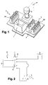
- La figure 1 est une vue partielle en perspective d'un dispositif de commutation conforme à l'invention.
- La figure 2 est un schéma électrique du circuit imprimé contenu dans un dispositif de commutation conforme à l'invention.
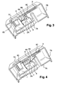
- La figure 3 est une vue en coupe selon un plan P et en perspective d'un dispositif de commutation conforme à l'invention, en position de repos.
- La figure 4 est une vue en coupe selon un plan P et en perspective d'un dispositif de commutation conforme à l'invention, en position active.
- Tel que partiellement représenté sur la figure 1, un dispositif de commutation assure la connexion d'un connecteur 1 de type RJ 45, sur une ligne de transmission de données téléphoniques à partir d'une entrée 2, qui est une connexion d'opérateur, vers une sortie 3, qui est une connexion de réseau abonné, et réalise, lors de la mise en place d'une fiche dans le connecteur 1, la déconnexion de l'entrée 2 et de la sortie 3 et la connexion de ce connecteur 1 sur l'entrée 2.
- Ce dispositif comporte un boîtier dont seule une plaque support 4 est visible sur la figure 1, portant une connexion 2A de l'entrée et une connexion 2B de la sortie pouvant être reliées électriquement par un circuit imprimé C porté par la plaque support 4 et schématisé sur la figure 2.
- Le boîtier contient également le connecteur 1 également porté par la plaque support 4 et pouvant être relié à l'entrée au moyen d'un commutateur 5 actionnable par un bouton poussoir 6, ce bouton poussoir étant lui-même actionné lors de l'enfichage d'une fiche dans le connecteur 1.
- L'ensemble du dispositif de commutation est visible sur les figures 3 et 4.
- Le boîtier comprend un socle 7A supportant la plaque support 4, et un couvercle 7B qui comporte une ouverture d'introduction 7C de la fiche en regard du connecteur 1 et qui est fermée par un clapet 8 coulissant parallèlement à la plaque support 4 le long de la paroi du couvercle 7B. Ce clapet 8 comporte une partie de butée 8A pourvue d'une rampe de glissement progressif 8B actionnant le bouton poussoir 6, lorsque le clapet 8 est coulissé pour libérer le passage au travers de l'ouverture 7C et connecter la fiche dans le connecteur 1.
- Le clapet 8 est sollicité par un ressort 9 en position fermée. Avantageusement, ce ressort 9 est un ressort hélicoïdal en butée dans une cavité agencée sur la paroi du couvercle et également en butée contre une surface du clapet 8 perpendiculaire à son sens de translation. Une tige 8C solidaire du clapet est introduite dans ce ressort 9 afin d'assurer le maintien du ressort et du clapet.
- Le clapet comporte au niveau de l'ouverture une nervure de préhension 8D permettant à l'aide d'un outil de type lame de la pousser de la position fermée représentée sur la figure 3 à la position ouverte représentée sur la figure 4. Cette poussée peut même être effectuée directement avec la fiche qui est alors simultanément introduite dans le connecteur 1 et alors retient le clapet en position ouverte, le ressort 9 étant alors comprimé.
Claims (5)
- Dispositif de commutation assurant la connexion d'un connecteur (1) sur une ligne de transmission de données téléphoniques, à partir d'une connexion d'opérateur dite entrée (2) vers une connexion de réseau abonné dite sortie (3), et réalisant, lors de la mise en place d'une fiche dans ledit connecteur, la déconnexion de l'entrée et de la sortie et la connexion de ce connecteur (1) sur ladite entrée (2), dispositif comportant un boîtier (7) présentant une connexion (2A) de ladite entrée et une connexion (3A) de ladite sortie portées par une plaque support (4) et pouvant être reliées électriquement par un circuit imprimé (C), caractérisé en ce que ledit boîtier contient également ledit connecteur (1) pouvant être relié à ladite entrée (2) au moyen d'un commutateur (5) actionnable par un bouton poussoir (6), ledit bouton poussoir (6) étant lui-même actionné lors de l'enfichage d'une fiche dans ledit connecteur (1).
- Dispositif selon la revendication 1, caractérisé en ce que ledit boîtier comporte une ouverture (7C) d'introduction de ladite fiche, fermée par un clapet (8) coulissant, ledit clapet comportant une partie de butée (8A) actionnant ledit bouton poussoir (6) lorsqu'il est coulissé pour libérer le passage au travers de ladite ouverture (7C).
- Dispositif selon la revendication 2, caractérisé en ce que ledit clapet est sollicité par un ressort (9) en position fermée.
- Dispositif selon l'une des revendications précédentes, caractérisé en ce que ledit circuit imprimé (C) est porté par ladite plaque support (4), ledit connecteur (1) étant également porté par cette plaque.
- Dispositif selon l'une des revendications précédentes, caractérisé en ce que ledit connecteur (1) est de type RJ.
Applications Claiming Priority (1)
| Application Number | Priority Date | Filing Date | Title |
|---|---|---|---|
| FR0552576A FR2890245B1 (fr) | 2005-08-26 | 2005-08-26 | Dispositif de commutation assurant la connexion d'un connecteur sur une ligne de transmission de donnees |
Publications (3)
| Publication Number | Publication Date |
|---|---|
| EP1758212A2 true EP1758212A2 (fr) | 2007-02-28 |
| EP1758212A3 EP1758212A3 (fr) | 2009-12-02 |
| EP1758212B1 EP1758212B1 (fr) | 2012-06-06 |
Family
ID=36340807
Family Applications (1)
| Application Number | Title | Priority Date | Filing Date |
|---|---|---|---|
| EP06300890A Not-in-force EP1758212B1 (fr) | 2005-08-26 | 2006-08-24 | Dispositif de commutation assurant la connexion d'un connecteur sur une ligne de transmission de données téléphoniques |
Country Status (3)
| Country | Link |
|---|---|
| EP (1) | EP1758212B1 (fr) |
| ES (1) | ES2387035T3 (fr) |
| FR (1) | FR2890245B1 (fr) |
Cited By (1)
| Publication number | Priority date | Publication date | Assignee | Title |
|---|---|---|---|---|
| EP2045886A1 (fr) | 2007-10-03 | 2009-04-08 | Legrand France | Dispositif combiné de connexion et de déconnexion électrique |
Citations (1)
| Publication number | Priority date | Publication date | Assignee | Title |
|---|---|---|---|---|
| EP0630079A1 (fr) | 1993-06-16 | 1994-12-21 | Alcatel Cable Interface | Dispositif de terminaison d'abonné |
Family Cites Families (8)
| Publication number | Priority date | Publication date | Assignee | Title |
|---|---|---|---|---|
| US4528429A (en) * | 1984-03-02 | 1985-07-09 | Dart Industries Inc. | Electrical switch-plug assembly with baffle |
| AU595890B2 (en) * | 1987-05-08 | 1990-04-12 | Adc Gmbh | Connector block with normally open or switching contacts |
| IL97227A0 (en) * | 1991-02-13 | 1992-05-25 | Bynet System Applic Ltd | Patching panel |
| GB2266015A (en) * | 1992-04-03 | 1993-10-13 | Mk Electric Ltd | Switched electrical socket outlet |
| US5483573A (en) * | 1993-06-30 | 1996-01-09 | Keptel, Inc. | Electric circuit connector with auto-termination |
| US6244907B1 (en) * | 2000-08-02 | 2001-06-12 | Avaya Technology Corp. | Selectable compatibility electrical connector assembly |
| US6494729B1 (en) * | 2001-06-04 | 2002-12-17 | Hyperchip Inc. | Insertion and extraction aid for printed circuit card |
| US6890197B2 (en) * | 2003-02-13 | 2005-05-10 | Gateway, Inc. | RJ-45 jack with RJ-11 detection |
-
2005
- 2005-08-26 FR FR0552576A patent/FR2890245B1/fr not_active Expired - Fee Related
-
2006
- 2006-08-24 EP EP06300890A patent/EP1758212B1/fr not_active Not-in-force
- 2006-08-24 ES ES06300890T patent/ES2387035T3/es active Active
Patent Citations (1)
| Publication number | Priority date | Publication date | Assignee | Title |
|---|---|---|---|---|
| EP0630079A1 (fr) | 1993-06-16 | 1994-12-21 | Alcatel Cable Interface | Dispositif de terminaison d'abonné |
Cited By (2)
| Publication number | Priority date | Publication date | Assignee | Title |
|---|---|---|---|---|
| EP2045886A1 (fr) | 2007-10-03 | 2009-04-08 | Legrand France | Dispositif combiné de connexion et de déconnexion électrique |
| FR2922056A1 (fr) * | 2007-10-03 | 2009-04-10 | Legrand France | Dispositif combine de connexion et de deconnexion electrique |
Also Published As
| Publication number | Publication date |
|---|---|
| EP1758212B1 (fr) | 2012-06-06 |
| FR2890245B1 (fr) | 2009-07-10 |
| ES2387035T3 (es) | 2012-09-12 |
| EP1758212A3 (fr) | 2009-12-02 |
| FR2890245A1 (fr) | 2007-03-02 |
Similar Documents
| Publication | Publication Date | Title |
|---|---|---|
| EP2521224B1 (fr) | Dispositif de connexion rapide pour un appareil électrique | |
| FR2824960A1 (fr) | Dispositif de raccordement a poussoir | |
| FR2806218A1 (fr) | Connecteur d'entree/sortie du type fiche | |
| FR3035744A1 (fr) | Connecteur electrique | |
| FR3013520A1 (fr) | Connecteur electrique | |
| EP3487006A1 (fr) | Système électrique comprenant un appareil électrique et un module de connexion interchangeable | |
| FR3089068A1 (fr) | Connecteur a sorties multiples | |
| EP0381101B1 (fr) | Agencement de raccordement pour câble coaxial et module de raccordement correspondant, notamment bloc de jonction | |
| EP1758212B1 (fr) | Dispositif de commutation assurant la connexion d'un connecteur sur une ligne de transmission de données téléphoniques | |
| FR3073681A1 (fr) | Dispositif de connexion et deconnexion d'un cable electrique | |
| FR2928041A1 (fr) | Prise d'alimentation electrique pour une goulotte ou analogue, utilisable individuellement ou en association. | |
| WO2010086527A1 (fr) | Appareil electrique a borne de connexion automatique | |
| FR2816452A1 (fr) | Bloc pour bornes a connexion rapide | |
| EP1916742A1 (fr) | Prise électrique | |
| EP2800206B1 (fr) | Connecteur électrique à lamelle de contact | |
| EP3790126A1 (fr) | Ensemble pour connecteurs adapté à un montage en aveugle | |
| FR2622058A1 (fr) | Connecteur electrique modulaire | |
| EP0710040B1 (fr) | Dispositif de coupure et de test pour ligne téléphonique | |
| FR2723474A1 (fr) | Connexion auto-denudante a action rapide | |
| FR2652954A2 (fr) | Systeme de prises electriques de securite. | |
| WO2017017318A1 (fr) | Prise electrique femelle securisée | |
| EP0949718B1 (fr) | Module de connexion/déconnexion de paires de conducteurs électriques isolés | |
| FR2952760A1 (fr) | Prise murale reseau a auto-test de connexion perfectionnee | |
| EP2503644A1 (fr) | Appareil électrique du type bloc de jonction | |
| FR2717584A1 (fr) | Dispositif permettant de tester un ou plusieurs câbles électriques munis de connecteurs. |
Legal Events
| Date | Code | Title | Description |
|---|---|---|---|
| PUAI | Public reference made under article 153(3) epc to a published international application that has entered the european phase |
Free format text: ORIGINAL CODE: 0009012 |
|
| AK | Designated contracting states |
Kind code of ref document: A2 Designated state(s): AT BE BG CH CY CZ DE DK EE ES FI FR GB GR HU IE IS IT LI LT LU LV MC NL PL PT RO SE SI SK TR |
|
| AX | Request for extension of the european patent |
Extension state: AL BA HR MK YU |
|
| PUAL | Search report despatched |
Free format text: ORIGINAL CODE: 0009013 |
|
| AK | Designated contracting states |
Kind code of ref document: A3 Designated state(s): AT BE BG CH CY CZ DE DK EE ES FI FR GB GR HU IE IS IT LI LT LU LV MC NL PL PT RO SE SI SK TR |
|
| AX | Request for extension of the european patent |
Extension state: AL BA HR MK RS |
|
| 17P | Request for examination filed |
Effective date: 20100602 |
|
| AKX | Designation fees paid |
Designated state(s): AT BE BG CH CY CZ DE DK EE ES FI FR GB GR HU IE IS IT LI LT LU LV MC NL PL PT RO SE SI SK TR |
|
| RAP1 | Party data changed (applicant data changed or rights of an application transferred) |
Owner name: NEXANS |
|
| GRAP | Despatch of communication of intention to grant a patent |
Free format text: ORIGINAL CODE: EPIDOSNIGR1 |
|
| RTI1 | Title (correction) |
Free format text: SWITCHING DEVICE FOR CONNECTING A CONNECTOR TO A DATA TRANSMISSION TELECOMMUNICATION LINE |
|
| RTI1 | Title (correction) |
Free format text: SWITCHING DEVICE FOR CONNECTING A CONNECTOR TO A DATA TRANSMISSION TELECOMMUNICATION LINE |
|
| GRAS | Grant fee paid |
Free format text: ORIGINAL CODE: EPIDOSNIGR3 |
|
| GRAA | (expected) grant |
Free format text: ORIGINAL CODE: 0009210 |
|
| AK | Designated contracting states |
Kind code of ref document: B1 Designated state(s): AT BE BG CH CY CZ DE DK EE ES FI FR GB GR HU IE IS IT LI LT LU LV MC NL PL PT RO SE SI SK TR |
|
| REG | Reference to a national code |
Ref country code: GB Ref legal event code: FG4D Free format text: NOT ENGLISH |
|
| REG | Reference to a national code |
Ref country code: CH Ref legal event code: EP Ref country code: AT Ref legal event code: REF Ref document number: 561417 Country of ref document: AT Kind code of ref document: T Effective date: 20120615 |
|
| REG | Reference to a national code |
Ref country code: IE Ref legal event code: FG4D Free format text: LANGUAGE OF EP DOCUMENT: FRENCH |
|
| REG | Reference to a national code |
Ref country code: DE Ref legal event code: R096 Ref document number: 602006029922 Country of ref document: DE Effective date: 20120809 |
|
| REG | Reference to a national code |
Ref country code: ES Ref legal event code: FG2A Ref document number: 2387035 Country of ref document: ES Kind code of ref document: T3 Effective date: 20120912 |
|
| REG | Reference to a national code |
Ref country code: NL Ref legal event code: VDEP Effective date: 20120606 |
|
| PG25 | Lapsed in a contracting state [announced via postgrant information from national office to epo] |
Ref country code: LT Free format text: LAPSE BECAUSE OF FAILURE TO SUBMIT A TRANSLATION OF THE DESCRIPTION OR TO PAY THE FEE WITHIN THE PRESCRIBED TIME-LIMIT Effective date: 20120606 Ref country code: FI Free format text: LAPSE BECAUSE OF FAILURE TO SUBMIT A TRANSLATION OF THE DESCRIPTION OR TO PAY THE FEE WITHIN THE PRESCRIBED TIME-LIMIT Effective date: 20120606 Ref country code: CY Free format text: LAPSE BECAUSE OF FAILURE TO SUBMIT A TRANSLATION OF THE DESCRIPTION OR TO PAY THE FEE WITHIN THE PRESCRIBED TIME-LIMIT Effective date: 20120606 Ref country code: SE Free format text: LAPSE BECAUSE OF FAILURE TO SUBMIT A TRANSLATION OF THE DESCRIPTION OR TO PAY THE FEE WITHIN THE PRESCRIBED TIME-LIMIT Effective date: 20120606 |
|
| REG | Reference to a national code |
Ref country code: AT Ref legal event code: MK05 Ref document number: 561417 Country of ref document: AT Kind code of ref document: T Effective date: 20120606 |
|
| REG | Reference to a national code |
Ref country code: LT Ref legal event code: MG4D Effective date: 20120606 |
|
| PG25 | Lapsed in a contracting state [announced via postgrant information from national office to epo] |
Ref country code: SI Free format text: LAPSE BECAUSE OF FAILURE TO SUBMIT A TRANSLATION OF THE DESCRIPTION OR TO PAY THE FEE WITHIN THE PRESCRIBED TIME-LIMIT Effective date: 20120606 Ref country code: GR Free format text: LAPSE BECAUSE OF FAILURE TO SUBMIT A TRANSLATION OF THE DESCRIPTION OR TO PAY THE FEE WITHIN THE PRESCRIBED TIME-LIMIT Effective date: 20120907 Ref country code: LV Free format text: LAPSE BECAUSE OF FAILURE TO SUBMIT A TRANSLATION OF THE DESCRIPTION OR TO PAY THE FEE WITHIN THE PRESCRIBED TIME-LIMIT Effective date: 20120606 |
|
| PG25 | Lapsed in a contracting state [announced via postgrant information from national office to epo] |
Ref country code: EE Free format text: LAPSE BECAUSE OF FAILURE TO SUBMIT A TRANSLATION OF THE DESCRIPTION OR TO PAY THE FEE WITHIN THE PRESCRIBED TIME-LIMIT Effective date: 20120606 Ref country code: AT Free format text: LAPSE BECAUSE OF FAILURE TO SUBMIT A TRANSLATION OF THE DESCRIPTION OR TO PAY THE FEE WITHIN THE PRESCRIBED TIME-LIMIT Effective date: 20120606 Ref country code: CZ Free format text: LAPSE BECAUSE OF FAILURE TO SUBMIT A TRANSLATION OF THE DESCRIPTION OR TO PAY THE FEE WITHIN THE PRESCRIBED TIME-LIMIT Effective date: 20120606 Ref country code: NL Free format text: LAPSE BECAUSE OF FAILURE TO SUBMIT A TRANSLATION OF THE DESCRIPTION OR TO PAY THE FEE WITHIN THE PRESCRIBED TIME-LIMIT Effective date: 20120606 Ref country code: RO Free format text: LAPSE BECAUSE OF FAILURE TO SUBMIT A TRANSLATION OF THE DESCRIPTION OR TO PAY THE FEE WITHIN THE PRESCRIBED TIME-LIMIT Effective date: 20120606 Ref country code: SK Free format text: LAPSE BECAUSE OF FAILURE TO SUBMIT A TRANSLATION OF THE DESCRIPTION OR TO PAY THE FEE WITHIN THE PRESCRIBED TIME-LIMIT Effective date: 20120606 Ref country code: IS Free format text: LAPSE BECAUSE OF FAILURE TO SUBMIT A TRANSLATION OF THE DESCRIPTION OR TO PAY THE FEE WITHIN THE PRESCRIBED TIME-LIMIT Effective date: 20121006 |
|
| PG25 | Lapsed in a contracting state [announced via postgrant information from national office to epo] |
Ref country code: PT Free format text: LAPSE BECAUSE OF FAILURE TO SUBMIT A TRANSLATION OF THE DESCRIPTION OR TO PAY THE FEE WITHIN THE PRESCRIBED TIME-LIMIT Effective date: 20121008 Ref country code: PL Free format text: LAPSE BECAUSE OF FAILURE TO SUBMIT A TRANSLATION OF THE DESCRIPTION OR TO PAY THE FEE WITHIN THE PRESCRIBED TIME-LIMIT Effective date: 20120606 |
|
| REG | Reference to a national code |
Ref country code: CH Ref legal event code: PL |
|
| PG25 | Lapsed in a contracting state [announced via postgrant information from national office to epo] |
Ref country code: MC Free format text: LAPSE BECAUSE OF NON-PAYMENT OF DUE FEES Effective date: 20120831 |
|
| PLBE | No opposition filed within time limit |
Free format text: ORIGINAL CODE: 0009261 |
|
| STAA | Information on the status of an ep patent application or granted ep patent |
Free format text: STATUS: NO OPPOSITION FILED WITHIN TIME LIMIT |
|
| PG25 | Lapsed in a contracting state [announced via postgrant information from national office to epo] |
Ref country code: DK Free format text: LAPSE BECAUSE OF FAILURE TO SUBMIT A TRANSLATION OF THE DESCRIPTION OR TO PAY THE FEE WITHIN THE PRESCRIBED TIME-LIMIT Effective date: 20120606 Ref country code: LI Free format text: LAPSE BECAUSE OF NON-PAYMENT OF DUE FEES Effective date: 20120831 Ref country code: CH Free format text: LAPSE BECAUSE OF NON-PAYMENT OF DUE FEES Effective date: 20120831 |
|
| 26N | No opposition filed |
Effective date: 20130307 |
|
| REG | Reference to a national code |
Ref country code: IE Ref legal event code: MM4A |
|
| GBPC | Gb: european patent ceased through non-payment of renewal fee |
Effective date: 20120906 |
|
| PG25 | Lapsed in a contracting state [announced via postgrant information from national office to epo] |
Ref country code: BG Free format text: LAPSE BECAUSE OF FAILURE TO SUBMIT A TRANSLATION OF THE DESCRIPTION OR TO PAY THE FEE WITHIN THE PRESCRIBED TIME-LIMIT Effective date: 20120906 Ref country code: IE Free format text: LAPSE BECAUSE OF NON-PAYMENT OF DUE FEES Effective date: 20120824 Ref country code: GB Free format text: LAPSE BECAUSE OF NON-PAYMENT OF DUE FEES Effective date: 20120906 Ref country code: DE Free format text: LAPSE BECAUSE OF NON-PAYMENT OF DUE FEES Effective date: 20130301 |
|
| REG | Reference to a national code |
Ref country code: DE Ref legal event code: R119 Ref document number: 602006029922 Country of ref document: DE Effective date: 20130301 |
|
| PG25 | Lapsed in a contracting state [announced via postgrant information from national office to epo] |
Ref country code: TR Free format text: LAPSE BECAUSE OF FAILURE TO SUBMIT A TRANSLATION OF THE DESCRIPTION OR TO PAY THE FEE WITHIN THE PRESCRIBED TIME-LIMIT Effective date: 20120606 |
|
| PG25 | Lapsed in a contracting state [announced via postgrant information from national office to epo] |
Ref country code: LU Free format text: LAPSE BECAUSE OF NON-PAYMENT OF DUE FEES Effective date: 20120824 |
|
| PG25 | Lapsed in a contracting state [announced via postgrant information from national office to epo] |
Ref country code: HU Free format text: LAPSE BECAUSE OF FAILURE TO SUBMIT A TRANSLATION OF THE DESCRIPTION OR TO PAY THE FEE WITHIN THE PRESCRIBED TIME-LIMIT Effective date: 20060824 |
|
| PGFP | Annual fee paid to national office [announced via postgrant information from national office to epo] |
Ref country code: ES Payment date: 20140826 Year of fee payment: 9 |
|
| PGFP | Annual fee paid to national office [announced via postgrant information from national office to epo] |
Ref country code: IT Payment date: 20140826 Year of fee payment: 9 |
|
| PGFP | Annual fee paid to national office [announced via postgrant information from national office to epo] |
Ref country code: BE Payment date: 20140820 Year of fee payment: 9 |
|
| PG25 | Lapsed in a contracting state [announced via postgrant information from national office to epo] |
Ref country code: IT Free format text: LAPSE BECAUSE OF NON-PAYMENT OF DUE FEES Effective date: 20150824 |
|
| REG | Reference to a national code |
Ref country code: FR Ref legal event code: PLFP Year of fee payment: 11 |
|
| PG25 | Lapsed in a contracting state [announced via postgrant information from national office to epo] |
Ref country code: ES Free format text: LAPSE BECAUSE OF NON-PAYMENT OF DUE FEES Effective date: 20150825 |
|
| PG25 | Lapsed in a contracting state [announced via postgrant information from national office to epo] |
Ref country code: BE Free format text: LAPSE BECAUSE OF NON-PAYMENT OF DUE FEES Effective date: 20150831 |
|
| REG | Reference to a national code |
Ref country code: FR Ref legal event code: PLFP Year of fee payment: 12 |
|
| REG | Reference to a national code |
Ref country code: ES Ref legal event code: FD2A Effective date: 20180709 |
|
| REG | Reference to a national code |
Ref country code: ES Ref legal event code: FD2A Effective date: 20180710 |
|
| REG | Reference to a national code |
Ref country code: FR Ref legal event code: PLFP Year of fee payment: 13 |
|
| PGFP | Annual fee paid to national office [announced via postgrant information from national office to epo] |
Ref country code: FR Payment date: 20190822 Year of fee payment: 14 |
|
| PG25 | Lapsed in a contracting state [announced via postgrant information from national office to epo] |
Ref country code: FR Free format text: LAPSE BECAUSE OF NON-PAYMENT OF DUE FEES Effective date: 20200831 |