EP1757808A1 - Link mechanism and variable displacement compressor - Google Patents
Link mechanism and variable displacement compressor Download PDFInfo
- Publication number
- EP1757808A1 EP1757808A1 EP05727447A EP05727447A EP1757808A1 EP 1757808 A1 EP1757808 A1 EP 1757808A1 EP 05727447 A EP05727447 A EP 05727447A EP 05727447 A EP05727447 A EP 05727447A EP 1757808 A1 EP1757808 A1 EP 1757808A1
- Authority
- EP
- European Patent Office
- Prior art keywords
- linkage
- arms
- arm
- linking pin
- tilting
- Prior art date
- Legal status (The legal status is an assumption and is not a legal conclusion. Google has not performed a legal analysis and makes no representation as to the accuracy of the status listed.)
- Withdrawn
Links
Images











Classifications
-
- F—MECHANICAL ENGINEERING; LIGHTING; HEATING; WEAPONS; BLASTING
- F04—POSITIVE - DISPLACEMENT MACHINES FOR LIQUIDS; PUMPS FOR LIQUIDS OR ELASTIC FLUIDS
- F04B—POSITIVE-DISPLACEMENT MACHINES FOR LIQUIDS; PUMPS
- F04B27/00—Multi-cylinder pumps specially adapted for elastic fluids and characterised by number or arrangement of cylinders
- F04B27/08—Multi-cylinder pumps specially adapted for elastic fluids and characterised by number or arrangement of cylinders having cylinders coaxial with, or parallel or inclined to, main shaft axis
- F04B27/10—Multi-cylinder pumps specially adapted for elastic fluids and characterised by number or arrangement of cylinders having cylinders coaxial with, or parallel or inclined to, main shaft axis having stationary cylinders
- F04B27/1036—Component parts, details, e.g. sealings, lubrication
- F04B27/1081—Casings, housings
-
- F—MECHANICAL ENGINEERING; LIGHTING; HEATING; WEAPONS; BLASTING
- F04—POSITIVE - DISPLACEMENT MACHINES FOR LIQUIDS; PUMPS FOR LIQUIDS OR ELASTIC FLUIDS
- F04B—POSITIVE-DISPLACEMENT MACHINES FOR LIQUIDS; PUMPS
- F04B27/00—Multi-cylinder pumps specially adapted for elastic fluids and characterised by number or arrangement of cylinders
- F04B27/08—Multi-cylinder pumps specially adapted for elastic fluids and characterised by number or arrangement of cylinders having cylinders coaxial with, or parallel or inclined to, main shaft axis
- F04B27/0873—Component parts, e.g. sealings; Manufacturing or assembly thereof
- F04B27/0878—Pistons
- F04B27/0886—Piston shoes
-
- F—MECHANICAL ENGINEERING; LIGHTING; HEATING; WEAPONS; BLASTING
- F04—POSITIVE - DISPLACEMENT MACHINES FOR LIQUIDS; PUMPS FOR LIQUIDS OR ELASTIC FLUIDS
- F04B—POSITIVE-DISPLACEMENT MACHINES FOR LIQUIDS; PUMPS
- F04B27/00—Multi-cylinder pumps specially adapted for elastic fluids and characterised by number or arrangement of cylinders
- F04B27/08—Multi-cylinder pumps specially adapted for elastic fluids and characterised by number or arrangement of cylinders having cylinders coaxial with, or parallel or inclined to, main shaft axis
- F04B27/0873—Component parts, e.g. sealings; Manufacturing or assembly thereof
- F04B27/0895—Component parts, e.g. sealings; Manufacturing or assembly thereof driving means
-
- F—MECHANICAL ENGINEERING; LIGHTING; HEATING; WEAPONS; BLASTING
- F04—POSITIVE - DISPLACEMENT MACHINES FOR LIQUIDS; PUMPS FOR LIQUIDS OR ELASTIC FLUIDS
- F04B—POSITIVE-DISPLACEMENT MACHINES FOR LIQUIDS; PUMPS
- F04B39/00—Component parts, details, or accessories, of pumps or pumping systems specially adapted for elastic fluids, not otherwise provided for in, or of interest apart from, groups F04B25/00 - F04B37/00
- F04B39/12—Casings; Cylinders; Cylinder heads; Fluid connections
- F04B39/125—Cylinder heads
-
- Y—GENERAL TAGGING OF NEW TECHNOLOGICAL DEVELOPMENTS; GENERAL TAGGING OF CROSS-SECTIONAL TECHNOLOGIES SPANNING OVER SEVERAL SECTIONS OF THE IPC; TECHNICAL SUBJECTS COVERED BY FORMER USPC CROSS-REFERENCE ART COLLECTIONS [XRACs] AND DIGESTS
- Y10—TECHNICAL SUBJECTS COVERED BY FORMER USPC
- Y10T—TECHNICAL SUBJECTS COVERED BY FORMER US CLASSIFICATION
- Y10T74/00—Machine element or mechanism
- Y10T74/18—Mechanical movements
- Y10T74/18888—Reciprocating to or from oscillating
- Y10T74/1892—Lever and slide
- Y10T74/18936—Slidable connections
Definitions
- the present invention relates to a linkage mechanism capable of relative rotating as transferring rotary torque and a variable displacement compressor using the linkage mechanism.
- a variable displacement compressor includes a drive shaft, a rotor which is fixed to the drive shaft and rotates integrally with the drive shaft, and a swash plate which is attached to the drive shaft via a slidable hinge ball and is tiltable with respect to the drive shaft. Piston stroke is changed by changing the inclination angle of the swash plate so as to change the discharging amount.
- a linkage mechanism is provided between the rotor and the swash plate (see, for example, Japanese Patent Application Laid-Open Publications No. 2003-172417 and No. 10-176658 ).
- a linkage mechanism described in the Publication No. 2003-172417 includes a pair of rotor arms which extend from a rotor toward a swash plate and face to each other, a single swash plate arm which extends from the swash plate toward the rotor, and a link whose first end is linked to the rotor arms by a first linking pin and second end is linked to the swash plate arm by a second linking pin.
- the first end of the link is inserted between the pair of rotor arms of the rotor and linked to the rotor arms by the first linking pin.
- the second end of the link includes a pair of link arms facing each other, the swash plate arm is inserted between the link arms.
- the second end of the link is linked to the swash plate arm by a second linking pin.
- the swash plate arm is sandwiched by the pair of link arms provide at the second end of the link and the first end of the link is sandwiched by the pair of rotor arms.
- An object of the present invention is to provide a linkage mechanism with improved durability and a variable displacement compressor using the linkage mechanism.
- the first aspect of the present invention is a linkage mechanism including: a rotating member fixed to a drive shaft and rotating integrally with the drive shaft; a tilting member slidably attached to the drive shaft and being tiltable with respect to the drive shaft; a pair of arms extending from the rotating member toward the tilting member and facing each other in a rotary torque transfer direction; a pair of arms extending form the tilting member toward the rotating member and facing each other in the rotary torque transfer direction; and a linkage member inserted between the pair of arms of the rotating member that face each other and between the pair of arms of the tilting member that face each other.
- the first aspect of the present invention includes three arms (in the side of the rotating member, there are three arms including the pair of arms of the rotating member and the linkage member inserted therebetween) (in the side of the tilting member, there are three arms including the pair arms of the tilting member and the linkage member inserted therebetween). Accordingly, the torque durability of the linkage mechanism can be improved since each member is made thicker in the torque transfer direction without increasing the size of the linkage mechanism as a whole, comparing to conventional structures (see, for example, Japanese Patent Application Laid-Open Publications No. 2003-172417 and No. 10-176658 ).
- the linkage mechanism can be significantly downsized as maintaining sufficient thickness of each member in torque transfer direction, comparing to conventional techniques.
- one end of the linkage member may be rotatably linked to the pair of arms of the rotating member by the first linking pin and the other end of the linkage member may be rotatably linked to the pair of arms of the tilting member by the second linking pin.
- a distance between the pair of arms of the rotating member and a distance between the pair of arms of the tilting member may be formed in the same size.
- the linkage member can be formed in a simple rectangular shape so that one end is inserted between the pair of arms of the rotating member and the other end is inserted between the pair of arms of tilting member.
- the manufacturing cost of the linkage member can be significantly reduced.
- the linkage member is made of aluminum, it can be made by extruding.
- the first linking pin and the second linking pin may have the same diameter and length.
- a pin can be used as the first linking pin and the second linking pin.
- the manufacturing cost of the linkage mechanism can be reduced.
- a manufacturing die can be used for both of the first linking pin and the second linking pin, the number of necessary dies can be reduced.
- load of workers can be reduced since they do not need to distinguish the storing locations of the first linking pin and the second linking pin in an assembling process of the linkage mechanism.
- the second aspect of the present invention is a linkage mechanism including: a rotating member fixed to a drive shaft and rotating integrally with the drive shaft; a tilting member slidably attached to the drive shaft and being tiltable with respect to the drive shaft; an arm extending from the rotating member toward the tilting member; an arm extending form the tilting member toward the rotating member; and a linkage member provided between the arm of the rotating member and the arm of the tilting member.
- a slit is provided to one of the arm of the rotating member and one end of the linkage member, the other of the arm of the rotating member and the one end of the linkage member is inserted into the slit, the arm of the rotating member and the one end of the linkage member are rotatably connected each other by a first linking pin in a condition that the other is inserted into the one.
- a maximum inclination angle of the linkage member relative to the arm of the rotating member corresponds to a maximum inclination angle of the first linking pin in a bearing clearance between the first linking pin and a bearing hole for the first linking pin.
- the portion inserted in the slit contacts with only one of the opposite surfaces of the slit. Accordingly, unlike conventional structures, the portion inserted in the slit does not lockingly dig into the opposite surfaces of the slit at two points.
- the first linking pin may be fixed to a fixing hole provided to one of the arms of the rotating member and the linkage member and rotatably supported by the bearing hole provided to the other of the arms of the rotating member and the linkage member.
- the design of the linkage mechanism becomes easy comparing to such a structure in which the first linking pin is rotatably supported by bearing holes provided to the arms of the rotating member and the linkage member respectively.
- the third aspect of the present invention is a linkage mechanism including a rotating member fixed to a drive shaft and rotating integrally with the drive shaft; a tilting member slidably attached to the drive shaft and being tiltable with respect to the drive shaft; an arm extending from the rotating member toward the tilting member; an arm extending form the tilting member toward the rotating member; and a linkage member provided between the arm of the rotating member and the arm of the tilting member.
- a slit is provided to one of the arm of the tilting member and the other end of the linkage member, the other of the arm of the tilting member and the other end of the linkage member inserted into the slit, the arm of the tilting member and the other end of the linkage member are rotatably connected each other by a second linking pin.
- a maximum inclination angle of the linkage member relative to the arm of the tilting member corresponds to a maximum inclination angle of the second linking pin in a bearing clearance between the second linking pin and a bearing hole for the second linking pin.
- the portion inserted in the slit contacts with only one of the opposite surfaces of the slit. Accordingly, unlike conventional structures, the portion inserted in the slit does not lockingly dig into the opposite surfaces of the slit at two points.
- the second linking pin may be fixed to a fixing hole provided one of the arms of the tilting member and the linkage member and supported by the bearing hole provided to the other of the arms of the tilting member and the linkage member.
- the design of the linkage mechanism becomes easy comparing to such a structure in which the second linking pin is rotatably supported by bearing holes provided to the arms of the tilting member and the linkage member respectively.
- the linking pin may include a reduced-diameter portion, at axial ends, where the diameter is reduced at a certain curvature, at a curvature that gradually increases, or a curvature that increases in stages.
- the bearing hole may include an expanded-diameter portion, at axial ends, where the diameter is enlarged at a certain curvature, at a curvature that gradually increases, or at a curvature that increases in stages.
- the slit may be provided to the arm of the rotating member and an end of the linkage member is inserted into the slit, and the slit may be provided to the arm of the tilting member and the other end of the linkage member inserted into the slit.
- the aspects of the present invention may have a pair of arms that extend from the rotating member toward the tilting member and face each other across the slit, a pair of arms that extend from the tilting member toward the rotating member and face each other across the slit, and a linkage member that is inserted between the pair of arms of the rotating member and between the pair of arms of the tilting member.
- the present invention includes three arms (in the side of the rotating member, there are three arms including the arms of the rotating member and the linkage member inserted therebetween) (in the side of the tilting member, there are three arms including the arms of the tilting member and the linkage member inserted therebetween). Accordingly, the torque durability of the linkage mechanism can be improved since the each member is made thicker in the torque transfer direction without increasing the size of the linkage mechanism as a whole, comparing to conventional structures. If it is required to reduce the size of the linkage mechanism in the torque transfer direction according to layout restrictions due to a request for downsizing devices, the linkage mechanism can be significantly downsized as maintaining sufficient thickness of each member in torque transfer direction, comparing to conventional techniques.
- a width of the slit (between the pair of arms) of the rotating member and a width of the slit (between the pair of arms) of the tilting member may be formed in same width.
- the linkage member whose one end is inserted into the slit of the rotating member and whose other end is inserted into the slit of the tilting member can be formed in a simple rectangular shape.
- the manufacturing cost of the linkage member can be significantly reduced.
- the linkage member is made of aluminum, it can be made by extruding.
- first linking pin and the second linking pin may have the same diameter and length.
- the first linking pin and the second linking pin have the same diameter and length, a pin can be used as the first linking pin and the second linking pin. Accordingly, the manufacturing cost of the linkage mechanism can be reduced. For example, since a die can be used for both of the first linking pin and the second linking pin, the number of necessary dies can be reduced. Further, there is an advantage such that load of workers can be reduced since they do not need to distinguish the storing locations of the first linking pin and the second linking pin in an assembling process of the linkage mechanism.
- variable displacement compressor and a linkage mechanism used in the variable displacement compressor of embodiments of the present invention will be described with reference to the accompanying drawings.
- a compressor 1 of the first embodiment is a swash plate type variable displacement compressor.
- the variable displacement compressor 1 includes a cylinder block 2 having a plurality of cylinder bores 3 placed evenly spaced apart in a circumferential direction, a front housing 4 attached to a front end of the cylinder block 2 and defining a crank chamber 5 with the cylinder block 2, and a rear housing 6 attached to a rear end of the cylinder block 2 via a valve plate 9 and having a suction chamber 7 and a discharge chamber 8 therein.
- the cylinder block 2, the front housing 4, and the rear housing 6 are fixedly connected to one another by a plurality of bolts B.
- the valve plate 9 is formed with a suction port (not shown) that communicates with the cylinder bore 3 and the suction chamber 7, and a discharge port 12 that communicates with the cylinder bore 3 and the discharge chamber 8.
- a valve system (not shown) adapted to open or close the suction port 11 is provided on the valve plate 9 at the cylinder block side.
- a valve system (not shown) adapted to open or close the discharge port 12 is provided on the valve plate 9 at the rear housing side.
- a gasket is interposed between the valve plate 9 and the rear housing 6 for providing an airtight seal between the suction chamber 7 and the discharge chamber 8.
- a drive shaft S is supported by bearings 17, 18 in support holes 19, 20 formed at the center portions of the cylinder block 2 and the front housing 4so that the drive shaft S is rotatable in the crank chamber 5.
- the crank chamber 5 accommodates, a rotor 21 as a “rotating member” fixed to the drive shaft S, a hinge ball 22 slidably attached to the drive shaft S, and a swash plate 24 as a “tilting member” tiltably attached to the hinge ball 22.
- the swash plate 24 includes a hub 25 tiltably and rotatably attached to the hinge ball 22 and a swash plate body 26 fixed to a boss segment 25a of the hub 25.
- a piston 29 is slidably contained in each cylinder bore 3, and engaged with the swash plate body 26 of the swash plate 24 via a pair of hemispherical-shaped shoes 30, 30.
- a linkage mechanism 40 is provided between the rotor 21 as a rotating member and the hub 25 of the swash plate 24 as a tilting member.
- the linkage mechanism 40 transfers rotary torque from the rotor 21 to the swash plate 24 as allowing the inclination angle of the swash plate 24 to change.
- the linkage mechanism 40 will hereinafter be described in detail.
- the inclination angle of the swash plate 24 reduces when the hinge ball 22 moves toward the cylinder block 2. On the other hand, the inclination angle of the swash plate 24 increases when the hinge ball 22 moves away from the cylinder block 2.
- variable displacement compressor includes a pressure control mechanism having a gas extraction passage (not shown) that allows the crank chamber 5 to communicate with the suction chamber 7, an gas supply passage (not shown) that allows the crank chamber 5 to communicate with the discharge chamber 8, and a control valve 33 that is provided in the midstream of the gas supply passage to open and close the gas supply passage.
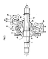
- Fig. 2 shows the inclination angle of the swash plate 24 in a full stroke mode
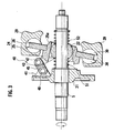
- Fig. 3 shows the inclination angle of the swash plate 24 in a middle stroke mode
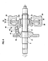
- Fig. 4 shows the inclination angle of the swash plate 24 in a destroke mode.
- Fig. 5 is a perspective view showing a linkage mechanism 40
- Fig. 6 is a side view showing the linkage mechanism 40 with a cross-section taken along line VI-VI in Fig. 2
- Fig. 7 is an enlarged sectional view showing the linkage mechanism 40
- Fig. 8 is a side view showing the rotor 21
- Fig. 9 is a vertical sectional view showing the rotor 21
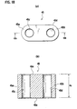
- Figs. 10(a) and 10(b) are views showing the linkage member
- Fig. 11 is a side view showing the hub 25 of the swash plate 24
- Fig. 12 is a vertical sectional view showing the hub 25 of the swash plate 24.
- the linkage mechanism 40 includes a pair of arms 41, 41 that extend from the rotor 21 toward the hub 25 and face each other in the rotary torque transfer direction, a pair of arms 43, 43 that extend from the hub 25 toward the rotor 21 and face each other in the rotary torque transfer direction, and a linkage member 45 that is inserted between the pair of opposite arms 41, 41 of the rotor 21 and between the pair of opposite arms 43, 43 of the hub 25.
- the structure of the present embodiment includes a pair of arms 41, 41 that extend from a rotor 21 as a "rotating member” toward a hub 25 of a swash plate 24 as a “tilting member” and face each other in the rotary torque transfer direction, a pair of arms 43, 43 that extend from the hub 25 toward the rotor 21 and face each other in the rotary torque transfer direction, and a linkage member 45 that is inserted between the pair of facing arms 41, 41 of the rotor 21 and between the pair of facing arms 43, 43 of the hub 25.
- conventional structures see, for example, Japanese Patent Application Laid-Open Publications No. 2003-172417 and No.
- the present embodiment includes three arms (in the side of the rotor 21, there are three arms including the pair of arms 41, 41 of the rotor 21 and the linkage member 45 inserted therebetween) (in the side of hub 25, there are three arms including the pair of arms 43, 43 of the hub 25 and the linkage member 45 inserted therebetween).
- the linkage member 45 whose first end 45a is inserted between the pair of arms 41, 41 of the rotor 21 and second end 45b is inserted between the pair of arms 43, 43 of the hub 25 can be formed in a simple rectangular shape. As a result, complicated cutting works are not required when manufacturing the linkage member 45. The manufacturing cost of the linkage member 45 can be significantly reduced. For example, when the linkage member is made of aluminum, it can be made by extruding.
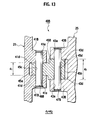
- the width d2 between a pair of arms 43B, 43B of a hub 25 is formed larger than the width d1 between a pair of arms 41B, 41B of a rotor 21.
- the width ( ⁇ d1) of a portion 45a which is to be inserted between the arms 41B, 41B of the rotor 21 is smaller than the width ( ⁇ d2) of a portion 45b which is to be inserted between the arms 43B, 43B of the hub 25.
- the linkage member 45B is formed with steps.
- the length of the second linking pin 47B is made longer than the length of the first linking pin 46B.
- the linkage mechanism 40B shown in Fig. 13 includes a pair of arms 41B, 41B that extend from a rotor 21 as a "rotating member” toward a hub 25 of a swash plate 24 as a “tilting member” and face each other in the rotary torque transfer direction, a pair of arms 43B, 43B that extend from the hub 25 toward the rotor 21 and face each other in the rotary torque transfer direction, and a linkage member 45B that is inserted between the facing arms 41B, 41B of the rotor 21 and between the facing arms 43B, 43B of the hub 25.
- Unlike the conventional techniques see, for example, Japanese Patent Application Laid-Open Publications No. 2003-172417 and No.
- the linkage mechanism 40B includes three arms (in the side of the rotor 21, there are three arms including the arms 41B, 41B of the rotor 21 and the linkage member 45B inserted therebetween) (in the side of hub 25, there are three arms including the arms 43B, 43B of the hub 25 and the linkage member 45B inserted therebetween).
- each of the members (41B, 43B, 45B) can be made thicker in the torque transfer direction than the conventional structures so that the torque durability of the linkage mechanism 40B can be improved without increasing the size of the linkage mechanism 40B.
- the linkage mechanism 40B can be significantly downsized as maintaining sufficient thickness of each member (41B, 43B, 45B) in torque transfer direction, comparing to conventional structures.
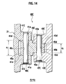
- the width d2 between a pair of arms 43C, 43C of a hub 25 is made smaller than the width d1 between a pair of arms 41C, 41C of a rotor 21.
- the width ( ⁇ d1) of a portion 45a which is to be inserted between the arms 41C, 41C of the rotor 21 is made larger than the width ( ⁇ d2) of a portion 45b which is to be inserted between the arms 43C, 43C of the hub 25.
- the linkage member 45C is formed with steps.
- the second linking pin 47B is made shorter in length than the first linking pin 46B.
- the linkage mechanism 40C shown in Fig. 14 also includes a pair of arms 41C, 41C that extend from a rotor 21 as a "rotating member” toward a hub 25 of a swash plate 24 as a “tilting member” and face each other in the rotary torque transfer direction, a pair of arms 43C, 43C that extend from the hub 25 toward the rotor 21 and face each other in the rotary torque transfer direction, and a linkage member 45C that is inserted between the facing arms 41C, 41C of the rotor 21 and between the facing arms 43C, 43C of the hub 25.
- Unlike the conventional structures see, for example, Japanese Patent Application Laid-Open Publications No.
- the linkage mechanism 40C includes three arms (in the side of the rotor 21, there are three arms including the arms 41C, 41C of the rotor 21 and the linkage member 45C inserted therebetween) (in the side of hub 25, there are three arms including the arms 43C, 43C of the hub 25 and the linkage member 45C inserted therebetween).
- each of the members (41C, 43C, 45C) is made thicker in the torque transfer direction than the conventional structures so that the torque durability of the linkage mechanism 40C is improved.
- the linkage mechanism 40C can be significantly downsized as maintaining sufficient thickness of each member (41C, 43C, 45C) in torque transfer direction, comparing to conventional structures.
- a linkage mechanism includes a pair of arms that extend from a rotating member toward a tilting member and face each other in the rotary torque transfer direction, a pair of arms that extend from the tilting member toward the rotating member and face each other in the rotary torque transfer direction, and a linkage member that is inserted between the facing arms of the rotating member and between the facing arms of the tilting member.
- the first embodiment includes three arms (in the side of the rotating member, there are three arms including the arms of the rotating member and the linkage member inserted therebetween) (in the side of the tilting member, there are three arms including the arms of the tilting member and the linkage member inserted therebetween).
- the torque durability of the linkage mechanism can be improved because each member can be made thicker in the torque transfer direction without increasing the size of the linkage mechanism as a whole, than the conventional structures (see, for example, Japanese Patent Application Laid-Open Publications No. 2003-172417 and No. 10-176658 ).
- the linkage mechanism 40F includes a pair of arms 41, 41 that extend from a rotor 21 toward a swash plate 24 and face each other in the rotary torque transfer direction across a slit 41s, a pair of arms 43, 43 that extend from the swash plate 24 toward the rotor 21 and face each other in the rotary torque transfer direction across a slit 43s, and a linkage member 45 that is inserted into the slit 41s of the rotor 21 (that is, between the arms 41, 41) and into the slit 43s of the swash plate 24 (that is, between the arms 43, 43).
- the width d1 of the slit 41s of the rotor 21 (that is, the width between inner surfaces 41d, 41d of the arms 41, 41 of the rotor 21) and the width d2 of the slit 43s of the swash plate 24 (that is, the width between inner surfaces 43d, 43d of the arms 43, 43 of the swash plate 24) are formed in the same width.
- the linkage member 45 is formed in a rectangular shape and its outer surfaces 45e, 45e are formed flat without any unevenness.
- the width d0 of the linkage member 45 (that is, the width between the outer surfaces 45e, 45e of the linkage member 45) is set smaller than the width d1 of the slit 41s of the rotor 21 and the width d2 of the slit 43 of the swash plate 24.
- the second embodiment brings about the following effects.
- a slit 43s for receiving one of arms 43 of a tilting member 25 and a second end 45b of the linkage member 45 is provided to the other of the arms 43 of the tilting member 25 and the second end 45b of the linkage member 45 (the second end 45b of the linkage member 45, in this embodiment) and they are pivotably connected each other by a second linking pin 47 in a state that the other 45 of them is inserted into the one 43 of them.
- the linkage member 45 does not lockingly dig into at two points.
- the first linking pin 46 is fixed to a fixing hole 45c formed in one of the arms 41 of the rotating member and the linkage member 45 (linkage member 45, in this embodiment) and supported by a bearing holes 41a, 41a formed in the other of the arms 41 of the rotating member and the linkage member 45 (the arms 41 of the rotating member, in this embodiment).
- a fixing hole 45c formed in one of the arms 41 of the rotating member and the linkage member 45 (linkage member 45, in this embodiment) and supported by a bearing holes 41a, 41a formed in the other of the arms 41 of the rotating member and the linkage member 45 (the arms 41 of the rotating member, in this embodiment).
- the second linking pin 47 is fixed to a fixing hole 45d formed in one of the arms 43 of the tilting member and the linkage member 45 (linkage member 45, in this embodiment) and rotatably supported by bearing holes 43a, 43a formed in the other of the arms 43 of the tilting member and the linkage member 45 (the arms 43 of the tilting member, in this embodiment).
- bearing holes are provided to the arms of the tilting member and the linkage member, one of the holes is made as a fixing hole 45d so that the design of the linkage mechanism becomes easier.
- the first end 45a of the linkage member 45 is inserted into the slit 41s which is provided to the arms 41 of the rotating member, and the second end 45b of the linkage member 45 is inserted into the slit 43s which is provided to the arms 43 of the tilting member.
- the second embodiment has the pair of arms 43, 43 that extend from the rotating member 21 toward the tilting member 25 and face each other across the slit 41s, the pair of arms 43, 43 that extend from the tilting member 25 toward the rotating member 21 and face each other across the slit 43s, and a linkage member 45 that is inserted between the arms 41, 41 of the rotating member and between the arms 43, 43 of the tilting member.
- the present embodiment includes three arms (in the side of the rotating member, there are three arms including the arms 41, 41 of the rotating member and the linkage member 45 inserted therebetween) (in the side of the tilting member, there are three arms including the arms 43, 43 of the tilting member and the linkage member 45 inserted therebetween).
- the linkage mechanism 40F can be significantly downsized as maintaining sufficient thickness of each member (41, 43, 45) in torque transfer direction, comparing to conventional structures.
- the width d1 of the slit 41s of the arms 41, 41 of the rotating member and the width d2 of the slit 43s of the arms 43, 43 of the tilting member are formed in same width. Accordingly, the width d1 of the slit 41s of the arms 41, 41 of the rotating member and the width d2 of the slit 43s of the arms 43, 43 of the tilting member are formed in same width. Accordingly, the linkage member 45 can be made in a simple rectangular shape. As a result, complicated cutting works are not required when manufacturing the linkage member 45, so that the manufacturing cost of the linkage member 45 can be significantly reduced. For example, when the linkage member is made of aluminum, it can be made by extruding and the like.
- Figs. 17 to 19 are views showing the first modification of the linkage mechanism according to the second embodiment.
- a linkage mechanism 40G of the first modification includes reduced-diameter portions 60, at axial ends thereof, where the diameter is reduced at a certain curvature, at a curvature that gradually increases, or at a curvature that increases in stages.
- the linking pins 46, 47 are crowned.
- reference “61" in Fig. 19 represents a linear portion located closer to the end than the curved reduced-diameter portion 60.
- the curvature radius is set according to the quality of material of the linking pins and arms or the pressure between the surfaces of the linking pins and the bearing holes. In this case, however, it is preferable that the curvature radius is larger than the axial length of the linking pins 46, 47.
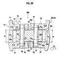
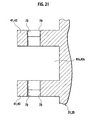
- Figs. 20 and 21 are views showing the second modification of the linkage mechanism according to the second embodiment.
- a linkage mechanism 40H of the second modification includes expanded-diameter portions 70, at the axial ends of the bearing holes 41a, 41a, and 43a, 43a.
- the diameters of the expanded-diameter portions 70 are expanded at certain curvature, at a curvature that gradually increases, or at a curvature that increases in stages. Accordingly, a similar effect to the crowned linking pins 46, 47 can be obtained.
- the second modification when the linking pins 46, 47 tilt maximally within the bearing clearance of the bearing holes 41a, 41a, the contact area of the linking pins 46, 47 and the bearing holes 41a, 41a is increased at the edges so that they do no dig into each other.
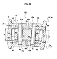
- holes 41a, 41a provided to arms 41, 41 of a rotating member are fixing holes to which a first linking pin 46 is inserted with force to be fixed thereto, and a hole 45c provided to a linkage member 45 is a bearing hole to which the first linking pin 46 is rotatably supported, in contrast to the second embodiment.
- holes 43a, 43a provided to arms 43, 43 of a tilting member is fixing holes to which a second linking pin 47 is inserted with force to be fixed thereto, and another hole 45c provided the linkage member 45 is a bearing hole to which the second linking pin 47 is rotatably supported, in contrast to the second embodiment. Therefore, the third embodiment can obtain similar effects to those of the second embodiment.
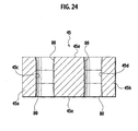
- a linkage mechanism 40K of this modification includes an expanded-diameter portion 80 at axial ends of the bearing holes 45c, 45d.
- the diameter is expanded at certain curvature, at a curvature that gradually increases, or at a curvature that increases in stages. Accordingly, a similar effect to the crowned linking pins 46, 47 can be obtained.
- this modification when the linking pins 46, 47 tilt maximally within a permissible range in a clearance in the bearing holes 45c, 45d, the increased contact area between the linking pins 46, 47 and the bearing holes 45c, 45d at the edges prevents themselves from lockingly diging into each other.
- the rectangular-shaped linkage member 45 is inserted to the slit 41s (between the arms 41, 41) of the rotor 21 and the slit 43s (between the arms 43, 43) of the swash plate.
- a single arm 41 extending form the rotor 21 and a single arm 43 extending form the swash plate 24 may be inserted into slits 45s, 45s of an H-shaped linkage member 45D.
- the first linking pin may be rotatably supported by each arms of the rotating member and the linkage member and the second linking pin may be supported by each arms of the rotating member and the linkage member.
- each bearing hole may be a bottomed hole.
- the first linking pin may be formed integrally with one of the arms of the rotating member or the linkage member
- the second linking pin may be formed integrally with one of the arm of the tilting member and the linkage member
- Fig. 29 shows a linkage mechanism as a comparative example.
- First ends of the pair of link arms 142A, 142B are rotatably connected to the pair of rotor arms 145, 146 by the first linking pin 143 and the second ends of the pair of link arms 142A, 142B are rotatably connected to the swash plate arms 147 by the second linking pin 144.
- the link arms 142A, 142B rotates about the linking pin 143 with respect to the rotor arms 145, 146 and the swash plate arms 147 rotates about the linking pin 144 with respect to the link arms 142A, 142B.
- an inclination angle of the swash plate 141 is made to be varied with respect to a drive shaft (not shown).
- the swash plate 24 is composed of a swash plate body 26 and a hub 25 which are made of different materials; however, a swash plate 24 may be integrally formed in the present invention.
- a swash-type swash plate is used; however, a wobble-type swash plate may be employed in the present invention.
- the linkage mechanism according to the present invention can be applied not only to compressors but also as a linkage mechanism in other devices. Further, the compressor according to the present invention can be applied to various fields, for example, as a compressor for a refrigeration cycle to compress refrigerant, or as a compressor for compressing gas such as air.
Landscapes
- Engineering & Computer Science (AREA)
- Mechanical Engineering (AREA)
- General Engineering & Computer Science (AREA)
- Manufacturing & Machinery (AREA)
- Compressors, Vaccum Pumps And Other Relevant Systems (AREA)
Abstract
Description
- The present invention relates to a linkage mechanism capable of relative rotating as transferring rotary torque and a variable displacement compressor using the linkage mechanism.
- A variable displacement compressor includes a drive shaft, a rotor which is fixed to the drive shaft and rotates integrally with the drive shaft, and a swash plate which is attached to the drive shaft via a slidable hinge ball and is tiltable with respect to the drive shaft. Piston stroke is changed by changing the inclination angle of the swash plate so as to change the discharging amount. In order to change the inclination angle of the swash plate as transferring torque from the rotor to the swash plate, a linkage mechanism is provided between the rotor and the swash plate (see, for example,
Japanese Patent Application Laid-Open Publications No. 2003-172417 No. 10-176658 - A linkage mechanism described in the Publication
No. 2003-172417 includes a pair of rotor arms which extend from a rotor toward a swash plate and face to each other, a single swash plate arm which extends from the swash plate toward the rotor, and a link whose first end is linked to the rotor arms by a first linking pin and second end is linked to the swash plate arm by a second linking pin. - The first end of the link is inserted between the pair of rotor arms of the rotor and linked to the rotor arms by the first linking pin. The second end of the link includes a pair of link arms facing each other, the swash plate arm is inserted between the link arms. In such a condition, the second end of the link is linked to the swash plate arm by a second linking pin. In other words, the swash plate arm is sandwiched by the pair of link arms provide at the second end of the link and the first end of the link is sandwiched by the pair of rotor arms. These five arms are stacked in the torque transfer direction.
- According to a linkage mechanism described in Publication
No. 10-176658 - An object of the present invention is to provide a linkage mechanism with improved durability and a variable displacement compressor using the linkage mechanism.
- The first aspect of the present invention is a linkage mechanism including: a rotating member fixed to a drive shaft and rotating integrally with the drive shaft; a tilting member slidably attached to the drive shaft and being tiltable with respect to the drive shaft; a pair of arms extending from the rotating member toward the tilting member and facing each other in a rotary torque transfer direction; a pair of arms extending form the tilting member toward the rotating member and facing each other in the rotary torque transfer direction; and a linkage member inserted between the pair of arms of the rotating member that face each other and between the pair of arms of the tilting member that face each other.
- According to the structure, comparing to a conventional technique including five arms in the torque transfer direction, the first aspect of the present invention includes three arms (in the side of the rotating member, there are three arms including the pair of arms of the rotating member and the linkage member inserted therebetween) (in the side of the tilting member, there are three arms including the pair arms of the tilting member and the linkage member inserted therebetween). Accordingly, the torque durability of the linkage mechanism can be improved since each member is made thicker in the torque transfer direction without increasing the size of the linkage mechanism as a whole, comparing to conventional structures (see, for example,
Japanese Patent Application Laid-Open Publications No. 2003-172417 No. 10-176658 - If it is required to reduce the size of the linkage mechanism in the torque transfer direction according to layout restrictions due to a request for downsizing devices, the linkage mechanism can be significantly downsized as maintaining sufficient thickness of each member in torque transfer direction, comparing to conventional techniques.
- As a preferable embodiment of the first aspect of the present invention, one end of the linkage member may be rotatably linked to the pair of arms of the rotating member by the first linking pin and the other end of the linkage member may be rotatably linked to the pair of arms of the tilting member by the second linking pin.
- A distance between the pair of arms of the rotating member and a distance between the pair of arms of the tilting member may be formed in the same size.
- According to this structure, the linkage member can be formed in a simple rectangular shape so that one end is inserted between the pair of arms of the rotating member and the other end is inserted between the pair of arms of tilting member. As a result, since complicated cutting works are not required in a manufacturing process of the linkage member, the manufacturing cost of the linkage member can be significantly reduced. For example, when the linkage member is made of aluminum, it can be made by extruding.
- The first linking pin and the second linking pin may have the same diameter and length.
- According to this structure, a pin can be used as the first linking pin and the second linking pin. Thus, the manufacturing cost of the linkage mechanism can be reduced. For example, since a manufacturing die can be used for both of the first linking pin and the second linking pin, the number of necessary dies can be reduced. Further, there is an advantage such that load of workers can be reduced since they do not need to distinguish the storing locations of the first linking pin and the second linking pin in an assembling process of the linkage mechanism.
- The second aspect of the present invention is a linkage mechanism including: a rotating member fixed to a drive shaft and rotating integrally with the drive shaft; a tilting member slidably attached to the drive shaft and being tiltable with respect to the drive shaft; an arm extending from the rotating member toward the tilting member; an arm extending form the tilting member toward the rotating member; and a linkage member provided between the arm of the rotating member and the arm of the tilting member. A slit is provided to one of the arm of the rotating member and one end of the linkage member, the other of the arm of the rotating member and the one end of the linkage member is inserted into the slit, the arm of the rotating member and the one end of the linkage member are rotatably connected each other by a first linking pin in a condition that the other is inserted into the one. A maximum inclination angle of the linkage member relative to the arm of the rotating member corresponds to a maximum inclination angle of the first linking pin in a bearing clearance between the first linking pin and a bearing hole for the first linking pin.
- According this structure, when the linkage member tilts maximally relative to the arms of rotating member, the portion inserted in the slit contacts with only one of the opposite surfaces of the slit. Accordingly, unlike conventional structures, the portion inserted in the slit does not lockingly dig into the opposite surfaces of the slit at two points.
- As a preferable embodiment of the first aspect of the present invention, the first linking pin may be fixed to a fixing hole provided to one of the arms of the rotating member and the linkage member and rotatably supported by the bearing hole provided to the other of the arms of the rotating member and the linkage member.
- According to this structure, the design of the linkage mechanism becomes easy comparing to such a structure in which the first linking pin is rotatably supported by bearing holes provided to the arms of the rotating member and the linkage member respectively.
- The third aspect of the present invention is a linkage mechanism including a rotating member fixed to a drive shaft and rotating integrally with the drive shaft; a tilting member slidably attached to the drive shaft and being tiltable with respect to the drive shaft; an arm extending from the rotating member toward the tilting member; an arm extending form the tilting member toward the rotating member; and a linkage member provided between the arm of the rotating member and the arm of the tilting member. A slit is provided to one of the arm of the tilting member and the other end of the linkage member, the other of the arm of the tilting member and the other end of the linkage member inserted into the slit, the arm of the tilting member and the other end of the linkage member are rotatably connected each other by a second linking pin. A maximum inclination angle of the linkage member relative to the arm of the tilting member corresponds to a maximum inclination angle of the second linking pin in a bearing clearance between the second linking pin and a bearing hole for the second linking pin.
- According this structure, when the linkage member tilts maximally relative to the arms of tilting member, the portion inserted in the slit contacts with only one of the opposite surfaces of the slit. Accordingly, unlike conventional structures, the portion inserted in the slit does not lockingly dig into the opposite surfaces of the slit at two points.
- As a preferable embodiment of the present invention, the second linking pin may be fixed to a fixing hole provided one of the arms of the tilting member and the linkage member and supported by the bearing hole provided to the other of the arms of the tilting member and the linkage member.
- According to this structure, the design of the linkage mechanism becomes easy comparing to such a structure in which the second linking pin is rotatably supported by bearing holes provided to the arms of the tilting member and the linkage member respectively.
- As a preferable embodiment according to the second and third aspects of the present invention, the linking pin may include a reduced-diameter portion, at axial ends, where the diameter is reduced at a certain curvature, at a curvature that gradually increases, or a curvature that increases in stages.
- According to this structure, a similar effect to crowned linking pins can be obtained. Namely, when the linking pins tilts maximally within bearing clearances in the bearing holes, the reduced-diameter portion provided at an axial end of the linking pin prevents point-contacts between the linking pins and the bearing holes.
- Further, the bearing hole may include an expanded-diameter portion, at axial ends, where the diameter is enlarged at a certain curvature, at a curvature that gradually increases, or at a curvature that increases in stages.
- According to this structure, a similar effect to crowned linking pins can be obtained. Namely, when the linking pins tilts maximally within baring clearances in the bearing holes, the expanded-diameter portion provided at an axial end of the bearing hole prevents point-contacts between the linking pins and the bearing holes.
- Further, the slit may be provided to the arm of the rotating member and an end of the linkage member is inserted into the slit, and the slit may be provided to the arm of the tilting member and the other end of the linkage member inserted into the slit.
- In other words, the aspects of the present invention may have a pair of arms that extend from the rotating member toward the tilting member and face each other across the slit, a pair of arms that extend from the tilting member toward the rotating member and face each other across the slit, and a linkage member that is inserted between the pair of arms of the rotating member and between the pair of arms of the tilting member.
- Unlike a conventional technique including five arms in the torque transfer direction, the present invention includes three arms (in the side of the rotating member, there are three arms including the arms of the rotating member and the linkage member inserted therebetween) (in the side of the tilting member, there are three arms including the arms of the tilting member and the linkage member inserted therebetween). Accordingly, the torque durability of the linkage mechanism can be improved since the each member is made thicker in the torque transfer direction without increasing the size of the linkage mechanism as a whole, comparing to conventional structures. If it is required to reduce the size of the linkage mechanism in the torque transfer direction according to layout restrictions due to a request for downsizing devices, the linkage mechanism can be significantly downsized as maintaining sufficient thickness of each member in torque transfer direction, comparing to conventional techniques.
- Further, a width of the slit (between the pair of arms) of the rotating member and a width of the slit (between the pair of arms) of the tilting member may be formed in same width.
- According to this structure, since the width of the slit in the rotating member and the width of the slit in the tilting member are formed the same, the linkage member whose one end is inserted into the slit of the rotating member and whose other end is inserted into the slit of the tilting member can be formed in a simple rectangular shape. As a result, since complicated cutting works are not required in a manufacturing process of the linkage member, the manufacturing cost of the linkage member can be significantly reduced. For example, when the linkage member is made of aluminum, it can be made by extruding.
- Further, the first linking pin and the second linking pin may have the same diameter and length.
- According to this structure, since the first linking pin and the second linking pin have the same diameter and length, a pin can be used as the first linking pin and the second linking pin. Accordingly, the manufacturing cost of the linkage mechanism can be reduced. For example, since a die can be used for both of the first linking pin and the second linking pin, the number of necessary dies can be reduced. Further, there is an advantage such that load of workers can be reduced since they do not need to distinguish the storing locations of the first linking pin and the second linking pin in an assembling process of the linkage mechanism.
-
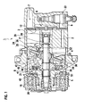
- Fig. 1 is a cross-sectional view showing a variable displacement compressor of a first embodiment;
- Fig. 2 is an explanatory view of a full stroke condition of the variable displacement compressor;
- Fig. 3 is an explanatory view of a middle stroke condition of the variable displacement compressor;
- Fig. 4 is an explanatory view of a no-stroke condition of the variable displacement compressor;
- Fig. 5 is a perspective view showing a linkage mechanism of the variable displacement compressor;
- Fig. 6 is a side view showing the linkage mechanism of the variable displacement compressor having a cross-section taken along line VI-VI in Fig. 2;
- Fig. 7 is an enlarged sectional view showing the linkage mechanism;
- Fig. 8 is a side view showing a rotor;
- Fig. 9 is a vertical sectional view showing the rotor;
- Fig. 10(a) is a side view showing a linkage member and Fig. 10(b) is a cross-sectional view taken along
line 10b-10b in Fig. 10(a); - Fig. 11 is a side view showing a hub of a swash plate;
- Fig. 12 is a vertical sectional view showing the hub of the swash plate;
- Fig. 13 is an enlarged sectional view showing a modification of the linkage mechanism;
- Fig. 14 is an enlarged sectional view showing another modification of the linkage mechanism;
- Fig. 15 is a side view showing a linkage mechanism of a second embodiment;
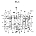
- Fig. 16 is an enlarged sectional view showing the linkage mechanism;
- Fig. 17 is a cross-sectional view showing a first modification of the linkage mechanism according to the second embodiment;
- Fig. 18 is a side view showing a linking pin used in the linkage mechanism of Fig. 17;
- Fig. 19 is an enlarged view of the part X shown in Fig. 18;
- Fig. 20 is a cross-sectional view showing a second modification of the linkage mechanism according to the second embodiment;
- Fig. 21 is an enlarged sectional view showing the linkage mechanism of Fig. 20;
- Fig. 22 is a sectional view showing a linkage mechanism of the third embodiment;
- Fig. 23 is a sectional view showing a modification of the linkage mechanism according to the third embodiment;
- Fig. 24 is a sectional view of the linkage member shown in Fig. 23;
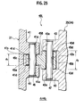
- Fig. 25 is a view showing a modification of the linkage mechanism according to the second embodiment and the third embodiment;
- Fig. 26 is a view showing a modification of the linkage mechanism of the second embodiment and the third embodiment;
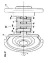
- Fig. 27 is a view showing a modification of the linkage mechanism according to the second and third embodiments;
- Fig. 28 is a view showing a modification of the linkage mechanism according to the second and third embodiments; and
- Fig. 29 is a view showing an example of a conventional linkage mechanism.
- A variable displacement compressor and a linkage mechanism used in the variable displacement compressor of embodiments of the present invention will be described with reference to the accompanying drawings.
- As shown in Fig. 1, a compressor 1 of the first embodiment is a swash plate type variable displacement compressor. The variable displacement compressor 1 includes a cylinder block 2 having a plurality of cylinder bores 3 placed evenly spaced apart in a circumferential direction, a front housing 4 attached to a front end of the cylinder block 2 and defining a crank chamber 5 with the cylinder block 2, and a rear housing 6 attached to a rear end of the cylinder block 2 via a valve plate 9 and having a suction chamber 7 and a discharge chamber 8 therein. The cylinder block 2, the front housing 4, and the rear housing 6 are fixedly connected to one another by a plurality of bolts B.
- The valve plate 9 is formed with a suction port (not shown) that communicates with the cylinder bore 3 and the suction chamber 7, and a
discharge port 12 that communicates with the cylinder bore 3 and the discharge chamber 8. - A valve system (not shown) adapted to open or close the suction port 11 is provided on the valve plate 9 at the cylinder block side. On the other hand, A valve system (not shown) adapted to open or close the
discharge port 12 is provided on the valve plate 9 at the rear housing side. A gasket is interposed between the valve plate 9 and the rear housing 6 for providing an airtight seal between the suction chamber 7 and the discharge chamber 8. - A drive shaft S is supported by
bearings - The crank chamber 5 accommodates, a
rotor 21 as a "rotating member" fixed to the drive shaft S, ahinge ball 22 slidably attached to the drive shaft S, and aswash plate 24 as a "tilting member" tiltably attached to thehinge ball 22. Theswash plate 24 includes ahub 25 tiltably and rotatably attached to thehinge ball 22 and aswash plate body 26 fixed to aboss segment 25a of thehub 25. - A
piston 29 is slidably contained in each cylinder bore 3, and engaged with theswash plate body 26 of theswash plate 24 via a pair of hemispherical-shapedshoes - A
linkage mechanism 40 is provided between therotor 21 as a rotating member and thehub 25 of theswash plate 24 as a tilting member. Thelinkage mechanism 40 transfers rotary torque from therotor 21 to theswash plate 24 as allowing the inclination angle of theswash plate 24 to change. Thelinkage mechanism 40 will hereinafter be described in detail. - The inclination angle of the
swash plate 24 reduces when thehinge ball 22 moves toward the cylinder block 2. On the other hand, the inclination angle of theswash plate 24 increases when thehinge ball 22 moves away from the cylinder block 2. - When the drive shaft S rotates, the
rotor 21 rotates integrally with the drive shaft S. The rotation of therotor 21 is transferred to theswash plate 24 via thelinkage mechanism 40. The rotation of theswash plate 24 is converted into a reciprocating movement of thepistons 29 via the pairs ofpiston shoes pistons 29 reciprocate in the cylinder bores 3. By the reciprocating movements of thepistons 29, cooling medium is sucked in from the suction chamber 7 into the cylinder bores 3 through the suction ports 11 of the valve plate 9, and compressed in the cylinder bores 3, and discharged to the discharge chamber 8 through thedischarge ports 12 of the valve plate 9. - Changing the inclination angle of the
swash plate 24 changes the piston stroke so as to change the amount of the discharge capacity. More particularly, changing pressure difference (pressure balancing) between the crank chamber pressure Pc in back of thepiston 29 and the suction chamber pressure Ps in front of thepiston 29 changes the inclination angle of theswash plate 24 to change the piston stroke. Thus, the variable displacement compressor includes a pressure control mechanism having a gas extraction passage (not shown) that allows the crank chamber 5 to communicate with the suction chamber 7, an gas supply passage (not shown) that allows the crank chamber 5 to communicate with the discharge chamber 8, and acontrol valve 33 that is provided in the midstream of the gas supply passage to open and close the gas supply passage. Here, Fig. 2 shows the inclination angle of theswash plate 24 in a full stroke mode, Fig. 3 shows the inclination angle of theswash plate 24 in a middle stroke mode, and Fig. 4 shows the inclination angle of theswash plate 24 in a destroke mode. - The
linkage mechanism 40 will be described in detail. Fig. 5 is a perspective view showing alinkage mechanism 40, Fig. 6 is a side view showing thelinkage mechanism 40 with a cross-section taken along line VI-VI in Fig. 2, and Fig. 7 is an enlarged sectional view showing thelinkage mechanism 40. Fig. 8 is a side view showing therotor 21, Fig. 9 is a vertical sectional view showing therotor 21, Figs. 10(a) and 10(b) are views showing the linkage member, Fig. 11 is a side view showing thehub 25 of theswash plate 24, and Fig. 12 is a vertical sectional view showing thehub 25 of theswash plate 24. - As shown in Figs. 5 and 6, the
linkage mechanism 40 includes a pair ofarms rotor 21 toward thehub 25 and face each other in the rotary torque transfer direction, a pair ofarms hub 25 toward therotor 21 and face each other in the rotary torque transfer direction, and alinkage member 45 that is inserted between the pair ofopposite arms rotor 21 and between the pair ofopposite arms hub 25. - A
first end 45a of thelinkage member 45 is pivoted to the pair ofarms rotor 21 by afirst linking pin 46 extending in the rotary torque direction. Thesecond end 45b of thelinkage member 45 is pivoted to the pair ofarms hub 25 by asecond linking pin 47 extending in the rotary torque direction. - As shown in Fig. 7, each of the
arms rotor 21 is formed with a throughhole 41a to which thefirst linking pin 46 is rotatably inserted. Thefirst end 45a of thelinkage member 45 is formed with a throughhole 45c, coaxially with the throughhole 41a, to which thefirst linking pin 46 is inserted with force. Each of thearms hub 25 is formed with a throughhole 43a to which thesecond linking pin 47 is rotatably inserted. Thesecond end 45b of thelinkage member 45 is formed with a throughhole 45d, coaxially with the throughhole 43a, to which thefirst linking pin 46 is inserted with force. Thefirst linking pin 46 and thesecond linking pin 47 have the same diameter and length. - The distance d1 between the pair of
arms inner surfaces arms 41, 41) and the distance d2 between the pair ofarms inner surfaces arms 43, 43) are formed the same. The width d0 of the linkage member 45 (that is, distance d0 betweenouter surfaces arms rotor 21 and the distance d2 between thearms hub 25. Both of theouter faces linkage member 45 are formed flat without any unevenness. - With the above described structure, the present embodiment brings about the following effects.
- Firstly, the structure of the present embodiment includes a pair of
arms rotor 21 as a "rotating member" toward ahub 25 of aswash plate 24 as a "tilting member" and face each other in the rotary torque transfer direction, a pair ofarms hub 25 toward therotor 21 and face each other in the rotary torque transfer direction, and alinkage member 45 that is inserted between the pair of facingarms rotor 21 and between the pair of facingarms hub 25. Comparing to conventional structures (see, for example,Japanese Patent Application Laid-Open Publications No. 2003-172417 No. 10-176658 rotor 21, there are three arms including the pair ofarms rotor 21 and thelinkage member 45 inserted therebetween) (in the side ofhub 25, there are three arms including the pair ofarms hub 25 and thelinkage member 45 inserted therebetween). - With this structure, the torque durability of the
linkage mechanism 40 can be improved since each of themembers linkage mechanism 40 as a whole. When layout restrictions corresponding to a downsizing request require to reduce the size of thelinkage mechanism 40 in the torque transfer direction , thelinkage mechanism 40 can be significantly downsized as maintaining sufficient thickness of eachmember - Secondly, since the width d1 between the pair of
arms rotor 21 and the width d2 between the pair ofarms hub 25 are formed the same, thelinkage member 45 whosefirst end 45a is inserted between the pair ofarms rotor 21 andsecond end 45b is inserted between the pair ofarms hub 25 can be formed in a simple rectangular shape. As a result, complicated cutting works are not required when manufacturing thelinkage member 45. The manufacturing cost of thelinkage member 45 can be significantly reduced. For example, when the linkage member is made of aluminum, it can be made by extruding. - Thirdly, the
first linking pin 46 and thesecond linking pin 47 have the same diameter and length, so that a pin can be used as thefirst linking pin 46 and thesecond linking pin 47. Accordingly, the manufacturing cost of thelinkage mechanism 40 can be reduced. For example, a manufacturing die can be used for both of thefirst linking pin 46 and thesecond linking pin 47, so that the number of necessary dies can be reduced. Further, workers do not need to distinguish thefirst linking pin 46 and thesecond linking pin 47 to store on a working bench in an assembling process of thelinkage mechanism 40, so that work load can be reduced. - According to the first embodiment, the width d1 between the
arms rotor 21 and the width d2 between thearms hub 25 are formed to be the same width and thelinkage member 45 is formed in a rectangular shape; however, in the present invention, the width d1 between the arms of therotor 21 and the width d2 between the arms of the hub may be formed different and thelinkage member other linkage mechanisms - According to the
linkage mechanism 40B shown in Fig. 13, the width d2 between a pair ofarms hub 25 is formed larger than the width d1 between a pair ofarms rotor 21. Further, the width (≒ d1) of aportion 45a which is to be inserted between thearms rotor 21 is smaller than the width (≒ d2) of aportion 45b which is to be inserted between thearms hub 25. Accordingly, thelinkage member 45B is formed with steps. Further, the length of thesecond linking pin 47B is made longer than the length of thefirst linking pin 46B. - Similar to the
linkage mechanism 40 of the first embodiment, thelinkage mechanism 40B shown in Fig. 13 includes a pair ofarms rotor 21 as a "rotating member" toward ahub 25 of aswash plate 24 as a "tilting member" and face each other in the rotary torque transfer direction, a pair ofarms hub 25 toward therotor 21 and face each other in the rotary torque transfer direction, and alinkage member 45B that is inserted between the facingarms rotor 21 and between the facingarms hub 25. Unlike the conventional techniques (see, for example,Japanese Patent Application Laid-Open Publications No. 2003-172417 No. 10-176658 linkage mechanism 40B includes three arms (in the side of therotor 21, there are three arms including thearms rotor 21 and thelinkage member 45B inserted therebetween) (in the side ofhub 25, there are three arms including thearms hub 25 and thelinkage member 45B inserted therebetween). - With this structure, each of the members (41B, 43B, 45B) can be made thicker in the torque transfer direction than the conventional structures so that the torque durability of the
linkage mechanism 40B can be improved without increasing the size of thelinkage mechanism 40B. - If it is required to reduce the size of the
linkage mechanism 40B in the torque transfer direction according to layout restrictions due to a downsizing request, thelinkage mechanism 40B can be significantly downsized as maintaining sufficient thickness of each member (41B, 43B, 45B) in torque transfer direction, comparing to conventional structures. - According to the
linkage mechanism 40C shown in Fig. 14, the width d2 between a pair ofarms hub 25 is made smaller than the width d1 between a pair ofarms rotor 21. Further, the width (≒ d1) of aportion 45a which is to be inserted between thearms rotor 21 is made larger than the width (≒ d2) of aportion 45b which is to be inserted between thearms hub 25. Accordingly, thelinkage member 45C is formed with steps. Thesecond linking pin 47B is made shorter in length than thefirst linking pin 46B. - Similar to the
linkage mechanism 40 of the first embodiment, thelinkage mechanism 40C shown in Fig. 14 also includes a pair ofarms rotor 21 as a "rotating member" toward ahub 25 of aswash plate 24 as a "tilting member" and face each other in the rotary torque transfer direction, a pair ofarms hub 25 toward therotor 21 and face each other in the rotary torque transfer direction, and alinkage member 45C that is inserted between the facingarms rotor 21 and between the facingarms hub 25. Unlike the conventional structures (see, for example,Japanese Patent Application Laid-Open Publications No. 2003-172417 No. 10-176658 linkage mechanism 40C includes three arms (in the side of therotor 21, there are three arms including thearms rotor 21 and thelinkage member 45C inserted therebetween) (in the side ofhub 25, there are three arms including thearms hub 25 and thelinkage member 45C inserted therebetween). - With this structure, if the
linkage mechanism 40C is made in the same size as the conventional linkage mechanism, each of the members (41C, 43C, 45C) is made thicker in the torque transfer direction than the conventional structures so that the torque durability of thelinkage mechanism 40C is improved. When it is required to reduce the size of thelinkage mechanism 40C in the torque transfer direction according to layout restrictions due to a downsizing request, thelinkage mechanism 40C can be significantly downsized as maintaining sufficient thickness of each member (41C, 43C, 45C) in torque transfer direction, comparing to conventional structures. - As described above, according to the first embodiment, a linkage mechanism includes a pair of arms that extend from a rotating member toward a tilting member and face each other in the rotary torque transfer direction, a pair of arms that extend from the tilting member toward the rotating member and face each other in the rotary torque transfer direction, and a linkage member that is inserted between the facing arms of the rotating member and between the facing arms of the tilting member. Unlike the conventional techniques (see, for example,
Japanese Patent Application Laid-Open Publications No. 2003-172417 No. 10-176658 Japanese Patent Application Laid-Open Publications No. 2003-172417 No. 10-176658 - A
linkage mechanism 40F of the second embodiment will be described in detail. Fig. 15 is a side view showing thelinkage mechanism 40F of the second embodiment and Fig. 16 is an enlarged sectional view showing thelinkage mechanism 40F. - As shown in Fig. 15, the
linkage mechanism 40F includes a pair ofarms rotor 21 toward aswash plate 24 and face each other in the rotary torque transfer direction across aslit 41s, a pair ofarms swash plate 24 toward therotor 21 and face each other in the rotary torque transfer direction across aslit 43s, and alinkage member 45 that is inserted into theslit 41s of the rotor 21 (that is, between thearms 41, 41) and into theslit 43s of the swash plate 24 (that is, between thearms 43, 43). - A
first end 45a of thelinkage member 45 is pivotally connected to thearms rotor 21 by afirst linking pin 46 which extends in the rotary torque direction, and asecond end 45b of thelinkage member 45 is pivotally connected to thearms swash plate 24 by asecond linking pin 47 which extends in the rotary torque direction. - As shown in Figs. 15 and 16, the pair of
arms rotor 21 havebearing holes 41a for rotatably supporting thefirst linking pin 46 and thefirst end 45a of thelinkage member 45 has a fixinghole 45c to which thefirst linking pin 46 is inserted with force. The pair ofarms swash plate 24 havebearing holes 43a for rotatably supporting thesecond linking pin 47 and thesecond end 45b of thelinkage member 45 has a fixinghole 45d to which thesecond linking pin 47 is inserted with force. Thefirst linking pin 46 and thesecond linking pin 47 have same diameter and length. - The width d1 of the
slit 41s of the rotor 21 (that is, the width betweeninner surfaces arms slit 43s of the swash plate 24 (that is, the width betweeninner surfaces arms linkage member 45 is formed in a rectangular shape and itsouter surfaces outer surfaces slit 41s of therotor 21 and the width d2 of theslit 43 of theswash plate 24. - According to the second embodiment, as shown in Fig. 16, a clearance Δd (=d1-d0) between the
slit 41s of therotor 21 and thelinkage member 45 is set larger than a predetermined value. With this structure, a maximum inclination angle of thelinkage member 45 relative to thearms first linking pin 46 and thebearing holes linkage member 45 tilts maximally relative to thearms rotor 21 within a permissible range in the clearance Δd1 (=d21-d11) between thefirst linking pin 46 and thebearing holes linkage member 45 does not contact with both of the facingsurfaces slit 41s but contacts at only a point C1 shown in Fig. 16. - According to the second embodiment, the clearance Δd (=d2-d0) between the
slit 43s of theswash plate 24 and thelinkage member 45 is set larger than a predetermined value. Accordingly, the maximum inclination angle of thelinkage member 45 relative to thearms 43 of the swash plate equals to a maximum inclination angle of thesecond linking pin 47 permissible in a bearing clearance Δd2 (=d22-d12) between thesecond linking pin 47 and thebearing holes linkage member 45 tilts maximally toward thearms second linking pin 47 and thebearing holes linkage member 45 does not contact with both of the facingsurfaces slit 43s but contacts at only a point (that is, the point C2 shown in Fig. 16). - With the above described structure, the second embodiment brings about the following effects.
- (1)According to the second embodiment, a
slit 41s for receiving one ofarms 41 of a rotatingmember 21 and afirst end 45a of a linkage member 45 (arms 41 of a rotating member, in this embodiment) is provided to the other of thearms 41 of the rotatingmember 21 and thefirst end 45a of the linkage member 45 (thefirst end 45a of thelinkage member 45, in this embodiment) and they are pivotably connected each other by afirst linking pin 46 in a state that the other of them is inserted into the one of them. A maximum inclination angle of thelinkage member 45 relative to thearms 41 of the rotating member equals to a maximum inclination angle of thefirst linking pin 46 permissible in a bearing clearance Δd1 (=d21-d11) between thefirst linking pin 46 and itsbearing holes linkage member 45 tilts maximally relative to thearms 41 of rotating member within a permissible range in the clearance Δd1 (=d21-d11) between thefirst linking pin 46 and thebearing holes linkage member 45 inserted in theslit 41s (thefirst end 45a of thelinkage member 45, in this embodiment) does not contact with both of theopposite surfaces slit 41s simultaneously but contacts with only one 41d of theopposite surfaces linkage member 45 does not lockingly dig into at two points. - (2)According to the second embodiment, a
slit 43s for receiving one ofarms 43 of a tiltingmember 25 and asecond end 45b of the linkage member 45 (arms 43 of a tilting member, in this embodiment) is provided to the other of thearms 43 of the tiltingmember 25 and thesecond end 45b of the linkage member 45 (thesecond end 45b of thelinkage member 45, in this embodiment) and they are pivotably connected each other by asecond linking pin 47 in a state that the other 45 of them is inserted into the one 43 of them. A maximum inclination angle of thelinkage member 45 relative to thearms 43 of the tilting member equals to a maximum inclination angle of thesecond linking pin 47 permissible in a bearing clearance Δd2 (=d22-d12) between thesecond linking pin 47 and thebearing holes linkage member 45 tilts maximally relative to thearms 43 of tilting member within a permissible range in the clearance Δd2 (=d22-d12) between thesecond linking pin 47 and thebearing holes linkage member 45 inserted in theslit 43s (thesecond end 45b of thelinkage member 45, in this embodiment) does not contact with both of theopposite surfaces slit 43s simultaneously but contacts with only one 43d of theopposite surfaces linkage member 45 does not lockingly dig into at two points. - (3)According to the second embodiment, the
first linking pin 46 is fixed to a fixinghole 45c formed in one of thearms 41 of the rotating member and the linkage member 45 (linkage member 45, in this embodiment) and supported by a bearing holes 41a, 41a formed in the other of thearms 41 of the rotating member and the linkage member 45 (thearms 41 of the rotating member, in this embodiment). Thus, unlike cases that the bearing holes are provided to the arms of the rotating member and the linkage member, one of the holes is made as a fixinghole 45c so that the design of the linkage mechanism becomes easier. - (4)According to the second embodiment, the
second linking pin 47 is fixed to afixing hole 45d formed in one of thearms 43 of the tilting member and the linkage member 45 (linkage member 45, in this embodiment) and rotatably supported by bearingholes arms 43 of the tilting member and the linkage member 45 (thearms 43 of the tilting member, in this embodiment). Thus, unlike cases that bearing holes are provided to the arms of the tilting member and the linkage member, one of the holes is made as a fixinghole 45d so that the design of the linkage mechanism becomes easier. - (5)According to the second embodiment, the
first end 45a of thelinkage member 45 is inserted into theslit 41s which is provided to thearms 41 of the rotating member, and thesecond end 45b of thelinkage member 45 is inserted into theslit 43s which is provided to thearms 43 of the tilting member. In other words, the second embodiment has the pair ofarms member 21 toward the tiltingmember 25 and face each other across theslit 41s, the pair ofarms member 25 toward the rotatingmember 21 and face each other across theslit 43s, and alinkage member 45 that is inserted between thearms arms - Therefore, unlike the conventional structures (see, for example,
Japanese Patent Application Laid-Open Publications No. 2003-172417 No. 10-176658 arms linkage member 45 inserted therebetween) (in the side of the tilting member, there are three arms including thearms linkage member 45 inserted therebetween). - With this structure, even when each of the members (41, 43, 45) is made thicker in the torque transfer direction in order to improve the torque durability of the
linkage mechanism 40F, the size of thelinkage mechanism 40F as a whole is not enlarged. If it is required to reduce the size of thelinkage mechanism 40F in the torque transfer direction according to layout restrictions, thelinkage mechanism 40F can be significantly downsized as maintaining sufficient thickness of each member (41, 43, 45) in torque transfer direction, comparing to conventional structures. - (6)According to the second embodiment, the width d1 of the
slit 41s of thearms slit 43s of thearms slit 41s of thearms slit 43s of thearms linkage member 45 can be made in a simple rectangular shape. As a result, complicated cutting works are not required when manufacturing thelinkage member 45, so that the manufacturing cost of thelinkage member 45 can be significantly reduced. For example, when the linkage member is made of aluminum, it can be made by extruding and the like. - (7)According to the second embodiment, the
first linking pin 46 and thesecond linking pin 47 have the same diameter and length. Accordingly, a pin can be used as thefirst linking pin 46 and thesecond linking pin 47 and the manufacturing cost of thelinkage mechanism 40F can be reduced. For example, since a manufacturing die can be used for both of thefirst linking pin 46 and thesecond linking pin 47, the number of necessary dies can be reduced. Further, workers do not need to distinguish thefirst linking pin 46 and thesecond linking pin 47 to sort on a working bench in an assembling process of thelinkage mechanism 40F, so that work load can be reduced. - Next, modifications of the second embodiment will be explained.
- Figs. 17 to 19 are views showing the first modification of the linkage mechanism according to the second embodiment.
- A
linkage mechanism 40G of the first modification includes reduced-diameter portions 60, at axial ends thereof, where the diameter is reduced at a certain curvature, at a curvature that gradually increases, or at a curvature that increases in stages. In other words, the linking pins 46, 47 are crowned. Here, reference "61" in Fig. 19 represents a linear portion located closer to the end than the curved reduced-diameter portion 60. According to this modification, when thelinkage member 45 tilts such that the linking pins 46, 47 tilt maximally within the bearing clearance of bearingholes bearing holes - Figs. 20 and 21 are views showing the second modification of the linkage mechanism according to the second embodiment.
- A
linkage mechanism 40H of the second modification includes expanded-diameter portions 70, at the axial ends of thebearing holes diameter portions 70 are expanded at certain curvature, at a curvature that gradually increases, or at a curvature that increases in stages. Accordingly, a similar effect to the crowned linkingpins bearing holes bearing holes - The third embodiment of the present invention will be explained with reference to Fig. 22.
- According to a
linkage mechanism 40J of the third embodiment,holes arms first linking pin 46 is inserted with force to be fixed thereto, and ahole 45c provided to alinkage member 45 is a bearing hole to which thefirst linking pin 46 is rotatably supported, in contrast to the second embodiment. And, holes 43a, 43a provided toarms second linking pin 47 is inserted with force to be fixed thereto, and anotherhole 45c provided thelinkage member 45 is a bearing hole to which thesecond linking pin 47 is rotatably supported, in contrast to the second embodiment. Therefore, the third embodiment can obtain similar effects to those of the second embodiment. - Figs. 23 and 24 are views showing a modification of the third embodiment.
- A
linkage mechanism 40K of this modification includes an expanded-diameter portion 80 at axial ends of the bearingholes pins holes holes - In the above described
linkage mechanism arms 41, 41) of therotor 21 and the width d2 of the slit 43S (between thearms 43, 43) of theswash plate 24 are formed to be the same width and thelinkage member 45 is formed in a rectangular shape. However, for example, as shown in alinkage mechanism 40L in Fig. 25 and alinkage mechanism 40M in Fig. 26, the width d1 of the slit 41S (that is, between the arms) of therotor 21 and the width d2 of the slit 43S (that is, between the arms) of the swash plate may be different andlinkage member - In the above described
linkage mechanism linkage member 45 is inserted to theslit 41s (between thearms 41, 41) of therotor 21 and theslit 43s (between thearms 43, 43) of the swash plate. However, for example, as shown in thelinkage mechanism 40N of Fig. 27, asingle arm 41 extending form therotor 21 and asingle arm 43 extending form theswash plate 24 may be inserted intoslits linkage member 45D. Further, for example, as shown in alinkage mechanism 40P of Fig. 28, asingle arm 43 extending from aswash plate 24 may be inserted in aslit 45s of asecond end 45b of a Y-shapedlinkage member 45 E and afirst end 45a of thelinkage member 45 may be inserted in to aslit 41s (betweenarms 41, 41) of arotor 21. - According to the above described second and third embodiments, if the portion inserted into the slit contacts with only one of the facing surfaces in the slit when a linkage member tilts maximally within a permissible range in a clearance between bearing holes and linking pins, the first linking pin may be rotatably supported by each arms of the rotating member and the linkage member and the second linking pin may be supported by each arms of the rotating member and the linkage member. In addition, each bearing hole may be a bottomed hole.
- Further, according to the second and third embodiments, the linking pins are inserted with force and fixed to the fixing holes; however, the linking pins may be fixed to the fixing holes by screws and the like.
- Further, according to the second and third embodiments, the first linking pin may be formed integrally with one of the arms of the rotating member or the linkage member, and the second linking pin may be formed integrally with one of the arm of the tilting member and the linkage member.
- Fig. 29 shows a linkage mechanism as a comparative example.
- A linkage mechanism shown in Fig. 29 includes a pair of
rotor arms rotor 140 toward aswash plate 141, a singleswash plate arm 147 extending from theswash plate 141 toward therotor 140, and a pair oflink arms arms rotor 140 is transferred to the swash plate. First ends of the pair oflink arms rotor arms first linking pin 143 and the second ends of the pair oflink arms swash plate arms 147 by thesecond linking pin 144. With this, thelink arms pin 143 with respect to therotor arms swash plate arms 147 rotates about the linkingpin 144 with respect to thelink arms swash plate 141 is made to be varied with respect to a drive shaft (not shown).
When the compressor is operative, a contact face between therotor arm 145 and thelink arm 142A and a contact face between thelink arm 142A and theswash plate arms 147 function as torque transferring faces, and also, as rotating-sliding faces. In other words, therotor arm 145 and thelink arm 142A slides and rotates with respect to one another under a large pressure of the rotary torque. Thelink arm 142A and theswash plate arm 147 also slide and rotate with respect to one another under a large pressure of the rotary torque Ft. Accordingly, when changing the inclination angle of theswash plate 141, the slide friction resistance at the contact between therotor arm 145 and thelink arm 142A becomes extremely high and the slide friction resistance at the contact between thelink arm 142A and theswash plate arm 147 also becomes extremely high. - Further, when the compressor is operative (when the drive shaft rotates), the
swash plate 141 receives compression reaction force Fp form a piston (not shown) connected to theswash plate 141. As shown in Fig. 29, since the compression reaction force Fp is applied to a position anterior to the linkage mechanism in the rotating direction, torsion load is given to theswash plate arms 147 in the Y direction in the figure. Accordingly, thelink 142 gets "stack" in theswash plate 141 at two points (C, C) and this causes a further increased slide friction resistance. - Unlike the linkage mechanism shown in Fig. 29, in the
linkage mechanisms linkage member 45 relative to thearms 41 of the rotating member equals to the maximum inclination angle of thefirst linking pin 46 in the bearing clearance Δd1(=d21-d11) between thefirst linking pin 46 and thebearing holes linkage member 45 maximally tilts wit respect to thearms 41 of the rotating member within a permissible range in the bearing clearance Δd1 (=d21-d11) between thefirst linking pin 46 and thebearing holes slit 41s (here, thefirst end 45a of the linkage member 45) contacts with only one of the facingsurfaces 41d and do not contact with the both of the facingsurfaces slit 41 at the same time. That is, unlike the linkage mechanism shown in Fig. 29, they will not lockingly dig into each other at two points. Therefore, the durability of thelinkage mechanisms - In the first to third embodiments, the
swash plate 24 is composed of aswash plate body 26 and ahub 25 which are made of different materials; however, aswash plate 24 may be integrally formed in the present invention. - In the, first to third embodiments, the
swash plate 24 is attached to the drive shaft S via asleeve 22; however, for example, a sleeveless structure in which theswash plate 24 is directly attached to the drive shaft S without a sleeve may be employed in the present invention. - In the first to third embodiments, a swash-type swash plate is used; however, a wobble-type swash plate may be employed in the present invention.
- Further, it will be appreciated that the present invention can be implemented with various modifications within the technical scope of the present invention.
- The linkage mechanism according to the present invention can be applied not only to compressors but also as a linkage mechanism in other devices. Further, the compressor according to the present invention can be applied to various fields, for example, as a compressor for a refrigeration cycle to compress refrigerant, or as a compressor for compressing gas such as air.
Claims (36)
- A linkage mechanism comprising:a rotating member fixed to a drive shaft and rotating integrally with the drive shaft;a tilting member slidably attached to the drive shaft and being tiltable with respect to the drive shaft;a pair of arms extending from the rotating member toward the tilting member and facing each other in a rotary torque transfer direction;a pair of arms extending form the tilting member toward the rotating member and facing each other in the rotary torque transfer direction; anda linkage member inserted between the pair of arms of the rotating member and between the pair of arms of the tilting member.
- The linkage mechanism according to claim 1, wherein one end of the linkage member is rotatably connected to the pair of arms of the rotating member by the first linking pin and the other end of the linkage member is rotatably connected to the pair of arms of the tilting member by the second linking pin.
- The linkage mechanism according to claim 1, wherein a distance between the pair of arms of the rotating member and a distance between the pair of arms of the tilting member are formed in a same size.
- The linkage mechanism according to claim 3, wherein the first linking pin and the second linking pin have the same diameter and length.
- A variable displacement compressor comprising:a drive shaft;a rotating member fixed to the drive shaft and rotating integrally with the drive shaft;a tilting member slidably attached to the drive shaft and being tiltable with respect to the drive shaft;a linkage mechanism linking the rotating member and the tilting member and transferring rotary torque of the rotating member to the tilting member as allowing a tilt of the tilting member to change; anda piston configured to reciprocate in a cylinder bores corresponding to rotary movement of the tilting member; whereinthe linkage mechanism includes:a pair of arms extending from the rotating member toward the tilting member and facing each other in a rotary torque transfer direction;a pair of arms extending form the tilting member toward the rotating member and facing each other in the rotary torque transfer direction; anda linkage member inserted between the pair of arms of the rotating member and between the pair of arms of the tilting member.
- The variable displacement compressor according to claim 5, wherein one end of the linkage member is rotatably connected to the pair of arms of the rotating member by the first linking pin and the other end of the linkage member is rotatably connected to the pair of arms of the tilting member by the second linking pin.
- The variable displacement compressor according to claim 5, wherein a distance between the pair of arms of the rotating member and a distance between the pair of arms of the tilting member are formed in the same size.
- The variable displacement compressor according to claim 7, wherein the first linking pin and the second linking pin have the same diameter and length.
- A linkage mechanism comprising:a rotating member fixed to a drive shaft and rotating integrally with the drive shaft;a tilting member slidably attached to the drive shaft and being tiltable with respect to the drive shaft;an arm extending from the rotating member toward the tilting member;an arm extending form the tilting member toward the rotating member; anda linkage member provided between the arm of the rotating member and the arm of the tilting member; whereina slit is provided to one of the arm of the rotating member and one end of the linkage member, the other of the arm of the rotating member and the end of the linkage member is inserted into the one, the arm of the rotating member and the one end of the linkage member are rotatably connected each other by a first linking pin; anda maximum inclination angle of the linkage member relative to the arm of the rotating member corresponds to a maximum inclination angle of the first linking pin in a bearing clearance between the first linking pin and a bearing hole for the first linking pin.
- The linkage mechanism according to claim 9, wherein the first linking pin is fixed to a fixing hole provided in one of the arms of the rotating member and the linkage member and rotatably supported in the bearing hole provided in the other of the arms of the rotating member and the linkage member.
- The linkage mechanism according to claim 9, wherein the linking pin includes a reduced-diameter portion, at axial ends, where the diameter is reduced at a certain curvature, at a curvature that gradually increases, or at a curvature that increases in stages.
- The linkage mechanism according to claim 9, wherein the bearing hole includes an expanded-diameter portion, at axial ends, where the diameter is enlarged at a certain curvature, at a curvature that gradually increases, or at a curvature that increases in stages.
- The linkage mechanism according to claim 9, wherein
the slit is provided to the arm of the rotating member and the one end of the linkage member is inserted into the slit; and
the slit is provided to the arm of the tilting member and the other end of the linkage member inserted into the slit. - The linkage mechanism according to claim 13, wherein a width of the slit in the rotating member and a width of the slit in the tilting member are formed in the same width.
- The linkage mechanism according to claim 9, wherein the first linking pin and the second linking pin have the same diameter and length.
- A linkage mechanism comprising:a rotating member fixed to a drive shaft and rotating integrally with the drive shaft;a tilting member slidably attached to the drive shaft and being tiltable with respect to the drive shaft;an arm extending from the rotating member toward the tilting member;an arm extending form the tilting member toward the rotating member; anda linkage member provided between the arm of the rotating member and the arm of the tilting member; whereina slit is provided to one of the arm of the tilting member and the other end of the linkage member, the other of the arm of the tilting member and the other end of the linkage member inserted into the one, the arm of the tilting member and the other end of the linkage member are rotatably connected each other by a second linking pin; anda maximum inclination angle of the linkage member relative to the arm of the tilting member corresponds to a maximum inclination angle of the second linking pin in a bearing clearance between the second linking pin and a bearing hole for the second linking pin.
- The linkage mechanism according to claim 16, wherein the second linking pin is fixed to a fixing hole provided to one of the arms of the tilting member and the linkage member and rotatably supported in the bearing hole provided to the other of the arms of the tilting member and the linkage member.
- The linkage mechanism according to claim 16, wherein the linking pin includes a reduced-diameter portion, at axial ends, where the diameter is reduced at a certain curvature, at a curvature that gradually increases, or at a curvature that increases in stages.
- The linkage mechanism according to claim 16, wherein the bearing hole includes an expanded-diameter portion, at axial ends, where the diameter is enlarged at a certain curvature, at a curvature that gradually increases, or at a curvature that increases in stages.
- The linkage mechanism according to claim 16, wherein
the slit is provided to the arm of the rotating member and one end of the linkage member is inserted into the slit; and
the slit is provided to the arm of the tilting member and the other end of the linkage member inserted into the slit. - The linkage mechanism according to claim 20, wherein a width of the slit in the rotating member and a width of the slit in the tilting member are formed in the same width.
- The linkage mechanism according to claim 16, wherein the first linking pin and the second linking pin have the same diameter and length.
- A variable displacement compressor comprising:a drive shaft;a rotating member fixed to the drive shaft and rotating integrally with the drive shaft;a tilting member slidably attached to the drive shaft and being tiltable with respect to the drive shaft;a linkage mechanism linking the rotating member and the tilting member and transferring rotary torque of the rotating member to the tilting member as allowing a tilt of the tilting member to change; anda piston configured to reciprocate in a cylinder bores corresponding to rotary movement of the tilting member; whereinthe linkage mechanism includes:an arm extending from the rotating member toward the tilting member;an arm extending form the tilting member toward the rotating member; anda linkage member provided between the arm of the rotating member and the arm of the tilting member; and whereina slit is provided to one of the arm of the rotating member and one end of the linkage member, the other of the arm of the rotating member and the one end of the linkage member into the one, the arm of the rotating member and the one end of the linkage member are rotatably connected each other by a first linking pin; anda maximum inclination angle of the linkage member relative to the arm of the rotating member corresponds to a maximum inclination angle of the first linking pin in a bearing clearance between the first linking pin and a bearing hole for the first linking pin.
- The variable displacement compressor according to claim 23, wherein the first linking pin is fixed to a fixing hole provided in one of the arms of the rotating member and the linkage member and rotatably supported in the bearing hole provided to the other of the arms of the rotating member and the linkage member.
- The variable displacement compressor according to claim 23, wherein the linking pin includes a reduced-diameter portion, at axial ends, where the diameter is reduced at a certain curvature, at a curvature that gradually increases, or at a curvature that increases in stages.
- The variable displacement compressor according to claim 23, wherein the bearing hole includes an expanded-diameter portion, at axial ends, where the diameter is enlarged at a certain curvature, at a curvature that gradually increases, or in stages.
- The variable displacement compressor according to claim 23, wherein
the slit is provided to the arm of the rotating member and the one end of the linkage member is inserted into the slit; and
the slit is provided to the arm of the tilting member and the other end of the linkage member inserted into the slit. - The variable displacement compressor according to claim 27, wherein a width of the slit in the rotating member and a width of the slit in the tilting member are formed in the same width.
- The variable displacement compressor according to claim 23, wherein the first linking pin and the second linking pin have the same diameter and length.
- A variable displacement compressor comprising:a drive shaft;a rotating member fixed to the drive shaft and rotating integrally with the drive shaft;a tilting member slidably attached to the drive shaft and being tiltable with respect to the drive shaft;a linkage mechanism linking the rotating member and the tilting member and transferring rotary torque of the rotating member to the tilting member as allowing a tilt of the tilting member to change; anda piston configured to reciprocate in a cylinder bores corresponding to rotary movement of the tilting member; whereinthe linkage mechanism includes:an arm extending from the rotating member toward the tilting member;an arm extending form the tilting member toward the rotating member; anda linkage member provided between the arm of the rotating member and the arm of the tilting member; and whereina slit is provided to one of the arm of the tilting member and the other end of the linkage member, the other of the arm of the tilting member and the other end of the linkage member inserted into the one, the arm of the tilting member and the other end of the linkage member are rotatably connected each other by a second linking pin; anda maximum inclination angle of the linkage member relative to the arm of the tilting member equals to a maximum inclination angle of the second linking pin in a bearing clearance between the second linking pin and a bearing hole for the second linking pin.
- The variable displacement compressor according to claim 30, wherein the second linking pin is fixed to a fixing hole provided to one of the arms of the tilting member and the linkage member and rotatably supported in the bearing hole provided to the other of the arms of the tilting member and the linkage member.
- The variable displacement compressor according to claim 30, wherein the linking pin includes a reduced-diameter portion, at axial ends, where the diameter is reduced at a certain curvature, at a curvature that gradually increases, or at a curvature that increases in stages.
- The variable displacement compressor according to claim 30, wherein the bearing hole includes an expanded-diameter portion, at axial ends, where the diameter is enlarged at a certain curvature, at a curvature that gradually increases, or in stages.
- The variable displacement compressor according to claim 30, wherein
the slit is provided to the arm of the rotating member and one end of the linkage member is inserted into the slit; and
the slit is provided to the arm of the tilting member and the other end of the linkage member inserted into the slit. - The variable displacement compressor according to claim 34, wherein a width of the slit in the rotating member and a width of the slit in the tilting member are formed in same width.
- The variable displacement compressor according to claim 30, wherein the first linking pin and the second linking pin have the same diameter and length.
Applications Claiming Priority (3)
| Application Number | Priority Date | Filing Date | Title |
|---|---|---|---|
| JP2004117051A JP2005299516A (en) | 2004-04-12 | 2004-04-12 | Link mechanism and variable displacement compressor using the same |
| JP2005049406A JP4649230B2 (en) | 2005-02-24 | 2005-02-24 | Link mechanism and variable capacity compressor |
| PCT/JP2005/005888 WO2005100790A1 (en) | 2004-04-12 | 2005-03-29 | Link mechanism and variable displacement compressor |
Publications (2)
| Publication Number | Publication Date |
|---|---|
| EP1757808A1 true EP1757808A1 (en) | 2007-02-28 |
| EP1757808A4 EP1757808A4 (en) | 2012-05-16 |
Family
ID=35150061
Family Applications (1)
| Application Number | Title | Priority Date | Filing Date |
|---|---|---|---|
| EP05727447A Withdrawn EP1757808A4 (en) | 2004-04-12 | 2005-03-29 | Link mechanism and variable displacement compressor |
Country Status (3)
| Country | Link |
|---|---|
| US (1) | US20070220859A1 (en) |
| EP (1) | EP1757808A4 (en) |
| WO (1) | WO2005100790A1 (en) |
Families Citing this family (11)
| Publication number | Priority date | Publication date | Assignee | Title |
|---|---|---|---|---|
| JP4751166B2 (en) | 2005-10-12 | 2011-08-17 | カルソニックカンセイ株式会社 | Variable capacity compressor |
| JP4970796B2 (en) * | 2006-01-18 | 2012-07-11 | サンデン株式会社 | Variable capacity compressor |
| JP4976731B2 (en) * | 2006-04-07 | 2012-07-18 | カルソニックカンセイ株式会社 | Variable capacity compressor |
| US20090107327A1 (en) * | 2007-10-03 | 2009-04-30 | Masaki Ota | Capacity-variable type swash plate compressor |
| JP2009138629A (en) * | 2007-12-06 | 2009-06-25 | Calsonic Kansei Corp | Variable capacity compressor |
| JP5413823B2 (en) * | 2008-12-17 | 2014-02-12 | サンデン株式会社 | Linkage mechanism between rotor and swash plate of variable capacity compressor |
| US8196506B2 (en) * | 2009-08-17 | 2012-06-12 | Delphi Technologies, Inc. | Variable stroke compressor design |
| JP6063150B2 (en) | 2012-05-28 | 2017-01-18 | サンデンホールディングス株式会社 | Variable capacity compressor |
| JP6079379B2 (en) | 2013-03-29 | 2017-02-15 | 株式会社豊田自動織機 | Variable capacity swash plate compressor |
| JP6171875B2 (en) * | 2013-11-13 | 2017-08-02 | 株式会社豊田自動織機 | Variable capacity swash plate compressor |
| KR102680626B1 (en) * | 2018-12-27 | 2024-07-03 | 한온시스템 주식회사 | Swash plate type compressor |
Family Cites Families (10)
| Publication number | Priority date | Publication date | Assignee | Title |
|---|---|---|---|---|
| US4506648A (en) * | 1982-11-01 | 1985-03-26 | Borg-Warner Corporation | Controlled displacement supercharger |
| JPH08303346A (en) | 1995-05-01 | 1996-11-19 | Calsonic Corp | Variable capacity swash plate compressor |
| JPH08312528A (en) | 1995-05-22 | 1996-11-26 | Calsonic Corp | Swash plate type variable displacement compressor |
| US5649738A (en) * | 1995-08-16 | 1997-07-22 | L.H. Thomson Company, Inc. | Lightweight high strength bicycle seat post and associated clamp |
| JPH10176658A (en) | 1996-12-17 | 1998-06-30 | Zexel Corp | Variable rocking plate compressor |
| US6314779B1 (en) * | 1999-05-19 | 2001-11-13 | Donald A. Kesinger | Conductor reducer for co-axial cable |
| JP2001041153A (en) | 1999-07-23 | 2001-02-13 | Zexel Valeo Climate Control Corp | Variable displacement compressor |
| JP2003172417A (en) | 2001-12-04 | 2003-06-20 | Sanden Corp | Link mechanism and variable displacement compressor using the same |
| US6899013B2 (en) * | 2003-01-30 | 2005-05-31 | Delphi Technologies, Inc. | Hinge for a variable displacement compressor |
| JP2005083325A (en) * | 2003-09-10 | 2005-03-31 | Toyota Industries Corp | Variable capacity compressor with rotation speed detection mechanism |
-
2005
- 2005-03-29 WO PCT/JP2005/005888 patent/WO2005100790A1/en not_active Ceased
- 2005-03-29 EP EP05727447A patent/EP1757808A4/en not_active Withdrawn
- 2005-03-29 US US11/578,042 patent/US20070220859A1/en not_active Abandoned
Also Published As
| Publication number | Publication date |
|---|---|
| WO2005100790A1 (en) | 2005-10-27 |
| EP1757808A4 (en) | 2012-05-16 |
| US20070220859A1 (en) | 2007-09-27 |
Similar Documents
| Publication | Publication Date | Title |
|---|---|---|
| US5259736A (en) | Swash plate type compressor with swash plate hinge coupling mechanism | |
| US5765464A (en) | Reciprocating pistons of piston-type compressor | |
| US5615599A (en) | Guiding mechanism for reciprocating piston of piston-type compressor | |
| EP0219298B1 (en) | Variable displacement wobble plate type compressor | |
| US20070220859A1 (en) | Link Mechanism and Variable Displacement Compressor | |
| EP1111235B1 (en) | Hinge for a swash plate of a variable capacity compressor | |
| US5899135A (en) | Reciprocating pistons of piston type compressor | |
| US20010031205A1 (en) | Compressors | |
| US5293810A (en) | Variable displacement compressor | |
| US7972118B2 (en) | Variable capacity compressor | |
| EP0881386B2 (en) | Swash plate compressor | |
| EP1942275A1 (en) | Variable displacement compressor | |
| JP4649230B2 (en) | Link mechanism and variable capacity compressor | |
| CN100559026C (en) | Link mechanism and variable capacity compressor using it | |
| EP1783369A1 (en) | Compressor | |
| KR20000031814A (en) | Single-headed piston and variable capacity swash plate type compressor using the same | |
| JP4451323B2 (en) | Link mechanism and variable capacity compressor using the same | |
| EP1531266B1 (en) | Variable displacement compressor | |
| JP4314405B2 (en) | Variable capacity swash plate compressor | |
| KR101921089B1 (en) | Variable swash plate type compressor | |
| JP3277580B2 (en) | Oscillating swash plate type variable displacement compressor | |
| KR100558701B1 (en) | Piston for variable displacement swash plate compressor | |
| KR20020045038A (en) | Variable capacity swash plate type compressor | |
| EP1857675A1 (en) | Variable displacement compressor | |
| JPH09105378A (en) | Variable displacement compressor |
Legal Events
| Date | Code | Title | Description |
|---|---|---|---|
| PUAI | Public reference made under article 153(3) epc to a published international application that has entered the european phase |
Free format text: ORIGINAL CODE: 0009012 |
|
| 17P | Request for examination filed |
Effective date: 20061107 |
|
| AK | Designated contracting states |
Kind code of ref document: A1 Designated state(s): DE FR GB |
|
| DAX | Request for extension of the european patent (deleted) | ||
| RBV | Designated contracting states (corrected) |
Designated state(s): DE FR GB |
|
| A4 | Supplementary search report drawn up and despatched |
Effective date: 20120418 |
|
| RIC1 | Information provided on ipc code assigned before grant |
Ipc: F04B 27/10 20060101ALI20120412BHEP Ipc: F04B 27/08 20060101AFI20120412BHEP |
|
| 17Q | First examination report despatched |
Effective date: 20120809 |
|
| STAA | Information on the status of an ep patent application or granted ep patent |
Free format text: STATUS: THE APPLICATION IS DEEMED TO BE WITHDRAWN |
|
| 18D | Application deemed to be withdrawn |
Effective date: 20141001 |