EP1757774A2 - Gas turbine rotor blade assembly and corresponding gas turbine - Google Patents
Gas turbine rotor blade assembly and corresponding gas turbine Download PDFInfo
- Publication number
- EP1757774A2 EP1757774A2 EP06254334A EP06254334A EP1757774A2 EP 1757774 A2 EP1757774 A2 EP 1757774A2 EP 06254334 A EP06254334 A EP 06254334A EP 06254334 A EP06254334 A EP 06254334A EP 1757774 A2 EP1757774 A2 EP 1757774A2
- Authority
- EP
- European Patent Office
- Prior art keywords
- rotor
- gas turbine
- disk
- compressor
- sealant
- Prior art date
- Legal status (The legal status is an assumption and is not a legal conclusion. Google has not performed a legal analysis and makes no representation as to the accuracy of the status listed.)
- Withdrawn
Links
- 239000000565 sealant Substances 0.000 claims abstract description 47
- 150000002923 oximes Chemical class 0.000 claims abstract description 21
- 229920001296 polysiloxane Polymers 0.000 claims abstract description 21
- 238000000034 method Methods 0.000 abstract description 4
- 230000008878 coupling Effects 0.000 abstract description 3
- 238000010168 coupling process Methods 0.000 abstract description 3
- 238000005859 coupling reaction Methods 0.000 abstract description 3
- 238000000151 deposition Methods 0.000 abstract description 2
- 239000007789 gas Substances 0.000 description 24
- 238000004519 manufacturing process Methods 0.000 description 12
- 238000007789 sealing Methods 0.000 description 6
- 238000002485 combustion reaction Methods 0.000 description 3
- 239000000446 fuel Substances 0.000 description 2
- 239000000463 material Substances 0.000 description 2
- 239000000203 mixture Substances 0.000 description 2
- 239000000047 product Substances 0.000 description 2
- 230000001141 propulsive effect Effects 0.000 description 2
- 230000009974 thixotropic effect Effects 0.000 description 2
- 238000011144 upstream manufacturing Methods 0.000 description 2
- FZENGILVLUJGJX-NSCUHMNNSA-N (E)-acetaldehyde oxime Chemical compound C\C=N\O FZENGILVLUJGJX-NSCUHMNNSA-N 0.000 description 1
- AVXURJPOCDRRFD-UHFFFAOYSA-N Hydroxylamine Chemical compound ON AVXURJPOCDRRFD-UHFFFAOYSA-N 0.000 description 1
- 125000003668 acetyloxy group Chemical group [H]C([H])([H])C(=O)O[*] 0.000 description 1
- 230000009471 action Effects 0.000 description 1
- 150000001299 aldehydes Chemical class 0.000 description 1
- 238000005266 casting Methods 0.000 description 1
- 239000000567 combustion gas Substances 0.000 description 1
- 150000001875 compounds Chemical class 0.000 description 1
- 238000005520 cutting process Methods 0.000 description 1
- 239000012530 fluid Substances 0.000 description 1
- 238000000227 grinding Methods 0.000 description 1
- 239000001257 hydrogen Substances 0.000 description 1
- 229910052739 hydrogen Inorganic materials 0.000 description 1
- 125000004435 hydrogen atom Chemical class [H]* 0.000 description 1
- 238000007689 inspection Methods 0.000 description 1
- 150000002576 ketones Chemical class 0.000 description 1
- 238000003754 machining Methods 0.000 description 1
- 238000012986 modification Methods 0.000 description 1
- 230000004048 modification Effects 0.000 description 1
- 125000000962 organic group Chemical group 0.000 description 1
- 238000005498 polishing Methods 0.000 description 1
- 230000008439 repair process Effects 0.000 description 1
- 239000004590 silicone sealant Substances 0.000 description 1
- 239000007787 solid Substances 0.000 description 1
- 238000003756 stirring Methods 0.000 description 1
- 239000000126 substance Substances 0.000 description 1
- 239000013589 supplement Substances 0.000 description 1
Images

Classifications
-
- F—MECHANICAL ENGINEERING; LIGHTING; HEATING; WEAPONS; BLASTING
- F01—MACHINES OR ENGINES IN GENERAL; ENGINE PLANTS IN GENERAL; STEAM ENGINES
- F01D—NON-POSITIVE DISPLACEMENT MACHINES OR ENGINES, e.g. STEAM TURBINES
- F01D5/00—Blades; Blade-carrying members; Heating, heat-insulating, cooling or antivibration means on the blades or the members
- F01D5/30—Fixing blades to rotors; Blade roots ; Blade spacers
- F01D5/3092—Protective layers between blade root and rotor disc surfaces, e.g. anti-friction layers
-
- F—MECHANICAL ENGINEERING; LIGHTING; HEATING; WEAPONS; BLASTING
- F01—MACHINES OR ENGINES IN GENERAL; ENGINE PLANTS IN GENERAL; STEAM ENGINES
- F01D—NON-POSITIVE DISPLACEMENT MACHINES OR ENGINES, e.g. STEAM TURBINES
- F01D11/00—Preventing or minimising internal leakage of working-fluid, e.g. between stages
- F01D11/005—Sealing means between non relatively rotating elements
- F01D11/006—Sealing the gap between rotor blades or blades and rotor
-
- F—MECHANICAL ENGINEERING; LIGHTING; HEATING; WEAPONS; BLASTING
- F01—MACHINES OR ENGINES IN GENERAL; ENGINE PLANTS IN GENERAL; STEAM ENGINES
- F01D—NON-POSITIVE DISPLACEMENT MACHINES OR ENGINES, e.g. STEAM TURBINES
- F01D5/00—Blades; Blade-carrying members; Heating, heat-insulating, cooling or antivibration means on the blades or the members
- F01D5/30—Fixing blades to rotors; Blade roots ; Blade spacers
- F01D5/3007—Fixing blades to rotors; Blade roots ; Blade spacers of axial insertion type
- F01D5/3015—Fixing blades to rotors; Blade roots ; Blade spacers of axial insertion type with side plates
Definitions
- This invention relates generally to gas turbine engines, and more specifically to methods and apparatus for assembling gas turbine engine components.
- Accurate manufacturing of a component may be a significant factor in determining a fabricating time of the component.
- accurate manufacturing of the blade may be one of the most significant factors affecting an overall cost of fabrication of the gas turbine engine, as well as subsequent modifications, repairs, and inspections of the blade.
- at least some known gas turbine engines include a compressor for compressing air which is mixed with a fuel and channeled to a combustor wherein the mixture is ignited within a combustion chamber for generating hot combustion gases.
- At least some known compressors include a rotor assembly that includes at least one row of circumferentially spaced rotor blades.
- Each rotor blade includes an airfoil that includes a pressure side, and a suction side connected together at leading and trailing edges. Each airfoil extends radially outward from a rotor blade platform. Each rotor blade also includes a dovetail that extends radially inward from a shank coupled to the platform. The dovetail is used to mount the rotor blade within the rotor assembly to a rotor disk or spool.
- a pressure differential is created between the compressor blade pressure side and the compressor blade suction side which may result in an undesirable leakage flow between the upstream and downstream portions of the rotor.
- One such possible leakage path may form at an interconnection between each rotor blade and the rotor disk, where a gap may be defined between a blade base member, usually a dovetail design, and a rotor disk groove in which the rotor blades are carried.
- At least one known gas turbine engine includes a silicone acetoxy sealant to facilitate sealing the blade base and the rotor disk.
- a silicone acetoxy sealant to facilitate sealing the blade base and the rotor disk.
- the known sealant may not withstand the increased operating temperatures for an extended period of time. As a consequence, the sealant degrades causing leakage to occur between the blade and the disk.
- a method for assembling a gas turbine engine compressor having a plurality of stages and a plurality of blades coupled to each respective stage includes depositing a silicone oxime sealant onto at least a portion of a compressor blade, and coupling the compressor blade to a compressor disk such that the silicone oxime sealant is between the compressor blade and the compressor disk.
- a gas turbine engine rotor assembly in another aspect of the invention, includes a rotor disk, a plurality of circumferentially-space rotor blades coupled to the rotor disk, and a silicone oxime sealant deposited onto at least a portion of the rotor blade such that the silicone oxime sealant is between the rotor blade and the disk.
- a gas turbine engine in a further aspect of the invention, includes a rotor disk, a plurality of circumferentially-space rotor blades coupled to the rotor disk, and a silicone oxime sealant deposited onto at least a portion of the rotor blade such that the silicone oxime sealant is between the rotor blade and the disk.
- the terms “manufacture” and “manufacturing” may include any manufacturing process.
- manufacturing processes may include grinding, finishing, polishing, cutting, machining, inspecting, and/or casting.
- the above examples are intended as exemplary only, and thus are not intended to limit in any way the definition and/or meaning of the terms “manufacture” and “manufacturing”.
- the term “component” may include any object to which a manufacturing process is applied.
- the invention is described herein in association with a gas turbine engine, and more specifically for use with a compressor blade for a gas turbine engine, it should be understood that the present invention may be applicable to any component and/or any manufacturing process. Accordingly, practice of the present invention is not limited to the manufacture of compressor blades or other components of gas turbine engines.
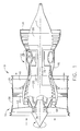
- Figure 1 is a schematic illustration of a gas turbine engine 10 having a longitudinal axis 11, and including a core gas turbine engine 12 and a fan section 14 positioned upstream of core engine 12.
- Core engine 12 includes a generally tubular outer casing 16 that defines an annular core engine inlet 18.
- Casing 16 surrounds a low-pressure booster 20 for raising the pressure of the incoming air to a first pressure level.
- engine 10 is a CFM56 engine available from General Electric Aircraft Engines, Cincinnati, Ohio.
- a high pressure, multi-stage, axial-flow compressor 22 receives pressurized air from booster 20 and further increases the pressure of the air to a second, higher pressure level.
- the high pressure air flows to a combustor 24 and is mixed with fuel.
- the fuel-air mixture is ignited to raise the temperature and energy level of the pressurized air.
- the high energy combustion products flow to a first turbine 26 for driving compressor 22 through a first drive shaft 28, and then to a second turbine 30 for driving booster 20 through a second drive shaft 32 that is coaxial with first drive shaft 28. After driving each of turbines 26 and 30, the combustion products leave core engine 12 through an exhaust nozzle 34 to provide propulsive jet thrust.
- Fan section 14 includes a rotatable, axial-flow fan rotor 36 that is driven by second turbine 30.
- An annular fan casing 38 surrounds fan rotor 36 and is supported from core engine 12 by a plurality of substantially radially-extending, circumferentially-spaced support struts 44.
- Fan rotor 36 carries a plurality of radially-extending, circumferentially spaced fan blades 42.
- Fan casing 38 extends rearwardly from fan rotor 36 over an outer portion of core engine 12 to define a secondary, or bypass airflow conduit.
- a casing element 39 that is downstream of and connected with fan casing 38 supports a plurality of fan stream outlet guide vanes 40. The air that passes through fan section 14 is propelled in a downstream direction by fan blades 42 to provide additional propulsive thrust to supplement the thrust provided by core engine 12.
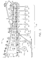
- FIG 2 is a cross-sectional view of a portion of a compressor 50 that may be used with core gas turbine 12 (shown in Figure 1).
- compressor 50 includes nine stages 45, wherein each stage 46 includes an array of radially-extending, circumferentially-spaced stator vanes 47 and a plurality of peripherally-carried, radially-extending, circumferentially-spaced rotor blades 48.
- Inlet guide vanes 51 and stator vanes 52 of stages one through three of compressor 50 are variable in that they are pivotable about an axis that extends radially relative to the compressor axis of rotation.
- Stator vanes 54 of stages four through eight and outlet guide vanes 55 are fixed in position.
- the respective rotor disks 56 include a series of peripherally-spaced, axially-extending dovetail slots 49 into which rotor blades 58 are inserted and from which rotor blades 58 are removed in an axial direction.
- Compressor 50 includes an inlet 66 that defines a flow passageway 67 having a relatively large flow area, and an outlet 68 that defines a relatively smaller area flow passageway 69 through which the compressed air passes.
- An outer boundary of the flow passageway is defined by an outer annular casing 70 and an inner boundary of the flow passageway is defined by the blade platforms of respective blades 58, 64 carried by rotors 56, 60, and also by a stationary annular seal ring 72 that is carried at an inner periphery of each of the respective stator sections 52, 54.
- respective rotor disks 56, 60 are ganged together by a suitable disk-to-disk coupling arrangement (not shown), and the third stage disk is connected with a drive shaft 74 that is operatively connected with a turbine rotor (not shown).
- Each stator section 52, 54 includes an annular abradable seal that is carried by a respective annular sealing ring 72 and that is adapted to be engaged by respective labyrinth seals carried by 56, 60 in order to minimize air leakage around the respective stators 52, 54.
- Sealing rings 72 also serve to confine the flow of air to the flow passageway defined by outer casing 70 and the radially innermost surfaces of the respective stator vanes 47.
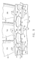
- FIG. 3 is an end view of a plurality of rotor blades 58 coupled to rotor disk 56.
- Rotor disk 56 includes a plate-like disk body 76 that terminates in an enlarged outer rim 78.
- Outer rim 78 includes a rotor-blade-receiving circumferential slot 84 that in the exemplary embodiment is substantially U-shaped.
- Slot 84 has a cross-sectional form of a dovetail, and includes a slot base 86.
- Slot 84 is defined by a forward sidewall 88 and an aft sidewall 90 that are spaced axially from each other and that extend in a generally radial direction.
- Each of forward and aft sidewalls 88, 90 has a respective inward convex projection 92, 94 that defines a generally dovetail-type shape of slot 84.
- Rotor blade 64 includes a base member 100 that has a shape that corresponds substantially with that of circumferential slot 84.
- Base member 100 as shown is in the form of a dovetail and includes an enlarged base portion 110 that is received in lateral recesses 112, 114 formed in rotor slot 84.
- Base member 100 also includes a recessed portion 116, 118 on each side to receive the inwardly-extending convex projections 92, 94 of rotor slot 84.
- a blade platform 120 is carried on base member 100 and extends in a generally transverse direction relative to the longitudinal axis of base member 100. Extending longitudinally from upper surface 119 of blade platform 120, and in a direction opposite to that of base member 100, is an airfoil portion 122, which is adapted to contact the gases that pass through engine 10.
- Figure 4 is an end view of plurality of rotor blades 58 coupled to rotor disk 56 shown in Figure 3.
- gas turbine engine 10 also includes a sealant 150 that is formed between at least one rotor blade 58 and rotor disk 56. More specifically, sealant 150 is deposited on a lower surface 160 of rotor blade 58 to facilitate sealing a gap 162 that is defined between blade lower surface 160 and dovetail slot 84. Although only a few rotor blades 58 are illustrated, it should be realized that in the exemplary embodiment, sealant 150 can be utilized to seal at least one gap 162 between a respect rotor blade 58 and disk 60.
- sealant 150 can be utilized to seal a plurality of gaps 162 defined between a plurality of rotor blades 58 and disk 60.
- sealant 150 can be utilized to seal a single blade 58 on a single disk 60, or a plurality of blades 58 on a single disk 60.
- sealant 150 can be utilized to seal a plurality of blades 58 coupled to a plurality of disks 60.
- sealant 150 is utilized on the first three high pressure compressor stages 170, 172, and 174 (shown in Figure 2) to facilitate sealing the gaps 162 defined between each rotor blade 58 and rotor disk 60.
- sealant 150 is deposited on blade lower surface 160. After a predetermined quantity of time sufficient to cure sealant 150 has elapsed, blade 58 is coupled to disk 60. According, sealant 150 substantially seals gap 162 such that airflow cannot be channeled through gap 162.
- sealant 150 is a room temperature vulcanizing silicone oxime sealant that is deposited onto at least a portion of the compressor blade 58.
- Oxime as used herein is defined as one in a class of chemical compounds with the general formula R1R2CNOH, where R1 is an organic side chain and R2 is either hydrogen, forming an aldoxime, or another organic group, forming a ketoxime, and can be formed by the action of hydroxylamine on aldehydes or ketones.
- sealant 150 is deposited onto at least a portion of blade 58 as a thixotropic paste.
- Thixotropic as used herein, is defined a gel-like substance that becomes a fluid when subjected to either stirring or shaking, and then returns to a semi-solid state upon standing. Accordingly, sealant 150 is applied to at least a portion of blade 58 in a semi-fluidic state. Sealant 150 is then allowed to cure or harden onto blade 58. After sealant 150 has substantially cured, blade 58 is coupled to disk 60.
- sealant 150 is a room temperature oxime-cure silicone sealant such as for example, Loctite TM 5920. Accordingly, sealant 150 is capable of sealing gap 162 and retaining its elastomeric properties up to temperatures of at least 600 degrees Fahrenheit.
- Described herein is an exemplary sealant that facilitates reducing and/or eliminating the airflow between a high pressure compressor rotor disk and a compressor rotor blade. More specifically, the sealant is applied to a plurality of compressor blades that are coupled to the first three stages of a gas turbine engine compressor assembly.
- the sealant described herein is a room temperature vulcanizing silicone oxime sealant that is configured to withstand temperatures to at least 600 degrees Fahrenheit.
- the sealant described herein facilitates improving gas turbine engine performance by preventing airflow leakage between the compressor blades and the compressor rotor disk.
- known materials used in such applications cannot withstand operating temperatures of greater than approximately 600 degrees Fahrenheit for an extended period of time.
- leakage occurs when the known sealants material degrades with time and temperature and effectively disappears, thus eliminating the airflow seal around the component.
- the sealant described herein is configured to withstand temperatures greater than 600 degrees Fahrenheit and thus increase engine performance over an extended period of time.
Landscapes
- Engineering & Computer Science (AREA)
- Mechanical Engineering (AREA)
- General Engineering & Computer Science (AREA)
- Structures Of Non-Positive Displacement Pumps (AREA)
- Turbine Rotor Nozzle Sealing (AREA)
Abstract
Description
- This invention relates generally to gas turbine engines, and more specifically to methods and apparatus for assembling gas turbine engine components.
- Accurate manufacturing of a component may be a significant factor in determining a fabricating time of the component. Specifically, when the component is a gas turbine engine blade, accurate manufacturing of the blade may be one of the most significant factors affecting an overall cost of fabrication of the gas turbine engine, as well as subsequent modifications, repairs, and inspections of the blade. For example, at least some known gas turbine engines include a compressor for compressing air which is mixed with a fuel and channeled to a combustor wherein the mixture is ignited within a combustion chamber for generating hot combustion gases. At least some known compressors include a rotor assembly that includes at least one row of circumferentially spaced rotor blades. Each rotor blade includes an airfoil that includes a pressure side, and a suction side connected together at leading and trailing edges. Each airfoil extends radially outward from a rotor blade platform. Each rotor blade also includes a dovetail that extends radially inward from a shank coupled to the platform. The dovetail is used to mount the rotor blade within the rotor assembly to a rotor disk or spool.
- During operation, a pressure differential is created between the compressor blade pressure side and the compressor blade suction side which may result in an undesirable leakage flow between the upstream and downstream portions of the rotor. One such possible leakage path may form at an interconnection between each rotor blade and the rotor disk, where a gap may be defined between a blade base member, usually a dovetail design, and a rotor disk groove in which the rotor blades are carried.
- Accordingly, at least one known gas turbine engine includes a silicone acetoxy sealant to facilitate sealing the blade base and the rotor disk. However, as engine performance requirements have increased, resulting in increased operating temperatures, however the known sealant may not withstand the increased operating temperatures for an extended period of time. As a consequence, the sealant degrades causing leakage to occur between the blade and the disk.
- In one aspect of the invention, a method for assembling a gas turbine engine compressor having a plurality of stages and a plurality of blades coupled to each respective stage is provided. The method includes depositing a silicone oxime sealant onto at least a portion of a compressor blade, and coupling the compressor blade to a compressor disk such that the silicone oxime sealant is between the compressor blade and the compressor disk.
- In another aspect of the invention, a gas turbine engine rotor assembly is provided. The gas turbine engine rotor assembly includes a rotor disk, a plurality of circumferentially-space rotor blades coupled to the rotor disk, and a silicone oxime sealant deposited onto at least a portion of the rotor blade such that the silicone oxime sealant is between the rotor blade and the disk.
- In a further aspect of the invention, a gas turbine engine is provided. The gas turbine engine includes a rotor disk, a plurality of circumferentially-space rotor blades coupled to the rotor disk, and a silicone oxime sealant deposited onto at least a portion of the rotor blade such that the silicone oxime sealant is between the rotor blade and the disk.
- The invention will now be described in greater detail, by way of example, with reference to the drawings, in which:-
- Figure 1 is a schematic illustration of a gas turbine engine;
- Figure 2 is a cross-sectional view of the compressor shown in Figure 1;
- Figure 3 is an end view of an exemplary gas turbine engine blade coupled to an exemplary disk; and
- Figure 4 is an end view of the exemplary gas turbine engine blade coupled to an exemplary disk shown in Figure 3 including an exemplary sealant.
- As used herein, the terms "manufacture" and "manufacturing" may include any manufacturing process. For example, manufacturing processes may include grinding, finishing, polishing, cutting, machining, inspecting, and/or casting. The above examples are intended as exemplary only, and thus are not intended to limit in any way the definition and/or meaning of the terms "manufacture" and "manufacturing". In addition, as used herein the term "component" may include any object to which a manufacturing process is applied. Furthermore, although the invention is described herein in association with a gas turbine engine, and more specifically for use with a compressor blade for a gas turbine engine, it should be understood that the present invention may be applicable to any component and/or any manufacturing process. Accordingly, practice of the present invention is not limited to the manufacture of compressor blades or other components of gas turbine engines.
- Figure 1 is a schematic illustration of a
gas turbine engine 10 having alongitudinal axis 11, and including a coregas turbine engine 12 and afan section 14 positioned upstream ofcore engine 12.Core engine 12 includes a generally tubularouter casing 16 that defines an annularcore engine inlet 18. Casing 16 surrounds a low-pressure booster 20 for raising the pressure of the incoming air to a first pressure level. In one embodiment,engine 10 is a CFM56 engine available from General Electric Aircraft Engines, Cincinnati, Ohio. - A high pressure, multi-stage, axial-
flow compressor 22 receives pressurized air frombooster 20 and further increases the pressure of the air to a second, higher pressure level. The high pressure air flows to acombustor 24 and is mixed with fuel. The fuel-air mixture is ignited to raise the temperature and energy level of the pressurized air. The high energy combustion products flow to afirst turbine 26 for drivingcompressor 22 through afirst drive shaft 28, and then to asecond turbine 30 for drivingbooster 20 through asecond drive shaft 32 that is coaxial withfirst drive shaft 28. After driving each ofturbines core engine 12 through anexhaust nozzle 34 to provide propulsive jet thrust. -
Fan section 14 includes a rotatable, axial-flow fan rotor 36 that is driven bysecond turbine 30. Anannular fan casing 38 surroundsfan rotor 36 and is supported fromcore engine 12 by a plurality of substantially radially-extending, circumferentially-spaced support struts 44.Fan rotor 36 carries a plurality of radially-extending, circumferentially spacedfan blades 42.Fan casing 38 extends rearwardly fromfan rotor 36 over an outer portion ofcore engine 12 to define a secondary, or bypass airflow conduit. Acasing element 39 that is downstream of and connected withfan casing 38 supports a plurality of fan streamoutlet guide vanes 40. The air that passes throughfan section 14 is propelled in a downstream direction byfan blades 42 to provide additional propulsive thrust to supplement the thrust provided bycore engine 12. - Figure 2 is a cross-sectional view of a portion of a
compressor 50 that may be used with core gas turbine 12 (shown in Figure 1). In the exemplary embodiment,compressor 50 includes ninestages 45, wherein eachstage 46 includes an array of radially-extending, circumferentially-spaced stator vanes 47 and a plurality of peripherally-carried, radially-extending, circumferentially-spacedrotor blades 48. Inlet guide vanes 51 andstator vanes 52 of stages one through three ofcompressor 50 are variable in that they are pivotable about an axis that extends radially relative to the compressor axis of rotation. Stator vanes 54 of stages four through eight andoutlet guide vanes 55 are fixed in position. Additionally, in stages one through three therespective rotor disks 56 include a series of peripherally-spaced, axially-extendingdovetail slots 49 into whichrotor blades 58 are inserted and from whichrotor blades 58 are removed in an axial direction.Rotor disks 60 for stages four through nine, on the other hand, each have a single, circumferentially-extendingdovetail slot 62, into whichrotor blades 64 are inserted in a generally tangential direction relative torotor disk 60. -
Compressor 50 includes aninlet 66 that defines aflow passageway 67 having a relatively large flow area, and anoutlet 68 that defines a relatively smallerarea flow passageway 69 through which the compressed air passes. An outer boundary of the flow passageway is defined by an outerannular casing 70 and an inner boundary of the flow passageway is defined by the blade platforms ofrespective blades rotors annular seal ring 72 that is carried at an inner periphery of each of therespective stator sections respective rotor disks drive shaft 74 that is operatively connected with a turbine rotor (not shown). - Each
stator section annular sealing ring 72 and that is adapted to be engaged by respective labyrinth seals carried by 56, 60 in order to minimize air leakage around therespective stators Sealing rings 72 also serve to confine the flow of air to the flow passageway defined byouter casing 70 and the radially innermost surfaces of therespective stator vanes 47. - Figure 3 is an end view of a plurality of
rotor blades 58 coupled torotor disk 56.Rotor disk 56 includes a plate-like disk body 76 that terminates in an enlargedouter rim 78.Outer rim 78 includes a rotor-blade-receivingcircumferential slot 84 that in the exemplary embodiment is substantially U-shaped.Slot 84 has a cross-sectional form of a dovetail, and includes aslot base 86.Slot 84 is defined by aforward sidewall 88 and anaft sidewall 90 that are spaced axially from each other and that extend in a generally radial direction. Each of forward andaft sidewalls convex projection slot 84. -
Rotor blade 64 includes abase member 100 that has a shape that corresponds substantially with that ofcircumferential slot 84.Base member 100 as shown is in the form of a dovetail and includes anenlarged base portion 110 that is received inlateral recesses rotor slot 84.Base member 100 also includes a recessedportion convex projections rotor slot 84. Ablade platform 120 is carried onbase member 100 and extends in a generally transverse direction relative to the longitudinal axis ofbase member 100. Extending longitudinally fromupper surface 119 ofblade platform 120, and in a direction opposite to that ofbase member 100, is anairfoil portion 122, which is adapted to contact the gases that pass throughengine 10. - Figure 4 is an end view of plurality of
rotor blades 58 coupled torotor disk 56 shown in Figure 3. In the exemplary embodiment,gas turbine engine 10 also includes asealant 150 that is formed between at least onerotor blade 58 androtor disk 56. More specifically,sealant 150 is deposited on alower surface 160 ofrotor blade 58 to facilitate sealing agap 162 that is defined between bladelower surface 160 anddovetail slot 84. Although only afew rotor blades 58 are illustrated, it should be realized that in the exemplary embodiment,sealant 150 can be utilized to seal at least onegap 162 between arespect rotor blade 58 anddisk 60. Alternatively,sealant 150 can be utilized to seal a plurality ofgaps 162 defined between a plurality ofrotor blades 58 anddisk 60. Specifically,sealant 150 can be utilized to seal asingle blade 58 on asingle disk 60, or a plurality ofblades 58 on asingle disk 60. Moreover,sealant 150 can be utilized to seal a plurality ofblades 58 coupled to a plurality ofdisks 60. In the exemplary embodiment,sealant 150 is utilized on the first three high pressure compressor stages 170, 172, and 174 (shown in Figure 2) to facilitate sealing thegaps 162 defined between eachrotor blade 58 androtor disk 60. - In the exemplary embodiment,
sealant 150 is deposited on bladelower surface 160. After a predetermined quantity of time sufficient to curesealant 150 has elapsed,blade 58 is coupled todisk 60. According,sealant 150 substantially sealsgap 162 such that airflow cannot be channeled throughgap 162. - In the exemplary embodiment,
sealant 150 is a room temperature vulcanizing silicone oxime sealant that is deposited onto at least a portion of thecompressor blade 58. Oxime as used herein is defined as one in a class of chemical compounds with the general formula R1R2CNOH, where R1 is an organic side chain and R2 is either hydrogen, forming an aldoxime, or another organic group, forming a ketoxime, and can be formed by the action of hydroxylamine on aldehydes or ketones. - Moreover, during use,
sealant 150 is deposited onto at least a portion ofblade 58 as a thixotropic paste. Thixotropic as used herein, is defined a gel-like substance that becomes a fluid when subjected to either stirring or shaking, and then returns to a semi-solid state upon standing. Accordingly,sealant 150 is applied to at least a portion ofblade 58 in a semi-fluidic state.Sealant 150 is then allowed to cure or harden ontoblade 58. Aftersealant 150 has substantially cured,blade 58 is coupled todisk 60. In the exemplary embodiment,sealant 150 is a room temperature oxime-cure silicone sealant such as for example, Loctite™ 5920. Accordingly,sealant 150 is capable of sealinggap 162 and retaining its elastomeric properties up to temperatures of at least 600 degrees Fahrenheit. - Described herein is an exemplary sealant that facilitates reducing and/or eliminating the airflow between a high pressure compressor rotor disk and a compressor rotor blade. More specifically, the sealant is applied to a plurality of compressor blades that are coupled to the first three stages of a gas turbine engine compressor assembly. The sealant described herein is a room temperature vulcanizing silicone oxime sealant that is configured to withstand temperatures to at least 600 degrees Fahrenheit.
- More specifically, the sealant described herein facilitates improving gas turbine engine performance by preventing airflow leakage between the compressor blades and the compressor rotor disk. For example, known materials used in such applications cannot withstand operating temperatures of greater than approximately 600 degrees Fahrenheit for an extended period of time. As a consequence, leakage occurs when the known sealants material degrades with time and temperature and effectively disappears, thus eliminating the airflow seal around the component. Whereas the sealant described herein is configured to withstand temperatures greater than 600 degrees Fahrenheit and thus increase engine performance over an extended period of time.
Claims (10)
- A gas turbine engine rotor assembly (10) comprising:a rotor disk (56);a plurality of circumferentially-space rotor blades (58) coupled to said rotor disk; anda silicone oxime sealant (150) deposited onto at least a portion of said rotor blade or said rotor disk such that said silicone oxime sealant is between said rotor blade and said disk.
- A gas turbine engine rotor assembly (10) in accordance with Claim 1 wherein said rotor disk (56) comprises a compressor rotor disk, and said rotor blades (58, 64) comprise compressor rotor blades.
- A gas turbine engine rotor assembly (10) in accordance with Claim 1 wherein said silicone oxime sealant (150) comprises a room temperature vulcanizing silicone oxime sealant.
- A gas turbine engine rotor assembly (10) in accordance with Claim 1 wherein said rotor disk (56) comprises at least one of a first stage (170) compressor rotor disk, a second stage (172) compressor rotor disk, and a third stage (174) compressor rotor disk.
- A gas turbine engine rotor assembly (10) in accordance with Claim 1 wherein said silicone oxime sealant (150) is operable at a temperature greater than 600 degrees Fahrenheit.
- A gas turbine engine rotor assembly (10) in accordance with Claim 1 wherein said rotor blade (58) comprises a dovetail, said turbine rotor disk (60) comprises a dovetail slot (62), said silicone oxime sealant(150) deposited between said dovetail and said dovetail slot.
- A gas turbine engine (12) comprising:a rotor disk (56);a plurality of rotor blades (58) coupled to said rotor disk; anda silicone oxime sealant (150) deposited onto at least a portion of at least one of said rotor blades or said rotor disk such that said silicone oxime sealant is between said rotor blade and said disk.
- A gas turbine engine (12) in accordance with Claim 7 wherein said rotor disk (56) comprises a compressor rotor disk (58), and said rotor blades comprise compressor rotor blades.
- A gas turbine engine (12) in accordance with Claim 7 wherein said silicone oxime sealant (150) comprises a room temperature vulcanizing silicone oxime sealant.
- A gas turbine engine (12) in accordance with Claim 7 wherein said rotor disk (56) comprises at least one of a first stage (170) compressor rotor disk, a second stage (172) compressor rotor disk, and a third stage (174) compressor rotor disk.
Applications Claiming Priority (1)
| Application Number | Priority Date | Filing Date | Title |
|---|---|---|---|
| US11/210,520 US20070048140A1 (en) | 2005-08-24 | 2005-08-24 | Methods and apparatus for assembling gas turbine engines |
Publications (2)
| Publication Number | Publication Date |
|---|---|
| EP1757774A2 true EP1757774A2 (en) | 2007-02-28 |
| EP1757774A3 EP1757774A3 (en) | 2008-07-23 |
Family
ID=37067649
Family Applications (1)
| Application Number | Title | Priority Date | Filing Date |
|---|---|---|---|
| EP06254334A Withdrawn EP1757774A3 (en) | 2005-08-24 | 2006-08-17 | Gas turbine rotor blade assembly and corresponding gas turbine |
Country Status (4)
| Country | Link |
|---|---|
| US (1) | US20070048140A1 (en) |
| EP (1) | EP1757774A3 (en) |
| JP (1) | JP2007056874A (en) |
| CN (1) | CN1920311B (en) |
Cited By (3)
| Publication number | Priority date | Publication date | Assignee | Title |
|---|---|---|---|---|
| GB2452515A (en) * | 2007-09-06 | 2009-03-11 | Siemens Ag | Seal coating for rotor blade and/or disc slot |
| WO2014100203A1 (en) * | 2012-12-18 | 2014-06-26 | United Technologies Corporation | Root spacer for arranging between a rotor disk and a root of a rotor blade |
| WO2015047449A1 (en) | 2013-09-30 | 2015-04-02 | United Technologies Corporation | Compressor area splits for geared turbofan |
Families Citing this family (13)
| Publication number | Priority date | Publication date | Assignee | Title |
|---|---|---|---|---|
| GB0705696D0 (en) * | 2007-03-24 | 2007-05-02 | Rolls Royce Plc | A method of repairing a damaged abradable coating |
| US20090229194A1 (en) * | 2008-03-11 | 2009-09-17 | Advanced Shielding Technologies Europe S.I. | Portable modular data center |
| FR2933884B1 (en) * | 2008-07-16 | 2012-07-27 | Snecma | PROCESS FOR MANUFACTURING AN AUBING PIECE |
| US20100068062A1 (en) * | 2008-09-12 | 2010-03-18 | General Electric Company | Turbine bucket with dovetail seal and related method |
| US8678754B2 (en) | 2011-01-24 | 2014-03-25 | General Electric Company | Assembly for preventing fluid flow |
| US9982549B2 (en) | 2012-12-18 | 2018-05-29 | United Technologies Corporation | Turbine under platform air seal strip |
| US9359906B2 (en) | 2012-12-18 | 2016-06-07 | United Technologies Corporation | Rotor blade root spacer with a fracture feature |
| FR3008639B1 (en) * | 2013-07-18 | 2015-08-07 | Snecma | METHOD FOR ASSEMBLING TURBOMACHINE PARTS AND ASSEMBLY IMPLEMENTED THEREIN |
| CN105003461A (en) * | 2015-06-29 | 2015-10-28 | 肖彦均 | Sealing structure of fan impeller blades for dust collector |
| US10125619B2 (en) * | 2015-11-19 | 2018-11-13 | General Electric Company | Rotor assembly for use in a turbofan engine and method of assembling |
| KR101882099B1 (en) | 2016-11-10 | 2018-07-25 | 두산중공업 주식회사 | Structure for cooling turbine's rotor part |
| KR102181400B1 (en) * | 2019-03-25 | 2020-11-23 | 두산중공업 주식회사 | Jig for testing blade |
| CN113833696A (en) * | 2021-10-26 | 2021-12-24 | 中国航发贵州黎阳航空动力有限公司 | A kind of installation method for the third stage rotor assembly blade of high pressure compressor |
Citations (1)
| Publication number | Priority date | Publication date | Assignee | Title |
|---|---|---|---|---|
| US20020162648A1 (en) * | 2001-05-02 | 2002-11-07 | Transpro, Inc. | Resiliently bonded heat exchanger |
Family Cites Families (15)
| Publication number | Priority date | Publication date | Assignee | Title |
|---|---|---|---|---|
| DE2658345A1 (en) * | 1976-12-23 | 1978-06-29 | Motoren Turbinen Union | Gas turbine impeller for turbine or compressor part - has sealing pieces between blade roots to prevent leakage recirculation |
| US4580946A (en) * | 1984-11-26 | 1986-04-08 | General Electric Company | Fan blade platform seal |
| US4847396A (en) * | 1985-04-04 | 1989-07-11 | Loctite Corporation | Auto-adhering one-component RTV silicone sealant composition utilizing an adhesion promoter |
| US4790723A (en) * | 1987-01-12 | 1988-12-13 | Westinghouse Electric Corp. | Process for securing a turbine blade |
| US5139389A (en) * | 1990-09-14 | 1992-08-18 | United Technologies Corporation | Expandable blade root sealant |
| GB9209895D0 (en) * | 1992-05-07 | 1992-06-24 | Rolls Royce Plc | Rotors for gas turbine engines |
| JP3401928B2 (en) * | 1994-08-11 | 2003-04-28 | 石川島播磨重工業株式会社 | Buffer material for turbine blade implant |
| FR2726323B1 (en) * | 1994-10-26 | 1996-12-13 | Snecma | ASSEMBLY OF A ROTARY DISC AND BLADES, ESPECIALLY USED IN A TURBOMACHINE |
| US5873702A (en) * | 1997-06-20 | 1999-02-23 | Siemens Westinghouse Power Corporation | Apparatus and method for sealing gas turbine blade roots |
| EP1097325B1 (en) * | 1998-07-15 | 2004-02-04 | Siemens Aktiengesellschaft | Sealing system, especially for a rotary machine |
| JP2000045705A (en) * | 1998-07-31 | 2000-02-15 | Hitachi Ltd | gas turbine |
| DE19848103A1 (en) * | 1998-10-19 | 2000-04-20 | Asea Brown Boveri | Sealing arrangement |
| GB9915637D0 (en) * | 1999-07-06 | 1999-09-01 | Rolls Royce Plc | A rotor seal |
| US7059821B2 (en) * | 2003-05-07 | 2006-06-13 | General Electric Company | Method and apparatus to facilitate sealing within turbines |
| JP4352757B2 (en) * | 2003-05-14 | 2009-10-28 | 株式会社Ihi | Jet engine fan and fan spacer |
-
2005
- 2005-08-24 US US11/210,520 patent/US20070048140A1/en not_active Abandoned
-
2006
- 2006-08-17 EP EP06254334A patent/EP1757774A3/en not_active Withdrawn
- 2006-08-23 JP JP2006225954A patent/JP2007056874A/en active Pending
- 2006-08-24 CN CN2006101262083A patent/CN1920311B/en not_active Expired - Fee Related
Patent Citations (1)
| Publication number | Priority date | Publication date | Assignee | Title |
|---|---|---|---|---|
| US20020162648A1 (en) * | 2001-05-02 | 2002-11-07 | Transpro, Inc. | Resiliently bonded heat exchanger |
Cited By (7)
| Publication number | Priority date | Publication date | Assignee | Title |
|---|---|---|---|---|
| GB2452515A (en) * | 2007-09-06 | 2009-03-11 | Siemens Ag | Seal coating for rotor blade and/or disc slot |
| GB2452515B (en) * | 2007-09-06 | 2009-08-05 | Siemens Ag | Seal coating between rotor blade and rotor disk slot in gas turbine engine |
| WO2009030606A3 (en) * | 2007-09-06 | 2009-11-12 | Siemens Aktiengesellschaft | Seal coating between rotor blade and rotor disk slot in gas turbine engine |
| US8545183B2 (en) | 2007-09-06 | 2013-10-01 | Siemens Aktiengesellschaft | Seal coating between rotor blade and rotor disk slot in gas turbine engine |
| WO2014100203A1 (en) * | 2012-12-18 | 2014-06-26 | United Technologies Corporation | Root spacer for arranging between a rotor disk and a root of a rotor blade |
| WO2015047449A1 (en) | 2013-09-30 | 2015-04-02 | United Technologies Corporation | Compressor area splits for geared turbofan |
| EP3052812A4 (en) * | 2013-09-30 | 2016-10-05 | United Technologies Corp | COMPRESSOR ZONE DIVISIONS FOR FORMING A REDUCING TURBOSOUFFLANTE |
Also Published As
| Publication number | Publication date |
|---|---|
| CN1920311A (en) | 2007-02-28 |
| EP1757774A3 (en) | 2008-07-23 |
| CN1920311B (en) | 2010-05-26 |
| US20070048140A1 (en) | 2007-03-01 |
| JP2007056874A (en) | 2007-03-08 |
Similar Documents
| Publication | Publication Date | Title |
|---|---|---|
| US8016565B2 (en) | Methods and apparatus for assembling gas turbine engines | |
| US7334331B2 (en) | Methods and apparatus for machining components | |
| US6375429B1 (en) | Turbomachine blade-to-rotor sealing arrangement | |
| EP2369138B1 (en) | Gas turbine engine with non-axisymmetric surface contoured vane platform | |
| EP2474708B1 (en) | Air seal assembly and corresponding assembly method | |
| EP1757774A2 (en) | Gas turbine rotor blade assembly and corresponding gas turbine | |
| CN109416050B (en) | Axial compressor with splitter blades | |
| EP0615055A1 (en) | A stator blade cooling | |
| EP3205825A1 (en) | Centrifugal compressor assembly for use in a turbine engine and method of assembly | |
| EP3540180A1 (en) | Inter-stage cavity purge ducts | |
| US20160186590A1 (en) | Cover plate assembly for a gas turbine engine | |
| CN109477391B (en) | Turbofan engine and corresponding method of operation | |
| CA2958106A1 (en) | Turbine engine shroud assembly | |
| CN114718656A (en) | System for controlling blade clearance within a gas turbine engine | |
| US6848885B1 (en) | Methods and apparatus for fabricating gas turbine engines | |
| CN113167125A (en) | Sealing between a rotor disk and a stator of a turbomachine | |
| CN110242617B (en) | Compressor rotor cooling equipment | |
| EP2995778A1 (en) | Method and assembly for reducing secondary heat in a gas turbine engine | |
| EP3425164B1 (en) | Tandem rotor disk apparatus and corresponding gas turbine engine | |
| EP3290637B1 (en) | Tandem rotor blades with cooling features | |
| US12286885B1 (en) | Turbine assembly with confronting vane and turbine shroud segment | |
| US12281576B2 (en) | Turbomachine distributor comprising a gas reintroduction duct with a tangential component | |
| CN112585334B (en) | Rotor discs with axially fixed blades, assemblies of discs and rings, and turbines | |
| CN120720242A (en) | Compact core arrangement for high bypass ratio gas turbine engine architecture | |
| CN114251132A (en) | Gas turbine engine rotor blade with metallic structural member and composite fairing |
Legal Events
| Date | Code | Title | Description |
|---|---|---|---|
| PUAI | Public reference made under article 153(3) epc to a published international application that has entered the european phase |
Free format text: ORIGINAL CODE: 0009012 |
|
| AK | Designated contracting states |
Kind code of ref document: A2 Designated state(s): AT BE BG CH CY CZ DE DK EE ES FI FR GB GR HU IE IS IT LI LT LU LV MC NL PL PT RO SE SI SK TR |
|
| AX | Request for extension of the european patent |
Extension state: AL BA HR MK YU |
|
| PUAL | Search report despatched |
Free format text: ORIGINAL CODE: 0009013 |
|
| AK | Designated contracting states |
Kind code of ref document: A3 Designated state(s): AT BE BG CH CY CZ DE DK EE ES FI FR GB GR HU IE IS IT LI LT LU LV MC NL PL PT RO SE SI SK TR |
|
| AX | Request for extension of the european patent |
Extension state: AL BA HR MK RS |
|
| 17P | Request for examination filed |
Effective date: 20090123 |
|
| 17Q | First examination report despatched |
Effective date: 20090225 |
|
| AKX | Designation fees paid |
Designated state(s): DE FR GB |
|
| STAA | Information on the status of an ep patent application or granted ep patent |
Free format text: STATUS: THE APPLICATION IS DEEMED TO BE WITHDRAWN |
|
| 18D | Application deemed to be withdrawn |
Effective date: 20110223 |