EP1757769B1 - Schlagbohrneissel - Google Patents
Schlagbohrneissel Download PDFInfo
- Publication number
- EP1757769B1 EP1757769B1 EP06017693A EP06017693A EP1757769B1 EP 1757769 B1 EP1757769 B1 EP 1757769B1 EP 06017693 A EP06017693 A EP 06017693A EP 06017693 A EP06017693 A EP 06017693A EP 1757769 B1 EP1757769 B1 EP 1757769B1
- Authority
- EP
- European Patent Office
- Prior art keywords
- chuck
- drill bit
- drill
- wear sleeve
- bit
- Prior art date
- Legal status (The legal status is an assumption and is not a legal conclusion. Google has not performed a legal analysis and makes no representation as to the accuracy of the status listed.)
- Not-in-force
Links
Images


Classifications
-
- E—FIXED CONSTRUCTIONS
- E21—EARTH OR ROCK DRILLING; MINING
- E21B—EARTH OR ROCK DRILLING; OBTAINING OIL, GAS, WATER, SOLUBLE OR MELTABLE MATERIALS OR A SLURRY OF MINERALS FROM WELLS
- E21B10/00—Drill bits
- E21B10/36—Percussion drill bits
-
- E—FIXED CONSTRUCTIONS
- E21—EARTH OR ROCK DRILLING; MINING
- E21B—EARTH OR ROCK DRILLING; OBTAINING OIL, GAS, WATER, SOLUBLE OR MELTABLE MATERIALS OR A SLURRY OF MINERALS FROM WELLS
- E21B17/00—Drilling rods or pipes; Flexible drill strings; Kellies; Drill collars; Sucker rods; Cables; Casings; Tubings
- E21B17/02—Couplings; joints
- E21B17/04—Couplings; joints between rod or the like and bit or between rod and rod or the like
- E21B17/07—Telescoping joints for varying drill string lengths; Shock absorbers
- E21B17/076—Telescoping joints for varying drill string lengths; Shock absorbers between rod or pipe and drill bit
Definitions
- the invention relates to a drill bit for a down-the-hole drill hammer.
- Drill bits of this kind conventionally have a shank which fits inside the drill housing and an exposed head at the forward end, for example as shown in EP1462604A2 .
- the head is provided with teeth on a drilling face at its working end.
- the shank has splines which are engaged by corresponding splines in a chuck secured in the drill hammer.
- the rear end of the bit shank forms a striking face onto which a reciprocating piston hammer impacts during operation.
- a section of reduced diameter Between the striking face and the splines, is a section of reduced diameter. This section defines a pair of shoulders between which a retaining ring, normally above the chuck, slidably engages the bit.
- the section of reduced diameter has to be longer than the axial thickness of the retaining ring. This allows for the necessary axial or longitudinal movement of the bit.
- the drill hammers operate with different air flow paths which sometimes require the bit to include a foot valve tube. There is however a tendency towards drill hammers with bits that do not require these tubes.
- US6263988 discloses a downhole drilled system including a primary drive shaft with a drill head coupled thereto via a drill head de-coupling assembly.
- WO91/10805 discloses a drilling tool comprising a bit, a reamer and a guide body.
- a drill is connected to be rotated within a casing tube by a drill string in unison with the guide body.
- DE9308443 discloses a drill bit comprising a head, a guidance shank fitted within a drilling shoe and a driver shank having a driver wing which engages a slot in a drill pipe.
- an assembly for use with a down-the-hole drill hammer having a reciprocating piston comprising a wear sleeve, a drill bit and an annular reciprocating chuck, the drill bit comprising a head with a shank adapted to be releasably secured in the chuck, the chuck being adapted to slidably receive the forward end of the piston, a limited sliding fit being provided between the chuck and the wear sleeve and retaining means being provided for retaining the chuck within the wear sleeve
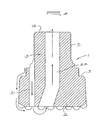
- a drill bit (1) having a head (2) at its forward end. Extending from the head (2) is a shank (3) which is adapted to be releasably secured in a reciprocating chuck (4).
- the shank (3) has screw threads (5) along its length.
- the chuck (4) is provided as a sleeve, with corresponding screw threads (6) along its inside adjacent its forward end.
- An outwardly or laterally extending shoulder (7) is provided at the rear end of the chuck (4).
- the exterior of the chuck (4) from the shoulder (7) to its forward end is splined with the shoulder (7) formed between the splines (8).
- the splines (8) of the chuck (4) engage in corresponding splines (9) in the wear sleeve or housing (10) of a drill hammer.
- the rear end of each of the splines (9) provides a shoulder (11) to retain the chuck (4) in the wear sleeve (10).
- the chuck (4) When the drill hammer is assembled, the chuck (4) is inserted from the rear of the wear sleeve (10). The chuck (4) slides forward and once the splines (8) and (9) mesh, the shoulder (7) of the chuck (4) will abut the shoulders (11) in the wear sleeve (10). The remainder of the drill hammer components are then fitted to complete the assembly.
- the drill bit (1) can then be fitted by screwing it into fixed engagement with the chuck (4).
- the chuck (4) is thus secured around the shank (3) which provides, at its rear end, a striking face (12) for the bit (1).
- the shoulders (7) and (11) limit the forward stroke of the bit (1) when the striking face (12) at its rear end is impacted by the piston hammer (not shown).
- the shoulder (13) provided around the rear of the head (2) will stop against the forward end (14) of the wear sleeve (10) when the bit (1) is lifted.
- This embodiment of the drill bit (1) has a foot valve tube (15) and axial exhaust passage (16) which opens through the drilling face of the head (2).
- Two further embodiments of the drill bit (1), which do not have such a tube, are shown in Figures 2 and 3 respectively. The same reference numerals from Figure 1 are used for corresponding components in the other two figures.
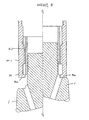
- the drill bit (1) of Figure 2 is provided in a drill hammer (17) based on the disclosures of my South African Patent Number 2004/2256 . That specification sets out the airflow paths of the operation cycle in some detail. That detail will not be repeated here.
- the bit (1) and chuck (4) are shown in a lifted or rearward position, with the shoulder (13) on the head (2) against the forward end (14) of the wear sleeve (10).
- the piston (18) reciprocates under influence of pressurized air which comes down the control rod or air distributor (19).
- the forward end of the piston (18) is slidably received in the annular chuck (4) provided around the striking face (12).
- the chuck (4) thus operates as a piston stem bush from which the forward portion of the piston (18) is lifted to exhaust the lower chamber.
- FIG 3 another bit (1) is provided to operate with an embodiment of the drill hammer in Figure 2 wherein the exhaust takes place through the centre of the bit (1), via passage (20).
- a chuck suitable for a particular drill hammer of this type will be within the design competence of a person skilled in the art.
- Figure 4 shows another embodiment of a drill bit (1) in accordance with this invention but for use with a reverse circulation drill hammer (not shown).
- the exhaust air travels around the outside of the head (2) and through passage (21) to the bottom of the hole.
- the drilled cuttings are then entrained in the flow of air upwardly through bore (22).
- the bore (22) communicates with through the drill hammer to a passage extending through the centre of dual rods (not shown) to the surface.
- This flow of exhaust air is indicated by the arrows in Figure 4 .
- a suitable chuck will be within the design competence of a person skilled in the art.
- the chuck (4.1) need not have an outwardly extending shoulder as illustrated in Figure 1 .
- the chuck (4.1) illustrated in Figure 5 is splined thoughout its entire length.
- the wear sleeve (10.1) has an inward lip (30) formed at its rear end (31) to retain the chuck (4.1) thereinside.
- the invention provides a bit which can be used on most, if not all, types of down the hole drill hammers and which is simpler to machine. Screw threads replace the usual splines and other structural features ordinarily required. These are then provided in the more expensive parts of a drill hammer, namely the reciprocating chuck and wear sleeve.
- the conventional retaining ring is also not required in the embodiments shown.
Landscapes
- Engineering & Computer Science (AREA)
- Life Sciences & Earth Sciences (AREA)
- Geology (AREA)
- Mining & Mineral Resources (AREA)
- Mechanical Engineering (AREA)
- Physics & Mathematics (AREA)
- Environmental & Geological Engineering (AREA)
- Fluid Mechanics (AREA)
- General Life Sciences & Earth Sciences (AREA)
- Geochemistry & Mineralogy (AREA)
- Earth Drilling (AREA)
- Percussive Tools And Related Accessories (AREA)
Claims (5)
- Baugruppe (2, 4) zur Verwendung mit einem Bohrloch-Bohrhammer mit einem Hubkolben (18), wobei die Baugruppe eine Verschlelßhülse (10), einen Bohrer (1) und ein ringförmiges Schlagspannfutter (4) umfasst, wobei der Bohrer (1) einen Kopf (2) mit einem Schaft (3) umfasst, der adaptiert ist, lösbar im Spannfutter (4) gesichert zu werden, wobei das Spannfutter (4) adaptiert ist, das vordere Ende des Kolbens (18) gleitbar aufzunehmen, wobei eine begrenzte Gleitpassung zwischen dem Spannfutter und der Verschlelßhülse (10) vorgesehen ist und Haltemittel (7) vorgesehen sind, um das Spannfutter (4) innerhalb der Verschlelßhülse (10) festzuhalten.
- Bohrerbaugruppe nach Anspruch 1, dadurch gekennzeichnet, dass das Spannfutter (4) als eine Kolbenstangenbuchse für den Hammerkolben (18) fungiert
- Bohrerbaugruppe nach Anspruch 1 oder Anspruch 2, dadurch gekennzeichnet, dass der Schaft (3) entlang seiner Länge mit Gewinde (5) versehen ist und in ein entsprechendes Gewinde (6) im Spannfutter (4) eingreift.
- Bohrerbaugruppe nach einem beliebigen der Ansprüche 1 bis 3, dadurch gekennzeichnet, dass das Spannfutter (4) extern längsgenutet (8) ist, wobei die Längsnuten (8) des Spannfutters in entsprechende Längsnuten (9) in der Verschleißhülse (10) eingreifen.
- Bohrerbaugruppe nach Anspruch 4, dadurch gekennzeichnet, dass eine sich nach außen oder quer erstreckende Schulter (7) am hinteren Ende des Spannfutters (4) vorgesehen ist, um das Spannfutter innerhalb der Hülse (10) festzuhalten,
Applications Claiming Priority (1)
| Application Number | Priority Date | Filing Date | Title |
|---|---|---|---|
| ZA200506810 | 2005-08-25 |
Publications (2)
| Publication Number | Publication Date |
|---|---|
| EP1757769A1 EP1757769A1 (de) | 2007-02-28 |
| EP1757769B1 true EP1757769B1 (de) | 2012-11-14 |
Family
ID=37461534
Family Applications (1)
| Application Number | Title | Priority Date | Filing Date |
|---|---|---|---|
| EP06017693A Not-in-force EP1757769B1 (de) | 2005-08-25 | 2006-08-25 | Schlagbohrneissel |
Country Status (5)
| Country | Link |
|---|---|
| US (3) | US7712554B2 (de) |
| EP (1) | EP1757769B1 (de) |
| AU (1) | AU2006203706B2 (de) |
| CA (1) | CA2556795C (de) |
| ZA (1) | ZA200606939B (de) |
Cited By (2)
| Publication number | Priority date | Publication date | Assignee | Title |
|---|---|---|---|---|
| CN105934557A (zh) * | 2014-01-21 | 2016-09-07 | 山特维克知识产权股份有限公司 | 快速释放潜孔锤钻头组件 |
| RU2761069C2 (ru) * | 2017-07-20 | 2021-12-03 | Минкон Интернэшнл Лимитед | Буровое долото со съемной головной частью |
Families Citing this family (11)
| Publication number | Priority date | Publication date | Assignee | Title |
|---|---|---|---|---|
| AU2007312961B2 (en) * | 2006-10-20 | 2015-05-28 | Drillroc Pneumatic Pty Ltd | Down-the-hole hammer drill |
| US9068399B2 (en) | 2006-10-20 | 2015-06-30 | Drillroc Pneumatic Pty Ltd | Down-the-hole hammer drill |
| US20080099218A1 (en) * | 2006-10-26 | 2008-05-01 | Sandvik Intellectual Property Ab | Air actuated down-the-hole hammer for rock drilling, a drill bit and a foot valve to be used in the down-the-hole hammer |
| US7883154B2 (en) * | 2008-08-28 | 2011-02-08 | Kennametal Inc. | Cutting tool with water injection to the cutting bit shank |
| CA2807341A1 (en) * | 2009-08-05 | 2011-02-10 | Bernard Lionel Gien | Bit assembly for a down-the-hole hammer drill |
| IES20100666A2 (en) * | 2010-10-15 | 2011-06-22 | Minroc Techn Promotions Ltd | A down-the-hole hammer |
| WO2012056434A1 (en) * | 2010-10-28 | 2012-05-03 | Gien Bernard L | A down-the-hole hammer drill assembly |
| AU2021246814A1 (en) | 2020-03-30 | 2022-11-10 | Mincon International Limited | Flushing and connection arrangements for percussion drill tools |
| EP3913184B1 (de) * | 2020-05-19 | 2023-07-12 | Sandvik Mining and Construction Tools AB | Keilschmierung für dth-hämmer |
| FI130902B1 (en) | 2020-07-03 | 2024-05-21 | Robit Plc | A drill assembly for percussive drilling |
| CN117365304B (zh) * | 2023-12-06 | 2024-02-27 | 山西省地球物理化学勘查院有限公司 | 一种地质勘探用钻头 |
Citations (1)
| Publication number | Priority date | Publication date | Assignee | Title |
|---|---|---|---|---|
| EP1462604A2 (de) * | 2003-03-25 | 2004-09-29 | Bernard Lionel Gien | Bohrwerkzeug im Bohrloch |
Family Cites Families (15)
| Publication number | Priority date | Publication date | Assignee | Title |
|---|---|---|---|---|
| US2661928A (en) * | 1952-02-09 | 1953-12-08 | Gulf Research Development Co | Hammer drill |
| US2947519A (en) * | 1957-09-11 | 1960-08-02 | Westinghouse Air Brake Co | Percussion drill |
| US2947517A (en) * | 1958-06-23 | 1960-08-02 | Charles W Simonsen | Motor winch |
| US3065805A (en) * | 1958-12-15 | 1962-11-27 | Leo A Martini | Apparatus for drilling wells |
| US3379261A (en) * | 1966-05-23 | 1968-04-23 | Leo A. Martini | Percussion tool |
| US3735820A (en) * | 1971-05-05 | 1973-05-29 | Baker Oil Tools Inc | Bore hole air hammer |
| CA2074076A1 (en) | 1990-01-17 | 1991-07-18 | Karl-Axel Stjernstrom | Drilling tool for percussive and rotary drilling |
| SE506207C2 (sv) * | 1992-01-22 | 1997-11-24 | Sandvik Ab | Sänkborrmaskin |
| DE9308443U1 (de) | 1993-06-05 | 1993-08-19 | Bilfinger + Berger Bauaktiengesellschaft, 68165 Mannheim | Vollbohrkrone zum Herstellen von verrohrten Erdbohrungen |
| US5647447A (en) * | 1996-06-10 | 1997-07-15 | Ingersoll-Rand Company | Bit retention device for a bit and chuck assembly of a down-the-hole percussive drill |
| US6263988B1 (en) | 1998-10-19 | 2001-07-24 | Jacob Matatof | Downhole drill system and de-coupling assembly |
| US6338390B1 (en) * | 1999-01-12 | 2002-01-15 | Baker Hughes Incorporated | Method and apparatus for drilling a subterranean formation employing drill bit oscillation |
| US6698537B2 (en) * | 2001-12-05 | 2004-03-02 | Numa Tool Company | Bit retention system |
| US7117939B1 (en) * | 2002-11-20 | 2006-10-10 | Gregory Dee Hawley | Percussion hammer bit retainer apparatus |
| AU2003903831A0 (en) * | 2003-07-24 | 2003-08-07 | Sparr Drilling Equipment Pty Ltd | Downhole hammer drill |
-
2006
- 2006-08-21 ZA ZA200606939A patent/ZA200606939B/xx unknown
- 2006-08-22 US US11/466,187 patent/US7712554B2/en active Active
- 2006-08-23 CA CA2556795A patent/CA2556795C/en not_active Expired - Fee Related
- 2006-08-25 AU AU2006203706A patent/AU2006203706B2/en not_active Ceased
- 2006-08-25 EP EP06017693A patent/EP1757769B1/de not_active Not-in-force
-
2010
- 2010-05-10 US US12/776,589 patent/US20100236832A1/en not_active Abandoned
-
2013
- 2013-04-01 US US13/854,250 patent/US20130327576A1/en not_active Abandoned
Patent Citations (1)
| Publication number | Priority date | Publication date | Assignee | Title |
|---|---|---|---|---|
| EP1462604A2 (de) * | 2003-03-25 | 2004-09-29 | Bernard Lionel Gien | Bohrwerkzeug im Bohrloch |
Cited By (3)
| Publication number | Priority date | Publication date | Assignee | Title |
|---|---|---|---|---|
| CN105934557A (zh) * | 2014-01-21 | 2016-09-07 | 山特维克知识产权股份有限公司 | 快速释放潜孔锤钻头组件 |
| CN105934557B (zh) * | 2014-01-21 | 2019-08-06 | 山特维克知识产权股份有限公司 | 快速释放潜孔锤钻头组件 |
| RU2761069C2 (ru) * | 2017-07-20 | 2021-12-03 | Минкон Интернэшнл Лимитед | Буровое долото со съемной головной частью |
Also Published As
| Publication number | Publication date |
|---|---|
| US20100236832A1 (en) | 2010-09-23 |
| US20130327576A1 (en) | 2013-12-12 |
| CA2556795A1 (en) | 2007-02-25 |
| EP1757769A1 (de) | 2007-02-28 |
| AU2006203706A1 (en) | 2007-03-15 |
| AU2006203706B2 (en) | 2010-11-18 |
| ZA200606939B (en) | 2007-11-28 |
| CA2556795C (en) | 2013-02-26 |
| US7712554B2 (en) | 2010-05-11 |
| US20070045009A1 (en) | 2007-03-01 |
Similar Documents
| Publication | Publication Date | Title |
|---|---|---|
| US20130327576A1 (en) | Percussive drill bit provided with an improved chuck assembly | |
| US9103165B2 (en) | Down-the-hole hammer | |
| CN101223333B (zh) | 用于流体操作冲击钻具的钻头组件 | |
| KR101412907B1 (ko) | 타격식 해머드릴 | |
| US7975784B2 (en) | Drill bit assembly for fluid-operated percussion drill tools | |
| WO2014207163A3 (en) | Flushing arrangements for liquid-powered down-the-hole hammers | |
| AU2010288420A1 (en) | A drill bit assembly for fluid-operated percussion drill tools | |
| US4079793A (en) | Exhaust means for percussion tools | |
| AU2005230558B2 (en) | Improvements in or relating to rock drilling equipment | |
| EP3913184B1 (de) | Keilschmierung für dth-hämmer | |
| US20130133952A1 (en) | Attachment for percussion drill tools | |
| AU2008100136A4 (en) | A Drill Bit Assembly for Fluid-Operated Percussion Drill Tools | |
| US2871826A (en) | Hammer rock drill | |
| US20040245021A1 (en) | Down-the-hole drill hammer | |
| IES85798Y1 (en) | A down-the-hole hammer | |
| WO2024042470A1 (en) | Lightweight drill | |
| IE20100666U1 (en) | A down-the-hole hammer | |
| IES85756Y1 (en) | An attachment for percussion drill tools | |
| AU2002339225A1 (en) | Down-the-hole drill hammer |
Legal Events
| Date | Code | Title | Description |
|---|---|---|---|
| PUAI | Public reference made under article 153(3) epc to a published international application that has entered the european phase |
Free format text: ORIGINAL CODE: 0009012 |
|
| AK | Designated contracting states |
Kind code of ref document: A1 Designated state(s): AT BE BG CH CY CZ DE DK EE ES FI FR GB GR HU IE IS IT LI LT LU LV MC NL PL PT RO SE SI SK TR |
|
| AX | Request for extension of the european patent |
Extension state: AL BA HR MK YU |
|
| 17P | Request for examination filed |
Effective date: 20070827 |
|
| 17Q | First examination report despatched |
Effective date: 20070928 |
|
| AKX | Designation fees paid |
Designated state(s): AT BE BG CH CY CZ DE DK EE ES FI FR GB GR HU IE IS IT LI LT LU LV MC NL PL PT RO SE SI SK TR |
|
| GRAP | Despatch of communication of intention to grant a patent |
Free format text: ORIGINAL CODE: EPIDOSNIGR1 |
|
| GRAS | Grant fee paid |
Free format text: ORIGINAL CODE: EPIDOSNIGR3 |
|
| GRAA | (expected) grant |
Free format text: ORIGINAL CODE: 0009210 |
|
| AK | Designated contracting states |
Kind code of ref document: B1 Designated state(s): AT BE BG CH CY CZ DE DK EE ES FI FR GB GR HU IE IS IT LI LT LU LV MC NL PL PT RO SE SI SK TR |
|
| REG | Reference to a national code |
Ref country code: GB Ref legal event code: FG4D |
|
| REG | Reference to a national code |
Ref country code: CH Ref legal event code: EP Ref country code: AT Ref legal event code: REF Ref document number: 584121 Country of ref document: AT Kind code of ref document: T Effective date: 20121115 |
|
| REG | Reference to a national code |
Ref country code: IE Ref legal event code: FG4D |
|
| REG | Reference to a national code |
Ref country code: DE Ref legal event code: R096 Ref document number: 602006032998 Country of ref document: DE Effective date: 20130110 |
|
| REG | Reference to a national code |
Ref country code: SE Ref legal event code: TRGR |
|
| REG | Reference to a national code |
Ref country code: NL Ref legal event code: VDEP Effective date: 20121114 |
|
| REG | Reference to a national code |
Ref country code: LT Ref legal event code: MG4D |
|
| PG25 | Lapsed in a contracting state [announced via postgrant information from national office to epo] |
Ref country code: ES Free format text: LAPSE BECAUSE OF FAILURE TO SUBMIT A TRANSLATION OF THE DESCRIPTION OR TO PAY THE FEE WITHIN THE PRESCRIBED TIME-LIMIT Effective date: 20130225 Ref country code: LT Free format text: LAPSE BECAUSE OF FAILURE TO SUBMIT A TRANSLATION OF THE DESCRIPTION OR TO PAY THE FEE WITHIN THE PRESCRIBED TIME-LIMIT Effective date: 20121114 |
|
| PG25 | Lapsed in a contracting state [announced via postgrant information from national office to epo] |
Ref country code: PL Free format text: LAPSE BECAUSE OF FAILURE TO SUBMIT A TRANSLATION OF THE DESCRIPTION OR TO PAY THE FEE WITHIN THE PRESCRIBED TIME-LIMIT Effective date: 20121114 Ref country code: BE Free format text: LAPSE BECAUSE OF FAILURE TO SUBMIT A TRANSLATION OF THE DESCRIPTION OR TO PAY THE FEE WITHIN THE PRESCRIBED TIME-LIMIT Effective date: 20121114 Ref country code: GR Free format text: LAPSE BECAUSE OF FAILURE TO SUBMIT A TRANSLATION OF THE DESCRIPTION OR TO PAY THE FEE WITHIN THE PRESCRIBED TIME-LIMIT Effective date: 20130215 Ref country code: PT Free format text: LAPSE BECAUSE OF FAILURE TO SUBMIT A TRANSLATION OF THE DESCRIPTION OR TO PAY THE FEE WITHIN THE PRESCRIBED TIME-LIMIT Effective date: 20130314 Ref country code: SI Free format text: LAPSE BECAUSE OF FAILURE TO SUBMIT A TRANSLATION OF THE DESCRIPTION OR TO PAY THE FEE WITHIN THE PRESCRIBED TIME-LIMIT Effective date: 20121114 Ref country code: LV Free format text: LAPSE BECAUSE OF FAILURE TO SUBMIT A TRANSLATION OF THE DESCRIPTION OR TO PAY THE FEE WITHIN THE PRESCRIBED TIME-LIMIT Effective date: 20121114 Ref country code: CY Free format text: LAPSE BECAUSE OF FAILURE TO SUBMIT A TRANSLATION OF THE DESCRIPTION OR TO PAY THE FEE WITHIN THE PRESCRIBED TIME-LIMIT Effective date: 20121114 |
|
| PG25 | Lapsed in a contracting state [announced via postgrant information from national office to epo] |
Ref country code: SK Free format text: LAPSE BECAUSE OF FAILURE TO SUBMIT A TRANSLATION OF THE DESCRIPTION OR TO PAY THE FEE WITHIN THE PRESCRIBED TIME-LIMIT Effective date: 20121114 Ref country code: EE Free format text: LAPSE BECAUSE OF FAILURE TO SUBMIT A TRANSLATION OF THE DESCRIPTION OR TO PAY THE FEE WITHIN THE PRESCRIBED TIME-LIMIT Effective date: 20121114 Ref country code: BG Free format text: LAPSE BECAUSE OF FAILURE TO SUBMIT A TRANSLATION OF THE DESCRIPTION OR TO PAY THE FEE WITHIN THE PRESCRIBED TIME-LIMIT Effective date: 20130214 Ref country code: CZ Free format text: LAPSE BECAUSE OF FAILURE TO SUBMIT A TRANSLATION OF THE DESCRIPTION OR TO PAY THE FEE WITHIN THE PRESCRIBED TIME-LIMIT Effective date: 20121114 Ref country code: DK Free format text: LAPSE BECAUSE OF FAILURE TO SUBMIT A TRANSLATION OF THE DESCRIPTION OR TO PAY THE FEE WITHIN THE PRESCRIBED TIME-LIMIT Effective date: 20121114 |
|
| PG25 | Lapsed in a contracting state [announced via postgrant information from national office to epo] |
Ref country code: NL Free format text: LAPSE BECAUSE OF FAILURE TO SUBMIT A TRANSLATION OF THE DESCRIPTION OR TO PAY THE FEE WITHIN THE PRESCRIBED TIME-LIMIT Effective date: 20121114 Ref country code: IT Free format text: LAPSE BECAUSE OF FAILURE TO SUBMIT A TRANSLATION OF THE DESCRIPTION OR TO PAY THE FEE WITHIN THE PRESCRIBED TIME-LIMIT Effective date: 20121114 Ref country code: RO Free format text: LAPSE BECAUSE OF FAILURE TO SUBMIT A TRANSLATION OF THE DESCRIPTION OR TO PAY THE FEE WITHIN THE PRESCRIBED TIME-LIMIT Effective date: 20121114 |
|
| PLBE | No opposition filed within time limit |
Free format text: ORIGINAL CODE: 0009261 |
|
| STAA | Information on the status of an ep patent application or granted ep patent |
Free format text: STATUS: NO OPPOSITION FILED WITHIN TIME LIMIT |
|
| 26N | No opposition filed |
Effective date: 20130815 |
|
| REG | Reference to a national code |
Ref country code: DE Ref legal event code: R097 Ref document number: 602006032998 Country of ref document: DE Effective date: 20130815 |
|
| REG | Reference to a national code |
Ref country code: CH Ref legal event code: PL |
|
| REG | Reference to a national code |
Ref country code: SE Ref legal event code: EUG |
|
| GBPC | Gb: european patent ceased through non-payment of renewal fee |
Effective date: 20130825 |
|
| PG25 | Lapsed in a contracting state [announced via postgrant information from national office to epo] |
Ref country code: FI Free format text: LAPSE BECAUSE OF NON-PAYMENT OF DUE FEES Effective date: 20130825 Ref country code: CH Free format text: LAPSE BECAUSE OF NON-PAYMENT OF DUE FEES Effective date: 20130831 Ref country code: SE Free format text: LAPSE BECAUSE OF NON-PAYMENT OF DUE FEES Effective date: 20130826 Ref country code: DE Free format text: LAPSE BECAUSE OF NON-PAYMENT OF DUE FEES Effective date: 20140301 Ref country code: LI Free format text: LAPSE BECAUSE OF NON-PAYMENT OF DUE FEES Effective date: 20130831 Ref country code: MC Free format text: LAPSE BECAUSE OF FAILURE TO SUBMIT A TRANSLATION OF THE DESCRIPTION OR TO PAY THE FEE WITHIN THE PRESCRIBED TIME-LIMIT Effective date: 20121114 |
|
| REG | Reference to a national code |
Ref country code: IE Ref legal event code: MM4A |
|
| REG | Reference to a national code |
Ref country code: DE Ref legal event code: R119 Ref document number: 602006032998 Country of ref document: DE Effective date: 20140301 |
|
| REG | Reference to a national code |
Ref country code: FR Ref legal event code: ST Effective date: 20140430 |
|
| PG25 | Lapsed in a contracting state [announced via postgrant information from national office to epo] |
Ref country code: IE Free format text: LAPSE BECAUSE OF NON-PAYMENT OF DUE FEES Effective date: 20130825 Ref country code: GB Free format text: LAPSE BECAUSE OF NON-PAYMENT OF DUE FEES Effective date: 20130825 |
|
| PG25 | Lapsed in a contracting state [announced via postgrant information from national office to epo] |
Ref country code: FR Free format text: LAPSE BECAUSE OF NON-PAYMENT OF DUE FEES Effective date: 20130902 |
|
| REG | Reference to a national code |
Ref country code: AT Ref legal event code: MM01 Ref document number: 584121 Country of ref document: AT Kind code of ref document: T Effective date: 20130825 |
|
| PG25 | Lapsed in a contracting state [announced via postgrant information from national office to epo] |
Ref country code: AT Free format text: LAPSE BECAUSE OF NON-PAYMENT OF DUE FEES Effective date: 20130825 |
|
| PG25 | Lapsed in a contracting state [announced via postgrant information from national office to epo] |
Ref country code: TR Free format text: LAPSE BECAUSE OF FAILURE TO SUBMIT A TRANSLATION OF THE DESCRIPTION OR TO PAY THE FEE WITHIN THE PRESCRIBED TIME-LIMIT Effective date: 20121114 |
|
| PG25 | Lapsed in a contracting state [announced via postgrant information from national office to epo] |
Ref country code: LU Free format text: LAPSE BECAUSE OF NON-PAYMENT OF DUE FEES Effective date: 20130825 Ref country code: HU Free format text: LAPSE BECAUSE OF FAILURE TO SUBMIT A TRANSLATION OF THE DESCRIPTION OR TO PAY THE FEE WITHIN THE PRESCRIBED TIME-LIMIT; INVALID AB INITIO Effective date: 20060825 |
|
| PG25 | Lapsed in a contracting state [announced via postgrant information from national office to epo] |
Ref country code: IS Free format text: LAPSE BECAUSE OF FAILURE TO SUBMIT A TRANSLATION OF THE DESCRIPTION OR TO PAY THE FEE WITHIN THE PRESCRIBED TIME-LIMIT Effective date: 20121114 |