EP1756587B1 - Aspirator systems having an aspirator tip used as optical level detector and methods for using the same - Google Patents
Aspirator systems having an aspirator tip used as optical level detector and methods for using the same Download PDFInfo
- Publication number
- EP1756587B1 EP1756587B1 EP05724502.9A EP05724502A EP1756587B1 EP 1756587 B1 EP1756587 B1 EP 1756587B1 EP 05724502 A EP05724502 A EP 05724502A EP 1756587 B1 EP1756587 B1 EP 1756587B1
- Authority
- EP
- European Patent Office
- Prior art keywords
- aspirator
- tip
- aspirator tip
- fluid
- body member
- Prior art date
- Legal status (The legal status is an assumption and is not a legal conclusion. Google has not performed a legal analysis and makes no representation as to the accuracy of the status listed.)
- Expired - Lifetime
Links
Images



Classifications
-
- G—PHYSICS
- G01—MEASURING; TESTING
- G01N—INVESTIGATING OR ANALYSING MATERIALS BY DETERMINING THEIR CHEMICAL OR PHYSICAL PROPERTIES
- G01N35/00—Automatic analysis not limited to methods or materials provided for in any single one of groups G01N1/00 - G01N33/00; Handling materials therefor
- G01N35/10—Devices for transferring samples or any liquids to, in, or from, the analysis apparatus, e.g. suction devices, injection devices
- G01N35/1009—Characterised by arrangements for controlling the aspiration or dispense of liquids
- G01N35/1011—Control of the position or alignment of the transfer device
-
- G—PHYSICS
- G01—MEASURING; TESTING
- G01N—INVESTIGATING OR ANALYSING MATERIALS BY DETERMINING THEIR CHEMICAL OR PHYSICAL PROPERTIES
- G01N35/00—Automatic analysis not limited to methods or materials provided for in any single one of groups G01N1/00 - G01N33/00; Handling materials therefor
- G01N35/10—Devices for transferring samples or any liquids to, in, or from, the analysis apparatus, e.g. suction devices, injection devices
- G01N35/1009—Characterised by arrangements for controlling the aspiration or dispense of liquids
- G01N2035/1025—Fluid level sensing
-
- Y—GENERAL TAGGING OF NEW TECHNOLOGICAL DEVELOPMENTS; GENERAL TAGGING OF CROSS-SECTIONAL TECHNOLOGIES SPANNING OVER SEVERAL SECTIONS OF THE IPC; TECHNICAL SUBJECTS COVERED BY FORMER USPC CROSS-REFERENCE ART COLLECTIONS [XRACs] AND DIGESTS
- Y10—TECHNICAL SUBJECTS COVERED BY FORMER USPC
- Y10T—TECHNICAL SUBJECTS COVERED BY FORMER US CLASSIFICATION
- Y10T436/00—Chemistry: analytical and immunological testing
- Y10T436/25—Chemistry: analytical and immunological testing including sample preparation
- Y10T436/2575—Volumetric liquid transfer
Definitions
- the present invention relates to devices for aspirating and detecting a level of fluids and, more particularly, to aspirator systems with optical level detection
- Aspirator systems are used in a variety of applications, such as automated test apparatus where tests are run on samples of a fluid, such as a blood sample.
- a fluid such as a blood sample.
- test apparatus it may be necessary to serially and automatically dispense and/or evacuate test samples, reagents and the like from various containers. During such tests, it is sometimes desired to measure an amount of a sample in a container.
- An example of such an automated test apparatus are described, for example, in United States Patent No. 6,321,164 , entitled “Method and Apparatus for Predicting the Presence of an Abnormal Level of One or More Proteins in the Clotting Cascade.”
- Various approaches are known for sensing the presence, level and/or other characteristics of fluids.
- a variety of principles may be used to measure fluid level and/or other characteristics.
- One such approach is ultrasonic measurement.
- Another is using capacitance as used in a capacitance type sensor.
- Optical sensors may also be used.
- Document EP 0 488 761 describes a liquid sampling instrument comprising a light transmissive pipette tip, a light source and a light receiving means, wherein contact of the pipette tip with a liquid sample can be detected by a change in the reflected light intensity. Said document does not describe an aspirator tip comprising at least one external diameter change discontinuity. Rather the pipette tips described and illustrated in the Figures of EP 0 488 761 have the shape of an inverted truncated cone. These tips do not comprise an external diameter change discontinuity.
- Document EP 0 866 336 describes a pipetting device comprising a pipetting chip, a light irradiating body and a light receiving body, wherein the change in reflected light allows detection of the liquid level in the vessel.
- the pipetting chips shown in Figures 1 to 7 of EP 0 866 336 do not comprise an external diameter change discontinuity, as they appear to have the same inverted truncated cone shape as shown in EP 0 488 761 .
- the aspirator tip is a disposable tip removably coupled to the aspirator body member.
- the aspirator tip may be configured to be automatically removed from the aspirator body member by the aspirator system.
- the aspirator system includes a light source optically coupled to the first optical conductor and a light detector circuit optically coupled to the second optical conductor that outputs a detected light level signal.
- the controlled may be configured to detect contact of the aspirator tip with a fluid based on the detected light level signal.
- the first and second optical conductors may be light pipes and the aspirator tip may include a first and a second light pipe port, respectively, coupled to the first and second optical conductors of the aspirator body member.
- the first and second optical conductors may be optical fibers coupled to the aspirator body member.
- a position detector is coupled to the controller and is configured to output a position signal corresponding to the location of the aspirator body member to the controller.
- the position detector may be a motor encoder coupled to the drive mechanism and the position signal may be an encoder count.
- the light detector circuit may be configured to distinguish light received directly from the light source and light reflected from an outer surface of the aspirator tip based on respective amplitudes thereof.
- the aspirator tip is configured to conduct light from the first optical conductor to an outer surface thereof and to conduct reflected light from the outer surface thereof to the second optical conductor.
- the aspirator tip may be a longitudinally extending, substantially cylindrical member having a tapered tip on a longitudinal end thereof displaced from the aspiratory body member.
- the fluid passageway of the aspirator tip may extend longitudinally from the aspirator body member to the tapered tip of the aspirator tip and the fluid passageway of the aspirator tip may change diameter in the tapered tip.
- the aspirator tip may have at least one external diameter change discontinuity thereon and the detected light level signal may change when the at least one external diameter change discontinuity contacts the fluid.
- methods for detecting a level of a fluid in a container in an aspirator system include dispensing the fluid into the container.
- An aspirator tip is moved toward the fluid in the container in a gaseous atmosphere while the aspirator system detects an amount of light provided to the aspirator tip that is reflected back through the aspirator tip to an optical detector from an outer surface of the aspirator tip and while detecting a position of the aspirator tip.
- Contact with the fluid is detected when the amount of light detected changes by a selected amount.
- the position of the aspirator tip is determined when contact with the fluid is detected to thereby detect the level of the fluid.
- the aspirator tip may be a removable aspirator tip and detecting contact with the fluid may be followed by removing the aspirator tip from an aspirator body member and installing a different aspirator tip on the aspirator body member. Contact with a different fluid sample is detected using the different aspirator tip.
- the aspirator body member may be part of an automated test apparatus and removing the aspirator tip and installing the different aspirator tip may be automatically performed by the test apparatus between tests of different fluid samples and/or types by the test apparatus.
- methods o in an automated test apparatus of testing a test sample dispensed into a sample container in the apparatus are determined by moving an aspirator tip towards the sample in the container in a gaseous atmosphere while detecting an amount of light provided to the aspirator tip that is reflected back through the aspirator tip to an optical detector from an outer surface of the aspirator tip and while detecting a position of the aspirator tip.
- Contact with the sample is determined when the amount of light detected changes by a selected amount and the position of the aspirator tip is determined when contact with the sample is detected to determine the level of the sample.
- a reagent is added to the sample container. A portion of the sample is evacuated (withdrawn) from the container with the aspirator tip.
- a level of a remaining portion of the sample in the container is determined after evacuating a portion of the sample.
- the aspirator tip is moved towards the remaining portion of the sample in the container in a gaseous atmosphere while detecting an amount of light provided to the aspirator tip that is reflected back through the aspirator tip to an optical detector from an outer surface of the aspirator tip and while detecting a position of the aspirator tip.
- Contact with the remaining portion of the sample is determined when the amount of light detected changes by a selected amount.
- the position of the aspirator tip is determined when contact with the remaining portion of the sample is detected to detect the level of the remaining portion of the sample.
- Dispensing a test sample into a sample container in the apparatus, determining a level of the test sample in the container, adding a reagent to the sample container, evacuating a portion of the sample from the container with the aspirator tip and determining a level of a remaining portion of the sample in the container after evacuating a portion of the sample may be repeated for a different test sample using the different aspirator tip.
- aspirator systems include an aspirator body member having a fluid passageway extending therein and a first and second optical conductor configured to receive and/or transmit light therethrough.
- a removable aspirator tip is coupled to the aspirator body member at an end of the fluid passageway and has a fluid passageway therein extending from the end of the fluid passageway of the aspirator body member when coupled to the aspirator body member.
- the aspirator tip is coupled to the first and second optical conductors and is an optically transmissive material.
- the aspirator tip is configured to reflect a first portion of light received from the first optical conductor light back through the aspirator tip to the second optical conductor from an outer surface of the aspirator tip when the outer surface is in contact with a gaseous atmosphere and a second portion of the light received from the first optical conductor, different from the first portion, when the outer surface is in contact with a fluid.
- aspirator systems include an aspirator body member having a fluid passageway extending therein and a first and second optical conductor configured to receive and/or transmit light therethrough.
- a drive mechanism is coupled to the aspirator body member and configured to move the aspirator body member between an advanced position and a retracted position.
- a detachable aspirator tip is removably coupled to the aspirator body member at an end of the fluid passageway and has a fluid passageway therein extending from the end of the fluid passageway of the aspirator body member when coupled to the aspirator body member.
- the aspirator tip includes optical conductors thereon removably coupled to the first and second optical conductor of the aspirator body member respectively.
- a controller coupled to the aspirator tip is configured to detect contact of the aspirator tip with a fluid based on a level of light received from the aspirator tip through at least one of the first and second optical conductors and to determine a level of the fluid based on a position of the aspirator body member when contact of the aspirator tip with the fluid is detected.
- various embodiments of the present invention may use a disposable aspirator tip, which incorporates a light pipe into the tip itself, to determine a level of a fluid in a container.
- the aspirator tip may be removed and replaced between sample runs, for example, to mitigate cross-contamination and/or to prevent other items from being added to a sample on the inside of a container, such as a cuvette.
- the use of disposable optics in the aspirator tip for level sensing may beneficially provide for fluid level detection through contact with only a single sample, which may help eliminate cross-contamination between samples and subsequent runs. Such may be particularly useful for testing biological samples, such as, but not limited to, blood or plasma samples.
- the aspirator tip may be configured to use a change in the index of refraction between a gas and the fluid sample being measured to change the amount of light reflected from an outer surface of the tip, back up the tip. As such, when the tip contacts the fluid, the reflected light intensity may change.
- Various approaches may be taken to calculate a level of the fluid based on detection of the point of contact as will be understood by those of skill in the art.
- test apparatus 100 including an aspirator system 102 according to some embodiments of the present invention will now be further described.
- the test apparatus 100 of Figure 1 is illustrated schematically including a schematic illustration of features, components and/or aspects of an aspirator system 102 that may be used in accordance with various embodiments of the present invention. It will be understood that the test apparatus 100 will generally include various other features, components and/or aspects related to the particular tests performed by the test apparatus 100, which other aspects are generally known and will not be further described herein except as they may relate to the aspirator systems of the present invention.
- the aspirator system 102 of the embodiments of Figure 1 is configured to measure the level of a fluid sample in the sample container 165.
- the aspirator system 102 may be configured to add and/or evacuate fluid samples to/from the sample container 165 and/or other containers in the test apparatus 100, such as other sample containers, reagent containers and the like, and to move fluids between respective ones of such containers based on the requirements of a test being performed on the test apparatus 100.
- the aspirator systems of the present invention may perform various conventional operations of known aspirator systems, which conventional aspects will not be further described herein except as they relate to various embodiments of the present invention.
- the aspirator system 102 includes an aspirator body member 105 and an aspirator tip 110 coupled to the aspirator body member 105.
- the aspirator system 102 may further include a drive mechanism 145 coupled to the aspirator body member 105 and a controller 150, which may be operatively coupled to the aspirator tip 110 through the detector circuit 155.
- the detector circuit 155 may include an optical detector that detects reflected light from the aspirator tip 110 through the optical conductor 120.
- a light source 160 may be optically coupled to the aspirator tip 110 through the optical conductor 130.
- the aspirator body member 105 may have a fluid passageway 107 extending therein for delivering a sample to and/or evacuating/removing a sample from the sample container 165 and/or other containers and/or channels associated with the test apparatus 100.
- the optical conductors 120, 130 shown in Figure 1 can be coupled to the aspirator body 105 by connectors 125, 135 to receive and/or transmit light therethrough. While shown as distinct optical (light) pipes/fibers in Figure 1 , the optical conductors 120, 130 in other embodiments of the present invention may route light internally through the aspirator body 105 rather than being attached to an outer surface of the aspirator body 105. In any event, the optical conductors 120, 130 associated with the aspirator body 105 are configured to provide light to and/or receive reflected light from the aspirator tip 110.
- the aspirator tip 110 is coupled to the aspirator body 105 at an end of the fluid passageway 107.
- the aspirator tip 110 is shown as including a fluid passageway 112 therein that extends from the end of the fluid passageway 107 when the aspirator tip 110 is coupled to the aspirator body 105 to provide a continuous fluid passageway through the aspirator body 105 and tip 110.
- the aspirator tip 110 may be optically coupled to the optical conductors 120, 130, for example, by the light pipe ports 115, 140.
- the aspirator tip 110 may be an optically transmissive material to allow transmission of light therethrough and may be a disposable tip removably coupled to the aspirator body 105.
- the test apparatus 100 and the aspirator tip 110 may be configured to allow the aspirator system 102 to automatically remove and replace the aspirator tip 110, for example, between test cycles and/or on different test samples and/or the like.
- the aspirator tip 110 is configured to detect contact with a fluid sample based on a change in an index of refraction of a fluid contacting an outer surface thereof causing a different amount of internal refraction of light then when the aspirator tip 110 is in a gaseous atmosphere, such as air.
- the aspirator tip 110 may be configured to conduct light from the optical conductor 130 to an outer surface 111 of the aspirator tip 110 and to conduct reflected light from the outer surface 111 of the aspirator tip 110 to the optical conductor 120.
- a first portion of the light from the optical conductor 130 may be reflected back to the optical conductor 120 when the outer surface of the aspirator tip 110 is in contact with a gaseous atmosphere and a second, different portion of the light from the optical conductor 120 may be reflected back through the aspirator tip 110 when the aspirator tip 110 outer surface is in contact with a fluid sample in the sample container 165.
- the drive mechanism 145 in some embodiments of the present invention, is configured to automatically move the aspirator body member 105 between an advanced position and a retracted position. As illustrated in Figure 1 , movement toward the sample container 165 in the direction of arrow 170 corresponds to movement to the advanced position and movement away from the sample container 165 in the direction of arrow 175 corresponds to movement to the retracted position.
- the drive mechanism 145 may also be configured to provide for movement in other directions associated with different aspects of an automated test cycle of the test apparatus 100.
- a position detector 147 is associated with the drive mechanism 145.
- the position detector 147 is illustrated as coupled to the controller 150 to output a position signal to the controller 150 that corresponds to a location of the aspirator body member 105, either in absolute terms and/or relative to another reference point in the test apparatus, such as the sample container 165.
- the position detector 147 is a motor encoder coupled to the drive mechanism 145, in which case, the position signal to the controller 150 may be an encoder count.
- other types of position detectors including those providing direct detection of the position of the aspirator body member 105, for example, by optical, magnetic and/or electromechanical sensors, are also suitable for use with various embodiments of the present invention. Accordingly, while shown in association with the drive mechanism 145 in the embodiments of Figure 1 , the position detector 147 need not be associated with the drive mechanism 145.
- the controller 150 may be configured to detect contact of the aspirator tip 110 with a fluid in the sample container 165 based on a level of light received from the aspirator tip 110 through the optical conductor 120. As illustrated in the embodiments of Figure 1 , the amount of light received by the optical conductor 120 is detected by the light detector circuit 155.
- the light detector circuit 155 maybe configured to distinguish light received directly from the light source 160 and light reflected from an outer surface of the aspirator tip 110 based on respective amplitudes thereof.
- the light detector circuit 155 may output a detected light level signal to the controller 150, based on which the controller 150 may determine when contact with a fluid occurs.
- the light detector circuit 155 maybe configured to detect contact with the fluid itself based on the level of light received from the optical conductor 120 and then send a fluid contact signal to the controller 150 rather than an output signal proportional to the amount of light detected.
- the detector circuit 155 may be implemented as part of the controller 150 and the controller 150 may be directly coupled to the optical conductor 120. In any event, the controller 150 may then determine a level of a fluid sample in the sample container 165 based on a position of the aspirator body member 105, including the aspirator tip 110 coupled thereto, when contact of the aspirator tip 110 with the fluid sample is detected.
- Figure 2A is a side cross-sectional view of an aspirator tip 210 according to some embodiments of the present invention.
- Figures 2B and 2C are top views of the aspirator tip 210 illustrating alternative coupling locations for optical conductors to the aspirator tip 210.
- the aspirator tip 210 is a longitudinally extending, generally cylindrical member having an upper body portion 225 and a tapered lower body portion 230.
- the lower body portion 230 for the embodiments of Figure 2A is divided into a first part 230a and a second part 230b by an external diameter change discontinuity 224.
- the external diameter change discontinuity may provide a change in the detected light level when it contacts a fluid. As such, for the embodiments of Figure 2A , it may be possible to detect both the initial contact of the second part 230b with the fluid and when the second part 230b is fully inserted into the fluid.
- the external diameter change discontinuity 224 is illustrated as a stepped outer surface in Figure 2A . However, the discontinuity may take a variety of other forms, such as angled or curved surfaces, providing a change in detected light level.
- a fluid passageway 212 extends through the aspirator tip 210.
- the fluid passageway 212 includes an upper part 212a having a first diameter, a lower part 212c having a second, smaller diameter and a tapered part 212b therebetween.
- the passageway 212 extends through the aspirator tip 210 from a first end 222 configured to couple to the aspirator body member 105 and a second end 221 including an opening in the aspirator tip 210 for receiving fluid from and/or dispensing fluid into the sample container 165.
- the fluid passageway 212 changes diameter as it extends through the tapered lower body portion 230, both due to the tapered part 212b and, for the illustrated embodiments, due to the internal diameter change discontinuity 223.
- Figures 2A through 2C also illustrate various embodiments of light pipe ports 215, 240 in the aspirator tip 210.
- the light pipe ports 215, 240 may be positioned at various circumferential locations on the first end 222 of the aspirator tip 210.
- the respective ports 215, 240 are positioned on opposite sides displaced at about 180° from each other.
- the light pipe ports 215, 240 may be positioned substantially adjacent each other.
- the aspirator tip 210 may have an overall length of about 1.735 inches.
- the upper body member 225 may have a length of about 0.55 inches and a diameter of about 0.5 inches.
- the passageway 212 may have a diameter at the first end 222 of about 0.28 inches and a minimum diameter at the opposite end thereof of about 0.09 inches.
- the inner diameter step discontinuity 223 may drop the passageway diameter from about 0.28 inches to about 0.23 inches.
- the minimum outer diameter of the aspirator tip 210 at the second end 221 thereof may be about 0.14 inches.
- the external diameter discontinuity 224 may be positioned about 0.295 inches from the end 221 longitudinally.
- the inner diameter step discontinuity 223 may be positioned about 0.675 inches from the first end 222 longitudinally.
- the tapered portion 212b of the passageway 212 may extend longitudinally about 0.36 inches.
- optical fibers may be integrally attached, for example, in an adhesive manner (such as tape or glue), by molding and/or by ultrasonic welding to the aspirator tip 110,210 rather than or in addition to providing the aspirator tip 110 itself as an optically transmissive member to act as a light pipe.
- the aspirator tip 110 may still be detachable in such embodiments by providing for detachment of the optical fibers from the tip and/or aspirator body member 105 as well. If cross-contamination is a problem for a particular application, the attached optical fibers may be decoupled from the aspirator body member and different optical fibers associated with a different aspirator tip may then be coupled to the aspirator body member.
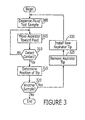
- Operations begin at Block 300 with dispensing of the fluid into the container.
- An aspirator tip is moved towards the fluid in a container in a gaseous atmosphere while detecting an amount of light provided to the aspirator tip that is reflected back through the aspirator tip to an optical detector from an outer surface of the aspirator tip (Block 305).
- the position of the aspirator tip is also detected while moving the aspirator tip.
- Contact with the fluid is detected when the amount of light detected changes by a selected amount (Block 310).
- the aspirator tip continues to move towards the fluid until contact is detected at Block 310.
- the position of the aspirator tip is determined when contact with the fluid is detected to detect the level of fluid (Block 315).
- the aspirator tip is a removable aspirator tip and, if a different fluid sample is to be detected (Block 320), the previously used aspirator tip can be removed from the aspirator body member of the aspirator system (Block 325). A different aspirator tip is installed on the aspirator body member (Block 330). Operations may then return to Block 300 through 315 to detect contact with the different fluid sample using the different aspirator tip so as to determine a level of the different fluid sample in the container.
- the aspirator body member may be part of an automated test apparatus and operations related to removing the aspirator tip and installing the different aspirator tip at Blocks 325 and 330 may be automatically performed by the test apparatus between tests of different fluid samples by the test apparatus and/or at other desired intervals for replacing the aspirator tip.
- a "different" aspirator tip may be an identical or distinct tip design and may be a new or re-used tip, for example, a cleaned and recycled tip.
- Operations for testing a sample in an automated test apparatus will now be further described with reference to the flow chart illustration of Figure 4 .
- operations begin at Block 400 by dispensing a test sample into a sample container in the apparatus.
- a level of the test sample in the container is then determined as will now be described with reference to Blocks 405 through 415.
- An aspirator tip is moved toward the sample in the container in a gaseous atmosphere while detecting an amount of light provided to the aspirator tip that is reflected back through the aspirator tip to an optical detector from an outer surface of the aspirator tip and while detecting a position of the aspirator tip (Block 405).
- Operations at Block 405 continue until contact with the sample is detected when the amount of light detected changes by a selected amount (Block 410).
- the position of the aspirator tip is determined when contact with the sample is detected to determine the level of the sample (Block 415).
- a reagent and/or other desired additive ingredient is added to the sample container including the dispensed test sample (Block 418). Subsequently, a portion of the sample is evacuated from the container using the aspirator tip (Block 420).
- a level of a remaining portion of the sample in the container is determined as will now be described with reference to Blocks 425 through 435.
- the aspirator tip is moved towards the remaining portion of the sample in the container in a gaseous atmosphere while detecting an amount of light provided to the aspirator tip that is reflected back through the aspirator tip to an optical detector from an outer surface of the aspirator tip (Block 425).
- a position of the aspirator tip is detected during movement of the aspirator tip at Block 425. Movement continues until contact of the aspirator tip with the remaining portion of the sample is detected when the amount of light detected changes by a selected amount (Block 430).
- the position of the aspirator tip is determined when contact with the remaining portion of the sample is detected to detect the level of the remaining portion of the sample (Block 435).
- the test of a sample in the automated test apparatus includes test protocols requiring different reagents and/or other desired additive ingredient(s) to be mixed with the sample. Accordingly, in such embodiments, if another reagent is to be used in the test (Block 440), the reagent is added (Block 445) and operations return to Block 405.
- the test apparatus may test additional test samples where it is desired to avoid cross contamination being introduced by the aspirator tip.
- the aspirator tip may be automatically removed from the aspirator body member to which the aspirator tip is removably coupled in the test apparatus (Block 455).
- a new aspirator tip may be automatically installed on the aspirator body member (Block 460). Operations may then return to Block 400 and the sequence of operations described previously may be repeated on the different test sample.
Landscapes
- Physics & Mathematics (AREA)
- Health & Medical Sciences (AREA)
- Life Sciences & Earth Sciences (AREA)
- Chemical & Material Sciences (AREA)
- Analytical Chemistry (AREA)
- Biochemistry (AREA)
- General Health & Medical Sciences (AREA)
- General Physics & Mathematics (AREA)
- Immunology (AREA)
- Pathology (AREA)
- Automatic Analysis And Handling Materials Therefor (AREA)
Description
- The present invention relates to devices for aspirating and detecting a level of fluids and, more particularly, to aspirator systems with optical level detection
- Aspirator systems are used in a variety of applications, such as automated test apparatus where tests are run on samples of a fluid, such as a blood sample. In such test apparatus, it may be necessary to serially and automatically dispense and/or evacuate test samples, reagents and the like from various containers. During such tests, it is sometimes desired to measure an amount of a sample in a container. An example of such an automated test apparatus are described, for example, in United States Patent No.
6,321,164 , entitled "Method and Apparatus for Predicting the Presence of an Abnormal Level of One or More Proteins in the Clotting Cascade." - Various approaches are known for sensing the presence, level and/or other characteristics of fluids. A variety of principles may be used to measure fluid level and/or other characteristics. One such approach is ultrasonic measurement. Another is using capacitance as used in a capacitance type sensor. Optical sensors may also be used.
- Document
EP 0 488 761 describes a liquid sampling instrument comprising a light transmissive pipette tip, a light source and a light receiving means, wherein contact of the pipette tip with a liquid sample can be detected by a change in the reflected light intensity. Said document does not describe an aspirator tip comprising at least one external diameter change discontinuity. Rather the pipette tips described and illustrated in the Figures ofEP 0 488 761 have the shape of an inverted truncated cone. These tips do not comprise an external diameter change discontinuity. - Document
EP 0 866 336 describes a pipetting device comprising a pipetting chip, a light irradiating body and a light receiving body, wherein the change in reflected light allows detection of the liquid level in the vessel. The pipetting chips shown inFigures 1 to 7 ofEP 0 866 336 do not comprise an external diameter change discontinuity, as they appear to have the same inverted truncated cone shape as shown inEP 0 488 761 . - A principal embodiment of the present invention comprises an aspirator system comprising:
- an aspirator body member having a fluid passageway extending therein and a first and second optical conductor configured to receive and/or transmit light therethrough;
- a drive mechanism coupled to the aspirator body member and configured to move the aspirator body member between an advanced position and a retracted position;
- an aspirator tip coupled to the aspirator body member at an end of the fluid passageway and having a fluid passageway therein extending from the end of the fluid passageway of the aspirator body member when coupled to the aspirator body member, the aspirator tip being coupled to the first and second optical conductors and comprising an optically transmissive material and being configured to conduct light from the first optical conductor to an outer surface of the aspirator tip and to conduct reflected light from the outer surface thereof to the second optical conductor; and
- a controller operatively coupled to the aspirator tip that is configured to detect contact of the aspirator tip with a fluid based on a changed level of light received from the aspirator tip through at least one of the first and second optical conductors responsive to a change of an index of refraction at the outer surface of the aspirator tip when the outer surface of the aspirator tip contacts the fluid and to determine a level of the fluid based on a position of the aspirator body member when contact of the aspirator tip with the fluid is detected, and
- wherein the aspirator tip has at least one external diameter change discontinuity (224) thereon, configured such that a portion of light received from the first optical conductor that is reflected back through the aspirator tip to the second optical conductor from an outer surface of the aspirator tip changes when the at least one external diameter change discontinuity contacts the fluid..
- In further embodiments of the present invention, the aspirator tip is a disposable tip removably coupled to the aspirator body member. The aspirator tip may be configured to be automatically removed from the aspirator body member by the aspirator system.
- In some embodiments of the present invention, the aspirator system includes a light source optically coupled to the first optical conductor and a light detector circuit optically coupled to the second optical conductor that outputs a detected light level signal. The controlled may be configured to detect contact of the aspirator tip with a fluid based on the detected light level signal. The first and second optical conductors may be light pipes and the aspirator tip may include a first and a second light pipe port, respectively, coupled to the first and second optical conductors of the aspirator body member. The first and second optical conductors may be optical fibers coupled to the aspirator body member.
- In further embodiments of the present invention, a position detector is coupled to the controller and is configured to output a position signal corresponding to the location of the aspirator body member to the controller. The position detector may be a motor encoder coupled to the drive mechanism and the position signal may be an encoder count. The light detector circuit may be configured to distinguish light received directly from the light source and light reflected from an outer surface of the aspirator tip based on respective amplitudes thereof.
- In certain embodiments of the present invention, the aspirator tip is configured to conduct light from the first optical conductor to an outer surface thereof and to conduct reflected light from the outer surface thereof to the second optical conductor. The aspirator tip may be a longitudinally extending, substantially cylindrical member having a tapered tip on a longitudinal end thereof displaced from the aspiratory body member. The fluid passageway of the aspirator tip may extend longitudinally from the aspirator body member to the tapered tip of the aspirator tip and the fluid passageway of the aspirator tip may change diameter in the tapered tip. The aspirator tip may have at least one external diameter change discontinuity thereon and the detected light level signal may change when the at least one external diameter change discontinuity contacts the fluid.
- In further embodiments of the present invention, methods for detecting a level of a fluid in a container in an aspirator system include dispensing the fluid into the container. An aspirator tip is moved toward the fluid in the container in a gaseous atmosphere while the aspirator system detects an amount of light provided to the aspirator tip that is reflected back through the aspirator tip to an optical detector from an outer surface of the aspirator tip and while detecting a position of the aspirator tip. Contact with the fluid is detected when the amount of light detected changes by a selected amount. The position of the aspirator tip is determined when contact with the fluid is detected to thereby detect the level of the fluid. The aspirator tip may be a removable aspirator tip and detecting contact with the fluid may be followed by removing the aspirator tip from an aspirator body member and installing a different aspirator tip on the aspirator body member. Contact with a different fluid sample is detected using the different aspirator tip. The aspirator body member may be part of an automated test apparatus and removing the aspirator tip and installing the different aspirator tip may be automatically performed by the test apparatus between tests of different fluid samples and/or types by the test apparatus.
- In other embodiments of the present invention, methods o in an automated test apparatus of testing a test sample dispensed into a sample container in the apparatus. A level of the test sample in the container is determined by moving an aspirator tip towards the sample in the container in a gaseous atmosphere while detecting an amount of light provided to the aspirator tip that is reflected back through the aspirator tip to an optical detector from an outer surface of the aspirator tip and while detecting a position of the aspirator tip. Contact with the sample is determined when the amount of light detected changes by a selected amount and the position of the aspirator tip is determined when contact with the sample is detected to determine the level of the sample. A reagent is added to the sample container. A portion of the sample is evacuated (withdrawn) from the container with the aspirator tip.
- A level of a remaining portion of the sample in the container is determined after evacuating a portion of the sample. The aspirator tip is moved towards the remaining portion of the sample in the container in a gaseous atmosphere while detecting an amount of light provided to the aspirator tip that is reflected back through the aspirator tip to an optical detector from an outer surface of the aspirator tip and while detecting a position of the aspirator tip. Contact with the remaining portion of the sample is determined when the amount of light detected changes by a selected amount. The position of the aspirator tip is determined when contact with the remaining portion of the sample is detected to detect the level of the remaining portion of the sample.
- In further embodiments of the present invention, adding a reagent, evacutating a portion and determining a level are repeated for at least one additional reagent. Determining a level of a remaining portion of the sample may be followed by automatically removing the aspirator tip from an aspirator body member to which the aspirator tip is removably coupled in the test apparatus and automatically installing a different aspirator tip on the aspirator body member. Dispensing a test sample into a sample container in the apparatus, determining a level of the test sample in the container, adding a reagent to the sample container, evacuating a portion of the sample from the container with the aspirator tip and determining a level of a remaining portion of the sample in the container after evacuating a portion of the sample may be repeated for a different test sample using the different aspirator tip.
- In other embodiments of the present invention, aspirator systems include an aspirator body member having a fluid passageway extending therein and a first and second optical conductor configured to receive and/or transmit light therethrough. A removable aspirator tip is coupled to the aspirator body member at an end of the fluid passageway and has a fluid passageway therein extending from the end of the fluid passageway of the aspirator body member when coupled to the aspirator body member. The aspirator tip is coupled to the first and second optical conductors and is an optically transmissive material. The aspirator tip is configured to reflect a first portion of light received from the first optical conductor light back through the aspirator tip to the second optical conductor from an outer surface of the aspirator tip when the outer surface is in contact with a gaseous atmosphere and a second portion of the light received from the first optical conductor, different from the first portion, when the outer surface is in contact with a fluid.
- In further embodiments of the present invention, aspirator systems include an aspirator body member having a fluid passageway extending therein and a first and second optical conductor configured to receive and/or transmit light therethrough. A drive mechanism is coupled to the aspirator body member and configured to move the aspirator body member between an advanced position and a retracted position. A detachable aspirator tip is removably coupled to the aspirator body member at an end of the fluid passageway and has a fluid passageway therein extending from the end of the fluid passageway of the aspirator body member when coupled to the aspirator body member. The aspirator tip includes optical conductors thereon removably coupled to the first and second optical conductor of the aspirator body member respectively. A controller coupled to the aspirator tip is configured to detect contact of the aspirator tip with a fluid based on a level of light received from the aspirator tip through at least one of the first and second optical conductors and to determine a level of the fluid based on a position of the aspirator body member when contact of the aspirator tip with the fluid is detected.
- The accompanying drawings, which form a part of the specification, illustrate embodiments of the present invention. The drawings and description together serve to fully explain the invention. In the drawings,
-
Figure 1 is a schematic block diagram illustrating a test apparatus including an aspirator system in accordance with some embodiments of the present invention; -
Figure 2A is a cross-sectional side view illustrating an aspirator tip according to some embodiments of the present invention; -
Figure 2B is a top view of the aspirator tip ofFigure 2A ; -
Figure 2C is a top view of an aspirator tip in accordance with other embodiments of the present invention; -
Figure 3 is a flowchart illustrating operations for detecting a level of a fluid in a container in accordance with some embodiments of the present invention; and -
Figure 4 is a flowchart illustrating operations for testing a sample in an automated test apparatus in accordance with some embodiments of the present invention. - The present invention now will be described more fully hereinafter with reference to the accompanying drawings, in which embodiments of the invention are shown. This invention may, however, be embodied in many different forms and should not be construed as limited to the embodiments set forth herein; rather, these embodiments are provided so that this disclosure will be thorough and complete, and will fully convey the scope of the invention to those skilled in the art. In the drawings, like numbers refer to like elements throughout. The terms "upwardly", "downwardly", "vertical", "horizontal", "bottom", "top" and the like are used herein for the purpose of explanation only.
- As will be described further herein, various embodiments of the present invention may use a disposable aspirator tip, which incorporates a light pipe into the tip itself, to determine a level of a fluid in a container. The aspirator tip may be removed and replaced between sample runs, for example, to mitigate cross-contamination and/or to prevent other items from being added to a sample on the inside of a container, such as a cuvette. The use of disposable optics in the aspirator tip for level sensing may beneficially provide for fluid level detection through contact with only a single sample, which may help eliminate cross-contamination between samples and subsequent runs. Such may be particularly useful for testing biological samples, such as, but not limited to, blood or plasma samples. The aspirator tip may be configured to use a change in the index of refraction between a gas and the fluid sample being measured to change the amount of light reflected from an outer surface of the tip, back up the tip. As such, when the tip contacts the fluid, the reflected light intensity may change. Various approaches may be taken to calculate a level of the fluid based on detection of the point of contact as will be understood by those of skill in the art.
- Referring now to
Figure 1 , atest apparatus 100 including anaspirator system 102 according to some embodiments of the present invention will now be further described. Thetest apparatus 100 ofFigure 1 is illustrated schematically including a schematic illustration of features, components and/or aspects of anaspirator system 102 that may be used in accordance with various embodiments of the present invention. It will be understood that thetest apparatus 100 will generally include various other features, components and/or aspects related to the particular tests performed by thetest apparatus 100, which other aspects are generally known and will not be further described herein except as they may relate to the aspirator systems of the present invention. - The
aspirator system 102 of the embodiments ofFigure 1 is configured to measure the level of a fluid sample in thesample container 165. In addition to measuring the level of the fluid sample, in various embodiments of the present invention theaspirator system 102 may be configured to add and/or evacuate fluid samples to/from thesample container 165 and/or other containers in thetest apparatus 100, such as other sample containers, reagent containers and the like, and to move fluids between respective ones of such containers based on the requirements of a test being performed on thetest apparatus 100. Accordingly, the aspirator systems of the present invention may perform various conventional operations of known aspirator systems, which conventional aspects will not be further described herein except as they relate to various embodiments of the present invention. - As shown in the embodiments of
Figure 1 , theaspirator system 102 includes anaspirator body member 105 and anaspirator tip 110 coupled to theaspirator body member 105. Theaspirator system 102 may further include adrive mechanism 145 coupled to theaspirator body member 105 and acontroller 150, which may be operatively coupled to theaspirator tip 110 through thedetector circuit 155. Thedetector circuit 155 may include an optical detector that detects reflected light from theaspirator tip 110 through theoptical conductor 120. Alight source 160 may be optically coupled to theaspirator tip 110 through theoptical conductor 130. - The
aspirator body member 105 may have afluid passageway 107 extending therein for delivering a sample to and/or evacuating/removing a sample from thesample container 165 and/or other containers and/or channels associated with thetest apparatus 100. Theoptical conductors Figure 1 can be coupled to theaspirator body 105 byconnectors Figure 1 , theoptical conductors aspirator body 105 rather than being attached to an outer surface of theaspirator body 105. In any event, theoptical conductors aspirator body 105 are configured to provide light to and/or receive reflected light from theaspirator tip 110. - The
aspirator tip 110 is coupled to theaspirator body 105 at an end of thefluid passageway 107. Theaspirator tip 110 is shown as including afluid passageway 112 therein that extends from the end of thefluid passageway 107 when theaspirator tip 110 is coupled to theaspirator body 105 to provide a continuous fluid passageway through theaspirator body 105 andtip 110. Theaspirator tip 110 may be optically coupled to theoptical conductors light pipe ports 115, 140. Theaspirator tip 110 may be an optically transmissive material to allow transmission of light therethrough and may be a disposable tip removably coupled to theaspirator body 105. In particular, thetest apparatus 100 and theaspirator tip 110 may be configured to allow theaspirator system 102 to automatically remove and replace theaspirator tip 110, for example, between test cycles and/or on different test samples and/or the like. - In particular embodiments of the present invention, the
aspirator tip 110 is configured to detect contact with a fluid sample based on a change in an index of refraction of a fluid contacting an outer surface thereof causing a different amount of internal refraction of light then when theaspirator tip 110 is in a gaseous atmosphere, such as air. Theaspirator tip 110 may be configured to conduct light from theoptical conductor 130 to an outer surface 111 of theaspirator tip 110 and to conduct reflected light from the outer surface 111 of theaspirator tip 110 to theoptical conductor 120. Thus, a first portion of the light from theoptical conductor 130 may be reflected back to theoptical conductor 120 when the outer surface of theaspirator tip 110 is in contact with a gaseous atmosphere and a second, different portion of the light from theoptical conductor 120 may be reflected back through theaspirator tip 110 when theaspirator tip 110 outer surface is in contact with a fluid sample in thesample container 165. - The
drive mechanism 145, in some embodiments of the present invention, is configured to automatically move theaspirator body member 105 between an advanced position and a retracted position. As illustrated inFigure 1 , movement toward thesample container 165 in the direction ofarrow 170 corresponds to movement to the advanced position and movement away from thesample container 165 in the direction ofarrow 175 corresponds to movement to the retracted position. Thedrive mechanism 145 may also be configured to provide for movement in other directions associated with different aspects of an automated test cycle of thetest apparatus 100. - For the illustrated embodiments of
Figure 1 , aposition detector 147 is associated with thedrive mechanism 145. Theposition detector 147 is illustrated as coupled to thecontroller 150 to output a position signal to thecontroller 150 that corresponds to a location of theaspirator body member 105, either in absolute terms and/or relative to another reference point in the test apparatus, such as thesample container 165. In some embodiments of the present invention, theposition detector 147 is a motor encoder coupled to thedrive mechanism 145, in which case, the position signal to thecontroller 150 may be an encoder count. However, other types of position detectors, including those providing direct detection of the position of theaspirator body member 105, for example, by optical, magnetic and/or electromechanical sensors, are also suitable for use with various embodiments of the present invention. Accordingly, while shown in association with thedrive mechanism 145 in the embodiments ofFigure 1 , theposition detector 147 need not be associated with thedrive mechanism 145. - The
controller 150 may be configured to detect contact of theaspirator tip 110 with a fluid in thesample container 165 based on a level of light received from theaspirator tip 110 through theoptical conductor 120. As illustrated in the embodiments ofFigure 1 , the amount of light received by theoptical conductor 120 is detected by thelight detector circuit 155. For example, thelight detector circuit 155 maybe configured to distinguish light received directly from thelight source 160 and light reflected from an outer surface of theaspirator tip 110 based on respective amplitudes thereof. Thelight detector circuit 155 may output a detected light level signal to thecontroller 150, based on which thecontroller 150 may determine when contact with a fluid occurs. Alternatively, thelight detector circuit 155 maybe configured to detect contact with the fluid itself based on the level of light received from theoptical conductor 120 and then send a fluid contact signal to thecontroller 150 rather than an output signal proportional to the amount of light detected. In yet other embodiments of the present invention, thedetector circuit 155 may be implemented as part of thecontroller 150 and thecontroller 150 may be directly coupled to theoptical conductor 120. In any event, thecontroller 150 may then determine a level of a fluid sample in thesample container 165 based on a position of theaspirator body member 105, including theaspirator tip 110 coupled thereto, when contact of theaspirator tip 110 with the fluid sample is detected. - Further embodiments of the present invention will now be described with reference to
Figures 2A through 2C. Figure 2A is a side cross-sectional view of anaspirator tip 210 according to some embodiments of the present invention.Figures 2B and 2C are top views of theaspirator tip 210 illustrating alternative coupling locations for optical conductors to theaspirator tip 210. As shown inFigure 2A , theaspirator tip 210 is a longitudinally extending, generally cylindrical member having anupper body portion 225 and a taperedlower body portion 230. Thelower body portion 230 for the embodiments ofFigure 2A is divided into afirst part 230a and asecond part 230b by an externaldiameter change discontinuity 224. The external diameter change discontinuity may provide a change in the detected light level when it contacts a fluid. As such, for the embodiments ofFigure 2A , it may be possible to detect both the initial contact of thesecond part 230b with the fluid and when thesecond part 230b is fully inserted into the fluid. The externaldiameter change discontinuity 224 is illustrated as a stepped outer surface inFigure 2A . However, the discontinuity may take a variety of other forms, such as angled or curved surfaces, providing a change in detected light level. - A
fluid passageway 212 extends through theaspirator tip 210. Thefluid passageway 212 includes anupper part 212a having a first diameter, alower part 212c having a second, smaller diameter and atapered part 212b therebetween. Thepassageway 212 extends through theaspirator tip 210 from afirst end 222 configured to couple to theaspirator body member 105 and asecond end 221 including an opening in theaspirator tip 210 for receiving fluid from and/or dispensing fluid into thesample container 165. Thefluid passageway 212 changes diameter as it extends through the taperedlower body portion 230, both due to thetapered part 212b and, for the illustrated embodiments, due to the internaldiameter change discontinuity 223. -
Figures 2A through 2C also illustrate various embodiments oflight pipe ports aspirator tip 210. Thelight pipe ports first end 222 of theaspirator tip 210. As shown inFigure 2B , therespective ports Figure 2C , in other embodiments of the present invention, thelight pipe ports - In particular embodiments of the present invention, the
aspirator tip 210 may have an overall length of about 1.735 inches. Theupper body member 225 may have a length of about 0.55 inches and a diameter of about 0.5 inches. Thepassageway 212 may have a diameter at thefirst end 222 of about 0.28 inches and a minimum diameter at the opposite end thereof of about 0.09 inches. The innerdiameter step discontinuity 223 may drop the passageway diameter from about 0.28 inches to about 0.23 inches. The minimum outer diameter of theaspirator tip 210 at thesecond end 221 thereof may be about 0.14 inches. And theexternal diameter discontinuity 224 may be positioned about 0.295 inches from theend 221 longitudinally. The innerdiameter step discontinuity 223 may be positioned about 0.675 inches from thefirst end 222 longitudinally. The taperedportion 212b of thepassageway 212 may extend longitudinally about 0.36 inches. - In some embodiments of the present invention, optical fibers may be integrally attached, for example, in an adhesive manner (such as tape or glue), by molding and/or by ultrasonic welding to the aspirator tip 110,210 rather than or in addition to providing the
aspirator tip 110 itself as an optically transmissive member to act as a light pipe. Theaspirator tip 110 may still be detachable in such embodiments by providing for detachment of the optical fibers from the tip and/oraspirator body member 105 as well. If cross-contamination is a problem for a particular application, the attached optical fibers may be decoupled from the aspirator body member and different optical fibers associated with a different aspirator tip may then be coupled to the aspirator body member. - Referring now to the flow chart illustration of
Figure 3 , various embodiments of methods for detecting a level of a fluid in a container in an aspirator system will now be described. Operations begin atBlock 300 with dispensing of the fluid into the container. An aspirator tip is moved towards the fluid in a container in a gaseous atmosphere while detecting an amount of light provided to the aspirator tip that is reflected back through the aspirator tip to an optical detector from an outer surface of the aspirator tip (Block 305). The position of the aspirator tip is also detected while moving the aspirator tip. Contact with the fluid is detected when the amount of light detected changes by a selected amount (Block 310). The aspirator tip continues to move towards the fluid until contact is detected atBlock 310. The position of the aspirator tip is determined when contact with the fluid is detected to detect the level of fluid (Block 315). - In some embodiments of the present invention, the aspirator tip is a removable aspirator tip and, if a different fluid sample is to be detected (Block 320), the previously used aspirator tip can be removed from the aspirator body member of the aspirator system (Block 325). A different aspirator tip is installed on the aspirator body member (Block 330). Operations may then return to
Block 300 through 315 to detect contact with the different fluid sample using the different aspirator tip so as to determine a level of the different fluid sample in the container. The aspirator body member may be part of an automated test apparatus and operations related to removing the aspirator tip and installing the different aspirator tip atBlocks - Operations for testing a sample in an automated test apparatus according to various embodiments of the present invention will now be further described with reference to the flow chart illustration of
Figure 4 . As shown inFigure 4 , operations begin at Block 400 by dispensing a test sample into a sample container in the apparatus. A level of the test sample in the container is then determined as will now be described with reference toBlocks 405 through 415. An aspirator tip is moved toward the sample in the container in a gaseous atmosphere while detecting an amount of light provided to the aspirator tip that is reflected back through the aspirator tip to an optical detector from an outer surface of the aspirator tip and while detecting a position of the aspirator tip (Block 405). Operations atBlock 405 continue until contact with the sample is detected when the amount of light detected changes by a selected amount (Block 410). The position of the aspirator tip is determined when contact with the sample is detected to determine the level of the sample (Block 415). - A reagent and/or other desired additive ingredient is added to the sample container including the dispensed test sample (Block 418). Subsequently, a portion of the sample is evacuated from the container using the aspirator tip (Block 420).
- After evacuation of a portion of the sample, a level of a remaining portion of the sample in the container is determined as will now be described with reference to
Blocks 425 through 435. The aspirator tip is moved towards the remaining portion of the sample in the container in a gaseous atmosphere while detecting an amount of light provided to the aspirator tip that is reflected back through the aspirator tip to an optical detector from an outer surface of the aspirator tip (Block 425). A position of the aspirator tip is detected during movement of the aspirator tip atBlock 425. Movement continues until contact of the aspirator tip with the remaining portion of the sample is detected when the amount of light detected changes by a selected amount (Block 430). The position of the aspirator tip is determined when contact with the remaining portion of the sample is detected to detect the level of the remaining portion of the sample (Block 435). - In some embodiments of the present invention, the test of a sample in the automated test apparatus includes test protocols requiring different reagents and/or other desired additive ingredient(s) to be mixed with the sample. Accordingly, in such embodiments, if another reagent is to be used in the test (Block 440), the reagent is added (Block 445) and operations return to
Block 405. - In further embodiments of the present invention, the test apparatus may test additional test samples where it is desired to avoid cross contamination being introduced by the aspirator tip. In such embodiments, when an additional sample is to be tested (Block 450), the aspirator tip may be automatically removed from the aspirator body member to which the aspirator tip is removably coupled in the test apparatus (Block 455). A new aspirator tip may be automatically installed on the aspirator body member (Block 460). Operations may then return to Block 400 and the sequence of operations described previously may be repeated on the different test sample.
- The foregoing is illustrative of the present invention and is not to be construed as limiting thereof. Although a few exemplary embodiments of this invention have been described, those skilled in the art will readily appreciate that many modifications are possible in the exemplary embodiments without materially departing from the novel teachings and advantages of this invention. Accordingly, all such modifications are intended to be included within the scope of this invention as defined in the claims. In the claims, means-plus-function clauses are intended to cover the structures described herein as performing the recited function and not only structural equivalents but also equivalent structures. Therefore, it is to be understood that the foregoing is illustrative of the present invention and is not to be construed as limited to the specific embodiments disclosed, and that modifications to the disclosed embodiments, as well as other embodiments, are intended to be included within the scope of the appended claims. The invention is defined by the following claims, with equivalents of the claims to be included therein.
Claims (19)
- An aspirator system (102) comprising:an aspirator body member (105) having a fluid passageway (107) extending therein and a first and second optical conductor (120, 130) configured to receive and/or transmit light therethrough;a drive mechanism (145) coupled to the aspirator body member and configured to move the aspirator body member between an advanced position and a retracted position;an aspirator tip (110) coupled to the aspirator body member at an end of the fluid passageway and having a fluid passageway therein extending from the end of the fluid passageway of the aspirator body member when coupled to the aspirator body member, the aspirator tip being coupled to the first and second optical conductors and comprising an optically transmissive material and being configured to conduct light from the first optical conductor to an outer surface (111) of the aspirator tip and to conduct reflected light from the outer surface thereof to the second optical conductor; anda controller (150) operatively coupled to the aspirator tip that is configured to detect contact of the aspirator tip with a fluid based on a changed level of light received from the aspirator tip through at least one of the first and second optical conductors responsive to a change of an index of refraction at the outer surface of the aspirator tip when the outer surface of the aspirator tip contacts the fluid and to determine a level of the fluid based on a position of the aspirator body member when contact of the aspirator tip with the fluid is detected,characterized in that the aspirator tip has at least one external diameter change discontinuity (224) thereon, configured such that a portion of light received from the first optical conductor that is reflected back through the aspirator tip to the second optical conductor from an outer surface of the aspirator tip changes when the at least one external diameter change discontinuity contacts the fluid.
- The aspirator system of claim 1 wherein the aspirator tip is a disposable tip removably coupled to the aspirator body member.
- The aspirator system of claim 2 wherein the aspirator tip is configured to be automatically removed from the aspirator body member by the aspirator system.
- The aspirator system of claim 2 further comprising:a light source (160) optically coupled to the first optical conductor; anda light detector circuit (155) optically coupled to the second optical conductor that outputs a detected light level signal; andwherein the controller is configured to detect contact of the aspirator tip with a fluid based on the detected light level signal.
- The aspirator system of claim 4 wherein the first and second optical conductors comprise light pipes and wherein the aspirator tip includes a first and a second light pipe port respectively coupled to the first and second optical conductors of the aspirator body member.
- The aspirator system of claim 4 wherein the first and second optical conductors comprise optical fibers coupled to the aspirator body member.
- The aspirator system of claim 4 further comprising a position detector coupled to the controller that outputs a position signal corresponding to the location of the aspirator body member to the controller.
- The aspirator system of claim 7 wherein the position detector comprises a motor encoder coupled to the drive mechanism and wherein the position signal comprises an encoder count.
- The aspirator system of claim 1 wherein the aspirator tip comprises a longitudinally extending, generally cylindrical member having a tapered tip on a longitudinal end thereof displaced from the aspirator body member.
- The aspirator system of claim 9 wherein the fluid passageway of the aspirator tip extends longitudinally from the aspirator body member to the tapered tip of the aspirator tip and wherein fluid passageway of the aspirator tip changes diameter in the tapered tip.
- The aspirator system of claim 9 wherein the aspirator tip has at least one external diameter change discontinuity (224) thereon and wherein the detected light level signal changes when the at least one external diameter change discontinuity contacts the fluid.
- The aspirator system of claim 1 wherein the light detector circuit is configured to distinguish light received directly from the light source and light reflected from the outer surface of the aspirator tip based on respective amplitudes thereof.
- An aspirator system according to claim 1, wherein the aspirator tip is detachable and is removably coupled to the aspirator body member; and the aspirator tip including optical conductors thereon removably coupled to the first and second optical conductor of the aspirator body member respectively.
- A method for detecting a level of a fluid in a container in an aspirator system, the method comprising:moving an aspirator tip toward a fluid in the container in a gaseous atmosphere, the aspirator tip comprising an optically transmissive material and being configured to transmit light to an outer surface of the aspirator tip, wherein the aspirator tip has at least one external diameter change discontinuity (224) thereon, and detecting an amount of light provided to the aspirator tip that is reflected back through the aspirator tip to an optical detector from the outer surface of the aspirator tip and while detecting a position of the aspirator tip;detecting contact with the fluid and detecting contact of the at least one external diameter change discontinuity (224) with the fluid when the amount of reflected light detected changes by a selected amount; anddetermining the position of the aspirator tip when contact with the fluid is detected to detect the level of the fluid and determining the position of the at least one external diameter change discontinuity (224) when contact with the fluid is detected.
- The method of claim 14 wherein the aspirator tip is a removable aspirator tip and wherein detecting contact with the fluid is followed by:removing the aspirator tip from an aspirator body member;installing a different aspirator tip on the aspirator body member; anddetecting contact with a different fluid sample using the different aspirator tip.
- The method of claim 15 wherein the aspirator body member is part of an automated test apparatus and wherein removing the aspirator body member is part of an automated test apparatus and wherein removing the aspirator tip and installing the new aspirator tip are automatically performed by the test apparatus between tests of different fluid samples.
- A method of testing a sample in an automated test apparatus, comprising:determining a level of test sample in a container of the apparatus according to the method of claim 15;adding an additive ingredient to the sample container;evacuating a portion of the sample from the container with the aspirator tip; anddetermining a level of a remaining portion of the sample in the container after evacuating a portion of the sample by:moving the aspirator tip towards the remaining portion of the sample in the container in a gaseous atmosphere while detecting an amount of light provided to the aspirator tip that is reflected back through the aspirator tip to an optical detector from an outer surface of the aspirator tip and while detecting a position of the aspirator tip;detecting contact with the remaining portion of the sample when the amount of light detected changes by a selected amount; anddetermining the position of the aspirator tip when contact with the remaining portion of the sample is detected to detect the level of the remaining portion of the sample.
- The method of claim 17 further comprising repeating adding a reagent, evacuating a portion and determining a level for at least one additional reagent.
- The method of claim 17 wherein determining a level of a remaining portion of the sample is followed by:automatically removing the aspirator tip from an aspirator body member to which the aspirator tip is removably coupled in the test apparatus;automatically installing a new aspirator tip on the aspirator body member; andrepeating determining a level of the test sample in the container, adding an additive ingredient to the sample container, evacuating a portion of the sample from the container with the aspirator tip and determining a level of a remaining portion of the sample in the container after evacuating a portion of the sample for a different test sample.
Applications Claiming Priority (2)
| Application Number | Priority Date | Filing Date | Title |
|---|---|---|---|
| US10/851,724 US7537735B2 (en) | 2004-05-21 | 2004-05-21 | Aspirator systems having an aspirator tip optical level detector and methods for using the same |
| PCT/US2005/006971 WO2005119270A1 (en) | 2004-05-21 | 2005-03-01 | Aspirator systems having an aspirator tip used as optical level detector and methods for using the same |
Publications (2)
| Publication Number | Publication Date |
|---|---|
| EP1756587A1 EP1756587A1 (en) | 2007-02-28 |
| EP1756587B1 true EP1756587B1 (en) | 2013-10-02 |
Family
ID=34962566
Family Applications (1)
| Application Number | Title | Priority Date | Filing Date |
|---|---|---|---|
| EP05724502.9A Expired - Lifetime EP1756587B1 (en) | 2004-05-21 | 2005-03-01 | Aspirator systems having an aspirator tip used as optical level detector and methods for using the same |
Country Status (3)
| Country | Link |
|---|---|
| US (1) | US7537735B2 (en) |
| EP (1) | EP1756587B1 (en) |
| WO (1) | WO2005119270A1 (en) |
Cited By (2)
| Publication number | Priority date | Publication date | Assignee | Title |
|---|---|---|---|---|
| EP3226004A1 (en) | 2016-03-30 | 2017-10-04 | CTC Analytics AG | Method for operating a metering device |
| EP3567359A1 (en) | 2018-05-08 | 2019-11-13 | Sartorius Biohit Liquid Handling Oy | Liquid handling system and a method for analysing a state of a tip |
Families Citing this family (14)
| Publication number | Priority date | Publication date | Assignee | Title |
|---|---|---|---|---|
| US20030082152A1 (en) * | 1999-03-10 | 2003-05-01 | Hedrick Marc H. | Adipose-derived stem cells and lattices |
| KR20050026404A (en) | 2002-06-19 | 2005-03-15 | 팔로마 메디칼 테크놀로지스, 인코포레이티드 | Method and apparatus for photothermal treatment of tissue at depth |
| US7856985B2 (en) | 2005-04-22 | 2010-12-28 | Cynosure, Inc. | Method of treatment body tissue using a non-uniform laser beam |
| US7586957B2 (en) | 2006-08-02 | 2009-09-08 | Cynosure, Inc | Picosecond laser apparatus and methods for its operation and use |
| US8703492B2 (en) | 2007-04-06 | 2014-04-22 | Qiagen Gaithersburg, Inc. | Open platform hybrid manual-automated sample processing system |
| US7985375B2 (en) * | 2007-04-06 | 2011-07-26 | Qiagen Gaithersburg, Inc. | Sample preparation system and method for processing clinical specimens |
| US20090076489A1 (en) | 2007-06-08 | 2009-03-19 | Richard Shaun Welches | Thermal surgery safety apparatus and method |
| US9953141B2 (en) | 2009-11-18 | 2018-04-24 | Becton, Dickinson And Company | Laboratory central control unit method and system |
| KR102342629B1 (en) | 2012-04-18 | 2021-12-22 | 싸이노슈어, 엘엘씨 | Picosecond laser apparatus and methods for treating target tissues with same |
| WO2014145707A2 (en) | 2013-03-15 | 2014-09-18 | Cynosure, Inc. | Picosecond optical radiation systems and methods of use |
| EP2823889B1 (en) * | 2013-07-10 | 2016-10-19 | Roche Diagniostics GmbH | Device and method for biological sample collection and inspection |
| WO2015189464A1 (en) | 2014-06-10 | 2015-12-17 | Thermo Fisher Scientific Oy | Pipette comprising imagine device element |
| US11069929B1 (en) | 2016-05-24 | 2021-07-20 | NDSL, Inc. | Apparatuses and methods for optically monitoring fluid level in a container, such as a battery, using a non-contact optical detector on an outside surface of the container |
| CN112042066A (en) | 2018-02-26 | 2020-12-04 | 赛诺秀股份有限公司 | Q-switched cavity-tilting subnanosecond laser |
Family Cites Families (30)
| Publication number | Priority date | Publication date | Assignee | Title |
|---|---|---|---|---|
| US3683196A (en) * | 1970-11-27 | 1972-08-08 | Texas Instruments Inc | Differential fluid level detector |
| US3995167A (en) * | 1974-09-19 | 1976-11-30 | The J. M. Ney Company | Fiberoptic fluid level sensing mechanism |
| US4038650A (en) * | 1975-10-14 | 1977-07-26 | Martin Evans | Fluid level detector and probe assembly |
| DE3113248C2 (en) | 1981-04-02 | 1987-03-19 | Eppendorf Gerätebau Netheler + Hinz GmbH, 2000 Hamburg | Device for withdrawing liquids from analytical-scale containers |
| US4477190A (en) * | 1981-07-20 | 1984-10-16 | American Hospital Supply Corporation | Multichannel spectrophotometer |
| DE3248409A1 (en) | 1982-12-28 | 1984-06-28 | Franz-Josef Prof. Dr. 3550 Marburg Haberich | Sampling device |
| US4764671A (en) * | 1986-10-03 | 1988-08-16 | Kollmorgen Corporation | Fiber optic fluid sensor using coated sensor tip |
| GB2212262B (en) * | 1987-11-09 | 1992-07-22 | Solinst Canada Ltd | Liquid level detector |
| US4880971A (en) * | 1988-02-17 | 1989-11-14 | Danisch Lee A | Fiber optic liquid level sensor |
| US4846003A (en) * | 1988-06-08 | 1989-07-11 | Beckman Instruments, Inc. | Acoustic impedance system for pipette tip detection |
| US4950885A (en) * | 1989-05-08 | 1990-08-21 | I.V.P. Co. | Fluid coupled fiber optic sensor |
| DE3934344A1 (en) * | 1989-10-14 | 1991-04-25 | Bodenseewerk Perkin Elmer Co | CONTROL DEVICE FOR THE SUCTION TUBE IN AUTOMATIC SAMPLER |
| US5084614A (en) * | 1990-09-21 | 1992-01-28 | Tsi Incorporated | Optical single particle detector with lenseless fiber optic probe |
| JP2969935B2 (en) | 1990-11-30 | 1999-11-02 | 東ソー株式会社 | Liquid metering device |
| US5271734A (en) * | 1991-10-01 | 1993-12-21 | Hideyuki Takeuchi | Light-emitting dental probe for measuring gum pockets |
| JP2725917B2 (en) * | 1991-10-04 | 1998-03-11 | アロカ株式会社 | Blood sample dispensing method |
| US5267474A (en) * | 1992-10-23 | 1993-12-07 | Kohler Co. | Liquid-level sensor |
| US5439449A (en) * | 1994-04-22 | 1995-08-08 | E-Z-Em, Inc. | Flow visualization needle system |
| JPH08338849A (en) | 1995-04-11 | 1996-12-24 | Precision Syst Sci Kk | Liquid suction determination method and dispensing device driven and controlled by this method |
| US6321164B1 (en) * | 1995-06-07 | 2001-11-20 | Akzo Nobel N.V. | Method and apparatus for predicting the presence of an abnormal level of one or more proteins in the clotting cascade |
| CA2177658A1 (en) * | 1995-07-10 | 1997-01-11 | Kurukundi Ramesh Murthy | Volume detection apparatus and method |
| US6158269A (en) * | 1995-07-13 | 2000-12-12 | Bayer Corporation | Method and apparatus for aspirating and dispensing sample fluids |
| US5882194A (en) * | 1995-11-27 | 1999-03-16 | Davis; Warren | Illuminated suction tool with a disposable tip |
| US5897509A (en) * | 1996-06-21 | 1999-04-27 | Aisin Seiki Kabushiki Kaisha | Probe for measuring periodontal pocket depth |
| US5969620A (en) * | 1998-07-24 | 1999-10-19 | Okulov; Pavel D. | Water level alarm |
| EP1054250B1 (en) * | 1999-01-25 | 2002-09-04 | Hamamatsu Photonics K.K. | Pipette adaptor, pipette for absorbance measurement, method and apparatus for absorbance measurement |
| US6280187B1 (en) * | 2000-02-11 | 2001-08-28 | Charles E. Slone | Dental hand tool for interproximal dental restorations |
| US6602072B2 (en) * | 2001-09-20 | 2003-08-05 | Debra Burney | Disposable deformable high volume aspirator |
| US7517694B2 (en) * | 2002-07-26 | 2009-04-14 | Ortho-Clinical Diagnostics, Inc. | Metering tip with internal features to control fluid meniscus and oscillation |
| US7592185B2 (en) * | 2004-02-17 | 2009-09-22 | Molecular Bioproducts, Inc. | Metering doses of sample liquids |
-
2004
- 2004-05-21 US US10/851,724 patent/US7537735B2/en not_active Expired - Fee Related
-
2005
- 2005-03-01 EP EP05724502.9A patent/EP1756587B1/en not_active Expired - Lifetime
- 2005-03-01 WO PCT/US2005/006971 patent/WO2005119270A1/en not_active Ceased
Cited By (3)
| Publication number | Priority date | Publication date | Assignee | Title |
|---|---|---|---|---|
| EP3226004A1 (en) | 2016-03-30 | 2017-10-04 | CTC Analytics AG | Method for operating a metering device |
| US10900983B2 (en) | 2016-03-30 | 2021-01-26 | Ctc Analytics Ag | Method for operating a dosing device |
| EP3567359A1 (en) | 2018-05-08 | 2019-11-13 | Sartorius Biohit Liquid Handling Oy | Liquid handling system and a method for analysing a state of a tip |
Also Published As
| Publication number | Publication date |
|---|---|
| US20050257612A1 (en) | 2005-11-24 |
| WO2005119270A1 (en) | 2005-12-15 |
| US7537735B2 (en) | 2009-05-26 |
| EP1756587A1 (en) | 2007-02-28 |
Similar Documents
| Publication | Publication Date | Title |
|---|---|---|
| US7537735B2 (en) | Aspirator systems having an aspirator tip optical level detector and methods for using the same | |
| JP4015730B2 (en) | Apparatus for collecting and storing liquids and performing optical measurements | |
| US5919706A (en) | Method for sucking/determining liquid and pipetting device driven and controlled according to method | |
| EP1186893B1 (en) | Analyzer with sample quality measurement, and method | |
| EP1059535B1 (en) | Method of verifying aspirated volume in automatic diagnostic system | |
| EP0341438A2 (en) | Pneumatic sensing system | |
| JP4949389B2 (en) | Automatic analyzer | |
| US7429360B2 (en) | Level-controlled pipette for automated analytic devices | |
| JP2006509997A (en) | Level control pipette for automatic analyzer | |
| EP4071481B1 (en) | Automatic analysis device and dispensing method | |
| CN1894566B (en) | Method and device for automatically loading samples for liquid chromatography | |
| US20170108521A1 (en) | Pipette device and liquid treatment system | |
| CN101377521A (en) | Automatic analyzer | |
| EP2019321A1 (en) | Cleaning equipment and automatic analyzer | |
| CN215640368U (en) | Sample Analyzer | |
| JP5231186B2 (en) | Sample dispensing method and analyzer | |
| EP1894017A2 (en) | Method for ascertaining interferents in small liquid samples in an automated clinical analyzer | |
| CN115876530A (en) | Pipette volume detection method and sample analyzer for pipettes | |
| JP3317530B2 (en) | Dispensing method and dispensing device | |
| EP4136462B1 (en) | Automatic sampling method for handling whole blood | |
| EP4155736B1 (en) | Adaptive light barrier processing | |
| EP1077770B1 (en) | Sample introduction device | |
| WO2024241924A1 (en) | Automated analysis device and analysis method therefor | |
| US7157056B2 (en) | Sample introduction device | |
| WO2025115474A1 (en) | Automatic analysis device and dispensing method |
Legal Events
| Date | Code | Title | Description |
|---|---|---|---|
| PUAI | Public reference made under article 153(3) epc to a published international application that has entered the european phase |
Free format text: ORIGINAL CODE: 0009012 |
|
| 17P | Request for examination filed |
Effective date: 20061110 |
|
| AK | Designated contracting states |
Kind code of ref document: A1 Designated state(s): AT BE BG CH CY CZ DE DK EE ES FI FR GB GR HU IE IS IT LI LT LU MC NL PL PT RO SE SI SK TR |
|
| DAX | Request for extension of the european patent (deleted) | ||
| 17Q | First examination report despatched |
Effective date: 20101207 |
|
| GRAP | Despatch of communication of intention to grant a patent |
Free format text: ORIGINAL CODE: EPIDOSNIGR1 |
|
| INTG | Intention to grant announced |
Effective date: 20130415 |
|
| GRAS | Grant fee paid |
Free format text: ORIGINAL CODE: EPIDOSNIGR3 |
|
| GRAA | (expected) grant |
Free format text: ORIGINAL CODE: 0009210 |
|
| AK | Designated contracting states |
Kind code of ref document: B1 Designated state(s): AT BE BG CH CY CZ DE DK EE ES FI FR GB GR HU IE IS IT LI LT LU MC NL PL PT RO SE SI SK TR |
|
| REG | Reference to a national code |
Ref country code: GB Ref legal event code: FG4D |
|
| REG | Reference to a national code |
Ref country code: AT Ref legal event code: REF Ref document number: 634851 Country of ref document: AT Kind code of ref document: T Effective date: 20131015 Ref country code: CH Ref legal event code: EP |
|
| REG | Reference to a national code |
Ref country code: IE Ref legal event code: FG4D |
|
| REG | Reference to a national code |
Ref country code: DE Ref legal event code: R096 Ref document number: 602005041379 Country of ref document: DE Effective date: 20131128 |
|
| REG | Reference to a national code |
Ref country code: AT Ref legal event code: MK05 Ref document number: 634851 Country of ref document: AT Kind code of ref document: T Effective date: 20131002 |
|
| REG | Reference to a national code |
Ref country code: NL Ref legal event code: VDEP Effective date: 20131002 |
|
| PG25 | Lapsed in a contracting state [announced via postgrant information from national office to epo] |
Ref country code: SI Free format text: LAPSE BECAUSE OF FAILURE TO SUBMIT A TRANSLATION OF THE DESCRIPTION OR TO PAY THE FEE WITHIN THE PRESCRIBED TIME-LIMIT Effective date: 20131002 |
|
| REG | Reference to a national code |
Ref country code: LT Ref legal event code: MG4D |
|
| PG25 | Lapsed in a contracting state [announced via postgrant information from national office to epo] |
Ref country code: SE Free format text: LAPSE BECAUSE OF FAILURE TO SUBMIT A TRANSLATION OF THE DESCRIPTION OR TO PAY THE FEE WITHIN THE PRESCRIBED TIME-LIMIT Effective date: 20131002 Ref country code: FI Free format text: LAPSE BECAUSE OF FAILURE TO SUBMIT A TRANSLATION OF THE DESCRIPTION OR TO PAY THE FEE WITHIN THE PRESCRIBED TIME-LIMIT Effective date: 20131002 Ref country code: NL Free format text: LAPSE BECAUSE OF FAILURE TO SUBMIT A TRANSLATION OF THE DESCRIPTION OR TO PAY THE FEE WITHIN THE PRESCRIBED TIME-LIMIT Effective date: 20131002 Ref country code: CZ Free format text: LAPSE BECAUSE OF FAILURE TO SUBMIT A TRANSLATION OF THE DESCRIPTION OR TO PAY THE FEE WITHIN THE PRESCRIBED TIME-LIMIT Effective date: 20131002 Ref country code: IS Free format text: LAPSE BECAUSE OF FAILURE TO SUBMIT A TRANSLATION OF THE DESCRIPTION OR TO PAY THE FEE WITHIN THE PRESCRIBED TIME-LIMIT Effective date: 20140202 Ref country code: LT Free format text: LAPSE BECAUSE OF FAILURE TO SUBMIT A TRANSLATION OF THE DESCRIPTION OR TO PAY THE FEE WITHIN THE PRESCRIBED TIME-LIMIT Effective date: 20131002 Ref country code: BE Free format text: LAPSE BECAUSE OF FAILURE TO SUBMIT A TRANSLATION OF THE DESCRIPTION OR TO PAY THE FEE WITHIN THE PRESCRIBED TIME-LIMIT Effective date: 20131002 |
|
| PG25 | Lapsed in a contracting state [announced via postgrant information from national office to epo] |
Ref country code: CY Free format text: LAPSE BECAUSE OF FAILURE TO SUBMIT A TRANSLATION OF THE DESCRIPTION OR TO PAY THE FEE WITHIN THE PRESCRIBED TIME-LIMIT Effective date: 20131002 Ref country code: PL Free format text: LAPSE BECAUSE OF FAILURE TO SUBMIT A TRANSLATION OF THE DESCRIPTION OR TO PAY THE FEE WITHIN THE PRESCRIBED TIME-LIMIT Effective date: 20131002 Ref country code: AT Free format text: LAPSE BECAUSE OF FAILURE TO SUBMIT A TRANSLATION OF THE DESCRIPTION OR TO PAY THE FEE WITHIN THE PRESCRIBED TIME-LIMIT Effective date: 20131002 Ref country code: ES Free format text: LAPSE BECAUSE OF FAILURE TO SUBMIT A TRANSLATION OF THE DESCRIPTION OR TO PAY THE FEE WITHIN THE PRESCRIBED TIME-LIMIT Effective date: 20131002 |
|
| PG25 | Lapsed in a contracting state [announced via postgrant information from national office to epo] |
Ref country code: PT Free format text: LAPSE BECAUSE OF FAILURE TO SUBMIT A TRANSLATION OF THE DESCRIPTION OR TO PAY THE FEE WITHIN THE PRESCRIBED TIME-LIMIT Effective date: 20140203 |
|
| REG | Reference to a national code |
Ref country code: DE Ref legal event code: R097 Ref document number: 602005041379 Country of ref document: DE |
|
| PG25 | Lapsed in a contracting state [announced via postgrant information from national office to epo] |
Ref country code: EE Free format text: LAPSE BECAUSE OF FAILURE TO SUBMIT A TRANSLATION OF THE DESCRIPTION OR TO PAY THE FEE WITHIN THE PRESCRIBED TIME-LIMIT Effective date: 20131002 |
|
| PLBE | No opposition filed within time limit |
Free format text: ORIGINAL CODE: 0009261 |
|
| STAA | Information on the status of an ep patent application or granted ep patent |
Free format text: STATUS: NO OPPOSITION FILED WITHIN TIME LIMIT |
|
| PG25 | Lapsed in a contracting state [announced via postgrant information from national office to epo] |
Ref country code: SK Free format text: LAPSE BECAUSE OF FAILURE TO SUBMIT A TRANSLATION OF THE DESCRIPTION OR TO PAY THE FEE WITHIN THE PRESCRIBED TIME-LIMIT Effective date: 20131002 Ref country code: RO Free format text: LAPSE BECAUSE OF FAILURE TO SUBMIT A TRANSLATION OF THE DESCRIPTION OR TO PAY THE FEE WITHIN THE PRESCRIBED TIME-LIMIT Effective date: 20131002 Ref country code: IT Free format text: LAPSE BECAUSE OF FAILURE TO SUBMIT A TRANSLATION OF THE DESCRIPTION OR TO PAY THE FEE WITHIN THE PRESCRIBED TIME-LIMIT Effective date: 20131002 |
|
| 26N | No opposition filed |
Effective date: 20140703 |
|
| PG25 | Lapsed in a contracting state [announced via postgrant information from national office to epo] |
Ref country code: DK Free format text: LAPSE BECAUSE OF FAILURE TO SUBMIT A TRANSLATION OF THE DESCRIPTION OR TO PAY THE FEE WITHIN THE PRESCRIBED TIME-LIMIT Effective date: 20131002 |
|
| REG | Reference to a national code |
Ref country code: DE Ref legal event code: R097 Ref document number: 602005041379 Country of ref document: DE Effective date: 20140703 |
|
| PG25 | Lapsed in a contracting state [announced via postgrant information from national office to epo] |
Ref country code: LU Free format text: LAPSE BECAUSE OF FAILURE TO SUBMIT A TRANSLATION OF THE DESCRIPTION OR TO PAY THE FEE WITHIN THE PRESCRIBED TIME-LIMIT Effective date: 20140301 |
|
| REG | Reference to a national code |
Ref country code: CH Ref legal event code: PL |
|
| REG | Reference to a national code |
Ref country code: IE Ref legal event code: MM4A |
|
| PG25 | Lapsed in a contracting state [announced via postgrant information from national office to epo] |
Ref country code: CH Free format text: LAPSE BECAUSE OF NON-PAYMENT OF DUE FEES Effective date: 20140331 Ref country code: IE Free format text: LAPSE BECAUSE OF NON-PAYMENT OF DUE FEES Effective date: 20140301 Ref country code: LI Free format text: LAPSE BECAUSE OF NON-PAYMENT OF DUE FEES Effective date: 20140331 |
|
| REG | Reference to a national code |
Ref country code: FR Ref legal event code: PLFP Year of fee payment: 12 |
|
| PG25 | Lapsed in a contracting state [announced via postgrant information from national office to epo] |
Ref country code: MC Free format text: LAPSE BECAUSE OF FAILURE TO SUBMIT A TRANSLATION OF THE DESCRIPTION OR TO PAY THE FEE WITHIN THE PRESCRIBED TIME-LIMIT Effective date: 20131002 Ref country code: BG Free format text: LAPSE BECAUSE OF FAILURE TO SUBMIT A TRANSLATION OF THE DESCRIPTION OR TO PAY THE FEE WITHIN THE PRESCRIBED TIME-LIMIT Effective date: 20131002 |
|
| PG25 | Lapsed in a contracting state [announced via postgrant information from national office to epo] |
Ref country code: GR Free format text: LAPSE BECAUSE OF FAILURE TO SUBMIT A TRANSLATION OF THE DESCRIPTION OR TO PAY THE FEE WITHIN THE PRESCRIBED TIME-LIMIT Effective date: 20140103 |
|
| PG25 | Lapsed in a contracting state [announced via postgrant information from national office to epo] |
Ref country code: TR Free format text: LAPSE BECAUSE OF FAILURE TO SUBMIT A TRANSLATION OF THE DESCRIPTION OR TO PAY THE FEE WITHIN THE PRESCRIBED TIME-LIMIT Effective date: 20131002 Ref country code: HU Free format text: LAPSE BECAUSE OF FAILURE TO SUBMIT A TRANSLATION OF THE DESCRIPTION OR TO PAY THE FEE WITHIN THE PRESCRIBED TIME-LIMIT; INVALID AB INITIO Effective date: 20050301 |
|
| REG | Reference to a national code |
Ref country code: FR Ref legal event code: PLFP Year of fee payment: 13 |
|
| REG | Reference to a national code |
Ref country code: FR Ref legal event code: PLFP Year of fee payment: 14 |
|
| PGFP | Annual fee paid to national office [announced via postgrant information from national office to epo] |
Ref country code: DE Payment date: 20190327 Year of fee payment: 15 Ref country code: FR Payment date: 20190325 Year of fee payment: 15 |
|
| PGFP | Annual fee paid to national office [announced via postgrant information from national office to epo] |
Ref country code: GB Payment date: 20190404 Year of fee payment: 15 |
|
| REG | Reference to a national code |
Ref country code: DE Ref legal event code: R119 Ref document number: 602005041379 Country of ref document: DE |
|
| PG25 | Lapsed in a contracting state [announced via postgrant information from national office to epo] |
Ref country code: FR Free format text: LAPSE BECAUSE OF NON-PAYMENT OF DUE FEES Effective date: 20200331 Ref country code: DE Free format text: LAPSE BECAUSE OF NON-PAYMENT OF DUE FEES Effective date: 20201001 |
|
| GBPC | Gb: european patent ceased through non-payment of renewal fee |
Effective date: 20200301 |
|
| PG25 | Lapsed in a contracting state [announced via postgrant information from national office to epo] |
Ref country code: GB Free format text: LAPSE BECAUSE OF NON-PAYMENT OF DUE FEES Effective date: 20200301 |