EP1755331A1 - Programme, méthode et dispositif de traitement d'image - Google Patents
Programme, méthode et dispositif de traitement d'image Download PDFInfo
- Publication number
- EP1755331A1 EP1755331A1 EP05751456A EP05751456A EP1755331A1 EP 1755331 A1 EP1755331 A1 EP 1755331A1 EP 05751456 A EP05751456 A EP 05751456A EP 05751456 A EP05751456 A EP 05751456A EP 1755331 A1 EP1755331 A1 EP 1755331A1
- Authority
- EP
- European Patent Office
- Prior art keywords
- component
- illumination
- basis
- gain
- signal
- Prior art date
- Legal status (The legal status is an assumption and is not a legal conclusion. Google has not performed a legal analysis and makes no representation as to the accuracy of the status listed.)
- Withdrawn
Links
- 238000000034 method Methods 0.000 title claims abstract description 15
- 238000005286 illumination Methods 0.000 claims abstract description 36
- 238000004364 calculation method Methods 0.000 claims abstract description 30
- 230000003321 amplification Effects 0.000 claims description 6
- 230000008859 change Effects 0.000 claims description 6
- 238000003199 nucleic acid amplification method Methods 0.000 claims description 6
- 230000009467 reduction Effects 0.000 claims description 4
- 238000000926 separation method Methods 0.000 claims description 4
- 238000000605 extraction Methods 0.000 claims 7
- 238000009499 grossing Methods 0.000 claims 4
- 230000006835 compression Effects 0.000 abstract description 30
- 238000007906 compression Methods 0.000 abstract description 30
- 230000001419 dependent effect Effects 0.000 abstract description 3
- 230000006978 adaptation Effects 0.000 abstract 1
- 238000010586 diagram Methods 0.000 description 26
- 230000006870 function Effects 0.000 description 21
- 238000003708 edge detection Methods 0.000 description 20
- 238000003384 imaging method Methods 0.000 description 5
- 230000003044 adaptive effect Effects 0.000 description 4
- 239000004065 semiconductor Substances 0.000 description 4
- 238000003860 storage Methods 0.000 description 4
- 238000006243 chemical reaction Methods 0.000 description 3
- 238000004891 communication Methods 0.000 description 3
- 239000000284 extract Substances 0.000 description 3
- NCGICGYLBXGBGN-UHFFFAOYSA-N 3-morpholin-4-yl-1-oxa-3-azonia-2-azanidacyclopent-3-en-5-imine;hydrochloride Chemical compound Cl.[N-]1OC(=N)C=[N+]1N1CCOCC1 NCGICGYLBXGBGN-UHFFFAOYSA-N 0.000 description 2
- 241001270131 Agaricus moelleri Species 0.000 description 2
- 241000518579 Carea Species 0.000 description 2
- 230000003247 decreasing effect Effects 0.000 description 2
- 238000009826 distribution Methods 0.000 description 2
- 230000003287 optical effect Effects 0.000 description 2
- 101000860173 Myxococcus xanthus C-factor Proteins 0.000 description 1
- 230000000295 complement effect Effects 0.000 description 1
- 238000004590 computer program Methods 0.000 description 1
- 230000006866 deterioration Effects 0.000 description 1
- 238000004519 manufacturing process Methods 0.000 description 1
- 229910044991 metal oxide Inorganic materials 0.000 description 1
- 150000004706 metal oxides Chemical class 0.000 description 1
- 238000005070 sampling Methods 0.000 description 1
Images


Classifications
-
- G—PHYSICS
- G06—COMPUTING; CALCULATING OR COUNTING
- G06T—IMAGE DATA PROCESSING OR GENERATION, IN GENERAL
- G06T5/00—Image enhancement or restoration
-
- H—ELECTRICITY
- H04—ELECTRIC COMMUNICATION TECHNIQUE
- H04N—PICTORIAL COMMUNICATION, e.g. TELEVISION
- H04N5/00—Details of television systems
- H04N5/76—Television signal recording
- H04N5/765—Interface circuits between an apparatus for recording and another apparatus
- H04N5/77—Interface circuits between an apparatus for recording and another apparatus between a recording apparatus and a television camera
- H04N5/772—Interface circuits between an apparatus for recording and another apparatus between a recording apparatus and a television camera the recording apparatus and the television camera being placed in the same enclosure
-
- G—PHYSICS
- G06—COMPUTING; CALCULATING OR COUNTING
- G06T—IMAGE DATA PROCESSING OR GENERATION, IN GENERAL
- G06T5/00—Image enhancement or restoration
- G06T5/20—Image enhancement or restoration using local operators
-
- G—PHYSICS
- G06—COMPUTING; CALCULATING OR COUNTING
- G06T—IMAGE DATA PROCESSING OR GENERATION, IN GENERAL
- G06T5/00—Image enhancement or restoration
- G06T5/40—Image enhancement or restoration using histogram techniques
-
- G—PHYSICS
- G06—COMPUTING; CALCULATING OR COUNTING
- G06T—IMAGE DATA PROCESSING OR GENERATION, IN GENERAL
- G06T5/00—Image enhancement or restoration
- G06T5/90—Dynamic range modification of images or parts thereof
- G06T5/92—Dynamic range modification of images or parts thereof based on global image properties
-
- H—ELECTRICITY
- H04—ELECTRIC COMMUNICATION TECHNIQUE
- H04N—PICTORIAL COMMUNICATION, e.g. TELEVISION
- H04N1/00—Scanning, transmission or reproduction of documents or the like, e.g. facsimile transmission; Details thereof
- H04N1/40—Picture signal circuits
- H04N1/407—Control or modification of tonal gradation or of extreme levels, e.g. background level
-
- H—ELECTRICITY
- H04—ELECTRIC COMMUNICATION TECHNIQUE
- H04N—PICTORIAL COMMUNICATION, e.g. TELEVISION
- H04N5/00—Details of television systems
- H04N5/14—Picture signal circuitry for video frequency region
- H04N5/20—Circuitry for controlling amplitude response
-
- H—ELECTRICITY
- H04—ELECTRIC COMMUNICATION TECHNIQUE
- H04N—PICTORIAL COMMUNICATION, e.g. TELEVISION
- H04N5/00—Details of television systems
- H04N5/14—Picture signal circuitry for video frequency region
- H04N5/20—Circuitry for controlling amplitude response
- H04N5/205—Circuitry for controlling amplitude response for correcting amplitude versus frequency characteristic
- H04N5/208—Circuitry for controlling amplitude response for correcting amplitude versus frequency characteristic for compensating for attenuation of high frequency components, e.g. crispening, aperture distortion correction
-
- H—ELECTRICITY
- H04—ELECTRIC COMMUNICATION TECHNIQUE
- H04N—PICTORIAL COMMUNICATION, e.g. TELEVISION
- H04N9/00—Details of colour television systems
- H04N9/64—Circuits for processing colour signals
- H04N9/646—Circuits for processing colour signals for image enhancement, e.g. vertical detail restoration, cross-colour elimination, contour correction, chrominance trapping filters
-
- H—ELECTRICITY
- H04—ELECTRIC COMMUNICATION TECHNIQUE
- H04N—PICTORIAL COMMUNICATION, e.g. TELEVISION
- H04N9/00—Details of colour television systems
- H04N9/77—Circuits for processing the brightness signal and the chrominance signal relative to each other, e.g. adjusting the phase of the brightness signal relative to the colour signal, correcting differential gain or differential phase
-
- H—ELECTRICITY
- H04—ELECTRIC COMMUNICATION TECHNIQUE
- H04N—PICTORIAL COMMUNICATION, e.g. TELEVISION
- H04N5/00—Details of television systems
- H04N5/76—Television signal recording
- H04N5/84—Television signal recording using optical recording
- H04N5/85—Television signal recording using optical recording on discs or drums
Definitions
- the present invention relates to an image processing apparatus, method, and program capable of appropriately compressing captured digital images.
- a contrast-enhanced method by grayscale conversion has been considered as a method for appropriately compressing the input range of a digital image captured by a solid-state imaging device and A/D (Analog to Digital) converted so as to convert the image into a recording range without losing a contrast feeling (difference in light and shade) and sharpness (clearness in boundaries).
- A/D Analog to Digital
- a tone-curve adjustment method in which the pixel level of each pixel of an image is converted by a function (in the following, referred to as a level-conversion function) having a predetermined input/output relationship, or a method called "histogram equalization" in which the level-conversion function is adaptively changed in accordance with the frequency distribution of pixel levels, have been proposed.
- contrast-enhanced methods When these contrast-enhanced methods are used, there has been a problem in that contrast cannot be improved in only a part of a luminance area among the entire dynamic range (the difference between the maximum level and the minimum level) of an image. On the contrary, there has been a problem in that contrast has been decreased in the lightest part and the darkest part of an image in the case of the tone-curve adjustment, and in the vicinity of a luminance area having a little frequency distribution in the case of the histogram equalization. Furthermore, in the contrast-enhanced method, there has been a problem in that the contrast in the vicinity of an edge which includes high frequency signals is also enhanced, unnatural amplification is induced, and thus deterioration in image quality cannot be prevented.
- Patent Document 1 has proposed a technique in which the entire contrast and sharpness is improved without losing sharpness of an image by amplifying the parts other than the edges while keeping edges having a sharp change of pixel values among input image data in order to enhance the parts other than edges.
- Patent Document 1 Japanese Unexamined Patent Application Publication No. 2001-298621
- Patent Document 1 when the above-described technique of Patent Document 1 is applied to a camera-signal processing system, there has been a problem in that the processing load becomes very high.
- the present invention has been made in view of these circumstances, and an aim is to make it possible to improve contrast without losing sharpness by appropriately compressing a captured digital image.
- the present invention it is possible to appropriately compress a captured digital image. In particular, it becomes possible to improve contrast without losing sharpness, and to appropriately compress a captured digital image while decreasing the processing load.
- Fig. 1 is a diagram illustrating an example of the configuration of a recording system of a digital video camera 1 to which the present invention is applied.
- a solid-state imaging device 11 includes, for example CCD (Charge Coupled Devices), a C-MOS (Complementary Metal Oxide Semiconductor), etc., generates an input image data S1 by photoelectric converting a light image of an incident object of shooting, and outputs the generated input image data S1 to a camera-signal processing section 12.
- the camera-signal processing section 12 performs signal processing, such as sampling processing, YC separation processing, etc., on the input image data S1 input by the solid-state imaging device 11, and outputs a luminance signal Y1 and a chroma signal C1 to a dynamic-range compression section 13.
- the dynamic-range compression section 13 compresses the luminance signal Y1 and the chroma signal C1 input by the camera-signal processing section 12 into a recording range so as to improve contrast without impairing sharpness, and outputs the compressed luminance signal Y2 and the chroma signal C2 to a recording-format processing section 14.
- the recording-format processing section 14 performs predetermined processing, such as addition of an error-correcting code and modulation, etc., on the luminance signal Y2 and the chroma signal C2 input by the dynamic-range compression section 13, and records a signal S2 into a recording medium 15.
- the recording medium 15 includes, for example a CD-ROM (Compact Disc-Read Only Memory), a DVD (Digital Versatile Disc), a semiconductor memory, or the like.
- Fig. 2 is a block diagram illustrating an example of the internal configuration of the dynamic-range compression section 13.
- the dynamic-range compression section 13 is roughly divided into a block for performing the processing of the luminance signal Y1 and a block for performing the processing of the chroma signal C1.
- adders 25 to 34 constitute a block for performing a dark portion of the luminance signal Y1
- an adder 22, an aperture controller 23, a reflectance-gain coefficient calculation section 35, and an adder 36 constitute a block for performing a light portion of the luminance signal Y1.
- the luminance signal Y1 output from the camera-signal processing section 12 is input into an LPF (Lowpass Filter) with an edge-detection function 21, the adder 22, and the aperture controller (aper-con) 23, and the chroma signal C1 is input into a multiplier 39.
- LPF Lowpass Filter
- the LPF with an edge-detection function 21 extracts an illumination component (edge-saved and smoothed signal L) from the input luminance signal Y1, and individually supplies the extracted smoothed signal L to the adders 22, 25, 29, and 34, the reflectance-gain coefficient calculation section 35, a chroma-gain coefficient calculation section 38, and a chroma-area determination section 40.
- the edge-saved and smoothed signal L is abbreviated to a signal L.
- an uppermost-left pixel is described as a (1, 1) pixel
- a pixel of the m-th in the lateral direction and n-th in the vertical direction is described as a (m, n) pixel.
- the LPF with an edge-detection function 21 sets the processing target to the surrounding pixels of vertical 7 pieces x lateral 7 pieces with respect to a remarked pixel 51 ((4, 4) pixel).
- the LPF with an edge-detection function 21 calculates each pixel value of (4, 1), (4, 2), (4, 3), (4, 5), (4, 6), (4, 7), (1, 4), (2, 4), (3, 4), (5, 4), (6, 4), and (7, 4), which are pixels to be subjected to median processing.
- pixel P ⁇ (1, 1) pixel x 1/64 ⁇ + ⁇ (2, 1) pixel x 6/64 ⁇ + ⁇ (3, 1) pixel x 15/64 ⁇ + ⁇ (4, 1) pixel x 20/64 ⁇ + ⁇ (5, 1) pixel x 15/64 ⁇ + ⁇ (6, 1) pixel x 6/64 ⁇ + ⁇ (7, 1) pixel x 1/64 ⁇ .
- the LPF with an edge-detection function 21 calculates a median value on the basis of the remarked pixel 51 and a group of three pixels 54, which are pixels to be left-side median processed, and uses the average value of the central two values to be the left-side average luminance component 64.
- the upper-side average luminance component 61, the lower-side average luminance component 62, and the right-side average luminance component 63 are calculated.
- the average luminance components surrounding the remarked pixel 51 in four directions are obtained.
- the LPF with an edge-detection function 21 calculates the difference ⁇ v, the average luminance components in the vertical direction and the difference ⁇ h, the average luminance components in the horizontal direction, and determines the direction having a larger difference, that is to say, a smaller correlation to be an edge direction. After the edge direction is determined, the edge direction and the remarked pixel 51 are compared.
- the LPF with an edge-detection function 21 outputs the remarked pixel 51 directly.
- the LPF with an edge-detection function 21 outputs the smoothed signal L (for example, an arithmetic mean value by a low-pass filter of 7 x 7 pixels) instead.
- the processing target is set to the surrounding pixels of vertical 7 pieces x lateral 7 pieces for the remarked pixel 51.
- the processing target is not limited to this, and may be set to the pixels of vertical 9 pieces x lateral 9 pieces, the pixels of vertical 11 pieces x lateral 11 pieces, or the pixels of a larger number than these.
- a microcomputer (mi-con) 24 supplies an input adjustment 1a, which represents an amount of offset to be subtracted from the input luminance level of the illumination-component offset table 27, to the adder 25, and supplies an input adjustment 1b representing an amount of gain, by which the input luminance level of the illumination-component offset table 27 is multiplied, to the multiplier 26. Also, the microcomputer 24 supplies an input adjustment 2a, which represents an amount of offset to be subtracted from the input luminance level of the illumination-component offset table 31, to the adder 29, and supplies an input adjustment 2b representing an amount of gain, by which the input luminance level of the illumination-component offset table 31 is multiplied, to the multiplier 30.
- the microcomputer 24 supplies a gain 1c, which represents an amount of a maximum gain by which the output luminance level of the illumination-component offset table 27 is multiplied, to the multiplier 28, and supplies a gain 2c, which represents an amount of maximum gain by which the output luminance level of the illumination-component offset table 31 is multiplied, to the multiplier 32. Furthermore, the microcomputer 24 supplies an input adjustment add, which represents an amount of offset to be subtracted from the input luminance level of the reflectance-gain coefficient table and an output adjustment offset, which represents an amount of gain, by which the output luminance level of the reflectance-gain coefficient table is multiplied, to the reflectance-gain coefficient calculation section 35.
- a gain 1c represents an amount of a maximum gain by which the output luminance level of the illumination-component offset table 27 is multiplied
- a gain 2c which represents an amount of maximum gain by which the output luminance level of the illumination-component offset table 31 is multiplied
- the microcomputer 24 determines the histogram and adjusts the values of the input adjustments 1a, 1b, 2a, and 2b, the gains 1c and 2c, the input adjustment add, and the output adjustment offset. Alternatively, the microcomputer 24 adjusts these values on the basis of the instruction from the user. Also, the input adjustments 1a, 1b, 2a, and 2b, the gains 1c and 2c may be determined in the production process in advance.
- the adder 25 adds the input adjustment 1a supplied from the microcomputer 24 to the signal L supplied from the LPF with an edge-detection function 21, and supplies the signal to the multiplier 26.
- the multiplier 26 multiplies the signal L supplied from the adder 25 by the input adjustment 1b supplied from the microcomputer 24, and supplies the signal to the illumination-component offset table 27.
- the illumination-component offset table 27 adjusts and holds the amount of offset and the amount of gain of the offset table, which determines the amount of boost of the luminance level of ultra-low range on the basis of the input adjustments 1a and 1b supplied from the adder 25 and the multiplier 26. Also, the illumination-component offset table 27 refers to the offset table held, and supplies the amount of offset ofst1 in accordance with the luminance level of the signal L supplied through the adder 25 and the multiplier 26 to the multiplier 28. The multiplier 28 multiplies the amount of offset ofst1 supplied from the illumination-component offset table 27 by the gain 1c supplied from the microcomputer 24, and supplies the product to the adder 33.
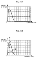
- Fig. 5A illustrates an example of the offset table held by the illumination-component offset table 27.
- the lateral axis represents an input luminance level
- the vertical axis represents the amount of the offset ofst1 (this is the same in Fig. 5B described below).
- the amount of offset ofst1 (vertical axis) is represented, for example by the following expression (1).
- Fig. 5B is a diagram for illustrating a relationship between the offset table held by the illumination-component offset table 27 and adjustment parameters.
- the input adjustment 1a (the arrow 1a in the figure) represents the amount of offset to be subtracted from the input luminance level to the offset table. That is to say, when the input is fixed, the input adjustment 1a is the amount to shifting the offset table in the right direction.
- the input adjustment 1b (the arrow 1b in the figure) represents the amount of gain by which the input luminance level to the offset table is multiplied. That is to say, when the input is fixed, the input adjustment 1b is the amount to increase or decrease the area width of the offset table, and corresponds to the adjustment of the luminance level range to be subjected processing.
- the gain 1c (the arrow 1c in the figure) represents the amount of a maximum gain by which the output luminance level from the offset table is multiplied. That is to say, the gain 1c is the amount to increase or decrease the vertical axis of the offset table, and is the value directly effective for the amount of boost of the processing.
- the adder 29 adds the input adjustment 2a supplied from the microcomputer 24 to the signal L supplied from the edge-detection function 21, and supplies the signal to the multiplier 30.
- the multiplier 30 multiplies the input adjustment 2b supplied from the microcomputer 24 to the signal L supplied from the adder 29, and supplies the signal to the illumination-component offset table 31.
- the illumination-component offset table 31 adjusts and holds the amount of offset and the amount of gain of the offset table, which determines the amount of boost of the luminance level of low range on the basis of the input adjustments 2a and 2b supplied from the adder 29 and the multiplier 30. Also, the illumination-component offset table 31 refers to the offset table held, and supplies the amount of offset ofst2 in accordance with the luminance level of the signal L supplied through the adder 29 and the multiplier 30 to the multiplier 32.
- the multiplier 32 multiplies the amount of offset ofst2 supplied from the illumination-component offset table 31 by the gain 2c supplied from the microcomputer 24, and supplies the product to the adder 33.
- Fig. 6A illustrates an example of the offset table held by the illumination-component offset table 31.
- the lateral axis represents an input luminance level
- the vertical axis represents the amount of the offset ofst2 (this is the same in Fig. 6B described below).
- the input luminance level (lateral axis) normalized into 8 bits is x in the offset table shown in Fig. 6A
- the amount of offset ofst2 (vertical axis) is represented, for example, by the following expression (2).
- Fig. 6B is a diagram for illustrating a relationship between the offset table held by the illumination-component offset table 31 and adjustment parameters.
- the input adjustment 2a (the arrow 2a in the figure) represents the amount of offset to be subtracted from the input luminance level to the offset table. That is to say, when the input is fixed, the input adjustment 2a is the amount to shift the offset table in the right direction.
- the input adjustment 2b (the arrow 2b in the figure) represents the amount of gain by which the input luminance level to the offset table is multiplied. That is to say, when the input is fixed, the input adjustment 2b is the amount to increase or decrease the area width of the offset table, and corresponds to the adjustment of the luminance level range to be subjected processing.
- the gain 2c (the arrow 2c in the figure) represents the amount of a maximum gain by which the output luminance level from the offset table is multiplied. That is to say, the gain 2c is the amount to increase or decrease the vertical axis of the offset table, and is the value directly effective for the amount of boost of the processing.
- the adder 33 adds the amount of offset ofst2, which is supplied from the multiplier 32 and determines the amount of boost of the low range luminance level whose maximum gain amount is adjusted, to the amount of offset ofst1, which is supplied from the multiplier 28 and determines the amount of boost of the ultra-low range luminance level whose maximum gain amount is adjusted, and supplies the obtained the amount of offset (illumination-component addition/subtraction remaining amount T (L)) to the adder 34.
- the adder 34 adds the illumination-component addition/subtraction remaining amount T (L) supplied from the adder 33 to the signal L (original illumination component) supplied from the LPF with an edge-detection function 21, and supplies the obtained gain-optimum illumination component (signal T (L)') to the adder 37.
- the adder 22 subtracts the signal L (illumination component) supplied from the LPF with an edge-detection function 21 from the luminance signal Y1 (original signal) input from the camera-signal processing section 12, and supplies the obtained texture component (signal R) to the adder 36.
- the reflectance-gain coefficient calculation section 35 refers to the reflectance-gain coefficient table, determines the area outside the ultra-low luminance and low luminance boost areas to be an adaptive area among boosted luminance signal, and supplies it to the aperture controller 23. Also, when the reflectance-gain coefficient calculation section 35 determines the adaptive area, the reflectance-gain coefficient calculation section 35 adjusts the amount of offset and the amount of gain in the reflectance-gain coefficient table on the basis of the input adjustment add and the output adjustment offset supplied from the microcomputer 24.
- Fig. 7A illustrates an example of the reflectance-gain coefficient table held by the reflectance-gain coefficient calculation section 35.
- the lateral axis represents an input luminance level
- the vertical axis represents the amount of the reflectance gain (this is the same in Fig. 7B described below).
- Fig. 7B is a diagram illustrating a relationship between the reflectance-gain coefficient table held by the reflectance-gain coefficient calculation section 35 and the adjustment parameters.
- the output adjustment offset (the arrow offset in the figure) represents the amount of gain by which the output luminance level from the reflectance-gain coefficient table is multiplied. That is to say, the output adjustment offset is the amount which increases the vertical axis of the reflectance-gain coefficient table.
- An adjustment parameter A (the arrow A in the figure) represents the parameter for determining the amount of a maximum gain of the aperture controller 23.
- the input adjustment add (the arrow add in the figure) represents the amount of the offset to be subtracted from the input luminance level of the reflectance-gain coefficient table. That is to say, when the input is fixed, the input adjustment add is the amount to shift the reflectance-gain coefficient table in the right direction.
- a limit level represents the maximum limit (amount of a maximum gain) set in order to prevent the aperture controller 23 from adding an extra aperture signal.
- the amount of aperture control apgain (vertical axis) is represented, for example by the following expression (3).
- A represents the amount of maximum gain of the aperture controller 23
- offset represents the amount of shifting in the upward direction in the reflectance-gain coefficient table
- add represents the amount of shifting in the right direction in the reflectance-gain coefficient table.
- the apgain' is output as the amount of aperture control apgain.
- the amount of aperture control apgain' is larger than limit level (the portion in which the value is greater than the limit level in the reflectance-gain coefficient table shown by a dotted line in Fig. 7B)
- the limit level is output as the amount of aperture control apgain.
- the aperture controller 23 performs the illumination-component level dependent aperture correction of the luminance signal Y1 input from the camera-signal processing section 12 so as to adapt to the outside of the boost area of ultra-low luminance and low luminance on the basis of the adaptive area determined by the reflectance-gain coefficient calculation section 35, and supplies the signal to the adder 36.
- the adder 36 adds the aperture-corrected luminance signal supplied from the aperture controller 23 to the signal R (the texture component produced by subtracting the illumination component from the original signal) supplied from the adder 22, and supplies the signal to the adder 37.
- the adder 37 adds the gain-optimum illumination component (the signal T (L)') supplied from the adder 34 to the texture component after the aperture correction supplied from the adder 36, and outputs the obtained luminance signal Y2 after the dynamic-range compression to the recording format processing section 14.
- the chroma-gain coefficient calculation section 38 refers to the chroma-gain coefficient table, determines the amount of gain, by which the chroma signal put on the low luminance level in particular is multiplied among the boosted luminance signals, and supplies it to the multiplier 39.
- Fig. 8A illustrates an example of the chroma-gain coefficient table held by the chroma-gain coefficient calculation section 38.
- the lateral axis represents an input luminance level
- the vertical axis represents the chroma gain
- an offset of 1 is put on the value of this vertical axis (this is the same in Fig. 8B described below).
- Fig. 8B is a diagram for illustrating a relationship between the coefficient table held by the chroma-gain coefficient calculation section 38 and adjustment parameter.
- the adjustment parameter B represents the parameter determining the amount of the maximum gain of the chroma-gain coefficient table (the arrow B in the figure).
- the amount of chroma gain cgain (vertical axis) is represented, for example by the following expression (4).
- B represents the amount of the maximum gain of the chroma-gain coefficient table.
- cgain B 54 ⁇ sin 1 10 ⁇ x , 0 ⁇ x ⁇ 17 B 54 ( 1 - cos 2 ⁇ 1 20 ⁇ x - 5.6 , 17 ⁇ x ⁇ 50 0 , 50 ⁇ x ⁇ 255
- the multiplier 39 multiplies the input chroma signal C1 by the amount of gain supplied from the chroma-gain coefficient calculation section 38, and supplies the signal to the HPF (Highpass Filter) 41 and the adder 43.
- HPF Highpass Filter
- the HPF 41 extracts the high-band component of the chroma signal supplied from the multiplier 39, and supplies it to the multiplier 42.
- a chroma-area determination section 40 selects an area to be subjected to the LPF on the chroma signal put on the luminance signal of the boosted area, and supplies it to the multiplier 42.
- Fig. 9 illustrates an example of the determination area used for the selection by the chroma-area determination section 40.
- the lateral axis represents an input luminance level
- the vertical axis represents the chroma gain.
- the determination area linearly changes from the boost area and non-boost area. By this means, the application of the LPF is adjusted.
- the chroma area carea vertical axis
- Expression 5 carea 1 , 0 ⁇ x ⁇ 75 - 1 25 ⁇ x + 4 , 75 ⁇ x ⁇ 100 0 , 100 ⁇ x ⁇ 255
- the multiplier 42 multiplies the chroma signal of high-band component supplied from the HPF 41 by the area, to which the LPF is applied, supplied from the chroma-area determination section 40, and supplies it to the adder 43.
- the adder 43 subtracts (That is to say, the LPF processing on the chroma signal of low-band level portion) the chroma signal of high-band component supplied from the multiplier 42 from the chroma signal supplied from the multiplier 39 in order to reduce chroma noise, and outputs the obtained chroma signal C2 after the dynamic-range compression to the recording-format processing section 14.
- the adder 25, the multiplier 26, the illumination-component offset table 27, and the multiplier 28 constitute the block which determines the amount of boost of the ultra-low band luminance level
- the adder 29, the multiplier 30, the illumination-component offset table 31, and the multiplier 32 constitute the block which determines the amount of boost of the low band luminance level.
- at least one block which determines the amount of boost of low luminance is necessary to be constituted, and that number may be one or may be two or more (plural).
- step S1 the LPF with an edge-detection function 21 detects (Fig. 3B) edges having a sharp change of pixel values of the luminance signal Y1 among the image data input by the camera-signal processing section 12, smooths the luminance signal Y1 while keeping the edges, and extracts an illumination component (signal L).
- the LPF with an edge-detection function 21 determines whether or not to smooth the luminance signal Y1 depending on whether or not the remarked pixel 51 is in the difference in level in the edge direction (the range B).
- the adder 22 subtracts the illumination component extracted by the processing of step S1 from the luminance signal Y1 (original signal) input by the camera-signal processing section 12, and separates the texture component (the signal R).
- step S3 the aperture controller 23 performs the illumination-component level dependent aperture correction of the luminance signal Y1 input from the camera-signal processing section 12 so as to adapt to the outside of the boost area of ultra-low luminance and low luminance on the basis of the adaptive area (Fig. 7B) determined by the reflectance-gain coefficient calculation section 35.
- step S4 the adder 33 adds the amount of offset ofst1 (Fig. 5B), which is supplied from the illumination-component offset table 27 through the multiplier 28 and determines the amount of boost of the ultra-low band luminance level with the amount of offset, the amount of gain, and the amount of the maximum gain being adjusted, and the amount of offset ofst2 (Fig.
- step S5 the adder 34 adds the illumination component extracted by the processing of step S1 and the illumination-component addition/subtraction remaining amount T (L) calculated by the processing of step S4, and obtains the gain-optimum illumination component (signal T (L)').
- step S6 the adder 37 adds the texture component having been subjected to the aperture correction by the processing of step S3 and the gain-optimum illumination component (signal T (L)') obtained by the processing of step S5, and obtains the output luminance signal Y2 after the dynamic-range compression.
- the output luminance signal Y2 after the dynamic-range compression obtained by the above processing is output to the recording-format processing section 14.
- step S21 the chroma-gain coefficient calculation section 38 calculates the amount of amplification (amount of gain) of the chroma signal C1 (Fig. 8B) from the illumination component of the luminance signal Y1 extracted by the processing of step S1 in Fig. 10 among the image data input from the camera-signal processing section 12.
- step S22 the chroma-area determination section 40 selects (Fig. 9) the noise-reduction area (That is to say, the area to which the LPF is applied) of the chroma signal C1 from the illumination component of the luminance signal Y1 extracted by the processing of step S1 in Fig. 10.
- step S23 the adder 43 reduces the chroma noise of the chroma signal of the low luminance level to which the gain is multiplied on the basis of the noise reduction area selected by the processing of step S22, and obtains the chroma signal C2 after the dynamic-range compression.
- the chroma signal C2 after the dynamic-range compression obtained by the above processing is output to the recording-format processing section 14.
- Fig. 12A illustrates an example of a histogram of the luminance component when the low luminance is simply subjected to the boost processing without considering the influence of the bit compression on the input image data in an 8-bit range changing from 0 to 255.
- Fig. 12B illustrates an example of a histogram of the luminance component when the compression processing is performed by the present invention on the input image data in an 8-bit range changing from 0 to 255.
- Fig. 12C illustrates an example of an accumulated histogram of Fig. 12A and Fig. 12B.
- H1 represents the accumulated histogram of Fig. 12A
- H2 represents the accumulated histogram of Fig. 12B.
- Fig. 13A illustrates an example of a histogram of the chroma component when the low luminance is simply subjected to the boost processing without considering the influence of the bit compression on the input image data in an 8-bit range changing from - 128 to 127.
- Fig. 13B illustrates an example of a histogram of the chroma component when the compression processing is performed by the present invention on the input image data in an 8-bit range changing from -128 to 127.
- the histogram in the level range from -50 to 50 is illustrated in Figs. 13A and 13B in order to show the details of the variation of the boosted level range.
- the histogram of the chroma component of the low level does not change under the influence of noise, and is comb-shaped (Fig. 13A).
- the chroma component is appropriately subjected to gain up corresponding to the boost area of the luminance component, and noise is reduced, and thus the histogram is smoothly changed from the center (low level area) to the outside (Fig. 13B).
- the low luminance portion also has grayscales potentially.
- a digital-image recording apparatus such as a digital video camera, etc.
- these series of processing can be executed by hardware, but can also be executed by software.
- the dynamic-range compression section 13 is implemented by a computer 100 as shown in Fig. 14.
- a CPU (Central Processing Unit) 101 executes various kinds of processing in accordance with the programs stored in a ROM 102 or the programs loaded into a RAM (Random Access Memory) 103 from a storage section 108. Also, the RAM 103 appropriately stores the data, etc., necessary for the CPU 101 to execute various kinds of processing.
- a CPU Central Processing Unit
- the CPU 101, the ROM 102, and the RAM 103 are mutually connected through a bus 104.
- An input/output interface 105 is also connected to the bus 104.
- An input section 106 including a keyboard, a mouse, etc., and an output section 107 including a display, etc., the storage section 108, and a communication section 109 are connected to the input/output interface 105.
- the communication section 109 performs communication processing through a network.
- a drive 110 is also connected to the input/output interface 105 as necessary, and a removable medium 111, such as a magnetic disk, an optical disc, a magneto-optical disc, or a semiconductor memory, etc., is attached appropriately.
- the computer programs read from there are installed in the storage section 108 as necessary.
- the program recording medium for recording the programs which are installed in a computer and is executable by the computer, not only includes, as shown in Fig. 14, a removable medium 111 including, such as a magnetic disk (including a flexible disk), an optical disc (including a CD-ROM (Compact Disc-Read Only Memory) and a DVD (Digital Versatile Disc)), a magneto-optical disc (including MD (Mini-Disc) (registered trademark)), or a semiconductor memory, etc.
- the program recording medium includes the ROM 103 storing the programs or a hard disk included in the storage section 108, etc., which are provided to the user in a built-in state in the main unit of the apparatus.
- the steps describing the programs to be stored in the recording medium include the processing to be performed in time series in accordance with the included sequence as a matter of course. Also, the steps include the processing which is not necessarily executed in time series, but is executed in parallel or individually.
- a system represents the entire apparatus including a plurality of apparatuses.
Landscapes
- Engineering & Computer Science (AREA)
- Multimedia (AREA)
- Signal Processing (AREA)
- Physics & Mathematics (AREA)
- General Physics & Mathematics (AREA)
- Theoretical Computer Science (AREA)
- Image Processing (AREA)
- Picture Signal Circuits (AREA)
- Processing Of Color Television Signals (AREA)
- Studio Devices (AREA)
Applications Claiming Priority (2)
| Application Number | Priority Date | Filing Date | Title |
|---|---|---|---|
| JP2004172212 | 2004-06-10 | ||
| PCT/JP2005/010350 WO2005122552A1 (fr) | 2004-06-10 | 2005-06-06 | Programme, méthode et dispositif de traitement d’image |
Publications (2)
| Publication Number | Publication Date |
|---|---|
| EP1755331A1 true EP1755331A1 (fr) | 2007-02-21 |
| EP1755331A4 EP1755331A4 (fr) | 2009-04-29 |
Family
ID=35503493
Family Applications (1)
| Application Number | Title | Priority Date | Filing Date |
|---|---|---|---|
| EP05751456A Withdrawn EP1755331A4 (fr) | 2004-06-10 | 2005-06-06 | Programme, méthode et dispositif de traitement d'image |
Country Status (6)
| Country | Link |
|---|---|
| US (1) | US20080284878A1 (fr) |
| EP (1) | EP1755331A4 (fr) |
| JP (1) | JP4497160B2 (fr) |
| KR (1) | KR20070026571A (fr) |
| CN (1) | CN1965570A (fr) |
| WO (1) | WO2005122552A1 (fr) |
Cited By (1)
| Publication number | Priority date | Publication date | Assignee | Title |
|---|---|---|---|---|
| WO2011108620A1 (fr) | 2010-03-02 | 2011-09-09 | Ricoh Company, Limited | Dispositif de traitement d'images et dispositif de capture d'images |
Families Citing this family (8)
| Publication number | Priority date | Publication date | Assignee | Title |
|---|---|---|---|---|
| JP4574457B2 (ja) * | 2005-06-08 | 2010-11-04 | キヤノン株式会社 | 画像処理装置およびその方法 |
| JP4524711B2 (ja) * | 2008-08-04 | 2010-08-18 | ソニー株式会社 | ビデオ信号処理装置、ビデオ信号処理方法、プログラム |
| US8766999B2 (en) * | 2010-05-20 | 2014-07-01 | Aptina Imaging Corporation | Systems and methods for local tone mapping of high dynamic range images |
| CN102095496B (zh) * | 2010-12-06 | 2012-09-05 | 宁波耀泰电器有限公司 | 一种测量动态照度分布的方法 |
| JP5488621B2 (ja) | 2012-01-11 | 2014-05-14 | 株式会社デンソー | 画像処理装置、画像処理方法、及びプログラム |
| US10368097B2 (en) * | 2014-01-07 | 2019-07-30 | Nokia Technologies Oy | Apparatus, a method and a computer program product for coding and decoding chroma components of texture pictures for sample prediction of depth pictures |
| US20160111063A1 (en) * | 2014-10-20 | 2016-04-21 | Trusight, Inc. | System and method for optimizing dynamic range compression image processing color |
| CN110278425A (zh) * | 2019-07-04 | 2019-09-24 | 潍坊学院 | 图像增强方法、装置、设备和存储介质 |
Citations (8)
| Publication number | Priority date | Publication date | Assignee | Title |
|---|---|---|---|---|
| US5606375A (en) * | 1994-08-31 | 1997-02-25 | Samsung Electronics Co. Ltd. | Method for enhancing detail in color signals and circuitry for implementing that method in color video equipment |
| US5621480A (en) * | 1993-04-19 | 1997-04-15 | Mitsubishi Denki Kabushiki Kaisha | Image quality correction circuit and method based on color density |
| US5848181A (en) * | 1995-07-26 | 1998-12-08 | Sony Corporation | Image processing method, image processing apparatus, noise removing method, and noise removing apparatus |
| US20020047911A1 (en) * | 2000-03-23 | 2002-04-25 | Takashi Tsuchiya | Image processing circuit and method for processing image |
| US20030016306A1 (en) * | 2001-06-20 | 2003-01-23 | Masami Ogata | Method and apparatus for processing image |
| US6611296B1 (en) * | 1999-08-02 | 2003-08-26 | Koninklijke Philips Electronics N.V. | Video signal enhancement |
| US6694051B1 (en) * | 1998-06-24 | 2004-02-17 | Canon Kabushiki Kaisha | Image processing method, image processing apparatus and recording medium |
| US6768514B1 (en) * | 1998-11-18 | 2004-07-27 | Sony Corporation | Image processing apparatus and image processing method |
Family Cites Families (10)
| Publication number | Priority date | Publication date | Assignee | Title |
|---|---|---|---|---|
| KR0176601B1 (ko) * | 1996-05-21 | 1999-05-01 | 김광호 | 저역 필터링과 히스토그램 등화를 이용한 화질개선 방법 및 그 회로 |
| DE19637613C2 (de) * | 1996-09-16 | 2000-02-24 | Heidelberger Druckmasch Ag | Druckmaschine zum Erzeugen eines Bildes mittels Tonpartikeln |
| JP4227222B2 (ja) * | 1998-07-14 | 2009-02-18 | キヤノン株式会社 | 信号処理装置、信号処理方法及び記憶媒体 |
| JP2001024907A (ja) * | 1999-07-06 | 2001-01-26 | Matsushita Electric Ind Co Ltd | 撮像装置 |
| US6724943B2 (en) * | 2000-02-07 | 2004-04-20 | Sony Corporation | Device and method for image processing |
| JP4415236B2 (ja) * | 2000-02-07 | 2010-02-17 | ソニー株式会社 | 画像処理装置及び画像処理方法 |
| WO2002102086A2 (fr) * | 2001-06-12 | 2002-12-19 | Miranda Technologies Inc. | Appareil et procede pour la reduction spatiale, adaptative a base de segmentation, de nuisances pour des signaux d'image codes |
| JP2003101815A (ja) * | 2001-09-26 | 2003-04-04 | Fuji Photo Film Co Ltd | 信号処理装置及び信号処理方法 |
| JP3999091B2 (ja) * | 2002-09-25 | 2007-10-31 | 富士フイルム株式会社 | 画像補正処理装置及びプログラム |
| US7139036B2 (en) * | 2003-01-31 | 2006-11-21 | Samsung Electronics Co., Ltd. | Method and apparatus for image detail enhancement using filter bank |
-
2005
- 2005-06-06 WO PCT/JP2005/010350 patent/WO2005122552A1/fr not_active Application Discontinuation
- 2005-06-06 CN CNA2005800190560A patent/CN1965570A/zh active Pending
- 2005-06-06 JP JP2006514495A patent/JP4497160B2/ja not_active Expired - Fee Related
- 2005-06-06 EP EP05751456A patent/EP1755331A4/fr not_active Withdrawn
- 2005-06-06 KR KR1020067025938A patent/KR20070026571A/ko not_active Application Discontinuation
- 2005-06-06 US US11/629,152 patent/US20080284878A1/en not_active Abandoned
Patent Citations (8)
| Publication number | Priority date | Publication date | Assignee | Title |
|---|---|---|---|---|
| US5621480A (en) * | 1993-04-19 | 1997-04-15 | Mitsubishi Denki Kabushiki Kaisha | Image quality correction circuit and method based on color density |
| US5606375A (en) * | 1994-08-31 | 1997-02-25 | Samsung Electronics Co. Ltd. | Method for enhancing detail in color signals and circuitry for implementing that method in color video equipment |
| US5848181A (en) * | 1995-07-26 | 1998-12-08 | Sony Corporation | Image processing method, image processing apparatus, noise removing method, and noise removing apparatus |
| US6694051B1 (en) * | 1998-06-24 | 2004-02-17 | Canon Kabushiki Kaisha | Image processing method, image processing apparatus and recording medium |
| US6768514B1 (en) * | 1998-11-18 | 2004-07-27 | Sony Corporation | Image processing apparatus and image processing method |
| US6611296B1 (en) * | 1999-08-02 | 2003-08-26 | Koninklijke Philips Electronics N.V. | Video signal enhancement |
| US20020047911A1 (en) * | 2000-03-23 | 2002-04-25 | Takashi Tsuchiya | Image processing circuit and method for processing image |
| US20030016306A1 (en) * | 2001-06-20 | 2003-01-23 | Masami Ogata | Method and apparatus for processing image |
Non-Patent Citations (1)
| Title |
|---|
| See also references of WO2005122552A1 * |
Cited By (6)
| Publication number | Priority date | Publication date | Assignee | Title |
|---|---|---|---|---|
| WO2011108620A1 (fr) | 2010-03-02 | 2011-09-09 | Ricoh Company, Limited | Dispositif de traitement d'images et dispositif de capture d'images |
| EP2543017A1 (fr) * | 2010-03-02 | 2013-01-09 | Ricoh Company, Limited | Dispositif de traitement d'images et dispositif de capture d'images |
| EP2543017A4 (fr) * | 2010-03-02 | 2013-01-09 | Ricoh Co Ltd | Dispositif de traitement d'images et dispositif de capture d'images |
| CN102893305A (zh) * | 2010-03-02 | 2013-01-23 | 株式会社理光 | 图像处理设备和图像获取设备 |
| US8982243B2 (en) | 2010-03-02 | 2015-03-17 | Ricoh Company, Limited | Image processing device and image capturing device |
| CN102893305B (zh) * | 2010-03-02 | 2015-12-16 | 株式会社理光 | 图像处理设备和图像获取设备 |
Also Published As
| Publication number | Publication date |
|---|---|
| JP4497160B2 (ja) | 2010-07-07 |
| US20080284878A1 (en) | 2008-11-20 |
| CN1965570A (zh) | 2007-05-16 |
| EP1755331A4 (fr) | 2009-04-29 |
| WO2005122552A1 (fr) | 2005-12-22 |
| JPWO2005122552A1 (ja) | 2008-04-10 |
| KR20070026571A (ko) | 2007-03-08 |
Similar Documents
| Publication | Publication Date | Title |
|---|---|---|
| EP1755331A1 (fr) | Programme, méthode et dispositif de traitement d'image | |
| US8339468B2 (en) | Image processing device, image processing method, and image pickup apparatus | |
| US6724943B2 (en) | Device and method for image processing | |
| US7920183B2 (en) | Image processing device and digital camera | |
| EP2216988B1 (fr) | Dispositif de traitement d'image et procédé, programme et support d'enregistrement | |
| US8144985B2 (en) | Method of high dynamic range compression with detail preservation and noise constraints | |
| JP5157753B2 (ja) | 画像処理装置、画像処理方法、画像処理プログラム | |
| JP4894595B2 (ja) | 画像処理装置および方法、並びに、プログラム | |
| JP4869653B2 (ja) | 画像処理装置 | |
| US20120301050A1 (en) | Image processing apparatus and method | |
| US20080187235A1 (en) | Image processing apparatus, imaging apparatus, imaging processing method, and computer program | |
| US8526736B2 (en) | Image processing apparatus for correcting luminance and method thereof | |
| US9712797B2 (en) | Image processing apparatus, image pickup apparatus, image processing method, and non-transitory computer-readable medium | |
| US7587089B2 (en) | Method and apparatus for image processing | |
| JP3184309B2 (ja) | 階調補正回路及び撮像装置 | |
| JP5183440B2 (ja) | 階調補正装置および撮像装置 | |
| US8693799B2 (en) | Image processing apparatus for emphasizing details of an image and related apparatus and methods | |
| JP5295854B2 (ja) | 画像処理装置及び画像処理プログラム | |
| JP5142833B2 (ja) | 画像処理装置及び画像処理方法 | |
| JP4479600B2 (ja) | 画像処理装置および方法、並びにプログラム | |
| EP2410731B1 (fr) | Appareil de correction des bordures, procédé de correction des bordures, programme et support de stockage | |
| US7773824B2 (en) | Signal processing device and method, recording medium, and program | |
| JPH05167889A (ja) | 画像信号処理装置 | |
| JP2006279812A (ja) | 輝度信号処理装置 | |
| JP4304609B2 (ja) | 信号処理装置および方法、記録媒体、並びにプログラム |
Legal Events
| Date | Code | Title | Description |
|---|---|---|---|
| PUAI | Public reference made under article 153(3) epc to a published international application that has entered the european phase |
Free format text: ORIGINAL CODE: 0009012 |
|
| 17P | Request for examination filed |
Effective date: 20061128 |
|
| AK | Designated contracting states |
Kind code of ref document: A1 Designated state(s): AT BE BG CH CY CZ DE DK EE ES FI FR GB GR HU IE IS IT LI LT LU MC NL PL PT RO SE SI SK TR |
|
| DAX | Request for extension of the european patent (deleted) | ||
| A4 | Supplementary search report drawn up and despatched |
Effective date: 20090327 |
|
| STAA | Information on the status of an ep patent application or granted ep patent |
Free format text: STATUS: THE APPLICATION HAS BEEN WITHDRAWN |
|
| 18W | Application withdrawn |
Effective date: 20090818 |