EP1754894A2 - Press fit connector and manufacturing method thereof - Google Patents
Press fit connector and manufacturing method thereof Download PDFInfo
- Publication number
- EP1754894A2 EP1754894A2 EP06025191A EP06025191A EP1754894A2 EP 1754894 A2 EP1754894 A2 EP 1754894A2 EP 06025191 A EP06025191 A EP 06025191A EP 06025191 A EP06025191 A EP 06025191A EP 1754894 A2 EP1754894 A2 EP 1754894A2
- Authority
- EP
- European Patent Office
- Prior art keywords
- press
- fit
- outer diameter
- connection element
- head
- Prior art date
- Legal status (The legal status is an assumption and is not a legal conclusion. Google has not performed a legal analysis and makes no representation as to the accuracy of the status listed.)
- Granted
Links
- 238000004519 manufacturing process Methods 0.000 title claims description 15
- 238000000034 method Methods 0.000 claims abstract 3
- 230000000630 rising effect Effects 0.000 claims description 12
- 230000004323 axial length Effects 0.000 claims description 4
- 238000005096 rolling process Methods 0.000 claims description 4
- 238000005520 cutting process Methods 0.000 claims description 3
- 230000007423 decrease Effects 0.000 claims description 3
- 238000013461 design Methods 0.000 description 6
- 239000000463 material Substances 0.000 description 6
- 238000005553 drilling Methods 0.000 description 5
- 230000000694 effects Effects 0.000 description 4
- 238000003780 insertion Methods 0.000 description 3
- 230000037431 insertion Effects 0.000 description 3
- 238000009434 installation Methods 0.000 description 3
- 238000012545 processing Methods 0.000 description 3
- 230000000153 supplemental effect Effects 0.000 description 3
- 230000015572 biosynthetic process Effects 0.000 description 2
- 238000003825 pressing Methods 0.000 description 2
- 238000010008 shearing Methods 0.000 description 2
- 238000012549 training Methods 0.000 description 2
- 230000007704 transition Effects 0.000 description 2
- NPPQSCRMBWNHMW-UHFFFAOYSA-N Meprobamate Chemical compound NC(=O)OCC(C)(CCC)COC(N)=O NPPQSCRMBWNHMW-UHFFFAOYSA-N 0.000 description 1
- 229910000831 Steel Inorganic materials 0.000 description 1
- XAGFODPZIPBFFR-UHFFFAOYSA-N aluminium Chemical compound [Al] XAGFODPZIPBFFR-UHFFFAOYSA-N 0.000 description 1
- 229910052782 aluminium Inorganic materials 0.000 description 1
- 238000013459 approach Methods 0.000 description 1
- 230000000295 complement effect Effects 0.000 description 1
- 238000009826 distribution Methods 0.000 description 1
- 238000005516 engineering process Methods 0.000 description 1
- 238000001125 extrusion Methods 0.000 description 1
- CPJSUEIXXCENMM-UHFFFAOYSA-N phenacetin Chemical compound CCOC1=CC=C(NC(C)=O)C=C1 CPJSUEIXXCENMM-UHFFFAOYSA-N 0.000 description 1
- 239000010959 steel Substances 0.000 description 1
Images


Classifications
-
- F—MECHANICAL ENGINEERING; LIGHTING; HEATING; WEAPONS; BLASTING
- F16—ENGINEERING ELEMENTS AND UNITS; GENERAL MEASURES FOR PRODUCING AND MAINTAINING EFFECTIVE FUNCTIONING OF MACHINES OR INSTALLATIONS; THERMAL INSULATION IN GENERAL
- F16B—DEVICES FOR FASTENING OR SECURING CONSTRUCTIONAL ELEMENTS OR MACHINE PARTS TOGETHER, e.g. NAILS, BOLTS, CIRCLIPS, CLAMPS, CLIPS OR WEDGES; JOINTS OR JOINTING
- F16B35/00—Screw-bolts; Stay-bolts; Screw-threaded studs; Screws; Set screws
- F16B35/04—Screw-bolts; Stay-bolts; Screw-threaded studs; Screws; Set screws with specially-shaped head or shaft in order to fix the bolt on or in an object
- F16B35/041—Specially-shaped shafts
- F16B35/048—Specially-shaped necks
-
- F—MECHANICAL ENGINEERING; LIGHTING; HEATING; WEAPONS; BLASTING
- F16—ENGINEERING ELEMENTS AND UNITS; GENERAL MEASURES FOR PRODUCING AND MAINTAINING EFFECTIVE FUNCTIONING OF MACHINES OR INSTALLATIONS; THERMAL INSULATION IN GENERAL
- F16B—DEVICES FOR FASTENING OR SECURING CONSTRUCTIONAL ELEMENTS OR MACHINE PARTS TOGETHER, e.g. NAILS, BOLTS, CIRCLIPS, CLAMPS, CLIPS OR WEDGES; JOINTS OR JOINTING
- F16B4/00—Shrinkage connections, e.g. assembled with the parts at different temperature; Force fits; Non-releasable friction-grip fastenings
- F16B4/004—Press fits, force fits, interference fits, i.e. fits without heat or chemical treatment
Definitions
- the invention relates to a press-fit connecting element having a shaft, a head adjoining the shaft and a press-fit section provided on the shaft with a helical profile with an inlet region.
- Such press-fit connection elements serve in combination with a corresponding bore arranged in a component for producing a press-fit connection. Irrespective of the tolerance pairing of the press-fit connection present in the concrete individual case, the outer diameter of the press-fit section always has a certain excess compared to the inner diameter of the bore, from which the desired secure frictional connection results.
- a Presspassharmselement in particular a wheel bolt, is from the DE 43 18 494 C1 known.
- the press-fit connection element has a shank, a head adjoining the shank and a press-fit section provided with a multi-turn helical profile on the shank.
- the spiral profile has, like every thread, an inlet area and an outlet area.
- the helical profile has several threads with a corresponding pitch.
- the known Presspassitatiselement is always used in conjunction with a reworked hole in the component. Theoretically, it would be possible to dispense with a reworking of the bore or the bore could have a relatively large tolerance for other reasons. Such a non-reworked bore then has a tolerance in the range of IT 10 to IT 12. This means that the difference of the amounts of the inner diameter of the largest hole produced within the tolerance field and the smallest hole produced within the tolerance field is relatively large. Now, if the known press-fit connecting element would be pressed into such a bore in the component with a comparatively large inner diameter, the overlap and the resulting friction was insufficient to ensure the interference fit securely. There is a risk that the press-fit connection element unintentionally releases from the bore.
- the invention has for its object to provide a press-fit connection element, which can be pressed with good security effect and reusability in a machined with a relatively large tolerance bore.
- the object of the invention is achieved by a press-fit connection element having the features of independent claim 1 and by a method for producing a press-fit connection element having the features of independent claim 12.
- the axial knurled wheel bolt has a knurled press-fit section with axially extending knurls, ie with a multiplicity of adjacent ribs and grooves extending parallel to each other.
- a connecting element for connecting two components under prestressing is known from US 3,418,012 known.
- the known connecting element has a tapered swaging portion with substantially axially extending channels and ribs. In contrast to a thread or helical profile, the channels and ribs are either exactly axial, ie with a pitch of 90 °, or arranged with a slightly smaller pitch.
- the connecting element is introduced into two mutually aligned bores in the two components arranged one above the other.
- the bores were previously introduced together in such a way in the two components, that the diameter of the cylindrical bore is approximately between 25 microns [1/1000 inch] to 30 microns [12/1000 inch] smaller than the immediately below the head arranged maximum diameter of the Shaft of the connecting element.
- the connecting element is introduced under rotation into the bore. This results in an elastic-plastic deformation of the initially cylindrical bore, which also receives a conical design due to the frusto-conical geometry of the shaft of the connecting element.
- Press-fit fasteners with a shank, a head adjoining the shank and a press-fit portion with a knurl provided on the shank are known from US Pat GB 891,807 and the US 3,252,495 known.
- the knurl consists of spaced, parallel, around the screw axis encircling Rändelaboughen.
- the knurling sections have knurling elements which extend substantially in the direction of the screw axis.
- the knurling elements are inclined at an angle of about 10 ° with respect to the screw axis to ensure rotation of the press-fit connection element upon insertion into a corresponding bore.
- the new press-fit connection element has a shaft, a head adjoining the shaft and a press-fit section provided on the shaft with a helical profile with an inlet region.
- the press-fit portion has, in addition to the lead-in area, a rise area in which the outer diameter of the press-fit portion increases toward the head up to a maximum outer diameter with the maximum outer diameter of the rise area of the press-fit portion spaced from the head.
- press-fit connections - for example between wheel bolts and the hub of a car or truck - can be made safely and reliably, even with relatively large tolerances of the bores in the hub.
- the press-fit connection element according to the invention is pressed into a bore with a comparatively small inner diameter, then in the rise region of the press-fit section -d. H. a region with an outer diameter increasing toward the head, but smaller than the maximum outer diameter of the press-fit portion, to no or at least lower elastic-plastic deformations than in the region of the maximum outer diameter of the press-fit portion.
- the occurrence of undesirable stresses in the component and the press-fit connector is reduced, and the press-fit connector and corresponding bore member can be reused after the first release of the press-fit connection to reestablish a secure press-fit connection.
- the riser portion of the press-fit portion terminates spaced from the head of the connector to prevent the occurrence of undesirable near-head stresses and possible concomitant jackpot losses.
- the rise area of the press-fit portion is to be distinguished from the run-in area present in each helical profile.
- a helix is a continuous recess which winds around the screw axis and has projections provided between the individual turns of the depression and which likewise extends helically around the helix axis.
- manufacturing technology due to a slight increase in the outer diameter. In conventional helical profiles according to the prior art, however, this increase in the outer diameter does not continue.
- the known press-fit section has a constant core diameter and a constant outside diameter over the axial length.
- the press-fit section according to the invention or the spiral profile arranged therein has at least also outside the inlet area the rise area with an increasing outside diameter. It is preferred that the core diameter of the helical profile is constant.
- a plurality of further regions may be provided in the press-fit section, wherein the regions z. B. have different slopes with respect to their outer diameter or may be interconnected by cylindrical complementary areas.
- all of these different embodiments have in common that there is at least one rising region in which the outer diameter of the press-fitting section increases until the maximum outer diameter is reached.
- the rise range ends at this point. If this is followed by a cylindrical area with the maximum outer diameter, then this is referred to as supplementary area. Depending on further embodiment, this supplementary area can then extend over a more or less large axial portion of the press-fit section.
- the press-fitting portion may have, in addition to the rising portion, at least one descent region in which the outer diameter of the press-fitting portion decreases toward the head.
- the descent region can be formed in particular mirror-symmetrically to the rise area, which in particular brings manufacturing advantages with it, because thus the emergence of resultant axial forces is avoided in particular the rolling on the press-fit connection element.
- the material stress is reduced in the critical edge zones of the component.
- the press-fit portion may have a barrel-like shape.
- a barrel-shaped form can be produced particularly well by rolling.
- the adjacent points in both axial directions due to the relatively small pitch and deformations encountered when inserting the press-fit connection member into a bore, are also virtually the maximum outside diameter. This ensures that a sufficient axial range is available for the desired coverage.
- the press-fit section can be designed such that the entire helical profile is used to produce a press-fit connection.
- a part of the helical profile has a shortage over the inner diameter of the bore - d.
- a clearance fit or transitional fit forms - and only one next in the direction of the increasing outer diameter following part of the helical profile has the necessary excess to provide the desired interference fit.
- a cylindrical supplementary area which has the maximum outer diameter.
- a cylindrical supplementary area can also be provided in addition to the rise area.
- This supplemental area then has a certain axial extent, so that the rise area ends at a distance from the head of the connecting element.
- the cylindrical supplemental area also terminates spaced from the head of the connector to prevent the occurrence of undesirable stresses. In this way it is ensured that the area of the maximum diameter - d. H. its axial extent - is sufficient to achieve the desired tight interference fit.
- the cylindrical supplementary portion may be provided between the rising portion and the descending portion of the press-fitting portion.
- the helical profile can be designed more smoothly and in particular at least six.
- the pitch angle of the helical profile can in particular be between 5 ° and 30 °. Depending on the configuration of the helical profile and the Presspassabitess also significantly more courses may be present, for. B. up to 18 gears.
- the pitch angle is preferably between 9 ° and 11 °.
- the pitch angle is to be understood as the angle between an imaginary line running perpendicular to the axis of the connecting element and the helices.
- the selection of the pitch angle in a range of between 5 ° and 30 ° - preferably between 9 ° and 11 ° - has the advantage that displaced by the outer surfaces of the coil displaced material of the inner surface of the bore is less elastic-plastically deformed, as this is the case at larger and smaller angles.
- a threaded portion may be provided with a thread having a pitch diameter.
- the helical profile may have a core diameter that is greater than or equal to the pitch diameter of the thread. Due to this design, the helical profile has a stress cross section which is preferably about 15% or more greater than the stress cross section of the thread.
- the spiral profile has a significantly lower profile height than a normal thread.
- a centering whose outer diameter is greater than the outer diameter of the thread and preferably smaller than the minimum outer diameter of the helical profile in the inlet region.
- the centering portion serves to facilitate the axial insertion of the press-fit connection element into the corresponding bore in the component.
- this centering has a frusto-conical shape, whereby the desired centering effect is achieved safely when inserting the centering in the bore of the component.
- the centering approach preferably has no profile and may have an outer diameter which corresponds approximately to the pitch diameter of the thread.
- the centering portion may have an axial length corresponding to between 10% and 50%, preferably 25%, of the maximum outer diameter of the press-fit portion. This dimensioning ensures that an undesirable oblique insertion of the press-fit connection element into the bore is avoided.
- the press-fit connection element may be a wheel bolt.
- wheel bolts are used to connect the hub of a car or truck with the rim of a wheel.
- the wheel bolt is connected by means of the press-fit connection with the hub.
- a nut is screwed onto the threaded end of the wheel bolt arranged at the end.
- the press-fit connection element according to the invention can also be used for the production of all other press-fit connections.
- the coverage of the interference fit is a minimum of about 0.25% and a maximum of about 1.1%, resulting in a coverage window of about 0.85%.
- DE 43 18 494 C1 Page 4, lines 36-38 were previously known in spiral profiles overlaps in the range of 0.3 to 0.7%. This results in a coverage window of 0.4%. With the A new overlay window can be used to reduce the cost of producing the new press-fit connection.
- the new method of manufacturing a press-fit fastener having a shank and a head includes the steps of cold-forming a press-fit portion provided on the shank of the press-fit fastener to produce a cylindrical helical profile, and cutting the helix profile to produce a rise area in which the outer diameter of the press-fit portion is oriented in the direction up to a maximum outer diameter increases such that the maximum outer diameter of the rising portion of the press-fitting portion is spaced from the head.
- Non-cutting calibration can be done in particular by rolling or by shafts. This can be advantageous to generate a high areal proportion of the helical profile.
- the helical profile preferably has a surface carrying portion of at least about 30%.
- the surface carrying portion may be between about 30% and 80%, preferably between 40% and 70%, preferably about 50-60%.
- In the surface support portion is the area at the outer diameter of the helical profile, which has after completion of the press-fitting of the press-fit portion in the corresponding bore contact with the inner wall of the bore.
- the percentage indication of the areal component is based on the cylindrical surface area of the bore, it being assumed that the bore and the press-fit portion coincide in their axial length.
- the core diameter of the helical profile remains approximately constant during the calibration of the helical profile in the rise area.
- the outer diameter of the helical profile is preferably calibrated so precisely that it lies in a very accurate tolerance range of IT 7. As a result, the requirements for the tolerance of the corresponding hole in the component are reduced.
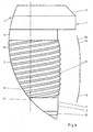
- FIG. 1 shows a first embodiment of the new press-fit connection element 1.
- the press-fit connection element 1 has a shaft 2 and a head 3 adjoining the shaft 2.
- a press-fit section 4 with a multi-turn helical profile 5 is also provided on the shaft 2.
- the exemplary spiral profile 5 shown in Fig. 1 is a six-speed helical profile 5.
- the helical profile 5 could also have more gears - for example, up to 18 gears.
- the spiral profile has an inlet region 6 and an outlet region 7.
- the press-fit section 4 has, in addition to the inlet region 6, a rise region 8 in which the outside diameter of the press-fit section 4 increases in the direction of the head 3 up to a maximum outside diameter.
- the slope of the rise area 8 is greatly exaggerated for reasons of clarity. In reality, the difference between the maximum outer diameter of the helical profile 5 and the minimum outer diameter of the helical profile 5 is much smaller. It is z. B. in the order of 5/100 mm. By contrast, the core diameter of the helical profile 5 is approximately constant over the length of the helical profile 5.
- the maximum outer diameter of the rising region 8 of the press-fit section 4 is arranged at a distance from the head 3. Between the outlet region 7 of the helical profile 5 and the underside of the head 3, a distance region 9 is provided. In addition to the rising portion 8, the press-fitting portion 4 has a descent portion 10 in which the outer diameter of the press-fitting portion 4 decreases toward the head 3.
- the Presspassabites 4 has a total of a slightly barrel-shaped or spherical shape.
- a centering section 11 is provided following the inlet region 6 of the helical profile 5 in the direction away from the head 3.
- the centering section 11 has a cylindrical part 12.
- Another frustoconical part 13 adjoins the centering section 11. By definition, it is not part of the centering section 11.
- the initial diameter of the centering section 11 is smaller than the minimum outer diameter of the helical profile 5 in the inlet region 6.
- a threaded section 14 with a thread 15 is arranged. It can be a metric or another thread.
- the diameter of the frusto-conical portion 13 of the centering portion 11 increases to a value larger than the value of the outer diameter of the thread 15 of the threaded portion 14.
- the press-fit connection element 1 shows a position of the new press-fit connection element 1 shortly before the production of the desired press-fit connection with a component 16.
- the component 16 may in particular be the hub of a car or truck.
- the press-fit connection element 1 is accordingly a wheel bolt 18.
- the component 16 has a bore 19, which extends as a through-bore through the component 16.
- the bore 19 is preferably a mere by drilling - d. H. without subsequent further processing - produced bore with a tolerance of IT 10 to IT 12.
- the press-fit connection element 1 is pressed by a pure axial force into the corresponding bore 19 of the component 16.
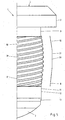
- Fig. 2 shows a second embodiment of the press-fit connection element 1 according to the invention, wherein in this embodiment, only the head 3 has a slightly different design.
- FIGS. 1 and 2 Details of the helical profile 5 according to FIGS. 1 and 2 are shown in FIG .
- Fig. 3 in particular the (graphically exaggerated) barrel-shaped design of the helical profile 5 of the Presspassabitess 4 is clearly visible.
- This training is additionally represented symbolically by a line 20.
- FIG. 4 shows a further embodiment of the helical profile 5, it being apparent from the line 20 that a rise area 8, a descent area 10 and a cylindrical supplementary area 21 are provided, the cylindrical supplementary area 21 extending between the mirror-symmetrical areas 8, 10 , The transition between the areas 8, 10 on the one hand and 21 on the other hand is provided in this embodiment with a radius.
- the helical profile 5 may also have a linear or pointed course instead of the radius described above.
- FIG. 7 illustrates a similar embodiment to FIG. 6, again using a radius.
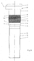
- FIG. 8 shows the press-fit connection element 1 in its position mounted in the component 16. It can be seen that, at least in the area of the maximum diameter of the press-fit section 4 or of the helical profile 5, such an overlap exists between the outer diameter of the helical profile 5 and the inner diameter of the bore 19 that there is a secure interference fit.
- the representations of the rise area 9 and also of the descent area 10 are greatly exaggerated for better understanding, however.
- a clearance fit results at the ends of the helical profile 5.
- the helical profile 5 can also be designed so that in the entire region of the helical profile 5 is present a press fit.
- the degree of overlap at the beginning of the rise area 8 is lower, so that overall when pressing the new press-fit connection element 1 into the bore 19 lower elastic-plastic deformations occur than in the prior art.
- the range of maximum overlap, or maximum diameter is chosen to be large enough to achieve the desired secure interference fit for all tolerance pairings.
- FIG. 9 shows a section of the connection point between the head 3 of the press-fit connection element 1 and the component 16.
- a circumferential groove 22 provided on the underside of the head 3, it is possible to dispense with the attachment of a chamfer to the component 16.
- the groove 22 ensures that the head 3 contacts the upper surface of the component 16 with its lower bearing surface and that no large laying force losses due to burrs or the like occur.
- FIG. 10 shows the formation of the head 3 with a stop 23.
- the stop 23 is used in the mounted position to prevent unwanted rotation of the connecting element 1 in the bore 19.
- Fig. 10 shows the six-start training of the helical profile 5.
- the press-fit connection element shows a further embodiment of the press-fit connection element, in which case the press-fit section 4 and the helical profile 5 are even further spaced from the head 3 are arranged. Accordingly, the distance region 9 has a greater axial extent.
- Fig. 12 illustrates the pitch angle ⁇ of the helical profile 5.
- the pitch angle ⁇ is in a range of 10 °.
- FIG. 13 shows two concrete installation situations of the new press-fit connection element 1, the first installation situation being shown above the symmetry line and the second installation situation below the symmetry line.
- the Presspassitatiselements 1 is in the form of a wheel bolt 18 and fixedly connected to the hub 17 of a car or truck.
- a rim 24 is fixed to the hub 17 by means of the press-fit connection member 1 and a nut 25.
- the rim 24 shown above the line of symmetry has a relatively large wall thickness. For example, this is an aluminum rim.
- the rim 24 shown below the symmetry line has a relatively small wall thickness. For example, this is a steel rim.
Landscapes
- Engineering & Computer Science (AREA)
- General Engineering & Computer Science (AREA)
- Mechanical Engineering (AREA)
- Automatic Assembly (AREA)
- Connection Of Plates (AREA)
- Forging (AREA)
- Mutual Connection Of Rods And Tubes (AREA)
- Multi-Conductor Connections (AREA)
- Connector Housings Or Holding Contact Members (AREA)
- Connections Arranged To Contact A Plurality Of Conductors (AREA)
- Coupling Device And Connection With Printed Circuit (AREA)
Abstract
Description
Die Erfindung betrifft ein Presspassverbindungselement mit einem Schaft, einem an den Schaft anschließenden Kopf und einem am Schaft vorgesehenen Presspassabschnitt mit einem Wendelprofil mit einem Einlaufbereich.The invention relates to a press-fit connecting element having a shaft, a head adjoining the shaft and a press-fit section provided on the shaft with a helical profile with an inlet region.
Derartige Presspassverbindungselemente dienen in Kombination mit einer in einem Bauteil angeordneten korrespondierenden Bohrung zum Herstellen einer Presspassverbindung. Unabhängig von der im konkreten Einzelfall vorliegenden Toleranzpaarung der Presspassverbindung besitzt der Außendurchmesser des Presspassabschnitts im Vergleich zum Innendurchmesser der Bohrung stets ein gewisses Übermaß, aus dem sich der gewünschte sichere Reibschluss ergibt.Such press-fit connection elements serve in combination with a corresponding bore arranged in a component for producing a press-fit connection. Irrespective of the tolerance pairing of the press-fit connection present in the concrete individual case, the outer diameter of the press-fit section always has a certain excess compared to the inner diameter of the bore, from which the desired secure frictional connection results.
Ein Presspassverbindungselement, insbesondere ein Radbolzen, ist aus der
Das bekannte Presspassverbindungselement wird stets in Verbindung mit einer nachbearbeiteten Bohrung im Bauteil eingesetzt. Theoretisch könnte auf eine Nachbearbeitung der Bohrung verzichtet werden oder die Bohrung könnte aus anderen Gründen eine relativ große Toleranz besitzen. Eine derartige nicht nachbearbeitete Bohrung besitzt dann eine Toleranz im Bereich von IT 10 bis IT 12. Dies bedeutet, dass die Differenz der Beträge der Innendurchmesser der größten innerhalb des Toleranzfelds gefertigten Bohrung und der kleinsten innerhalb des Toleranzfelds gefertigten Bohrung relativ groß ist. Wenn nun das bekannte Presspassverbindungselement in eine solche Bohrung im Bauteil mit einem vergleichsweise großen Innendurchmesser eingepresst würde, reichte die Überdeckung und die daraus resultierende Reibung nicht aus, um den Presspasssitz sicher zu gewährleisten. Es bestünde die Gefahr, dass sich das Presspassverbindungselement ungewollt aus der Bohrung löst. Wenn hingegen das bekannte Presspassverbindungselement in eine solche Bohrung mit einem vergleichsweise kleinen Innendurchmesser eingepresst würde, käme es notwendigerweise zu starken elastisch-plastischen Verformungen sowohl des Presspassabschnitts des Presspassverbindungselements als auch der Bohrung des Bauteils. Dadurch entstehen unerwünschte Spannungen im Bauteil und im Presspassverbindungselement Das Presspassverbindungselement und/oder das mit der korrespondierenden Bohrung versehene Bauteil können nach dem erstmaligen Lösen der Presspassverbindung praktisch nicht zur erneuten Herstellung einer sicheren Presspassverbindung wiederverwendet werden.The known Presspassverbindungselement is always used in conjunction with a reworked hole in the component. Theoretically, it would be possible to dispense with a reworking of the bore or the bore could have a relatively large tolerance for other reasons. Such a non-reworked bore then has a tolerance in the range of
Der Erfindung liegt die Aufgabe zugrunde, ein Presspassverbindungselement bereitzustellen, das bei guter Sicherungswirkung und Wiederverwendbarkeit auch in eine mit einer relativ großen Toleranz bearbeitete Bohrung eingepresst werden kann.The invention has for its object to provide a press-fit connection element, which can be pressed with good security effect and reusability in a machined with a relatively large tolerance bore.
Die Aufgabe der Erfindung wird erfindungsgemäß durch ein Presspassverbindungselement mit den Merkmalen des unabhängigen Patentanspruchs 1 und durch ein Verfahren zum Herstellen eines Presspassverbindungselements mit den Merkmalen des unabhängigen Patentanspruchs 12 gelöst.The object of the invention is achieved by a press-fit connection element having the features of
Ferner ist aus dem Prospekt der Anmelderin "Radbolzen. Für PKW und Nutzfahrzeuge; KAMAX verbindet weltweit" (Ausgabe 2000) ein Radbolzen mit axialem Rändel bekannt. Der Rändelradbolzen kann zum Herstellen einer Presspassverbindung mit einer mit einer relativ großen Toleranz bearbeiteten korrespondierenden Bohrung einer Nabe eingesetzt werden. Der axiale Rändelradbolzen besitzt anstelle eines Wendelprofils im Presspassabschnitt einen gerändelten Presspassabschnitt mit sich axial erstreckenden Rändeln, d. h. mit einer Vielzahl benachbarter, sich parallel zueinander erstreckender Rippen und Nuten. Wenn ein derartiger axialer Rändelradbolzen in eine Bohrung mit relativ kleinem Innendurchmesser einer aus einem vergleichsweise weicheren Material hergestellte Nabe axial eingepresst wird, kommt es zu starken elastisch-plastischen Verformungen im Bereich der inneren Oberfläche der Bohrung des Bauteils. Aufgrund der axialen Ausrichtung der Rippen resultiert dies darin, dass die innere Oberfläche der Bohrung ebenfalls "gerändelt" wird. Wenn der bekannte axiale Rändelradbolzen hingegen in eine relativ kleine Bohrung einer aus einem vergleichsweise härteren Material hergestellten Nabe eingepresst wird, kommt es zu Abschererscheinungen im Bereich der Spitzen der Rippen des Rändels. In beiden zuvor erläuterten Fällen sind die erheblichen elastisch-plastischen Verformungen die Ursache dafür, dass die Wiederverwendbarkeit des Presspassverbindungselements und/oder des Bauteils - d. h. ein Entfernen des Presspassverbindungselements und ein späteres Wiedereinpressen - nicht mehr gegeben ist.Furthermore, from the prospectus of the Applicant "Wheel bolt for cars and commercial vehicles, KAMAX connects worldwide" (Edition 2000) a wheel bolt with axial knurl known. The knurled wheel bolt can be used to make a press-fit connection with a correspondingly machined bore of a hub with a relatively large tolerance. Instead of a helical profile in the press-fit section, the axial knurled wheel bolt has a knurled press-fit section with axially extending knurls, ie with a multiplicity of adjacent ribs and grooves extending parallel to each other. When such an axial knurled wheel bolt is pressed axially into a bore with a relatively small inner diameter of a hub made of a comparatively softer material, strong elastic-plastic deformations occur in the region of the inner surface of the bore of the component. Due to the axial orientation of the ribs, this results in that the inner surface of the bore is also "knurled". On the other hand, if the known axial knurled wheel bolt is pressed into a relatively small bore of a hub made of a comparatively harder material, shearing phenomena occur in the region of the tips of the ribs of the knurl. In both cases explained above, the considerable elastic-plastic deformations cause the reusability of the press-fit connection element and / or of the component-ie a removal of the press-fit connection element and a subsequent repressing-no longer exists.
Ein Verbindungselement zum Verbinden von zwei Bauteilen unter Vorspannung ist aus der
Presspassverbindungselemente mit einem Schaft, einem an den Schaft anschließenden Kopf und einem an dem Schaft vorgesehenen Presspassabschnitt mit einem Rändel sind aus der
Das neue Presspassverbindungselement besitzt einen Schaft, einen an den Schaft anschließenden Kopf und einen am Schaft vorgesehenen Presspassabschnitt mit einem Wendelprofil mit einem Einlaufbereich. Der Presspassabschnitt besitzt zusätzlich zu dem Einlaufbereich einen Anstiegsbereich, in dem der Außendurchmesser des Presspassabschnitts in Richtung auf den Kopf hin bis zu einem maximalen Außendurchmesser ansteigt, wobei der maximale Außendurchmesser des Anstiegsbereichs des Presspassabschnitts beabstandet zu dem Kopf angeordnet ist.The new press-fit connection element has a shaft, a head adjoining the shaft and a press-fit section provided on the shaft with a helical profile with an inlet region. The press-fit portion has, in addition to the lead-in area, a rise area in which the outer diameter of the press-fit portion increases toward the head up to a maximum outer diameter with the maximum outer diameter of the rise area of the press-fit portion spaced from the head.
Mit dem neuen Presspassverbindungselement können Presspassverbindungen - beispielsweise zwischen Radbolzen und der Nabe eines Pkw oder Lkw - auch bei relativ großen Toleranzen der Bohrungen in der Nabe sicher und verlässlich hergestellt werden.With the new press-fit connection element, press-fit connections - for example between wheel bolts and the hub of a car or truck - can be made safely and reliably, even with relatively large tolerances of the bores in the hub.
Wenn eine genaue Fertigung des Innendurchmessers der Bohrung zur Erreichung einer Toleranz im Bereich von IT 6 bis IT 8 - häufig IT 7 - z. B. mittels Reiben nicht möglich oder nicht gewünscht ist, besitzt die Bohrung nach dem eigentlichen Bohren eine Toleranz im Bereich von IT 10 bis IT 12 - häufig IT 11. Dies bedeutet, dass die Differenz der Beträge der Innendurchmesser der größten innerhalb des Toleranzfelds gefertigten Bohrung und der kleinsten innerhalb des Toleranzfelds gefertigten Bohrung relativ groß ist. Wenn nun das erfindungsgemäße Presspassverbindungselement in eine solche Bohrung mit einem vergleichsweise großen Innendurchmesser eingepresst wird, reicht zumindest die Überdeckung im Bereich des maximalen Außendurchmessers des Presspassabschnitts des Presspassverbindungselements aus, um die notwendige Reibung zur Erreichung des gewünschten Presspasssitzes sicher zu gewährleisten. Es besteht keine Gefahr, dass sich das Presspassverbindungselement ungewollt aus der Bohrung löst. Wenn hingegen das erfindungsgemäße Presspassverbindungselement in eine Bohrung mit einem vergleichsweise kleinen Innendurchmesser eingepresst wird, kommt es im Anstiegsbereich des Presspassabschnitts - d. h. einem Bereich mit einem zum Kopf hin ansteigenden Außendurchmesser, der jedoch kleiner als der maximale Außendurchmesser des Presspassabschnitts ist - zu keinen oder zumindest zu geringeren elastisch-plastischen Verformungen als im Bereich des maximale Außendurchmessers des Presspassabschnitts. Das Auftreten unerwünschter Spannungen im Bauteil und im Presspassverbindungselement wird reduziert, und das Presspassverbindungselement und das mit der korrespondierenden Bohrung versehene Bauteil können nach dem erstmaligen Lösen der Presspassverbindung zur erneuten Herstellung einer sicheren Presspassverbindung wiederverwendet werden. Der Anstiegsbereich des Presspassabschnitts endet beabstandet zu dem Kopf des Verbindungselements, um das Auftreten unerwünschter Spannungen in Kopfnähe und mögliche damit einhergehende Setzkraftverluste zu verhindern.If a precise production of the inner diameter of the hole to achieve a tolerance in the range of
Gemäß der Definition der Erfindung ist der Anstiegsbereich des Presspassabschnitts von dem bei jedem Wendelprofil vorhandenen Einlaufbereich zu unterscheiden. Bei einem Wendel handelt es sich bekanntlich um eine durchgehende, sich um die Schraubenachse windende Vertiefung mit zwischen den einzelnen Windungen der Vertiefung vorgesehenen, sich ebenfalls schraubenförmig um die Schraubenachse erstreckenden Vorsprüngen. Unter dem Einlaufbereich des Wendelprofils ist der Übergangsbereich zwischen dem Teil des Schafts, in dem kein Wendelprofil vorhanden ist, und dem Teil des Schafts, in dem sich das Wendelprofil weiter fortsetzt, zu verstehen. In diesem Bereich tritt fertigungstechnisch bedingt ein geringfügiger Anstieg des Außendurchmessers auf. Bei üblichen Wendelprofilen gemäß dem Stand der Technik setzt sich dieser Anstieg des Außendurchmessers jedoch nicht fort. Der bekannte Presspassabschnitt weist mit Ausnahme der beiden Bereiche über die axiale Länge durchgehend einen konstanten Kerndurchmesser und einen konstanten Außendurchmesser auf. Im Gegensatz hierzu besitzt der erfindungsgemäße Presspassabschnitt bzw. das darin angeordnete Wendelprofil zumindest auch außerhalb des Einlaufbereichs den Anstiegsbereich mit sich vergrößerndem Außendurchmesser. Es ist dabei bevorzugt, dass der Kerndurchmesser des Wendelprofils konstant ist.According to the definition of the invention, the rise area of the press-fit portion is to be distinguished from the run-in area present in each helical profile. As is known, a helix is a continuous recess which winds around the screw axis and has projections provided between the individual turns of the depression and which likewise extends helically around the helix axis. Under the inlet region of the helical profile, the transition region between the part of the shaft, in which no spiral profile is present, and the part of the shaft, in which the helical profile continues to be understood, to understand. In this area occurs manufacturing technology due to a slight increase in the outer diameter. In conventional helical profiles according to the prior art, however, this increase in the outer diameter does not continue. The known press-fit section, with the exception of the two regions, has a constant core diameter and a constant outside diameter over the axial length. In contrast to this, the press-fit section according to the invention or the spiral profile arranged therein has at least also outside the inlet area the rise area with an increasing outside diameter. It is preferred that the core diameter of the helical profile is constant.
Zusätzlich zu dem mindestens einen Anstiegsbereich, in dem sich der Außendurchmesser definitionsgemäß auf den maximalen Durchmesser vergrößert, kann eine Vielzahl von weiteren Bereichen im Presspassabschnitt vorgesehen sein, wobei die Bereiche z. B. unterschiedliche Steigungen bezüglich ihres Außendurchmessers aufweisen oder durch zylindrische Ergänzungsbereiche miteinander verbunden sein können. All diese unterschiedlichen Ausführungsformen haben jedoch gemein, dass zumindest ein Anstiegsbereich vorhanden ist, in dem sich der Außendurchmesser des Presspassabschnitts bis zur Erreichung des maximalen Außendurchmessers vergrößert. Definitionsgemäß endet der Anstiegsbereich an dieser Stelle. Wenn sich daran ein zylindrischer Bereich mit dem maximalen Außendurchmesser anschließt, so wird dieser als Ergänzungsbereich bezeichnet. Je nach weiterer Ausgestaltung kann sich dieser Ergänzungsbereich dann über einen mehr oder weniger großen axialen Anteil des Presspassabschnitts erstrecken. Eine weitere Möglichkeit besteht darin, dass auch mehrere Anstiegsbereiche - axial beabstandet zueinander - vorgesehen sein können, die durch Abstiegsbereiche voneinander getrennt sind. Dabei können z. B. zwei Klemmstellen oder Klemmbereiche gebildet sein, die eine zusätzliche Ausrichtwirkung für das Presspassverbindungselement im Bauteil erbringen.In addition to the at least one rise region, in which the outer diameter by definition increases to the maximum diameter, a plurality of further regions may be provided in the press-fit section, wherein the regions z. B. have different slopes with respect to their outer diameter or may be interconnected by cylindrical complementary areas. However, all of these different embodiments have in common that there is at least one rising region in which the outer diameter of the press-fitting section increases until the maximum outer diameter is reached. By definition, the rise range ends at this point. If this is followed by a cylindrical area with the maximum outer diameter, then this is referred to as supplementary area. Depending on further embodiment, this supplementary area can then extend over a more or less large axial portion of the press-fit section. Another possibility is that also a plurality of rise areas - axially spaced from each other - can be provided, which are separated from each other by descent areas. This z. B. two clamping points or clamping areas may be formed, which provide an additional alignment effect for the press-fit connection element in the component.
Der Presspassabschnitt kann zusätzlich zu dem Anstiegsbereich mindestens einen Abstiegsbereich besitzen, in dem der Außendurchmesser des Presspassabschnitts in Richtung auf den Kopf hin abnimmt. Dabei kann der Abstiegsbereich insbesondere spiegelsymmetrisch zum Anstiegsbereich ausgebildet sein, was insbesondere fertigungstechnische Vorteile mit sich bringt, weil damit insbesondere beim Walzen das Entstehen resultierender axialer Kräfte auf das Presspassverbindungselement vermieden wird. Neben diesen fertigungstechnischen Vorteilen resultieren aus einer derartigen Ausführung Vorteile in der Spannungsverteilung im Bereich der Bauteilbohrung. Die Materialbeanspruchung wird in den kritischen Randzonen des Bauteils reduziert.The press-fitting portion may have, in addition to the rising portion, at least one descent region in which the outer diameter of the press-fitting portion decreases toward the head. In this case, the descent region can be formed in particular mirror-symmetrically to the rise area, which in particular brings manufacturing advantages with it, because thus the emergence of resultant axial forces is avoided in particular the rolling on the press-fit connection element. In addition to these manufacturing advantages resulting from such a design advantages in the distribution of stress in Area of component drilling. The material stress is reduced in the critical edge zones of the component.
Der Presspassabschnitt kann eine tonnenförmige Gestalt besitzen. Eine derartige tonnenförmige Gestalt kann besonders gut durch Walzen hergestellt werden. Bei einer tonnenförmigen oder auch balligen Außenkontur des Wendelprofils bzw. des Presspassverbindungsabschnitts existiert zumindest theoretisch lediglich eine Stelle oder auch ein kleiner, sich axial erstreckender Bereich mit dem maximalen Außendurchmesser. Die benachbarten Punkte in beiden axialen Richtungen weisen jedoch aufgrund der relativ geringen Steigung und der auftretenden Verformungen beim Einführen des Presspassverbindungselements in eine Bohrung praktisch ebenfalls den maximalen Außendurchmesser auf. Somit wird sichergestellt, dass ein ausreichender axialer Bereich für die gewünschte Überdeckung zur Verfügung steht. Der Presspassabschnitt kann dabei so ausgebildet sein, dass das gesamte Wendelprofil zur Herstellung einer Presspassverbindung dient. Es ist jedoch auch möglich, dass ein Teil des Wendelprofils eine Unterdeckung gegenüber dem Innendurchmesser der Bohrung besitzt - d. h. eine Spielpassung oder auch Übergangspassung bildet - und erst ein darauf in Richtung des ansteigenden Außendurchmessers folgender Teil des Wendelprofils das notwendige Übermaß besitzt, um die gewünschte Presspassung bereitzustellen. Bezüglich der Einpresskräfte und Auspresskräfte liegt aufgrund der tonnenförmigen Geometrie eine geringere Streuung vor.The press-fit portion may have a barrel-like shape. Such a barrel-shaped form can be produced particularly well by rolling. In the case of a barrel-shaped or crowned outer contour of the helical profile or of the press-fit connection section, there is at least theoretically only one point or even a small, axially extending region with the maximum outside diameter. However, the adjacent points in both axial directions, due to the relatively small pitch and deformations encountered when inserting the press-fit connection member into a bore, are also virtually the maximum outside diameter. This ensures that a sufficient axial range is available for the desired coverage. The press-fit section can be designed such that the entire helical profile is used to produce a press-fit connection. However, it is also possible that a part of the helical profile has a shortage over the inner diameter of the bore - d. H. a clearance fit or transitional fit forms - and only one next in the direction of the increasing outer diameter following part of the helical profile has the necessary excess to provide the desired interference fit. With regard to the press-in forces and extrusion forces, there is less scattering due to the barrel-shaped geometry.
Im Anschluss an den Anstiegsbereich in Richtung auf den Kopf kann ein zylindrischer Ergänzungsbereich vorgesehen sein, der den maximalen Außendurchmesser aufweist. Anstelle der zuvor beschriebenen tonnenförmigen Ausbildung kann also auch ein zylindrischer Ergänzungsbereich zusätzlich zum Anstiegbereich vorgesehen sein. Dieser Ergänzungsbereich besitzt dann eine gewisse axiale Erstreckung, so dass der Anstiegsbereich beabstandet zu dem Kopf des Verbindungselements endet. Der zylindrische Ergänzungsbereich endet ebenfalls beabstandet zu dem Kopf des Verbindungselements, um das Auftreten unerwünschter Beanspruchungen zu vermeiden. In dieser Weise wird sichergestellt, dass der Bereich des maximalen Durchmessers - d. h. dessen axiale Erstreckung - ausreichend ist, um den gewünschten festen Presspasssitz zu erzielen.Subsequent to the rising area in the direction of the head, a cylindrical supplementary area can be provided which has the maximum outer diameter. Instead of the barrel-shaped formation described above, therefore, a cylindrical supplementary area can also be provided in addition to the rise area. This supplemental area then has a certain axial extent, so that the rise area ends at a distance from the head of the connecting element. The cylindrical supplemental area also terminates spaced from the head of the connector to prevent the occurrence of undesirable stresses. In this way it is ensured that the area of the maximum diameter - d. H. its axial extent - is sufficient to achieve the desired tight interference fit.
Der zylindrische Ergänzungsbereich kann zwischen dem Anstiegsbereich und dem Abstiegsbereich des Presspassabschnitts vorgesehen sein. Mit dieser Ausgestaltung kann ein spiegelsymmetrischer Verlauf erzielt werden, was wiederum positiven Einfluss auf die Fertigung des Verbindungselements hat.The cylindrical supplementary portion may be provided between the rising portion and the descending portion of the press-fitting portion. With this configuration can a mirror-symmetrical course can be achieved, which in turn has a positive influence on the production of the connecting element.
Das Wendelprofil kann mehrgängig und insbesondere mindestens sechsgängig ausgebildet sein. Der Steigungswinkel des Wendelprofils kann insbesondere zwischen 5° und 30° betragen. Je nach Ausgestaltung des Wendelprofils und des Presspassabschnitts können auch noch deutlich mehr Gänge vorhanden sein, z. B. bis zu 18 Gänge. Der Steigungswinkel beträgt bevorzugt zwischen 9° und 11°. Unter dem Steigungswinkel ist der Winkel zwischen einer gedachten, senkrecht zur Achse des Verbindungselements verlaufenden Linie und den Wendeln zu verstehen. Die Auswahl des Steigungswinkels in einem Bereich von zwischen 5° und 30° - bevorzugt zwischen 9° und 11° - hat den Vorteil, dass durch die äußeren Oberflächen der Wendel verdrängtes Material der inneren Oberfläche der Bohrung weniger stark elastisch-plastisch verformt wird, als dies bei größeren und kleineren Winkeln der Fall ist. So kann man sich vorstellen, dass bei Verwendung eines Wendelprofils mit einem sehr großen Steigungswinkel oder gar bei Verwendung eines axialen Rändelprofils ("Steigungswinkel" = 90°) das Material der Bohrung beim axialen Einpressen des Presspassverbindungselements entlang seiner gesamten axialen Erstreckung elastisch-plastisch verformt wird. Die Bohrung wird ebenfalls "gerändelt", da das Material der Bohrungswandung nicht elastisch in axialer Richtung ausweichen kann, sondern radial elastisch-plastisch in benachbarte Vertiefungen einfließt. Bei kleineren Steigungswinkeln im Stand der Technik - z. B. von etwa 3° bei einem dreigängigen Wendelprofil - tritt der Effekt des Abscherens der Außenoberfläche des Wendelprofils verstärkt auf. Insgesamt kommt es dabei zu größeren elastisch-plastischen Verformungen als bei den erfindungsgemäßen Steigungswinkeln. Die stärkere axiale Ausrichtung des Wendelprofils bedingt geringere resultierende Reibkräfte. Im Vergleich zu einem dreigängigen Wendelprofil und identischen maßlichen Überdeckungen werden die erforderlichen Einpresskräfte reduziert.The helical profile can be designed more smoothly and in particular at least six. The pitch angle of the helical profile can in particular be between 5 ° and 30 °. Depending on the configuration of the helical profile and the Presspassabschnitts also significantly more courses may be present, for. B. up to 18 gears. The pitch angle is preferably between 9 ° and 11 °. The pitch angle is to be understood as the angle between an imaginary line running perpendicular to the axis of the connecting element and the helices. The selection of the pitch angle in a range of between 5 ° and 30 ° - preferably between 9 ° and 11 ° - has the advantage that displaced by the outer surfaces of the coil displaced material of the inner surface of the bore is less elastic-plastically deformed, as this is the case at larger and smaller angles. Thus, one can imagine that when using a helical profile with a very large pitch angle or even when using an axial Rändelprofils ("pitch angle" = 90 °), the material of the bore during axial pressing of the press-fit connection element along its entire axial extent is elastically-plastically deformed , The bore is also "knurled" because the material of the bore wall can not escape elastically in the axial direction, but radially elastic-plastic flows into adjacent recesses. At smaller pitch angles in the prior art -. B. of about 3 ° in a three-flight helical profile - occurs the effect of shearing the outer surface of the helical profile reinforced. Overall, this results in greater elastic-plastic deformations than in the pitch angles according to the invention. The stronger axial orientation of the helical profile requires less resulting friction forces. Compared to a three-flighted helical profile and identical dimensional overlaps, the required press-in forces are reduced.
An dem dem Kopf abgewandten Ende des Schaftes kann ein Gewindeabschnitt mit einem Gewinde mit einem Flankendurchmesser vorgesehen sein. Das Wendelprofil kann einen Kerndurchmesser besitzen, der größer oder gleich dem Flankendurchmesser des Gewindes ist. Aufgrund dieser Ausbildung besitzt das Wendelprofil einen Spannungsquerschnitt, der bevorzugt etwa 15 % oder mehr größer ist als der Spannungsquerschnitt des Gewindes. Das Wendelprofil besitzt eine deutlich geringere Profilhöhe als bei einem normalen Gewinde. Der vergleichsweise vergrößerte Spannungsquerschnitt resultiert darin, dass bei einer Überdehnung des Presspassverbindungselements durch zu starkes Anziehen einer an dem Gewinde des Gewindeabschnitts angreifenden Mutter oder dergleichen (zumindest zunächst) lediglich eine Längung und eine entsprechende Einschnürung des Gewindes und nicht des Presspassabschnitts erfolgt. Hierdurch wird der sichere Reibschluss des Presspassabschnitts auch bei Aufbringung zu großer Anzugsmomente sichergestellt.At the end remote from the head of the shaft, a threaded portion may be provided with a thread having a pitch diameter. The helical profile may have a core diameter that is greater than or equal to the pitch diameter of the thread. Due to this design, the helical profile has a stress cross section which is preferably about 15% or more greater than the stress cross section of the thread. The spiral profile has a significantly lower profile height than a normal thread. The comparatively enlarged voltage cross-section results in that, in the event of overstretching of the press-fit connection element takes place by over-tightening a nut or the like acting on the thread of the threaded section (at least initially) only an elongation and a corresponding constriction of the thread and not of the press-fit section. As a result, the secure frictional engagement of the Presspassabschnitts is ensured even when applied to large torques.
An dem dem Kopf abgewandten Ende des Presspassabschnitts und anschließend an den Einlaufbereich des Wendelprofils kann ein Zentrierabschnitt vorgesehen sein, dessen Außendurchmesser größer als der Außendurchmesser des Gewindes und vorzugsweise kleiner als der minimale Außendurchmesser des Wendelprofils im Einlaufbereich ist. Der Zentrierabschnitt dient zum Vereinfachen des axialen Einführens des Presspassverbindungselements in die korrespondierende Bohrung in dem Bauteil. Vorzugsweise besitzt dieser Zentrierabschnitt eine kegelstumpfförmige Gestalt, wodurch beim Einführen des Zentrierabschnitts in die Bohrung des Bauteils die gewünschte Zentrierwirkung sicher erreicht wird. Der Zentrieransatz besitzt vorzugsweise kein Profil und kann einen Außendurchmesser aufweisen, der etwa dem Flankendurchmesser des Gewindes entspricht.At the end facing away from the head of the Presspassabschnitts and then to the inlet region of the helical profile may be provided a centering whose outer diameter is greater than the outer diameter of the thread and preferably smaller than the minimum outer diameter of the helical profile in the inlet region. The centering portion serves to facilitate the axial insertion of the press-fit connection element into the corresponding bore in the component. Preferably, this centering has a frusto-conical shape, whereby the desired centering effect is achieved safely when inserting the centering in the bore of the component. The centering approach preferably has no profile and may have an outer diameter which corresponds approximately to the pitch diameter of the thread.
Der Zentrierabschnitt kann eine axiale Länge besitzen, die zwischen 10 % und 50 %, vorzugsweise 25 %, des maximalen Außendurchmessers des Presspassabschnitts entspricht. Diese Dimensionierung stellt sicher, dass ein unerwünschtes schräges Einführen des Presspassverbindungselements in die Bohrung vermieden wird.The centering portion may have an axial length corresponding to between 10% and 50%, preferably 25%, of the maximum outer diameter of the press-fit portion. This dimensioning ensures that an undesirable oblique insertion of the press-fit connection element into the bore is avoided.
Das Presspassverbindungselement kann ein Radbolzen sein. Derartige Radbolzen werden dazu verwendet, die Nabe eines PKW oder LKW mit der Felge eines Rades zu verbinden. Hierfür wird der Radbolzen mittels der Presspassverbindung mit der Nabe verbunden. Nach der Montage des Rades wird schließlich eine Mutter auf das endseitig angeordnete Gewinde des Radbolzens aufgeschraubt. Es versteht sich, dass das erfindungsgemäße Presspassverbindungselement jedoch auch zur Herstellung sämtlicher anderer Presspassverbindungen Verwendung finden kann.The press-fit connection element may be a wheel bolt. Such wheel bolts are used to connect the hub of a car or truck with the rim of a wheel. For this purpose, the wheel bolt is connected by means of the press-fit connection with the hub. After assembly of the wheel, finally, a nut is screwed onto the threaded end of the wheel bolt arranged at the end. It is understood, however, that the press-fit connection element according to the invention can also be used for the production of all other press-fit connections.
Die Überdeckung der Presspassung beträgt minimal etwa 0,25 % und maximal etwa 1,1 %, woraus sich ein Überdeckungsfenster von etwa 0,85 % ergibt. Im Stand der Technik (
Das neue Verfahren zum Herstellen eines Presspassverbindungselements mit einem Schaft und einem Kopf weist folgende Schritte auf: Kaltumformen eines am Schaft des Presspassverbindungselements vorgesehenen Presspassabschnitts zum Erzeugen eines zylindrischen Wendelprofils, und spanloses Kalibrieren des Wendelprofils zum Erzeugen eines Anstiegsbereichs, in dem der Außendurchmesser des Presspassabschnitts in Richtung auf den Kopf hin bis zu einem maximalen Außendurchmesser derart ansteigt, dass der maximale Außendurchmesser des Anstiegsbereichs des Presspassabschnitts beabstandet zu dem Kopf angeordnet ist. Das spanlose Kalibrieren kann insbesondere durch Walzen oder durch Schäften erfolgen. Damit lässt sich vorteilhaft ein hoher Flächentraganteil des Wendelprofils erzeugen.The new method of manufacturing a press-fit fastener having a shank and a head includes the steps of cold-forming a press-fit portion provided on the shank of the press-fit fastener to produce a cylindrical helical profile, and cutting the helix profile to produce a rise area in which the outer diameter of the press-fit portion is oriented in the direction up to a maximum outer diameter increases such that the maximum outer diameter of the rising portion of the press-fitting portion is spaced from the head. Non-cutting calibration can be done in particular by rolling or by shafts. This can be advantageous to generate a high areal proportion of the helical profile.
Das Wendelprofil weist vorzugsweise einen Flächentraganteil von mindestens etwa 30 % auf. Der Flächentraganteil kann zwischen etwa 30 % und 80 %, vorzugsweise zwischen 40 % und 70 %, bevorzugt bei etwa 50-60 % liegen. Bei dem Flächentraganteil handelt es sich um die Fläche am Außendurchmesser des Wendelprofils, die nach Beendigung des Einpressvorgangs des Presspassabschnitts in die korrespondierende Bohrung Kontakt zu der Innenwandung der Bohrung aufweist. Die prozentuale Angabe des Flächentraganteils ist auf die zylindrische Mantelfläche der Bohrung bezogen, wobei gedanklich vorausgesetzt wird, dass die Bohrung und der Presspassabschnitt in ihrer axialen Länge übereinstimmen.The helical profile preferably has a surface carrying portion of at least about 30%. The surface carrying portion may be between about 30% and 80%, preferably between 40% and 70%, preferably about 50-60%. In the surface support portion is the area at the outer diameter of the helical profile, which has after completion of the press-fitting of the press-fit portion in the corresponding bore contact with the inner wall of the bore. The percentage indication of the areal component is based on the cylindrical surface area of the bore, it being assumed that the bore and the press-fit portion coincide in their axial length.
Der Kerndurchmesser des Wendelprofils bleibt auch während des Kalibrierens des Wendelprofils im Anstiegsbereich etwa konstant. Der Außendurchmesser des Wendelprofils wird bevorzugt derart genau kalibriert, dass er in einem sehr genauen Toleranzbereich von IT 7 liegt. Hierdurch werden die Anforderungen an die Toleranz der korrespondierenden Bohrung im Bauteil reduziert.The core diameter of the helical profile remains approximately constant during the calibration of the helical profile in the rise area. The outer diameter of the helical profile is preferably calibrated so precisely that it lies in a very accurate tolerance range of
Im Folgenden wird die Erfindung anhand in den Figuren dargestellter bevorzugter Ausführungsbeispiele weiter erläutert und beschrieben.
- Fig. 1
- zeigt eine erste beispielhafte Ausführungsform des neuen Verbindungselements vor dem Herstellen einer Presspassverbindung.
- Fig. 2
- zeigt eine zweite beispielhafte Ausführungsform des neuen Verbindungselements.
- Fig. 3
- zeigt eine Detailansicht des Verbindungselements gemäß Fig. 2.
- Fig. 4
- zeigt eine Detailansicht ähnlich Fig. 3 einer weiteren Ausführungsform des neuen Verbindungselements.
- Fig. 5
- zeigt eine dritte beispielhafte Ausführungsform des neuen Verbindungselements.
- Fig. 6
- zeigt eine Detailansicht des Verbindungselements gemäß Fig. 5.
- Fig. 7
- zeigt eine Detailansicht einer weiteren Ausführungsform des neuen Verbindungselements.
- Fig. 8
- zeigt das Verbindungselement gemäß Fig. 1 in der montierten Stellung.
- Fig. 9
- zeigt eine Detailansicht aus Fig. 8.
- Fig. 10
- zeigt eine Querschnittsansicht gemäß A-A aus Fig. 8.
- Fig. 11
- zeigt eine weitere Ausführungsform des neuen Verbindungselements.
- Fig. 12
- zeigt eine Profilabwicklung des Wendelprofils des neuen Verbindungselements.
- Fig. 13
- zeigt eine Übersichtsdarstellung des neuen Verbindungselements in zwei montierten Stellungen.
- Fig. 1
- shows a first exemplary embodiment of the new connector before making a press-fit connection.
- Fig. 2
- shows a second exemplary embodiment of the new connecting element.
- Fig. 3
- shows a detailed view of the connecting element according to FIG. 2.
- Fig. 4
- shows a detailed view similar to FIG. 3 of a further embodiment of the new connecting element.
- Fig. 5
- shows a third exemplary embodiment of the new connecting element.
- Fig. 6
- shows a detailed view of the connecting element according to FIG. 5.
- Fig. 7
- shows a detailed view of another embodiment of the new connecting element.
- Fig. 8
- shows the connecting element according to FIG. 1 in the mounted position.
- Fig. 9
- shows a detail view of Fig. 8.
- Fig. 10
- shows a cross-sectional view according to AA of Fig. 8.
- Fig. 11
- shows a further embodiment of the new connecting element.
- Fig. 12
- shows a profile processing of the helical profile of the new connecting element.
- Fig. 13
- shows an overview of the new connector in two mounted positions.
Fig. 1 zeigt eine erste Ausführungsform des neuen Presspassverbindungselements 1. Das Presspassverbindungselement 1 besitzt einen Schaft 2 sowie einen an den Schaft 2 anschließenden Kopf 3. An dem Schaft 2 ist ferner ein Presspassabschnitt 4 mit einem mehrgängigen Wendelprofil 5 vorgesehen. Bei dem in Fig. 1 dargestellten beispielhaften Wendelprofil 5 handelt es sich um ein sechsgängiges Wendelprofil 5. Das Wendelprofil 5 könnte jedoch auch mehr Gänge aufweisen - beispielsweise bis zu 18 Gänge. Das Wendelprofil besitzt einen Einlaufbereich 6 und einen Auslaufbereich 7. Der Presspassabschnitt 4 weist zusätzlich zu dem Einlaufbereich 6 einen Anstiegsbereich 8 auf, in dem der Außendurchmesser des Presspassabschnitts 4 in Richtung auf den Kopf 3 hin bis zu einem maximalen Außendurchmesser ansteigt. Die Steigung des Anstiegsbereichs 8 ist aus Übersichtlichkeitsgründen stark übertrieben dargestellt. In Wirklichkeit ist die Differenz zwischen dem maximalen Außendurchmesser des Wendelprofils 5 und dem minimalen Außendurchmesser des Wendelprofils 5 sehr viel kleiner. Sie liegt z. B. in einer Größenordnung von 5/100 mm. Der Kerndurchmesser des Wendelprofils 5 hingegen ist etwa konstant über die Länge des Wendelprofils 5. Der maximale Außendurchmesser des Anstiegsbereichs 8 des Presspassabschnitts 4 ist beabstandet zu dem Kopf 3 angeordnet. Zwischen dem Auslaufbereich 7 des Wendelprofils 5 und der Unterseite des Kopfes 3 ist ein Abstandsbereich 9 vorgesehen. Zusätzlich zu dem Anstiegsbereich 8 weist der Presspassabschnitt 4 einen Abstiegsbereich 10 auf, in dem der Außendurchmesser des Presspassabschnitts 4 in Richtung auf den Kopf 3 hin sinkt. Der Presspassabschnitt 4 besitzt insgesamt eine leicht tonnenförmige oder ballige Gestalt.FIG. 1 shows a first embodiment of the new press-
Im Anschluss an den Einlaufbereich 6 des Wendelprofils 5 in Richtung weg von dem Kopf 3 ist ein Zentrierabschnitt 11 vorgesehen. Im vorliegenden Fall besitzt der Zentrierabschnitt 11 einen zylindrischen Teil 12. Ein weiterer kegelstumpfförmiger Teil 13 schließt sich an den Zentrierabschnitt 11 an. Er ist definitionsgemäß nicht Teil des Zentrierabschnitts 11. Der Anfangsdurchmesser des Zentrierabschnitts 11 ist dabei kleiner als der minimale Außendurchmesser des Wendelprofils 5 im Einlaufbereich 6. Im Anschluss an den Zentrierabschnitt 11 ist ein Gewindeabschnitt 14 mit einem Gewinde 15 angeordnet. Es kann sich dabei um ein metrisches oder auch ein anderes Gewinde handeln. Der Durchmesser des kegelstumpfförmigen Teils 13 des Zentrierabschnitts 11 wächst auf einen Wert an, der größer ist als der Wert des Außendurchmessers des Gewindes 15 des Gewindeabschnitts 14.Following the
Fig. 1 zeigt eine Stellung des neuen Presspassverbindungselements 1 kurz vor dem Herstellen der gewünschten Presspassverbindung mit einem Bauteil 16. Bei dem Bauteil 16 kann es sich insbesondere um die Nabe eines PKW oder LKW handeln. In einem solchen Fall handelt es sich bei dem Presspassverbindungselement 1 demgemäss um einen Radbolzen 18. Das Bauteil 16 weist zum Herstellen der gewünschten Presspassverbindung eine Bohrung 19 auf, die sich als Durchgangsbohrung durch das Bauteil 16 erstreckt. Bei der Bohrung 19 handelt es sich vorzugsweise um eine lediglich durch Bohren - d. h. ohne nachfolgende weitere Bearbeitung - hergestellte Bohrung mit einer Toleranz von IT 10 bis IT 12. Vorzugsweise wird das Presspassverbindungselement 1 durch eine reine Axialkraft in die korrespondierende Bohrung 19 des Bauteils 16 eingepresst.1 shows a position of the new press-
Fig. 2 zeigt eine zweite Ausführungsform des erfindungsgemäßen Presspassverbindungselements 1, wobei bei dieser Ausführungsform lediglich der Kopf 3 eine etwas andere Gestaltung besitzt. Fig. 2 shows a second embodiment of the press-
Details des Wendelprofils 5 gemäß Fig. 1 und 2 sind in Fig. 3 dargestellt. In Fig. 3 ist insbesondere die (zeichnerisch übertriebene) tonnenförmige Ausbildung des Wendelprofils 5 des Presspassabschnitts 4 gut zu erkennen. Diese Ausbildung ist zusätzlich durch eine Linie 20 symbolisch dargestellt.Details of the
Fig. 4 zeigt eine weitere Ausführungsform des Wendelprofils 5, wobei anhand der Linie 20 erkennbar ist, dass ein Anstiegsbereich 8, ein Abstiegsbereich 10 und ein zylindrischer Ergänzungsbereich 21 vorgesehen sind, wobei sich der zylindrische Ergänzungsbereich 21 zwischen den spiegelsymmetrisch verlaufenden Bereichen 8, 10 erstreckt. Der Übergang zwischen den Bereichen 8, 10 einerseits und 21 andererseits ist bei dieser Ausführungsform mit einem Radius versehen. 4 shows a further embodiment of the
Gemäß Fig. 5 kann das Wendelprofil 5 anstelle des zuvor beschriebenen Radius jedoch auch einen linearen bzw. spitzen Verlauf aufweisen.According to FIG. 5, however , the
Fig. 6 verdeutlicht, dass neben dem Anstiegsbereich 8 auch lediglich ein Ergänzungsbereich 21 vorgesehen sein kann - d. h., dass auf die Anordnung eines Abstiegsbereichs 10 verzichtet werden kann. 6 makes it clear that, in addition to the
Fig. 7 stellt eine ähnliche Ausführungsform wie Fig. 6 dar, wobei hierbei wiederum ein Radius Verwendung findet. FIG. 7 illustrates a similar embodiment to FIG. 6, again using a radius.
Fig. 8 zeigt schließlich das Presspassverbindungselement 1 in seiner in dem Bauteil 16 montierten Stellung. Es ist erkennbar, dass zumindest im Bereich des maximalen Durchmessers des Presspassabschnitts 4 bzw. des Wendelprofils 5 eine derartige Überdeckung zwischen dem Außendurchmesser des Wendelprofils 5 und dem Innendurchmesser der Bohrung 19 vorliegt, dass eine sichere Presspassung vorliegt. Die Darstellungen des Anstiegsbereichs 9 und auch des Abstiegsbereichs 10 sind zum besseren Verständnis jedoch zeichnerisch stark übertrieben. In der Darstellung gemäß Fig. 8 ergibt sich an den Enden des Wendelprofils 5 eine Spielpassung. Das Wendelprofil 5 kann jedoch auch so ausgebildet sein, dass im gesamten Bereich des Wendelprofils 5 eine Presspassung vorliegt. Es versteht sich, dass jedoch auch in diesen Fällen das Maß der Überdeckung am Anfang des Anstiegsbereichs 8 geringer ist, so dass insgesamt beim Einpressen des neuen Presspassverbindungselements 1 in die Bohrung 19 geringere elastisch-plastische Verformungen auftreten als im Stand der Technik. Der Bereich der maximalen Überdeckung oder auch des maximalen Durchmessers ist jedoch groß genug gewählt, um die gewünschte sichere Presspassung bei allen Toleranzpaarungen zu erzielen.Finally, FIG. 8 shows the press-
Fig. 9 zeigt einen Ausschnitt der Verbindungsstelle zwischen Kopf 3 des Presspassverbindungselements 1 und dem Bauteil 16. Durch eine an der Unterseite des Kopfes 3 vorgesehene umlaufende Nut 22 ist es möglich, auf die Anbringung einer Fase an dem Bauteil 16 zu verzichten. Die Nut 22 stellt sicher, dass der Kopf 3 mit seiner unteren Auflagefläche die obere Oberfläche des Bauteils 16 kontaktiert und keine zu großen Setzkraftverluste aufgrund von Graten oder dergleichen auftreten. 9 shows a section of the connection point between the
Fig. 10 lässt die Ausbildung des Kopfes 3 mit einem Anschlag 23 erkennen. Der Anschlag 23 dient in der montierten Stellung zum Verhindern einer ungewünschten Rotation des Verbindungselements 1 in der Bohrung 19. Ebenfalls lässt Fig. 10 die sechsgängige Ausbildung des Wendelprofils 5 erkennen. FIG. 10 shows the formation of the
Fig. 11 zeigt eine weitere Ausführungsform des Presspassverbindungselements, wobei hierbei der Presspassabschnitt 4 und das Wendelprofil 5 noch weiter beabstandet zum Kopf 3 angeordnet sind. Entsprechend besitzt der Abstandsbereich 9 eine größere axiale Erstreckung. 11 shows a further embodiment of the press-fit connection element, in which case the press-
Fig. 12 verdeutlicht den Steigungswinkel α des Wendelprofils 5. In der dargestellten sechsgängigen Ausführungsform und der weiteren Gestaltung des Wendelprofils 5 liegt der Steigungswinkel α in einem Bereich von 10°. Es können jedoch auch mehrgängige Wendelprofile mit niedrigeren oder höheren Gangzahlen verwendet werden, so dass der Steigungswinkel des Wendelprofils bevorzugt zwischen 5° und 30° beträgt. Fig. 12 illustrates the pitch angle α of the
Fig. 13 zeigt schließlich zwei konkrete Einbausituationen des neuen Presspassverbindungselements 1, wobei die erste Einbausituation oberhalb der Symmetrielinie und die zweite Einbausituation unterhalb der Symmetrielinie dargestellt ist. Das Presspassverbindungselements 1 ist in Form eines Radbolzens 18 ausgebildet und mit der Nabe 17 eines PKW oder LKW fest verbunden. Eine Felge 24 ist mittels des Presspassverbindungselements 1 und einer Mutter 25 an der Nabe 17 befestigt. Die oberhalb der Symmetrielinie dargestellte Felge 24 weist eine relativ große Wandstärke auf. Beispielsweise handelt es sich dabei um eine Aluminiumfelge. Die unterhalb der Symmetrielinie dargestellte Felge 24 weist eine relativ geringe Wandstärke auf. Beispielsweise handelt es sich dabei um eine Stahlfelge.Finally, FIG. 13 shows two concrete installation situations of the new press-
In der folgenden Tabelle sind die Werte einer beispielhaften Ausführungsform des neuen Presspassverbindungselement 1 angegeben.
Claims (14)
einem Schaft (2),
einem an den Schaft (2) anschließenden Kopf (3), und
einem an dem Schaft (2) vorgesehenen Presspassabschnitt (4) mit einem Wendelprofil (5) mit einem Einlaufbereich (6), dadurch gekennzeichnet, dass der Presspassabschnitt (4) zusätzlich zu dem Einlaufbereich (6) einen Anstiegsbereich (8) besitzt, in dem der Außendurchmesser des Presspassabschnitts (4) in Richtung auf den Kopf (3) hin bis zu einem maximalen Außendurchmesser ansteigt, wobei der Anstiegsbereich (8) zumindest auch außerhalb des Einlaufbereichs (6) angeordnet ist, und dass der maximale Außendurchmesser des Anstiegsbereichs (8) des Presspassabschnitts (4) beabstandet zu dem Kopf (3) angeordnet ist.Press-fit connection element, with
a shaft (2),
a to the shaft (2) adjoining head (3), and
a press-fit section (4) provided on the shaft (2) with a helical profile (5) with an inlet region (6), characterized in that the press-fit section (4) has a rising region (8) in addition to the inlet region (6) the outer diameter of the press-fit portion (4) increases towards the head (3) to a maximum outer diameter, wherein the rising portion (8) is disposed at least outside the lead-in portion (6) and the maximum outer diameter of the lead-in portion (8) the Presspassabschnitts (4) spaced from the head (3) is arranged.
Kaltumformen eines am Schaft des Presspassverbindungselements vorgesehenen Presspassabschnitts zum Erzeugen eines zylindrischen Wendelprofils, gekennzeichnet durch,
spanloses Kalibrieren des Wendelprofils zum Erzeugen eines Anstiegsbereichs, in dem der Außendurchmesser des Presspassabschnitts in Richtung auf den Kopf hin bis zu einem maximalen Außendurchmesser derart ansteigt, dass der maximale Außendurchmesser des Anstiegsbereichs des Presspassabschnitts beabstandet zu dem Kopf angeordnet ist.A method of making a press-fit fastener having a shaft and a head, comprising the steps
Cold forming a press-fit section provided on the shaft of the press-fit connection element for producing a cylindrical spiral profile, characterized by
non-cutting calibration of the helical profile to produce a rise area in which the outer diameter of the press-fit portion increases toward the head to a maximum outer diameter such that the maximum outer diameter of the rise portion of the press-fit portion is spaced from the head.
Applications Claiming Priority (2)
| Application Number | Priority Date | Filing Date | Title |
|---|---|---|---|
| DE10258149A DE10258149B4 (en) | 2002-12-10 | 2002-12-10 | Press-fit connection element and method for its production |
| EP03025143A EP1429039A1 (en) | 2002-12-10 | 2003-11-03 | Press fit connector and manufacturing method thereof |
Related Parent Applications (2)
| Application Number | Title | Priority Date | Filing Date |
|---|---|---|---|
| EP03025143.3 Division | 2003-11-03 | ||
| EP03025143A Division EP1429039A1 (en) | 2002-12-10 | 2003-11-03 | Press fit connector and manufacturing method thereof |
Publications (3)
| Publication Number | Publication Date |
|---|---|
| EP1754894A2 true EP1754894A2 (en) | 2007-02-21 |
| EP1754894A3 EP1754894A3 (en) | 2008-12-10 |
| EP1754894B1 EP1754894B1 (en) | 2010-12-22 |
Family
ID=32319072
Family Applications (2)
| Application Number | Title | Priority Date | Filing Date |
|---|---|---|---|
| EP03025143A Withdrawn EP1429039A1 (en) | 2002-12-10 | 2003-11-03 | Press fit connector and manufacturing method thereof |
| EP06025191A Expired - Lifetime EP1754894B1 (en) | 2002-12-10 | 2003-11-03 | Press fit connector and manufacturing method thereof |
Family Applications Before (1)
| Application Number | Title | Priority Date | Filing Date |
|---|---|---|---|
| EP03025143A Withdrawn EP1429039A1 (en) | 2002-12-10 | 2003-11-03 | Press fit connector and manufacturing method thereof |
Country Status (6)
| Country | Link |
|---|---|
| US (1) | US7153075B2 (en) |
| EP (2) | EP1429039A1 (en) |
| AT (1) | ATE492732T1 (en) |
| BR (2) | BRPI0305840B1 (en) |
| DE (3) | DE10258149B4 (en) |
| ES (1) | ES2356055T3 (en) |
Families Citing this family (20)
| Publication number | Priority date | Publication date | Assignee | Title |
|---|---|---|---|---|
| DE10258149B4 (en) * | 2002-12-10 | 2006-04-06 | Kamax-Werke Rudolf Kellermann Gmbh & Co. Kg | Press-fit connection element and method for its production |
| US7296957B2 (en) * | 2004-05-06 | 2007-11-20 | General Electric Company | Methods and apparatus for coupling gas turbine engine components |
| SE527767C2 (en) * | 2004-10-22 | 2006-05-30 | Volvo Lastvagnar Ab | Fasteners |
| WO2008051171A1 (en) * | 2006-10-27 | 2008-05-02 | Besel Bijon Makina Sanayi Ve Ticaret Anonim Sirketi | Wheel bolt embodiment having square cross-section profile |
| GB2446815C (en) * | 2006-12-20 | 2012-10-03 | Avdel Gb Ltd | Blind stud insert. |
| US8070403B2 (en) * | 2007-08-06 | 2011-12-06 | Eyeego Llc | Screw with breakaway and methods of using the same |
| EP2047811B1 (en) * | 2007-10-11 | 2011-03-30 | BIEDERMANN MOTECH GmbH | Press-fit connection for fixing a rod in a surgical device, e.g. in a spinal stabilization device |
| FR2923742B1 (en) * | 2007-11-20 | 2010-04-02 | Prost Decolletage | COMPLEX SCREW AND METHOD FOR PRODUCING THE SAME |
| US7871108B2 (en) * | 2008-02-29 | 2011-01-18 | Caterpillar Inc | Machine mount |
| US8235345B2 (en) * | 2008-04-30 | 2012-08-07 | United Technologies Corp. | Gas turbine engine systems and related methods involving thermally isolated retention |
| DE102008001552A1 (en) * | 2008-05-05 | 2009-11-12 | Hilti Aktiengesellschaft | mounting assembly |
| US9644668B2 (en) | 2011-03-28 | 2017-05-09 | Wamlez Pty Ltd. | Fastener |
| US20120251264A1 (en) * | 2011-03-28 | 2012-10-04 | Wamlez Pty Ltd | Fastener |
| KR101143331B1 (en) * | 2011-09-21 | 2012-05-09 | 지이엔 주식회사 | Insert nut having a diamond structure and method for manufacturing thereof |
| WO2014014699A1 (en) * | 2012-07-17 | 2014-01-23 | Pem Management, Inc. | Tack screw |
| DE102013109284B4 (en) * | 2013-08-27 | 2017-04-06 | Thyssenkrupp Presta Aktiengesellschaft | Steering shaft for a motor vehicle steering |
| DE102014002951A1 (en) * | 2014-03-06 | 2015-09-10 | Nela Gmbh | Device for smoothing |
| JP2016027967A (en) * | 2014-07-10 | 2016-02-25 | 株式会社ジェイテクト | Hub unit |
| JP6916703B2 (en) * | 2017-09-25 | 2021-08-11 | ジヤトコ株式会社 | Parts fixing structure and parts fixing method |
| DE102019120362A1 (en) | 2019-07-29 | 2021-02-04 | Kamax Holding Gmbh & Co. Kg | Fastener |
Citations (4)
| Publication number | Priority date | Publication date | Assignee | Title |
|---|---|---|---|---|
| GB891807A (en) | 1959-02-18 | 1962-03-21 | Lamson & Sessions Co | Improvements in or relating to nut and bolt fasteners |
| US3252495A (en) | 1959-02-18 | 1966-05-24 | Lamson & Sessions Co | Bolt with a knurled barrel-shaped shank |
| US3418012A (en) | 1966-10-17 | 1968-12-24 | Mahoney Thomas P | Fastener for prestressing objects connected thereby |
| DE4318494C1 (en) | 1993-06-04 | 1995-02-16 | Kellermann Fa Rudolf | Preßpaßverbindungselement, in particular wheel bolts |
Family Cites Families (21)
| Publication number | Priority date | Publication date | Assignee | Title |
|---|---|---|---|---|
| US2024071A (en) * | 1932-07-28 | 1935-12-10 | Minnie E Sharp | Bolt |
| US2407928A (en) * | 1941-10-30 | 1946-09-17 | Chrysler Corp | Fastening device |
| US2650032A (en) * | 1949-12-08 | 1953-08-25 | American Brake Shoe Co | Track spike with circumferentially extending deformable projection |
| US2895368A (en) * | 1955-01-21 | 1959-07-21 | Jr Paul R Trigg | Bolt having rolled grooves and recessed head to enhance uniform elongation |
| FR74238E (en) | 1958-10-02 | 1960-11-07 | Rhodiaceta | Improvements to the papermaking process |
| DE1804155U (en) * | 1959-11-04 | 1960-01-14 | Ford Werke Ag | FASTENING BOLTS. |
| FR1422358A (en) * | 1964-11-13 | 1965-12-24 | Semt | Process for making assemblies or fittings of at least two parts subjected to vibrations or the like |
| US3418013A (en) * | 1966-08-22 | 1968-12-24 | Ford Motor Co | Nonspinning threaded fastener |
| US3456972A (en) * | 1967-02-27 | 1969-07-22 | Ford Motor Co | Fastened assembly having a high resistance to varying shear loads |
| US4018132A (en) * | 1974-06-18 | 1977-04-19 | Tokai Cold Forming Co., Ltd. | Connecting-rod bolt |
| US4815907A (en) * | 1984-01-06 | 1989-03-28 | Hi-Shear Corporation | Eastener for structures made of composite materials |
| GB2220721B (en) * | 1988-07-11 | 1992-02-12 | Austin Rover Group | A method of making threaded fasteners |
| US5785478A (en) * | 1994-04-26 | 1998-07-28 | Rotter; Martin J. | Fastener |
| US5702214A (en) * | 1996-11-07 | 1997-12-30 | Avibank Mfg., Inc. | Non-removable structural fastener assembly |
| DE19754188A1 (en) * | 1997-12-06 | 1999-06-17 | Porsche Ag | Fastening device for a vehicle wheel consisting of an inner and outer wheel shell |
| JP3288969B2 (en) * | 1998-04-07 | 2002-06-04 | 光洋精工株式会社 | Fastening structure |
| DE19900791B4 (en) * | 1999-01-12 | 2004-02-26 | Kamax-Werke Rudolf Kellermann Gmbh & Co. Kg | Connecting element for two machine or components, in particular fitting expansion screw, fitting threaded bolt or the like. |
| US6503038B2 (en) * | 2001-03-30 | 2003-01-07 | The United States Of America As Represented By The Secretary Of The Army | Reduced shank external flow passage bolt with integral pilot |
| DE10149017C2 (en) * | 2001-10-04 | 2003-08-21 | Kellermann Fa Rudolf | Detachable fitting connection element for a component, with a fitting screw and a support ring |
| US6872041B2 (en) * | 2002-04-22 | 2005-03-29 | Kenneth Lohr | Oversized wrenching head tension control bolt |
| DE10258149B4 (en) * | 2002-12-10 | 2006-04-06 | Kamax-Werke Rudolf Kellermann Gmbh & Co. Kg | Press-fit connection element and method for its production |
-
2002
- 2002-12-10 DE DE10258149A patent/DE10258149B4/en not_active Expired - Fee Related
-
2003
- 2003-11-03 EP EP03025143A patent/EP1429039A1/en not_active Withdrawn
- 2003-11-03 DE DE50313355T patent/DE50313355D1/en not_active Expired - Lifetime
- 2003-11-03 EP EP06025191A patent/EP1754894B1/en not_active Expired - Lifetime
- 2003-11-03 DE DE20321399U patent/DE20321399U1/en not_active Expired - Lifetime
- 2003-11-03 ES ES06025191T patent/ES2356055T3/en not_active Expired - Lifetime
- 2003-11-03 AT AT06025191T patent/ATE492732T1/en active
- 2003-12-08 US US10/730,216 patent/US7153075B2/en not_active Expired - Lifetime
- 2003-12-10 BR BRPI0305840-9A patent/BRPI0305840B1/en unknown
- 2003-12-10 BR BR0305840-9A patent/BR0305840A/en active IP Right Grant
Patent Citations (4)
| Publication number | Priority date | Publication date | Assignee | Title |
|---|---|---|---|---|
| GB891807A (en) | 1959-02-18 | 1962-03-21 | Lamson & Sessions Co | Improvements in or relating to nut and bolt fasteners |
| US3252495A (en) | 1959-02-18 | 1966-05-24 | Lamson & Sessions Co | Bolt with a knurled barrel-shaped shank |
| US3418012A (en) | 1966-10-17 | 1968-12-24 | Mahoney Thomas P | Fastener for prestressing objects connected thereby |
| DE4318494C1 (en) | 1993-06-04 | 1995-02-16 | Kellermann Fa Rudolf | Preßpaßverbindungselement, in particular wheel bolts |
Non-Patent Citations (1)
| Title |
|---|
| Prospekt der Anmelderin "Radbolzen. Für PKW und Nutzfahrzeuge; KAMAX verbindet weltweit" (Ausgabe 2000). |
Also Published As
| Publication number | Publication date |
|---|---|
| US7153075B2 (en) | 2006-12-26 |
| BR0305840A (en) | 2004-08-31 |
| EP1754894B1 (en) | 2010-12-22 |
| BRPI0305840B1 (en) | 2018-02-27 |
| DE10258149A1 (en) | 2004-07-15 |
| US20040115026A1 (en) | 2004-06-17 |
| EP1754894A3 (en) | 2008-12-10 |
| ES2356055T3 (en) | 2011-04-04 |
| DE10258149B4 (en) | 2006-04-06 |
| DE50313355D1 (en) | 2011-02-03 |
| DE20321399U1 (en) | 2007-02-08 |
| EP1429039A1 (en) | 2004-06-16 |
| ATE492732T1 (en) | 2011-01-15 |
Similar Documents
| Publication | Publication Date | Title |
|---|---|---|
| EP1754894B1 (en) | Press fit connector and manufacturing method thereof | |
| EP1557574B1 (en) | Blind rivet nut | |
| EP2893203B1 (en) | Self-drilling and tapping screw for directly screwing together components without pilot holes and component assembly made in this way | |
| EP0667936B2 (en) | Method of fabricating a compound part being secure against rotation and insert ejection by pressing an insert into a sheet metal and inserts usable therefore | |
| EP1715198B1 (en) | Connecting arrangement with a plastic carrier part and a plastic thread element | |
| EP2163773B1 (en) | Self-centring screw | |
| EP0627568B1 (en) | Fixing and centering press fit element, mainly wheel bolt | |
| EP3044468B1 (en) | Helix for a thread insert | |
| EP2336581B1 (en) | Ball joint | |
| EP1891341B1 (en) | Hollow bolt comprising a longitudinal bore and manufacturing method thereof | |
| EP2638298B1 (en) | Thread-producing nut, blank for manufacturing the nut and screwed connection composed of nut and bolt | |
| EP0678679A1 (en) | Element mountable in a piece of sheet metal by means of cold forming | |
| EP2857699B1 (en) | Screw-in threaded bush | |
| EP3976977A1 (en) | Connecting element | |
| EP1205676B1 (en) | Assembly unit consisting of a component and at least one screw | |
| EP3219442B1 (en) | Drive element for transmitting a torque to a thread insert sleeve | |
| DE102010043805A1 (en) | Self-locking adjustment device for adjusting vehicle steering, comprises primary component with internal thread, and secondary component with external thread for engaging internal thread of primary component | |
| EP3615265A1 (en) | Press-in connecting element and method for anchoring press-in connecting elements in a permanently deformable flat metal material or components or workpieces produced therefrom | |
| EP2350487B1 (en) | Disk brake assembly | |
| EP3473871B1 (en) | Method for setting a blind rivet element for stiffening two separated sections of two components or a component |
Legal Events
| Date | Code | Title | Description |
|---|---|---|---|
| PUAI | Public reference made under article 153(3) epc to a published international application that has entered the european phase |
Free format text: ORIGINAL CODE: 0009012 |
|
| AC | Divisional application: reference to earlier application |
Ref document number: 1429039 Country of ref document: EP Kind code of ref document: P |
|
| AK | Designated contracting states |
Kind code of ref document: A2 Designated state(s): AT BE BG CH CY CZ DE DK EE ES FI FR GB GR HU IE IT LI LU MC NL PT RO SE SI SK TR |
|
| PUAL | Search report despatched |
Free format text: ORIGINAL CODE: 0009013 |
|
| AK | Designated contracting states |
Kind code of ref document: A3 Designated state(s): AT BE BG CH CY CZ DE DK EE ES FI FR GB GR HU IE IT LI LU MC NL PT RO SE SI SK TR |
|
| 17P | Request for examination filed |
Effective date: 20090603 |
|
| 17Q | First examination report despatched |
Effective date: 20090715 |
|
| AKX | Designation fees paid |
Designated state(s): AT BE BG CH CY CZ DE DK EE ES FI FR GB GR HU IE IT LI LU MC NL PT RO SE SI SK TR |
|
| GRAP | Despatch of communication of intention to grant a patent |
Free format text: ORIGINAL CODE: EPIDOSNIGR1 |
|
| GRAS | Grant fee paid |
Free format text: ORIGINAL CODE: EPIDOSNIGR3 |
|
| GRAA | (expected) grant |
Free format text: ORIGINAL CODE: 0009210 |
|
| AC | Divisional application: reference to earlier application |
Ref document number: 1429039 Country of ref document: EP Kind code of ref document: P |
|
| AK | Designated contracting states |
Kind code of ref document: B1 Designated state(s): AT BE BG CH CY CZ DE DK EE ES FI FR GB GR HU IE IT LI LU MC NL PT RO SE SI SK TR |
|
| REG | Reference to a national code |
Ref country code: GB Ref legal event code: FG4D Free format text: NOT ENGLISH |
|
| REG | Reference to a national code |
Ref country code: CH Ref legal event code: EP |
|
| REG | Reference to a national code |
Ref country code: IE Ref legal event code: FG4D |
|
| REF | Corresponds to: |
Ref document number: 50313355 Country of ref document: DE Date of ref document: 20110203 Kind code of ref document: P |
|
| REG | Reference to a national code |
Ref country code: DE Ref legal event code: R096 Ref document number: 50313355 Country of ref document: DE Effective date: 20110203 |
|
| REG | Reference to a national code |
Ref country code: SE Ref legal event code: TRGR |
|
| REG | Reference to a national code |
Ref country code: NL Ref legal event code: T3 |
|
| REG | Reference to a national code |
Ref country code: ES Ref legal event code: FG2A Ref document number: 2356055 Country of ref document: ES Kind code of ref document: T3 Effective date: 20110404 |
|
| PG25 | Lapsed in a contracting state [announced via postgrant information from national office to epo] |
Ref country code: CY Free format text: LAPSE BECAUSE OF FAILURE TO SUBMIT A TRANSLATION OF THE DESCRIPTION OR TO PAY THE FEE WITHIN THE PRESCRIBED TIME-LIMIT Effective date: 20101222 Ref country code: BG Free format text: LAPSE BECAUSE OF FAILURE TO SUBMIT A TRANSLATION OF THE DESCRIPTION OR TO PAY THE FEE WITHIN THE PRESCRIBED TIME-LIMIT Effective date: 20110322 Ref country code: FI Free format text: LAPSE BECAUSE OF FAILURE TO SUBMIT A TRANSLATION OF THE DESCRIPTION OR TO PAY THE FEE WITHIN THE PRESCRIBED TIME-LIMIT Effective date: 20101222 Ref country code: SI Free format text: LAPSE BECAUSE OF FAILURE TO SUBMIT A TRANSLATION OF THE DESCRIPTION OR TO PAY THE FEE WITHIN THE PRESCRIBED TIME-LIMIT Effective date: 20101222 |
|
| REG | Reference to a national code |
Ref country code: SK Ref legal event code: T3 Ref document number: E 8932 Country of ref document: SK |
|
| REG | Reference to a national code |
Ref country code: IE Ref legal event code: FD4D |
|
| PG25 | Lapsed in a contracting state [announced via postgrant information from national office to epo] |
Ref country code: GR Free format text: LAPSE BECAUSE OF FAILURE TO SUBMIT A TRANSLATION OF THE DESCRIPTION OR TO PAY THE FEE WITHIN THE PRESCRIBED TIME-LIMIT Effective date: 20110323 Ref country code: EE Free format text: LAPSE BECAUSE OF FAILURE TO SUBMIT A TRANSLATION OF THE DESCRIPTION OR TO PAY THE FEE WITHIN THE PRESCRIBED TIME-LIMIT Effective date: 20101222 Ref country code: PT Free format text: LAPSE BECAUSE OF FAILURE TO SUBMIT A TRANSLATION OF THE DESCRIPTION OR TO PAY THE FEE WITHIN THE PRESCRIBED TIME-LIMIT Effective date: 20110422 |
|
| PG25 | Lapsed in a contracting state [announced via postgrant information from national office to epo] |
Ref country code: RO Free format text: LAPSE BECAUSE OF FAILURE TO SUBMIT A TRANSLATION OF THE DESCRIPTION OR TO PAY THE FEE WITHIN THE PRESCRIBED TIME-LIMIT Effective date: 20101222 |
|
| PLBE | No opposition filed within time limit |
Free format text: ORIGINAL CODE: 0009261 |
|
| STAA | Information on the status of an ep patent application or granted ep patent |
Free format text: STATUS: NO OPPOSITION FILED WITHIN TIME LIMIT |
|
| PG25 | Lapsed in a contracting state [announced via postgrant information from national office to epo] |
Ref country code: IE Free format text: LAPSE BECAUSE OF FAILURE TO SUBMIT A TRANSLATION OF THE DESCRIPTION OR TO PAY THE FEE WITHIN THE PRESCRIBED TIME-LIMIT Effective date: 20101222 Ref country code: DK Free format text: LAPSE BECAUSE OF FAILURE TO SUBMIT A TRANSLATION OF THE DESCRIPTION OR TO PAY THE FEE WITHIN THE PRESCRIBED TIME-LIMIT Effective date: 20101222 |
|
| 26N | No opposition filed |
Effective date: 20110923 |
|
| REG | Reference to a national code |
Ref country code: DE Ref legal event code: R097 Ref document number: 50313355 Country of ref document: DE Effective date: 20110923 |
|
| REG | Reference to a national code |
Ref country code: DE Ref legal event code: R081 Ref document number: 50313355 Country of ref document: DE Owner name: KAMAX HOLDING GMBH & CO. KG, DE Free format text: FORMER OWNER: KAMAX-WERKE RUDOLF KELLERMANN GMBH & CO. KG, 37520 OSTERODE, DE Effective date: 20120329 Ref country code: DE Ref legal event code: R082 Ref document number: 50313355 Country of ref document: DE Representative=s name: REHBERG HUEPPE + PARTNER PATENTANWAELTE PARTG , DE Effective date: 20120329 |
|
| PG25 | Lapsed in a contracting state [announced via postgrant information from national office to epo] |
Ref country code: MC Free format text: LAPSE BECAUSE OF NON-PAYMENT OF DUE FEES Effective date: 20111130 |
|
| REG | Reference to a national code |
Ref country code: CH Ref legal event code: PL |
|
| PG25 | Lapsed in a contracting state [announced via postgrant information from national office to epo] |
Ref country code: LI Free format text: LAPSE BECAUSE OF NON-PAYMENT OF DUE FEES Effective date: 20111130 Ref country code: CH Free format text: LAPSE BECAUSE OF NON-PAYMENT OF DUE FEES Effective date: 20111130 |
|
| REG | Reference to a national code |
Ref country code: NL Ref legal event code: TD Effective date: 20130328 |
|
| REG | Reference to a national code |
Ref country code: FR Ref legal event code: CD Owner name: KAMAX HOLDING GMBH & CO. KG, DE Effective date: 20130418 Ref country code: FR Ref legal event code: CA Effective date: 20130418 |
|
| PG25 | Lapsed in a contracting state [announced via postgrant information from national office to epo] |
Ref country code: LU Free format text: LAPSE BECAUSE OF NON-PAYMENT OF DUE FEES Effective date: 20111103 |
|
| REG | Reference to a national code |
Ref country code: ES Ref legal event code: PC2A Owner name: KAMAX HOLDING GMBH & CO.KG Effective date: 20130618 |
|
| REG | Reference to a national code |
Ref country code: SK Ref legal event code: TC4A Ref document number: E 8932 Country of ref document: SK Owner name: KAMAX HOLDING GMBH & CO. KG, HOMBERG (OHM), DE Effective date: 20130619 |
|
| PG25 | Lapsed in a contracting state [announced via postgrant information from national office to epo] |
Ref country code: TR Free format text: LAPSE BECAUSE OF FAILURE TO SUBMIT A TRANSLATION OF THE DESCRIPTION OR TO PAY THE FEE WITHIN THE PRESCRIBED TIME-LIMIT Effective date: 20101222 |
|
| PG25 | Lapsed in a contracting state [announced via postgrant information from national office to epo] |
Ref country code: HU Free format text: LAPSE BECAUSE OF FAILURE TO SUBMIT A TRANSLATION OF THE DESCRIPTION OR TO PAY THE FEE WITHIN THE PRESCRIBED TIME-LIMIT Effective date: 20101222 |
|
| REG | Reference to a national code |
Ref country code: FR Ref legal event code: PLFP Year of fee payment: 13 |
|
| PGFP | Annual fee paid to national office [announced via postgrant information from national office to epo] |
Ref country code: GB Payment date: 20151123 Year of fee payment: 13 |
|
| PGFP | Annual fee paid to national office [announced via postgrant information from national office to epo] |
Ref country code: NL Payment date: 20151124 Year of fee payment: 13 Ref country code: SE Payment date: 20151123 Year of fee payment: 13 Ref country code: AT Payment date: 20151120 Year of fee payment: 13 |
|
| REG | Reference to a national code |
Ref country code: FR Ref legal event code: PLFP Year of fee payment: 14 |
|
| REG | Reference to a national code |
Ref country code: SE Ref legal event code: EUG |
|
| REG | Reference to a national code |
Ref country code: NL Ref legal event code: MM Effective date: 20161201 |
|
| REG | Reference to a national code |
Ref country code: AT Ref legal event code: MM01 Ref document number: 492732 Country of ref document: AT Kind code of ref document: T Effective date: 20161103 |
|
| GBPC | Gb: european patent ceased through non-payment of renewal fee |
Effective date: 20161103 |
|
| PG25 | Lapsed in a contracting state [announced via postgrant information from national office to epo] |
Ref country code: AT Free format text: LAPSE BECAUSE OF NON-PAYMENT OF DUE FEES Effective date: 20161103 Ref country code: SE Free format text: LAPSE BECAUSE OF NON-PAYMENT OF DUE FEES Effective date: 20161104 |
|
| PG25 | Lapsed in a contracting state [announced via postgrant information from national office to epo] |
Ref country code: NL Free format text: LAPSE BECAUSE OF NON-PAYMENT OF DUE FEES Effective date: 20161201 |
|
| REG | Reference to a national code |
Ref country code: FR Ref legal event code: PLFP Year of fee payment: 15 |
|
| PG25 | Lapsed in a contracting state [announced via postgrant information from national office to epo] |
Ref country code: GB Free format text: LAPSE BECAUSE OF NON-PAYMENT OF DUE FEES Effective date: 20161103 |
|
| REG | Reference to a national code |
Ref country code: DE Ref legal event code: R082 Ref document number: 50313355 Country of ref document: DE Representative=s name: MUELLER SCHUPFNER & PARTNER PATENT- UND RECHTS, DE |
|
| PGFP | Annual fee paid to national office [announced via postgrant information from national office to epo] |
Ref country code: SK Payment date: 20221028 Year of fee payment: 20 Ref country code: IT Payment date: 20221130 Year of fee payment: 20 Ref country code: FR Payment date: 20221118 Year of fee payment: 20 Ref country code: ES Payment date: 20221216 Year of fee payment: 20 Ref country code: DE Payment date: 20220929 Year of fee payment: 20 Ref country code: CZ Payment date: 20221024 Year of fee payment: 20 |
|
| PGFP | Annual fee paid to national office [announced via postgrant information from national office to epo] |
Ref country code: BE Payment date: 20221118 Year of fee payment: 20 |
|
| P01 | Opt-out of the competence of the unified patent court (upc) registered |
Effective date: 20230420 |
|
| REG | Reference to a national code |
Ref country code: DE Ref legal event code: R071 Ref document number: 50313355 Country of ref document: DE |
|
| REG | Reference to a national code |
Ref country code: SK Ref legal event code: MK4A Ref document number: E 8932 Country of ref document: SK Expiry date: 20231103 |
|
| REG | Reference to a national code |
Ref country code: ES Ref legal event code: FD2A Effective date: 20231128 |
|
| REG | Reference to a national code |
Ref country code: BE Ref legal event code: MK Effective date: 20231103 |
|
| PG25 | Lapsed in a contracting state [announced via postgrant information from national office to epo] |
Ref country code: SK Free format text: LAPSE BECAUSE OF EXPIRATION OF PROTECTION Effective date: 20231103 |
|
| PG25 | Lapsed in a contracting state [announced via postgrant information from national office to epo] |
Ref country code: ES Free format text: LAPSE BECAUSE OF EXPIRATION OF PROTECTION Effective date: 20231104 |
|
| PG25 | Lapsed in a contracting state [announced via postgrant information from national office to epo] |
Ref country code: SK Free format text: LAPSE BECAUSE OF EXPIRATION OF PROTECTION Effective date: 20231103 Ref country code: ES Free format text: LAPSE BECAUSE OF EXPIRATION OF PROTECTION Effective date: 20231104 Ref country code: CZ Free format text: LAPSE BECAUSE OF EXPIRATION OF PROTECTION Effective date: 20231103 |