EP1754620A2 - Hydraulic transaxle and hydraulically driven vehicle - Google Patents
Hydraulic transaxle and hydraulically driven vehicle Download PDFInfo
- Publication number
- EP1754620A2 EP1754620A2 EP06016973A EP06016973A EP1754620A2 EP 1754620 A2 EP1754620 A2 EP 1754620A2 EP 06016973 A EP06016973 A EP 06016973A EP 06016973 A EP06016973 A EP 06016973A EP 1754620 A2 EP1754620 A2 EP 1754620A2
- Authority
- EP
- European Patent Office
- Prior art keywords
- bypass
- hydraulic
- bypass valve
- transaxle
- reset mechanism
- Prior art date
- Legal status (The legal status is an assumption and is not a legal conclusion. Google has not performed a legal analysis and makes no representation as to the accuracy of the status listed.)
- Granted
Links
- 230000007246 mechanism Effects 0.000 claims abstract description 69
- 239000012530 fluid Substances 0.000 claims abstract description 52
- 230000000994 depressogenic effect Effects 0.000 description 9
- 239000006096 absorbing agent Substances 0.000 description 8
- 210000003734 kidney Anatomy 0.000 description 8
- 230000035939 shock Effects 0.000 description 8
- 244000309464 bull Species 0.000 description 7
- 230000001133 acceleration Effects 0.000 description 4
- 238000010586 diagram Methods 0.000 description 4
- 238000006073 displacement reaction Methods 0.000 description 4
- 230000009471 action Effects 0.000 description 3
- 230000008878 coupling Effects 0.000 description 3
- 238000010168 coupling process Methods 0.000 description 3
- 238000005859 coupling reaction Methods 0.000 description 3
- 230000000630 rising effect Effects 0.000 description 3
- 230000005540 biological transmission Effects 0.000 description 2
- 230000002706 hydrostatic effect Effects 0.000 description 2
- 230000007935 neutral effect Effects 0.000 description 2
- 230000000149 penetrating effect Effects 0.000 description 2
- 230000002093 peripheral effect Effects 0.000 description 2
- 238000001816 cooling Methods 0.000 description 1
- 230000002779 inactivation Effects 0.000 description 1
- 230000004048 modification Effects 0.000 description 1
- 238000012986 modification Methods 0.000 description 1
- 230000008707 rearrangement Effects 0.000 description 1
- 230000000717 retained effect Effects 0.000 description 1
- 230000009897 systematic effect Effects 0.000 description 1
- 238000011144 upstream manufacturing Methods 0.000 description 1
Images








Classifications
-
- B—PERFORMING OPERATIONS; TRANSPORTING
- B60—VEHICLES IN GENERAL
- B60K—ARRANGEMENT OR MOUNTING OF PROPULSION UNITS OR OF TRANSMISSIONS IN VEHICLES; ARRANGEMENT OR MOUNTING OF PLURAL DIVERSE PRIME-MOVERS IN VEHICLES; AUXILIARY DRIVES FOR VEHICLES; INSTRUMENTATION OR DASHBOARDS FOR VEHICLES; ARRANGEMENTS IN CONNECTION WITH COOLING, AIR INTAKE, GAS EXHAUST OR FUEL SUPPLY OF PROPULSION UNITS IN VEHICLES
- B60K17/00—Arrangement or mounting of transmissions in vehicles
- B60K17/04—Arrangement or mounting of transmissions in vehicles characterised by arrangement, location or kind of gearing
- B60K17/10—Arrangement or mounting of transmissions in vehicles characterised by arrangement, location or kind of gearing of fluid gearing
- B60K17/105—Units comprising at least a part of the gearing and a torque-transmitting axle, e.g. transaxles
-
- B—PERFORMING OPERATIONS; TRANSPORTING
- B60—VEHICLES IN GENERAL
- B60K—ARRANGEMENT OR MOUNTING OF PROPULSION UNITS OR OF TRANSMISSIONS IN VEHICLES; ARRANGEMENT OR MOUNTING OF PLURAL DIVERSE PRIME-MOVERS IN VEHICLES; AUXILIARY DRIVES FOR VEHICLES; INSTRUMENTATION OR DASHBOARDS FOR VEHICLES; ARRANGEMENTS IN CONNECTION WITH COOLING, AIR INTAKE, GAS EXHAUST OR FUEL SUPPLY OF PROPULSION UNITS IN VEHICLES
- B60K17/00—Arrangement or mounting of transmissions in vehicles
- B60K17/34—Arrangement or mounting of transmissions in vehicles for driving both front and rear wheels, e.g. four wheel drive vehicles
- B60K17/342—Arrangement or mounting of transmissions in vehicles for driving both front and rear wheels, e.g. four wheel drive vehicles having a longitudinal, endless element, e.g. belt or chain, for transmitting drive to wheels
-
- B—PERFORMING OPERATIONS; TRANSPORTING
- B60—VEHICLES IN GENERAL
- B60K—ARRANGEMENT OR MOUNTING OF PROPULSION UNITS OR OF TRANSMISSIONS IN VEHICLES; ARRANGEMENT OR MOUNTING OF PLURAL DIVERSE PRIME-MOVERS IN VEHICLES; AUXILIARY DRIVES FOR VEHICLES; INSTRUMENTATION OR DASHBOARDS FOR VEHICLES; ARRANGEMENTS IN CONNECTION WITH COOLING, AIR INTAKE, GAS EXHAUST OR FUEL SUPPLY OF PROPULSION UNITS IN VEHICLES
- B60K17/00—Arrangement or mounting of transmissions in vehicles
- B60K17/34—Arrangement or mounting of transmissions in vehicles for driving both front and rear wheels, e.g. four wheel drive vehicles
- B60K17/356—Arrangement or mounting of transmissions in vehicles for driving both front and rear wheels, e.g. four wheel drive vehicles having fluid or electric motor, for driving one or more wheels
-
- F—MECHANICAL ENGINEERING; LIGHTING; HEATING; WEAPONS; BLASTING
- F16—ENGINEERING ELEMENTS AND UNITS; GENERAL MEASURES FOR PRODUCING AND MAINTAINING EFFECTIVE FUNCTIONING OF MACHINES OR INSTALLATIONS; THERMAL INSULATION IN GENERAL
- F16H—GEARING
- F16H61/00—Control functions within control units of change-speed- or reversing-gearings for conveying rotary motion ; Control of exclusively fluid gearing, friction gearing, gearings with endless flexible members or other particular types of gearing
- F16H61/38—Control of exclusively fluid gearing
- F16H61/40—Control of exclusively fluid gearing hydrostatic
-
- F—MECHANICAL ENGINEERING; LIGHTING; HEATING; WEAPONS; BLASTING
- F16—ENGINEERING ELEMENTS AND UNITS; GENERAL MEASURES FOR PRODUCING AND MAINTAINING EFFECTIVE FUNCTIONING OF MACHINES OR INSTALLATIONS; THERMAL INSULATION IN GENERAL
- F16H—GEARING
- F16H61/00—Control functions within control units of change-speed- or reversing-gearings for conveying rotary motion ; Control of exclusively fluid gearing, friction gearing, gearings with endless flexible members or other particular types of gearing
- F16H61/38—Control of exclusively fluid gearing
- F16H61/40—Control of exclusively fluid gearing hydrostatic
- F16H61/4043—Control of a bypass valve
-
- F—MECHANICAL ENGINEERING; LIGHTING; HEATING; WEAPONS; BLASTING
- F16—ENGINEERING ELEMENTS AND UNITS; GENERAL MEASURES FOR PRODUCING AND MAINTAINING EFFECTIVE FUNCTIONING OF MACHINES OR INSTALLATIONS; THERMAL INSULATION IN GENERAL
- F16H—GEARING
- F16H61/00—Control functions within control units of change-speed- or reversing-gearings for conveying rotary motion ; Control of exclusively fluid gearing, friction gearing, gearings with endless flexible members or other particular types of gearing
- F16H61/38—Control of exclusively fluid gearing
- F16H61/40—Control of exclusively fluid gearing hydrostatic
- F16H61/4069—Valves related to the control of neutral, e.g. shut off valves
-
- B—PERFORMING OPERATIONS; TRANSPORTING
- B60—VEHICLES IN GENERAL
- B60Y—INDEXING SCHEME RELATING TO ASPECTS CROSS-CUTTING VEHICLE TECHNOLOGY
- B60Y2200/00—Type of vehicle
- B60Y2200/20—Off-Road Vehicles
- B60Y2200/22—Agricultural vehicles
- B60Y2200/223—Ridable lawn mowers
Definitions
- the invention relates to a hydraulic transaxle including a hydraulic motor for driving an axle, provided with a bypass valve bypassing between suction and delivery ports of the hydraulic motor, and relates to a hydraulically driven vehicle equipped with one or more hydraulic motors for driving an axle or respective axles, and provided with one or more bypass valves each of which bypasses between suction and delivery ports of each of the hydraulic motors.
- an unclosed bypass valve causes insufficient dynamic braking action of the hydraulic pressure of the fluid delivered from the hydraulic pump, thereby preventing the vehicle from being properly decelerated or braked.
- the fluid drained from an unclosed bypass valve increases pressure of the fluid sump in a transaxle housing incorporating the corresponding hydraulic motor, thereby causing leakage of the fluid from the transaxle housing. Consequently, in the past the transaxle housing has been expensively sealed against such an unexpected leak of fluid.
- a first object of the invention is to provide a hydraulic transaxle safe from the problems caused by not closing a bypass valve of a hydraulic motor for driving an axle.
- a transaxle comprises: an axle; a hydraulic pump driven by a prime mover; a hydraulic motor fluidly connected to the hydraulic pump so as to drive the axle; a bypass valve to be opened for bypassing fluid between suction and delivery ports of the hydraulic motor; a bypass operation device for selectively opening or closing the bypass valve; and a reset mechanism operatively connected to the bypass operation device so as to automatically close the bypass valve when the bypass valve is not closed.
- the reset mechanism forcibly closes the unclosed bypass valve so as to ensure proper travel of the vehicle. That is, the transaxle performs proper output rotation and proper dynamic braking action of the hydraulic motor during traveling of the vehicle.
- the closing of the bypass valve by the reset mechanism prevents a volumetric increase of fluid drained from the bypass valve, thereby preventing fluid from leaking from the transaxle housing, and thereby reducing costs for ensuring the anti-pressure property of the transaxle housing.
- the reset mechanism is activated to close the unclosed bypass valve according to an operation required for starting the prime mover. Therefore, the bypass is surely closed before starting the prime mover.
- the operation required for starting the prime mover is, for instance, a braking operation (depression of a brake pedal), an operator sitting on a seat, or a clutch-off operation of a working device.
- the reset mechanism is activated to close the unclosed bypass valve according to an operation required for the traveling of a vehicle after starting the prime mover. Therefore, the bypass valve is surely closed during travel of the vehicle even after starting the prime mover.
- the operation required for traveling of the vehicle after starting the prime mover is, for instance, an operation for acceleration of the vehicle (depression of a speed changing pedal), i.e., an operation for increasing the displacement of the hydraulic pump.
- the hydraulic transaxle further comprises a drain passage connected to the bypass valve, and the reset mechanism is activated according to an increase of hydraulic pressure in the drain passage.
- This reset mechanism uses an increase of hydraulic pressure in the drain passage necessarily caused by opening the bypass valve. Therefore, the reset mechanism requires no complicated linkage for associating another operation device with the bypass operation device. Further, the reset mechanism can be assembled together with the hydraulic motor.
- the hydraulic transaxle further comprises a warning device for warning when it is detected that the bypass valve is opened. Therefore, even if the bypass valve remains unclosed regardless of the reset mechanism (for instance, because of trouble of the reset mechanism), an operator is alarmed at the warning by the warning device and operates the bypass operation device so as to reset (close) the unclosed bypass valve.
- a warning device for warning when it is detected that the bypass valve is opened. Therefore, even if the bypass valve remains unclosed regardless of the reset mechanism (for instance, because of trouble of the reset mechanism), an operator is alarmed at the warning by the warning device and operates the bypass operation device so as to reset (close) the unclosed bypass valve.
- a second object of the invention is to provide a hydraulically driven vehicle safe from the problems caused by not closing any of bypass valves of respective hydraulic motors for driving respective axles.
- a hydraulically driven vehicle comprises: a plurality of axles; a prime mover; a hydraulic pump driven by the prime mover; a plurality of hydraulic motors fluidly connected to the hydraulic pump so as to drive the respective axles; a plurality of bypass valves each of which is to be opened for bypassing fluid between suction and delivery ports of each of the hydraulic motors; a plurality of bypass operation devices for selectively opening or closing the respective bypass valves; and a reset mechanism operatively connected to the bypass operation devices so as to automatically close any unclosed one of the bypass valves.
- the reset mechanism forcibly closes the unclosed bypass valve, i.e., closes all the bypass valves so as to ensure proper travel of the vehicle. That is, the vehicle can travel with proper output rotation and proper dynamic braking action of the hydraulic motors.
- the closing of the bypass valves by the reset mechanism prevents a volumetric increase of fluid drained from the bypass valves, thereby preventing fluid from leaking from the transaxle housing(s), and thereby reducing costs for ensuring the anti-pressure property of the transaxle housing(s).
- the reset mechanism is activated so as to close any unclosed one of the bypass valves according to an operation required for starting the prime mover. Therefore, all of the bypass valves are surely closed before starting of the prime mover.
- the operation required for starting the prime mover is, for instance, a braking operation (depression of a brake pedal), an operator sitting on a seat, or a clutch-off operation of a working device.
- the reset mechanism is activated so as to close any unclosed one of the bypass valves according to an operation required for the traveling of the vehicle after starting the prime mover. Therefore, all of the bypass valves are surely closed during travel of the vehicle even after starting the prime mover.
- the operation required for the traveling of the vehicle after starting the prime mover is, for instance, an operation for acceleration of the vehicle (depression of a speed changing pedal), i.e., an operation for increasing the displacement of the hydraulic pump.
- the hydraulically driven vehicle further comprises drain passages connected to the respective bypass valves, and the reset mechanism is activated so as to close any unclosed one of the bypass valves according to an increase of hydraulic pressure in any of the drain passages.
- This reset mechanism uses an increase of hydraulic pressure in the drain passage necessarily caused by opening the bypass valve. Therefore, the reset mechanism requires no complicated linkage for associating another operation device with the bypass operation devices. Further, the reset mechanism can be divided and assembled together with the respective hydraulic motors.
- the hydraulically driven vehicle further comprises a warning device for warning when it is detected that any of the bypass valves is opened. Even if any of the bypass valves remains unclosed regardless of the reset mechanism, an operator is alarmed at the warning by the warning device.
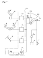
- Vehicle 1 includes a front frame 11 and a rear frame 21, and is equipped with a vertically movable mower unit 3, serving as a working device, disposed in front of front frame 11.
- Mower unit 3 is provided with a mower clutch lever 26 for clutching on/off the power transmission to rotary blades 17 in mower unit 3.
- a rear end coupling portion 18 of front frame 11 and a front end coupling portion 28 of rear frame 21 are articulately connected to each other through a vertical pivot shaft 55, so as to constitute a coupling 50.
- Front frame 11 supports a front transaxle 10 and journals left and right front axles 12L and 12R extended from front transaxle 10.
- Front wheels 13 are fixedly connected onto distal ends of front axles 12L and 12R disposed on left and right outsides of front frame 11.
- Rear frame 21 supports a rear transaxle 20 and journals left and right rear axles 22L and 22R extended from rear transaxle 20.
- Rear wheels 23 are fixedly connected onto distal ends of rear axles 22L and 22R disposed on left and right outsides of rear frame 21.
- a bonnet 8 and an engine 5 (alternatively, an electric motor) enclosed by bonnet 8 are mounted on rear frame 21, and rear transaxle 20 is disposed below engine 5.
- a front column 14, a steering wheel 4, a brake pedal 15 and a speed changing pedal 19 are mounted on a front portion of front frame 11, and a driver's seat 9 is mounted on a rear portion of front frame 11, so as to constitute a driver's section 16 above front frame 11.
- a bypass operation lever 52 projects from front column 14, and a warning device 2 is provided on front column 14.
- a front end portion of bonnet 8 is relatively rotatably fitted to driver's seat 9 so as to correspond to the articulated connection of front and rear frames 11 and 21.
- Front transaxle 10 incorporates a hydraulic motor 40a for driving front axles 12L and 12R.
- Rear transaxle 20 incorporates a hydraulic motor 40b for driving rear axles 22L and 22R.
- Two symmetric transaxles serve as front and rear transaxles 10 and 20. Otherwise, the same transaxle may serve as either front transaxle 10 or rear transaxle 20.
- a pump housing 70 incorporates a hydraulic pump 30 for supplying fluid to hydraulic motors 40a and 40b, and is supported by rear frame 21.
- a vertical engine output shaft 93 projects downward from engine 5 so as to be fixedly provided thereon with a double engine output pulley 94 consisting of an upper pulley 94a and a lower pulley 94b.
- a vertical pump shaft 31 of hydraulic pump 30 projects downward from pump housing 70 so as to be fixedly fitted thereon with an HST (hydrostatic transmission) input pulley 92.
- Vertical support shafts 24 and 95 are hung down from rear frame 21 and relatively rotatably provided thereon with respective idle rollers 25 and 96.
- a mower input shaft 112 projects upward from mower unit 3 so as to be fixedly provided thereon with a mower input pulley 111.
- a vertical support shaft 97 is hung down from front frame 11 so as to be relatively rotatably fitted thereon with an idle roller 98.
- Vertical pivot shaft 55 is extended downward so as to be relatively rotatably fitted thereon with an upper input pulley 56 and a lower output pulley 57.
- a first belt 58 is looped over upper pulley 94a, idle roller 96 and HST input pulley 92.
- a second belt 59 is looped over lower pulley 94b, idle roller 25 and upper input pulley 56.
- a third belt 60 is looped over lower output pulley 57, idle roller 98 and mower input pulley 111.
- First belt 58 transmits the power of engine 5 from engine output shaft 53 to pump shaft 31, so as to drive hydraulic pump 30.
- second and third belts 59 and 60 transmit power of engine 5 from engine output shaft 93 to mower input shaft 112, so as to drive rotary blades 17 in mower unit 3.
- a clutch operated by mower clutch lever 26 is interposed between mower input shaft 112 and rotary blades 17.
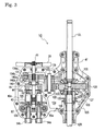
- front transaxle 10 will be described with reference to Figs. 3 to 6. Since front and rear transaxles 10 and 20 are supposed to be symmetric, description of rear transaxle 20 is omitted. Especially, in Fig. 6, the same components of rear transaxle 20 as those of front transaxle 10 are designated by the same reference numerals.
- An upper housing part 46 and a lower housing part 47 are joined to each other through a horizontal joint surface so as to constitute a transaxle housing of front transaxle 10 incorporating hydraulic motor 40a.
- An inner space of the transaxle housing is divided into a gear chamber 10a and a motor chamber 10b.
- Motor chamber 10b incorporates hydraulic motor 40a.
- Gear chamber 10a incorporates a differential gear unit 120 and a deceleration gear train 135 for transmitting power from hydraulic motor 40a to differential gear unit 120.
- a center section 62 is disposed in motor chamber 10b.
- a cylinder block 43 of hydraulic motor 40a is slidably rotatably fitted onto a vertical motor mounting surface 63 formed on center section 62.
- Pistons 42 are reciprocally fitted into cylinder block 43 and abut at heads thereof against a thrust bearing 44a of a fixed swash plate 44 clamped between upper and lower housing parts 46 and 47, and cylinder block 43 is relatively unrotatably spline-fitted on a horizontal axial motor shaft 41, thereby constituting axial piston type fixed displacement hydraulic motor 40a.
- Motor shaft 41 is relatively rotatably fitted at one end thereof into center section 62.
- Motor shaft 41 projects outward from cylinder block 43 opposite to center section 62, so as to be freely rotatably passed through a central opening 44b of fixed swash plate 44, and journalled by upper and lower housing parts 46 and 47 through a bearing 45.
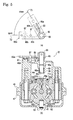
- center section 62 is bored with two kidney ports 62a and 62b serving as suction and delivery ports of hydraulic motor 40a.
- two port members 54a and 54b are clamped between upper and lower housing parts 46 and 47 and fitted into center section 62.
- Port members 54a and 54b have respective axial penetrating ports 53a and 53b, which are opened to respective kidney ports 62a and 62b.
- Hydraulic pressure fluid pipes are extended from pump housing 70 and rear transaxle 20 and connected to port members 54a and 54b so as to constitute a main HST closed circuit 36 which fluidly connects hydraulic motors 40a and 40b to hydraulic pump 30 in series.
- a hydraulic circuit 78 including main HST closed circuit 36 will be described later with reference to Fig. 6.
- center section 62 is formed therein with a bypass passage 33 bypassing between kidney ports 62a and 62b, i.e., between suction and delivery ports of hydraulic motor 40a.
- a bypass valve 71a is provided on the midway of bypass passage 33, and operatively connected to a bypass operation arm 65a so as to be selectively opened or closed by operating bypass operation arm 65a.
- center section 62 is bored therein with vertical holes 33a and 33b and a horizontal hole 33c, serving as bypass passage 33.
- Vertical holes 33a and 33b are opened to respective kidney holes 62a and 62b.
- Horizontal hole 33c is interposed between vertical holes 33a and 33b.
- An upwardly opened vertical shaft hole 64 is bored in center section 62 on the midway of horizontal hole 33c.
- a vertical bypass valve shaft 66 is relatively rotatably inserted downward into shaft hole 64.
- a ceiling wall of upper housing part 46 is formed with a boss 46a through which bypass valve shaft 66 is relatively rotatably passed.
- a flange 88 is peripherally formed on bypass valve shaft 66 below boss 46a in the transaxle housing of front transaxle 10, and a spring 89 is wound around bypass valve shaft 66 between a bottom surface of boss 46a and flange 88, so as to bias bypass valve shaft 66 downward.
- a flange 66c is peripherally formed on bypass valve shaft 66 below flange 88 and slidably rotatably pressed against a top surface of center section 62 so as to prevent bypass valve shaft 66 from falling.
- a drain hole 34a is opened into a chamber of shaft hole 64 below a bottom end of bypass valve shaft 66 fitted in shaft hole 64, and opened outward from center section 62 to a fluid sump 82 (see Fig. 6) in the transaxle housing of front transaxle 10, thereby constituting a drain passage 34 (see Fig. 6).
- a lower portion of bypass valve shaft 66 below flange 66c, serving as a rotary type bypass valve 71a, is bored with a horizontally diametrically penetrating bypass valve hole 66a, and with a vertical drain hole 66b extended downward from a middle portion of bypass valve hole 66a and downwardly opened to the chamber of shaft hole 64 below bypass valve shaft 66.
- bypass operation arm 65a is fixed on a top end of bypass valve shaft 66 projecting upward from boss 46a. As shown in Fig. 5(a), bypass operation arm 65a is switchable between a closed valve position 73 and an opened valve position 72.
- bypass valve shaft 66 rotatably integrated with bypass operation arm 65a is disposed so as to orient horizontal bypass valve hole 66a coaxially to horizontal hole 33c of bypass passage 33, i.e., to open bypass valve hole 66a to horizontal hole 33c.
- opened bypass valve 71a wholly opens bypass passage 33 so as to bypass fluid through bypass passage 33 between kidney ports 62a and 62b (i.e., the suction and delivery ports) of hydraulic motor 40a, and open the wholly opened bypass passage 33 to fluid sump 82 through drain passage 34, thereby draining the fluid from kidney ports 62a and 62b to fluid sump 82.
- bypass valve shaft 66 When bypass operation arm 65a is disposed at closed valve position 73, bypass valve shaft 66 is disposed so as to slant horizontal bypass valve hole 66a from the axial direction of horizontal hole 33c of bypass passage 33, so that the outer peripheral surface of bypass valve shaft 66 shuts off horizontal hole 33c. In this way, closed bypass valve 71a cuts off bypass passage 33 so as to prevent fluid from bypassing between kidney ports 62a and 62b of hydraulic motor 40a.
- a returning spring 85 is wound around bypass valve shaft 66 between bypass operation arm 65a and a top surface of upper housing part 46, so as to bias bypass operation arm 65a toward closed valve position 73.
- a vertical retaining pin 86 fixedly projects upward from the top surface of upper housing part 46
- a vertical pushing pin 87 fixedly projects downward from bypass operation arm 65a.
- bypass operation arm 65a When bypass operation arm 65a is moved to opened valve position 72, pushing pin 87 moves together with bypass operation arm 65a and pushes one end portion 85b of spring 85 away from the other end portion 85a retained by unmovable retaining pin 86, thereby causing the biasing force of returning spring 85.
- a detent knob 67 projects downward from bypass operation arm 65a, and an upwardly opened detent recess 46b is formed on the top surface of upper housing part 46.
- detent knob 67 is engaged into detent recess 46b so as to retain bypass operation arm 65a at opened valve position 72 against the biasing force of returning spring 85 toward closed valve position 73.
- Bypass valve 71a for hydraulic motor 40a is provided with an automatic reset mechanism 32, as shown in Fig. 5(b).
- reset mechanism 32 utilizes hydraulic pressure in drain passage 34.
- opened bypass valve 71a keeps draining fluid to fluid sump 82, thereby increasing hydraulic pressure in drain passage 34, i.e., in drain hole 34a and the chamber of shaft hole 64 below bypass valve shaft 66.
- the increased hydraulic pressure pushes bypass valve shaft 66 and bypass operation arm 65a upward against the downward biasing force of spring 89.
- bypass valve shaft 66 and bypass operation arm 65a During the rising of bypass valve shaft 66 and bypass operation arm 65a, spring 89 is compressed between stationary boss 46a and rising flange 88. Finally, detent knob 67 rising together with bypass operation arm 65a is released from detent recess 46b, and bypass operation arm 65a naturally returns to closed valve position 73 due to the biasing force of returning spring 85.
- bypass valve 71a is closed so as to shut off drain passage 34, thereby reducing hydraulic pressure in drain passage 34. Consequently, spring 88 uncompresses so as to lower bypassing valve shaft 66 to the initial height.
- Motor shaft 41 is further extended from bearing 45 to the outside of the transaxle housing through gear chamber 10a, so as to be fixedly provided thereon with a cooling fan 35.
- gear chamber 10a a motor output gear 131 is spline-fitted on motor shaft 41, and integrally formed with a brake rotor 133 on an axial end portion thereof opposite to bearing 45.
- a vertical brake shaft 140 is journalled by upper and lower housing parts 46 and 47, and projects upward from upper housing part 46 so as to be fixedly provided thereon with a brake operation arm (not shown) operatively connected to brake pedal 15 through a wire or the like.
- Brake rotor 133 is disposed between brake shoes 134a and 134b.
- brake shoe 134a is fitted to walls of housing parts 46 and 47
- brake shoe 134b is disposed between brake rotor 133 and brake shaft 140.
- a portion of brake shaft 140 facing brake shoe 134b is partly cut away so as to be sectionally semicircular, i.e., have a flat cam surface 140a facing brake shoe 134b.
- brake shaft 140 When brake pedal 15 is depressed, brake shaft 140 is rotated so as to orient cam surface 140a slantwise from brake shoe 134b. Slanted cam surface 140a presses one end edge 140b thereof against brake shoe 134b toward brake shoe 134a, so as to pinch brake rotor 133 between brake shoes 134a and 134b, thereby braking motor shaft 41.
- a counter shaft 139 parallel to motor shaft 41, is disposed in gear chamber 10a.
- a diametrically small and axially long gear 137 is relatively rotatably fitted on counter shaft 139, and a diametrically large gear 136 is relatively unrotatably fitted on one axial end portion of gear 137.
- Diametrically large gear 136 meshes with motor output gear 131, and diametrically small gear 137 meshes with a bull gear 121 of differential gear unit 120, thereby constituting deceleration gear train 135 interposed between motor shaft 41 and differential gear unit 120.
- Differential gear unit 120 includes bull gear 121, a pinion shaft 122, a differential pinion 123 and differential side gears 124.
- Bull gear 121 meshes with diametrically small gear 137 of deceleration gear train 135, as mentioned above.
- Pinion shaft 122 projects centripetally from an inner peripheral portion of bull gear 121.
- Differential pinion 123 is relatively rotatably supported on pinion shaft 122 and meshes with differential side gears 124 fixed on proximal ends of respective front axles 12L and 12R, so as to differentially transmit rotation of bull gear 121 to axles 12L and 12R.
- Differential gear unit 120 is provided with a differential locking mechanism 125.
- Differential locking mechanism 125 includes a slider 128 axially slidably fitted on one of axles 12L and 12R, and a lock pin 127 fixed to slider 128 and extended in parallel to axles 12L and 12R.
- Lock pin 127 is axially slidably fitted in differential side gear 124 fixed on the one of axles 12L and 12R.
- a shifter fork 126 is engaged onto slider 128 so as to be switchable between a differential position and a differential locking position. When shifter fork 126 is disposed at the differential position, lock pin 127 is disposed outside bull gear 121 so as to allow differential rotation of axles 12L and 12R.
- shifter fork 126 is disposed at the differential locking position, lock pin 127 is engaged into bull gear 121 so as to rotatably integrate axles 12L and 12R with each other.
- Hydraulic circuit 78 includes main HST closed circuit 36, which fluidly connects hydraulic motors 40a and 40b to hydraulic pump 30 in series so as to drive front axles 12L and 12R and rear axles 22L and 22R.
- a charge pump 81 is disposed on pump shaft 31 so as to be driven by power of engine 5.
- Charge pump 81 sucks fluid from a fluid tank 100 and supplies the fluid to main HST closed circuit 36 through either charge (check) valve 81a or 81b.
- Main HST closed circuit 36 includes a passage 36a interposed between hydraulic pump 30 and hydraulic motor 40a, a passage 36b interposed between hydraulic pump 30 and hydraulic motor 40b, and a passage 36c interposed between hydraulic motors 40a and 40b.
- hydraulic fluid pipes are connected among pump housing 70 and the transaxle housings of front and rear transaxles 10 and 20, so as to constitute passages 36a, 36b and 36c.
- the pipes connected to port members 54a and 54b of front transaxle 10 serve as passages 36a and 36c.
- Rear transaxle 20 has similar port members, to which the pipes are connected so as to serve as passages 36b and 36c.
- bypass passage 33 including bypass valve 71a is interposed between passages 36a and 36c so as to bypass between suction and delivery ports (referring to Fig. 5(b), kidney ports 62a and 62b) of hydraulic motor 40a.
- a bypass passage 74 including a bypass valve 71b is interposed between passages 36b and 36c so as to bypass between suction and delivery ports of hydraulic motor 40b.
- a bypass passage 75 including a bypass valve 7 1 c is interposed between passages 36a and 36b so as to bypass between suction and delivery ports of hydraulic pump 30.
- Drain passage 34 is extended from bypass valve 71a and opened to a fluid sump 82 in the transaxle housing of front transaxle 10.
- a drain passage 76 is extended from bypass valve 71b and opened to a fluid sump 83 in the transaxle housing of rear transaxle 20.
- a drain passage 77 is extended from bypass valve 71c and opened to a fluid sump 84 in pump housing 70.
- Pipes are extended from pump housing 70 and the transaxle housings of front and rear transaxles 10 and 20, and collected as a passage 120 connected to fluid tank 100, thereby fluidly connecting fluid sumps 82, 83 and 84 to fluid tank 100.
- bypass valve 71 a in front transaxle 10 is constructed as mentioned above.
- Bypass valve 71b in rear transaxle 20 and bypass valve 71c in pump housing 70 are constructed similar to bypass valve 71a.
- the above described bypass valve 71a is a rotary valve.
- each of bypass valves 71a, 71b and 71c may be any type valve if it can bypass between suction and delivery ports of each of hydraulic motor 40a, 40b and hydraulic pump 30.
- an alternative bypass valve includes a slidable spool.
- An alternative bypass valve pushes a cylinder block away from a center section so as to be opened to a fluid sump.
- An alternative bypass valve uses a pair of check valves: one interposed between a suction port and a fluid sump; and the other interposed between a delivery port and the fluid sump. During bypassing, the bypass valve mechanically opens both the check valves simultaneously and evenly, so as to forcibly drain fluid from the suction and delivery ports to the fluid sump.
- bypass valves 71b and 71c are provided with respective bypass operation arms 65b and 65c.
- bypass operation lever 52 (see Fig. 1) interlocks with bypass operation arms 65a, 65b and 65c, so as to enable simultaneous operation of bypass valves 71a, 71b and 71c. Namely, bypass operation lever 52 is switchable between a closed valve position for simultaneously closing bypass valves 71a, 71b and 71c and an opened valve position for simultaneously opening bypass valves 71a, 71b and 71c.
- bypass valve 71a of hydraulic motor 40a is provided with the above-mentioned automatic reset mechanism 32 using hydraulic pressure in drain passage 34.
- bypass valves 71b and 71c are provided with respective automatic reset mechanisms using hydraulic pressure in respective drain passages 76 and 77.
- bypass operation lever 52 is forgotten to be returned to the closed valve position before traveling of vehicle 1, unclosed bypass valves 71 a, 71b and 71c drain fluid to respective fluid sumps 82, 83 and 84, and increase hydraulic pressure in each of drain passages 34, 76 and 77 which releases each of bypass operation arms 65a, 65b and 65c from the corresponding opened valve position, and returns it to the corresponding closed valve position.
- vehicle 1 is provided with a reset system 113 for automatically closing unclosed bypass valve 71a or 71b in association with another (manual) operation, as shown in Fig. 7.
- Fig. 7 illustrates reset system 113 including reset mechanisms 114,115,116 and 117.
- reset mechanisms 114 to 117 can be enough for realizing reset system 113.
- Each of reset mechanisms 114, 116 and 117 associates the resetting of bypass valves 71 a and 71b with an operation required before starting of engine 5, i.e., depression of brake pedal 15, a clutching-off operation of mower unit 3 or an operator sitting on seat 9. Due to any one of reset mechanisms 114, 116 and 117, bypass valves 71a and 71b are surely closed before starting of engine 5. Reset mechanism 115 associates the resetting of bypass valves 71a and 71b with depression of speed changing pedal 19 for acceleration after starting of engine 5.
- each of reset mechanisms 114, 116 and 117 can also automatically close unclosed bypass valve 71a or 71b in association with depression of brake pedal 15, a clutch-off operation of mower unit 3 or an operator sitting on seat 9 even if bypass valve 71a or 71b remains open after starting of engine 5.
- Reset mechanism 114 shown in Figs. 7, 8 and 9 will be described.
- Reset mechanism 114 operatively connects brake pedal 15 to bypass operation arms 65a and 65b.
- Brake pedal 15 is operatively connected to the brakes (see Fig. 3) for braking respective hydraulic motors 40a and 40b.
- Brake pedal 15 is necessarily depressed before starting of engine 5.
- Brake pedal 15 is pivoted at a vertical intermediate portion thereof on a horizontal pivot 48, and provided on a top thereof with a pedal plate 15a and formed with an arm 15d opposite to pedal plate 15a with respect to pivot 48 (extended downward from pivot 48), so that, when pedal plate 15a of brake pedal 15 is depressed, the arm 15d is rotated rearward.
- the arm 15d of brake pedal 15 is formed with arcuate slots 15b and 15c disposed concentrically around pivot 48.
- a connection rod 103 is slidably fitted at a front end thereof into upper slot 15b, and pivotally connected at a rear end thereof to bypass operation arm 65a adjacent to bypass valve shaft 66.
- a restriction rod 104 is pivotally connected at a front end thereof to a tip of bypass operation arm 65a opposite to bypass valve shaft 66.
- a stopper 107 includes a guide hole 107a through which restriction rod 104 is axially slidably passed, and provided on a rear end thereof with an engaging portion 104a, opposite to the tip of bypass operation arm 65a with respect to stopper 107.
- bypass operation arm 65a is disposed at closed valve position 73 and the front end of connection rod 103 is disposed at a rear end of slot 15b, so that connection rod 103 is kept stationary during the rearward movement of slot 15b by depression of pedal plate 15a of brake pedal 15, thereby keeping bypass operation arm 65a at closed valve position 73.
- bypass operation arm 65a is disposed at opened valve position 72 (not shown)
- the front end of connection rod 103 is disposed at a front end of slot 15b, so that connection rod 103 is moved together with rearward movement of slot 15b by depression of pedal plate 15a of brake pedal 15 so as to forcibly rotating bypass operation arm 65a to closed valve position 73.
- a shock absorber 99 is interposed in connection rod 103 so as to moderate axial movement of connection rod 103 caused by depression of pedal plate 15a of brake pedal 15.
- Shock absorber 99 includes a casing 99a which incorporates a compressed spring 99b interposed between divided front and rear portions of connection rod 103.
- a shock absorber 99 may be interposed in restriction rod 104 if it achieves the same purpose.
- connection rod 105 is slidably fitted at a front end thereof into lower slot 15c, and pivotally connected at a rear end thereof to bypass operation arm 65b adjacent to a bypass valve shaft 68 serving as bypass valve 71b (similar to bypass valve shaft 66 serving as bypass valve 71a).
- a restriction rod 106 is pivotally connected at a front end thereof to a tip of bypass operation arm 65b opposite to bypass valve shaft 68.
- a shock absorber may be interposed in connection rod 105 or restriction rod 106.
- a stopper 108 includes a guide hole 108a through which restriction rod 106 is axially slidably passed, and provided on a rear end thereof with an engaging portion 106a, opposite to the tip of bypass operation arm 65b with respect to stopper 108.
- bypass operation arm 65b When bypass operation arm 65b is disposed at closed valve position 73, engaging portion 106a is disposed apart from stopper 108, so as not to prevent rotation of bypass operation arm 65b.
- engaging portion 106a When bypass operation arm 65b is moved to opened valve position 72, engaging portion 106a finally abuts against stopper 108 so as to define opened valve position 72 of bypass operation arm 65b.
- bypass operation arm 65b is disposed at closed valve position 73 and the front end of connection rod 105 is disposed at a rear end of slot 15c, so that connection rod 105 is kept stationary during the rearward movement of slot 15c by depression of pedal plate 15a of brake pedal 15, thereby keeping bypass operation arm 65b at closed valve position 73.
- bypass operation arm 65b is disposed at opened valve position 72.
- the front end of connection rod 105 is disposed at a front end of slot 15c.
- pedal plate 15a of brake pedal 15 is depressed, connection rod 105 moves rearward together with the rearwardly moving slot 15c, thereby forcibly rotating bypass operation arm 65b from opened valve position 72 to closed valve position 73.
- reset mechanism 114 forcibly closes any unclosed one of bypass valves 71 a and 71b in association with the depression of brake pedal 15 required before starting of engine 5, so as to ensure proper traveling of vehicle 1.
- a brake pedal may be disposed between front and rear transaxles 10 and 20 in the fore-and-aft direction of a vehicle.
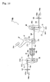
- a reset mechanism 114a shown in Fig. 10 is a rearrangement reset mechanism 114, such as to be adapted for a brake pedal 27 disposed between front and rear transaxles 10 and 20.
- Brake pedal 27 is pivoted at a vertical intermediate portion thereof on a horizontal pivot 37, and provided on a top thereof with a pedal plate 27a and formed with an arm 27d opposite to pedal plate 27a with respect to pivot 37 (extended downward from pivot 37), so that, when pedal plate 27a of brake pedal 27 is depressed, the arm 27d is rotated rearward.
- the arm 27d of brake pedal 27 is formed with arcuate slots 27b and 27c disposed concentrically around pivot 37.
- a connection rod 143 is slidably fitted at a rear end thereof into upper slot 27b, and pivotally connected at a front end thereof to bypass operation arm 65a adjacent to bypass valve shaft 66 serving as bypass valve 71a.
- a restriction rod 144 is pivotally connected at a rear end thereof to a tip of bypass operation arm 65a opposite to bypass valve shaft 66. Restriction rod 144 is axially slidably passed through guide hole 107a of stopper 107, and provided on a front end thereof with an engaging portion 144a, so as to define opened valve position 72 of bypass operation arm 65a, similar to fore-and-aft reversed restriction rod 104 with engaging portion 104a.
- connection rod 143 When bypass operation arm 65a is disposed at closed valve position 73 (as drawn in solid lines in Fig. 10), the rear end of connection rod 143 is disposed at a rear end of slot 27b, so that connection rod 143 is kept stationary during the rearward movement of slot 27b by depression of pedal plate 27a of brake pedal 27, thereby keeping bypass operation arm 65a at closed valve position 73.
- bypass operation arm 65a When bypass operation arm 65a is disposed at opened valve position 72 (as drawn in phantom lines in Fig.
- connection rod 143 is disposed at a front end of slot 27b, so that, when pedal plate 27a of brake pedal 27 is depressed, connection rod 143 is moved together with the rearward movement of slot 27b so as to forcibly rotate bypass operation arm 65a from opened valve position 72 to closed valve position 73.
- a connection rod 145 is slidably fitted at a front end thereof into lower slot 27c, and pivotally connected at a rear end thereof to bypass operation arm 65b adjacent to bypass valve shaft 68 serving as bypass valve 71b.
- a restriction rod 146 is pivotally connected at a front end thereof to a tip of bypass operation arm 65b opposite to bypass valve shaft 68. Restriction rod 146 is axially slidably passed through guide hole 108a of stopper 108, and provided on a rear end thereof with an engaging portion 146a, so as to define opened valve position 72 of bypass operation arm 65b, similar to restriction rod 106 with engaging portion 106a.
- connection rod 145 When bypass operation arm 65b is disposed at closed valve position 73 (as drawn in solid lines in Fig. 10), the front end of connection rod 145 is disposed at a rear end of slot 27c, so that connection rod 145 is kept stationary during the rearward movement of slot 27c by depression of pedal plate 27a of brake pedal 27, thereby keeping bypass operation arm 65b at closed valve position 73.
- bypass operation arm 65b When bypass operation arm 65b is disposed at opened valve position 73 (as drawn in phantom lines in Fig.
- connection rod 145 is disposed at a front end of slot 27c, so that, when pedal plate 27a of brake pedal 27 is depressed, connection rod 145 is moved together with the rearward movement of slot 27c so as to forcibly rotate bypass operation arm 65b from opened valve position 72 to closed valve position 73.
- shock absorber 99 is interposed in connection rod 143.
- shock absorber 99 may be interposed in any of rods 144, 145 and 146.
- Speed changing pedal 19 is seesaw-like pivoted at its fore-and-aft intermediate boss portion 19c on a horizontal pivot 38.
- a front pedal plate 19a for changing forward traveling speed of the vehicle is provided on speed changing pedal 19 in front of pivot 38, and a rear pedal plate 19b for changing backward traveling speed of the vehicle is provided on speed changing pedal 19 behind pivot 38.
- Speed changing pedal 19 is operatively connected to a movable swash plate 30a of hydraulic pump 30 (see Fig.
- movable swash plate 30a is rotated in one direction from a neutral position by depression of front pedal plate 19a so as to supply hydraulic motors 40a and 40b with fluid for forward traveling, and it is rotated in the other direction from the neutral position by depression of rear pedal plate 19b so as to supply hydraulic motors 40a and 40b with fluid for rearward traveling.
- An upright reset arm 29 is disposed on a lateral side of speed changing pedal 19.
- Reset arm 29 is pivoted at a vertically intermediate portion thereof on a horizontal pivot 48 extended from front frame 11.
- Reset arm 29 is formed at a lower portion thereof below pivot 48 with arcuate slots 29b and 29c disposed concentrically around pivot 48.
- Reset arm 29 is formed at an upper portion thereof above pivot 48 with a rearwardly opened V-like shaped recess 29a which is deepest at a vertical intermediate portion thereof.
- An arm 39 is extended forward from boss portion 19c and rotatably integral with speed changing pedal 19.
- a roller 39a is pivoted on a front end of arm 39.
- Roller 39a is rotatably fitted forward into recess 29a.
- a spring 49 is wound around pivot 48 and interposed between reset arm 29 and front frame 11 so as to bias reset arm 29 for engaging roller 39a into the deepest portion of recess 29a.
- connection rod 154 is interposed between slot 29b and bypass operation arm 65a, and a restriction rod 155 with an engaging portion 155a is connected through stopper 107 to bypass operation arm 65a, similar to connection rod 103 and restriction rod 104.
- a connection rod 156 is interposed between slot 29c and bypass operation arm 65b, and a restriction rod 157 with an engaging portion 157a is connected through stopper 108 to bypass operation arm 65b, similar to connection rod 105 and restriction rod 106.
- connection rod 154 or 156 connected to bypass operation arm 65a or 65b disposed at opened valve position 72 is pushed together with rearward movement of corresponding slot 29b or 29c so as to forcibly rotate corresponding bypass operation arm 65a or 65b from opened valve position 72 to closed valve position 73.
- reset mechanism 115 forcibly closes any unclosed one of bypass valves 71 a and 71b in association with the depression of speed changing pedal 19 required for acceleration after starting of engine 5, so as to ensure proper traveling of vehicle 1.
- shock absorber 99 is interposed in connection rod 154.
- shock absorber 99 may be interposed in any of rods 155, 156 and 157.
- Reset mechanism 116 will be described with reference to Figs. 1 and 7.
- Mower clutch lever 26 provided on mower unit 3 is connected to bypass operation arms 65a and 65b through a linkage mechanism similar to those shown in Figs. 8 to 10, so that any of bypass operation arms 65a and 65b disposed at opened valve position 72 is forcibly returned to closed valve position 73 by operation of mower clutch lever 26 for clutching off mower unit 3.
- Mower clutch lever 26 is necessarily operated for clutching off mower unit 3 before starting of engine 5. Therefore, all of bypass valves 71a and 71b are surely closed before starting of engine 5.
- Reset mechanism 117 will be described with reference to Figs. 1 and 7.
- a pressure sensing switch among others serves as a seat switch 7 to be switched on when an operator sits on seat 9.
- seat switch 7 When seat switch 7 is switched on (detects sitting of an operator on seat 9), an electric motor 51 is activated for forcibly rotating bypass operation arms 65a and 65b from respective opened valve positions 72 to respective closed valve positions 73.
- An operator necessarily sits on seat 9 before starting of engine 5. Therefore, all of bypass valves 71a and 71b are surely closed before starting of engine 5.
- Each of reset mechanisms 114 to 117 illustrated in Figs. 7 to 11 is connected to bypass operation arms 65a and 65b for operating bypass valves 71a and 71b of hydraulic motors 40a, 40b. Additionally, each of reset mechanisms 114 to 117 can also be connected to bypass operation arm 65c (see Fig. 6), so as to reset any of bypass valves 71a, 71b and 71c of hydraulic motors 40a, 40b and hydraulic pump 30.
- any of reset mechanisms 32, 114 (114a), 115, 116 and 117 is adaptable to each of vehicle driving hydraulic circuits 79 and 80 shown in Figs. 12 and 13.
- the same components of hydraulic circuits 79 and 80 as those in hydraulic circuit 78 are designated by the same reference numerals. Only distinctive points of hydraulic circuits 79 and 80 from hydraulic circuit 78 will be described.
- a front transaxle 147 incorporates hydraulic motor 40a for driving front axles 12L and 12R, and a rear transaxle 148 integrally incorporates hydraulic pump 30 and hydraulic motor 40b for driving rear axles 22L and 22R.
- Pipes are interposed between front transaxle 147 and rear transaxle 148 so as to fluidly connect hydraulic motors 40a and 40b to hydraulic pump 30 in series.
- hydraulic motor 40a is provided with a bypass passage 150, a bypass valve 152a and a bypass operation arm 153a, similar to bypass passage 33, bypass valve 71a and bypass operation arm 65a.
- hydraulic motor 40b is provided with a bypass passage 151, a bypass valve 152b and a bypass operation arm 153b, similar to bypass passage 74, bypass valve 71b and bypass operation arm 65b.
- Hydraulic pump 30 is provided with no component for bypassing fluid between suction and delivery ports of hydraulic pump 30. Therefore, bypassing components in hydraulic circuit 79 are fewer than those of hydraulic circuit 78.
- Each of bypass valves 152a and 152b may be provided with a reset mechanism similar to reset mechanism 32, so as to be forcibly closed according to increase of hydraulic pressure in the drain passage therefrom.
- any of reset mechanisms 114, 115, 116 and 117 may operatively connect to bypass operation arms 153a and 153b so as to automatically close any unclosed one of bypass valves 152a and 152b.
- a front transaxle 160 incorporates a pair of hydraulic motors 162 and 163 for driving respective left and right front axles 12L and 12R.
- Hydraulic motors 162 and 263 are fluidly connected to each other in parallel, so as to differentially drive front axles 12L and 12R without a mechanical differential unit.
- Front wheels 13 are steerably connected to respective front axles 12L and 12R.
- One of hydraulic motors 162 and 163 (in this embodiment, hydraulic motor 162) is changed in displacement according to turning of front wheels 13, so as to prevent drag of front wheels 13 or rear wheels 23 during turning of the vehicle.
- a pair of pipes 164 and 165 are extended from rear transaxle 148, a pair of pipes 166 and 167 are extended from front transaxle 160, and a drive mode changing valve 161 is interposed between the pair of pipes 164 and 165 and the pipes 166 and 167.
- the drive mode changing valve 161 is switchable between a four-wheel drive mode position (4WD) and a two-wheel drive mode position (2WD).
- 4WD four-wheel drive mode position
- 2WD two-wheel drive mode position
- pipe 164 is connected to pipe 166
- pipe 165 is connected to pipe 167, thereby fluidly connect hydraulic motors 162 and 163 to hydraulic pump 30 and motor 40b.
- hydraulic motor 40b is provided with bypass passage 151, bypass valve 152b and bypass operation arm 153b.
- Front transaxle 160 incorporates no bypass mechanism for hydraulic motors 162 and 163.
- drive mode changing valve 161 is disposed at the two-wheel drive mode position (2WD) so as to allow the rotatability of front axles 12L and 12R, thereby enabling the vehicle to be hauled.
- Bypass valve 152b in rear transaxle 148 may be provided with a reset mechanism similar to reset mechanism 32, so as to be forcibly closed according to an increase of hydraulic pressure in the drain passage therefrom.
- any of reset mechanisms 114, 115, 116 and 117 may operatively connect to bypass operation arm 153b so as to automatically close unclosed bypass valve 152b.
Landscapes
- Engineering & Computer Science (AREA)
- General Engineering & Computer Science (AREA)
- Mechanical Engineering (AREA)
- Chemical & Material Sciences (AREA)
- Combustion & Propulsion (AREA)
- Transportation (AREA)
- Control Of Fluid Gearings (AREA)
- Motor Power Transmission Devices (AREA)
Abstract
Description
- The invention relates to a hydraulic transaxle including a hydraulic motor for driving an axle, provided with a bypass valve bypassing between suction and delivery ports of the hydraulic motor, and relates to a hydraulically driven vehicle equipped with one or more hydraulic motors for driving an axle or respective axles, and provided with one or more bypass valves each of which bypasses between suction and delivery ports of each of the hydraulic motors.
- As disclosed in
US Patent Nos. 6,732,828 and6,845,837 , there is a conventional, well-known hydraulically driven vehicle equipped with respective hydraulic motors for front and rear axles. The hydraulic motors are provided with respective bypass valves each of which is to be opened for bypassing fluid between the suction and delivery ports of each of the hydraulic motors. When the vehicle is hauled, an operator performs the operation for opening the bypass valves so as to bypass fluid between the suction and delivery ports of each of the hydraulic motors and drain the fluid to a fluid sump, thereby allowing the hydraulic motors to act as pumps driven by the rotating axles regardless of a hydraulic pump fluidly connected to the hydraulic motors. The operation for opening the bypass valves is also performed for fluid connection of hydrostatic transaxles including the respective hydraulic motors or for releasing air during exchanging of fluid. - However, it may happen that an operator forgets to close one or more of the bypass valves after the need for opening the bypass valves has passed. Unclosed bypass valves cause inactivation of the corresponding hydraulic motor, thereby resulting in unstable travel of the vehicle because of a difference in rotary speed between the front and rear axles. Further, in the case that the hydraulic motors are fluidly connected to the hydraulic pump in series and the bypass valve of the upstream hydraulic motor is not closed, the downstream hydraulic motor is also inactivated, i.e., both of the hydraulic motors are inactivated, whereby the vehicle cannot travel.
- Further, during traveling of the vehicle, an unclosed bypass valve causes insufficient dynamic braking action of the hydraulic pressure of the fluid delivered from the hydraulic pump, thereby preventing the vehicle from being properly decelerated or braked.
- Further, the fluid drained from an unclosed bypass valve increases pressure of the fluid sump in a transaxle housing incorporating the corresponding hydraulic motor, thereby causing leakage of the fluid from the transaxle housing. Consequently, in the past the transaxle housing has been expensively sealed against such an unexpected leak of fluid.
- A first object of the invention is to provide a hydraulic transaxle safe from the problems caused by not closing a bypass valve of a hydraulic motor for driving an axle.
- To achieve the first object of the invention, a transaxle according to a first aspect of the present invention comprises: an axle; a hydraulic pump driven by a prime mover; a hydraulic motor fluidly connected to the hydraulic pump so as to drive the axle; a bypass valve to be opened for bypassing fluid between suction and delivery ports of the hydraulic motor; a bypass operation device for selectively opening or closing the bypass valve; and a reset mechanism operatively connected to the bypass operation device so as to automatically close the bypass valve when the bypass valve is not closed.
- Therefore, even if the bypass operation device has been operated for opening the bypass valve, but has been forgotten to be operated for closing the bypass valve before traveling of a vehicle equipped with the transaxle, i.e., even if the bypass valve is not closed before traveling of the vehicle, the reset mechanism forcibly closes the unclosed bypass valve so as to ensure proper travel of the vehicle. That is, the transaxle performs proper output rotation and proper dynamic braking action of the hydraulic motor during traveling of the vehicle. Further, with respect to a transaxle housing incorporating the hydraulic motor, the closing of the bypass valve by the reset mechanism prevents a volumetric increase of fluid drained from the bypass valve, thereby preventing fluid from leaking from the transaxle housing, and thereby reducing costs for ensuring the anti-pressure property of the transaxle housing.
- Preferably, the reset mechanism is activated to close the unclosed bypass valve according to an operation required for starting the prime mover. Therefore, the bypass is surely closed before starting the prime mover. The operation required for starting the prime mover is, for instance, a braking operation (depression of a brake pedal), an operator sitting on a seat, or a clutch-off operation of a working device.
- Preferably, the reset mechanism is activated to close the unclosed bypass valve according to an operation required for the traveling of a vehicle after starting the prime mover. Therefore, the bypass valve is surely closed during travel of the vehicle even after starting the prime mover. The operation required for traveling of the vehicle after starting the prime mover is, for instance, an operation for acceleration of the vehicle (depression of a speed changing pedal), i.e., an operation for increasing the displacement of the hydraulic pump.
- Preferably, the hydraulic transaxle further comprises a drain passage connected to the bypass valve, and the reset mechanism is activated according to an increase of hydraulic pressure in the drain passage. This reset mechanism uses an increase of hydraulic pressure in the drain passage necessarily caused by opening the bypass valve. Therefore, the reset mechanism requires no complicated linkage for associating another operation device with the bypass operation device. Further, the reset mechanism can be assembled together with the hydraulic motor.
- Preferably, the hydraulic transaxle further comprises a warning device for warning when it is detected that the bypass valve is opened. Therefore, even if the bypass valve remains unclosed regardless of the reset mechanism (for instance, because of trouble of the reset mechanism), an operator is alarmed at the warning by the warning device and operates the bypass operation device so as to reset (close) the unclosed bypass valve.
- A second object of the invention is to provide a hydraulically driven vehicle safe from the problems caused by not closing any of bypass valves of respective hydraulic motors for driving respective axles.
- To achieve the second object of the invention, a hydraulically driven vehicle according to a second aspect of the invention comprises: a plurality of axles; a prime mover; a hydraulic pump driven by the prime mover; a plurality of hydraulic motors fluidly connected to the hydraulic pump so as to drive the respective axles; a plurality of bypass valves each of which is to be opened for bypassing fluid between suction and delivery ports of each of the hydraulic motors; a plurality of bypass operation devices for selectively opening or closing the respective bypass valves; and a reset mechanism operatively connected to the bypass operation devices so as to automatically close any unclosed one of the bypass valves.
- Therefore, even if any of the bypass operation devices has been operated for opening the bypass valve, but has been forgotten to be operated for closing the bypass valve before traveling of the vehicle, i.e., even if any of the bypass valves is not closed before the traveling of the vehicle, the reset mechanism forcibly closes the unclosed bypass valve, i.e., closes all the bypass valves so as to ensure proper travel of the vehicle. That is, the vehicle can travel with proper output rotation and proper dynamic braking action of the hydraulic motors. Further, with respect to a transaxle housing (or transaxle housings) incorporating the hydraulic motors, the closing of the bypass valves by the reset mechanism prevents a volumetric increase of fluid drained from the bypass valves, thereby preventing fluid from leaking from the transaxle housing(s), and thereby reducing costs for ensuring the anti-pressure property of the transaxle housing(s).
- Preferably, the reset mechanism is activated so as to close any unclosed one of the bypass valves according to an operation required for starting the prime mover. Therefore, all of the bypass valves are surely closed before starting of the prime mover. The operation required for starting the prime mover is, for instance, a braking operation (depression of a brake pedal), an operator sitting on a seat, or a clutch-off operation of a working device.
- Preferably, the reset mechanism is activated so as to close any unclosed one of the bypass valves according to an operation required for the traveling of the vehicle after starting the prime mover. Therefore, all of the bypass valves are surely closed during travel of the vehicle even after starting the prime mover. The operation required for the traveling of the vehicle after starting the prime mover is, for instance, an operation for acceleration of the vehicle (depression of a speed changing pedal), i.e., an operation for increasing the displacement of the hydraulic pump.
- Preferably, the hydraulically driven vehicle further comprises drain passages connected to the respective bypass valves, and the reset mechanism is activated so as to close any unclosed one of the bypass valves according to an increase of hydraulic pressure in any of the drain passages. This reset mechanism uses an increase of hydraulic pressure in the drain passage necessarily caused by opening the bypass valve. Therefore, the reset mechanism requires no complicated linkage for associating another operation device with the bypass operation devices. Further, the reset mechanism can be divided and assembled together with the respective hydraulic motors.
- Preferably, the hydraulically driven vehicle further comprises a warning device for warning when it is detected that any of the bypass valves is opened. Even if any of the bypass valves remains unclosed regardless of the reset mechanism, an operator is alarmed at the warning by the warning device.
- These, further and other objects, features and advantages will appear more fully from the following description with reference to the accompanying drawings.
-
- Fig. 1 is a side view partly in section of a riding lawn mower as an embodiment of the hydraulically driven vehicle according to the present invention.
- Fig. 2 is a plan view partly in section of the vehicle showing a power train.
- Fig. 3 is a plan view of a front transaxle used for the vehicle, from which an upper housing part is removed.
- Fig. 4 is a sectional rear view of the transaxle showing a hydraulic motor therein.
- Fig. 5 illustrates an automatic reset mechanism for a bypass valve of the hydraulic motor, wherein Fig. 5(a) is a plan view of a bypass operation arm, and Fig. 5(b) is a sectional side view of the hydraulic motor with the bypass valve and the reset mechanism.
- Fig. 6 is a hydraulic circuit diagram for driving the vehicle.
- Fig. 7 is a systematic diagram of the reset mechanism.
- Fig. 8 is a structural view of a reset mechanism associated with a braking operation when both bypass valves of the respective front and rear transaxles are closed.
- Fig. 9 is a structural view of the reset mechanism associated with a braking operation when one of the bypass valves is opened.
- Fig. 10 is a structural view of a reset mechanism associated with an operation of a brake pedal disposed between the front and rear transaxles, when both the bypass valves of the respective front and rear transaxles are closed.
- Fig. 11 is a structural view of a reset mechanism associated with a speed changing operation.
- Fig. 12 is a structural diagram of a hydraulic circuit between the front and rear transaxles of the vehicle, wherein the rear transaxle incorporates a hydraulic pump and a hydraulic motor.
- Fig. 13 is a structural diagram of a hydraulic circuit between the front and rear transaxles of the vehicle, wherein the rear transaxle incorporates a hydraulic pump and a hydraulic motor, and the front transaxle incorporates a pair of hydraulic motors fluidly connected to the hydraulic pump in parallel.
- Description will be given of a general structure of a
vehicle 1 shown in Figs. 1 and 2, which is a riding lawn mower serving as an embodiment of a hydraulically driven vehicle according to the invention.Vehicle 1 includes afront frame 11 and arear frame 21, and is equipped with a verticallymovable mower unit 3, serving as a working device, disposed in front offront frame 11.Mower unit 3 is provided with a mowerclutch lever 26 for clutching on/off the power transmission torotary blades 17 inmower unit 3. - A rear
end coupling portion 18 offront frame 11 and a frontend coupling portion 28 ofrear frame 21 are articulately connected to each other through avertical pivot shaft 55, so as to constitute acoupling 50.Front frame 11 supports afront transaxle 10 and journals left and rightfront axles front transaxle 10.Front wheels 13 are fixedly connected onto distal ends offront axles front frame 11.Rear frame 21 supports arear transaxle 20 and journals left and rightrear axles rear transaxle 20.Rear wheels 23 are fixedly connected onto distal ends ofrear axles rear frame 21. - A bonnet 8 and an engine 5 (alternatively, an electric motor) enclosed by bonnet 8 are mounted on
rear frame 21, andrear transaxle 20 is disposed belowengine 5. Afront column 14, a steering wheel 4, abrake pedal 15 and aspeed changing pedal 19 are mounted on a front portion offront frame 11, and a driver'sseat 9 is mounted on a rear portion offront frame 11, so as to constitute a driver'ssection 16 abovefront frame 11. Abypass operation lever 52 projects fromfront column 14, and awarning device 2 is provided onfront column 14. A front end portion of bonnet 8 is relatively rotatably fitted to driver'sseat 9 so as to correspond to the articulated connection of front andrear frames - A power train of
vehicle 1 will be described with reference to Figs. 1 and 2.Front transaxle 10 incorporates ahydraulic motor 40a for drivingfront axles Rear transaxle 20 incorporates ahydraulic motor 40b for drivingrear axles rear transaxles front transaxle 10 orrear transaxle 20. Apump housing 70 incorporates ahydraulic pump 30 for supplying fluid tohydraulic motors rear frame 21. - A vertical
engine output shaft 93 projects downward fromengine 5 so as to be fixedly provided thereon with a doubleengine output pulley 94 consisting of anupper pulley 94a and alower pulley 94b. Avertical pump shaft 31 ofhydraulic pump 30 projects downward frompump housing 70 so as to be fixedly fitted thereon with an HST (hydrostatic transmission)input pulley 92.Vertical support shafts rear frame 21 and relatively rotatably provided thereon with respectiveidle rollers mower input shaft 112 projects upward frommower unit 3 so as to be fixedly provided thereon with amower input pulley 111. A vertical support shaft 97 is hung down fromfront frame 11 so as to be relatively rotatably fitted thereon with anidle roller 98.Vertical pivot shaft 55 is extended downward so as to be relatively rotatably fitted thereon with anupper input pulley 56 and alower output pulley 57. - A
first belt 58 is looped overupper pulley 94a,idle roller 96 andHST input pulley 92. Asecond belt 59 is looped overlower pulley 94b,idle roller 25 andupper input pulley 56. Athird belt 60 is looped overlower output pulley 57,idle roller 98 and mower inputpulley 111.First belt 58 transmits the power ofengine 5 from engine output shaft 53 to pumpshaft 31, so as to drivehydraulic pump 30. Simultaneously, second andthird belts engine 5 fromengine output shaft 93 tomower input shaft 112, so as to driverotary blades 17 inmower unit 3. Inmower unit 3, a clutch operated by mowerclutch lever 26 is interposed betweenmower input shaft 112 androtary blades 17. - Representative
front transaxle 10 will be described with reference to Figs. 3 to 6. Since front andrear transaxles rear transaxle 20 is omitted. Especially, in Fig. 6, the same components ofrear transaxle 20 as those offront transaxle 10 are designated by the same reference numerals. - An
upper housing part 46 and alower housing part 47 are joined to each other through a horizontal joint surface so as to constitute a transaxle housing offront transaxle 10 incorporatinghydraulic motor 40a. An inner space of the transaxle housing is divided into agear chamber 10a and amotor chamber 10b.Motor chamber 10b incorporateshydraulic motor 40a.Gear chamber 10a incorporates adifferential gear unit 120 and adeceleration gear train 135 for transmitting power fromhydraulic motor 40a todifferential gear unit 120. Acenter section 62 is disposed inmotor chamber 10b. Acylinder block 43 ofhydraulic motor 40a is slidably rotatably fitted onto a verticalmotor mounting surface 63 formed oncenter section 62.Pistons 42 are reciprocally fitted intocylinder block 43 and abut at heads thereof against athrust bearing 44a of a fixedswash plate 44 clamped between upper andlower housing parts cylinder block 43 is relatively unrotatably spline-fitted on a horizontalaxial motor shaft 41, thereby constituting axial piston type fixed displacementhydraulic motor 40a.Motor shaft 41 is relatively rotatably fitted at one end thereof intocenter section 62.Motor shaft 41 projects outward fromcylinder block 43 opposite tocenter section 62, so as to be freely rotatably passed through acentral opening 44b of fixedswash plate 44, and journalled by upper andlower housing parts bearing 45. - As shown in Fig. 5(b),
center section 62 is bored with twokidney ports hydraulic motor 40a. As shown in Figs. 4 and 5(b), twoport members lower housing parts center section 62.Port members ports respective kidney ports pump housing 70 andrear transaxle 20 and connected toport members circuit 36 which fluidly connectshydraulic motors hydraulic pump 30 in series. Ahydraulic circuit 78 including main HST closedcircuit 36 will be described later with reference to Fig. 6. - In
front transaxle 10,center section 62 is formed therein with abypass passage 33 bypassing betweenkidney ports hydraulic motor 40a. Abypass valve 71a is provided on the midway ofbypass passage 33, and operatively connected to abypass operation arm 65a so as to be selectively opened or closed by operatingbypass operation arm 65a. - More specifically, referring to Figs. 4 and 5(b),
center section 62 is bored therein withvertical holes 33a and 33b and ahorizontal hole 33c, serving asbypass passage 33.Vertical holes 33a and 33b are opened torespective kidney holes Horizontal hole 33c is interposed betweenvertical holes 33a and 33b. An upwardly openedvertical shaft hole 64 is bored incenter section 62 on the midway ofhorizontal hole 33c. A verticalbypass valve shaft 66 is relatively rotatably inserted downward intoshaft hole 64. - A ceiling wall of
upper housing part 46 is formed with aboss 46a through which bypassvalve shaft 66 is relatively rotatably passed. Aflange 88 is peripherally formed onbypass valve shaft 66 belowboss 46a in the transaxle housing offront transaxle 10, and aspring 89 is wound aroundbypass valve shaft 66 between a bottom surface ofboss 46a andflange 88, so as to biasbypass valve shaft 66 downward. Aflange 66c is peripherally formed onbypass valve shaft 66 belowflange 88 and slidably rotatably pressed against a top surface ofcenter section 62 so as to preventbypass valve shaft 66 from falling. - A
drain hole 34a is opened into a chamber ofshaft hole 64 below a bottom end ofbypass valve shaft 66 fitted inshaft hole 64, and opened outward fromcenter section 62 to a fluid sump 82 (see Fig. 6) in the transaxle housing offront transaxle 10, thereby constituting a drain passage 34 (see Fig. 6). A lower portion ofbypass valve shaft 66 belowflange 66c, serving as a rotarytype bypass valve 71a, is bored with a horizontally diametrically penetratingbypass valve hole 66a, and with avertical drain hole 66b extended downward from a middle portion ofbypass valve hole 66a and downwardly opened to the chamber ofshaft hole 64 belowbypass valve shaft 66. - A
bypass operation arm 65a is fixed on a top end ofbypass valve shaft 66 projecting upward fromboss 46a. As shown in Fig. 5(a),bypass operation arm 65a is switchable between aclosed valve position 73 and an openedvalve position 72. - When
bypass operation arm 65a is disposed at openedvalve position 72,bypass valve shaft 66 rotatably integrated withbypass operation arm 65a is disposed so as to orient horizontalbypass valve hole 66a coaxially tohorizontal hole 33c ofbypass passage 33, i.e., to openbypass valve hole 66a tohorizontal hole 33c. In this way, openedbypass valve 71a wholly opensbypass passage 33 so as to bypass fluid throughbypass passage 33 betweenkidney ports hydraulic motor 40a, and open the wholly openedbypass passage 33 tofluid sump 82 throughdrain passage 34, thereby draining the fluid fromkidney ports fluid sump 82. - When
bypass operation arm 65a is disposed atclosed valve position 73,bypass valve shaft 66 is disposed so as to slant horizontalbypass valve hole 66a from the axial direction ofhorizontal hole 33c ofbypass passage 33, so that the outer peripheral surface ofbypass valve shaft 66 shuts offhorizontal hole 33c. In this way,closed bypass valve 71a cuts offbypass passage 33 so as to prevent fluid from bypassing betweenkidney ports hydraulic motor 40a. - A returning
spring 85 is wound aroundbypass valve shaft 66 betweenbypass operation arm 65a and a top surface ofupper housing part 46, so as to biasbypass operation arm 65a toward closedvalve position 73. In this regard, avertical retaining pin 86 fixedly projects upward from the top surface ofupper housing part 46, and a vertical pushingpin 87 fixedly projects downward frombypass operation arm 65a. Whenbypass operation arm 65a is disposed atclosed valve position 73, bothend portions spring 85pinches retaining pin 86 and pushingpin 87. Whenbypass operation arm 65a is moved to openedvalve position 72, pushingpin 87 moves together withbypass operation arm 65a and pushes oneend portion 85b ofspring 85 away from theother end portion 85a retained byunmovable retaining pin 86, thereby causing the biasing force of returningspring 85. - A
detent knob 67 projects downward frombypass operation arm 65a, and an upwardly openeddetent recess 46b is formed on the top surface ofupper housing part 46. Whenbypass operation arm 65a reaches openedvalve position 72,detent knob 67 is engaged intodetent recess 46b so as to retainbypass operation arm 65a at openedvalve position 72 against the biasing force of returningspring 85 toward closedvalve position 73. -
Bypass valve 71a forhydraulic motor 40a is provided with anautomatic reset mechanism 32, as shown in Fig. 5(b). In this regard, resetmechanism 32 utilizes hydraulic pressure indrain passage 34. Whenvehicle 1 travels with an openedbypass valve 71a, i.e., whenbypass operation arm 65a is forgotten to be returned toclosed valve position 73 before traveling ofvehicle 1, openedbypass valve 71a keeps draining fluid tofluid sump 82, thereby increasing hydraulic pressure indrain passage 34, i.e., indrain hole 34a and the chamber ofshaft hole 64 belowbypass valve shaft 66. The increased hydraulic pressure pushesbypass valve shaft 66 andbypass operation arm 65a upward against the downward biasing force ofspring 89. - During the rising of
bypass valve shaft 66 andbypass operation arm 65a,spring 89 is compressed betweenstationary boss 46a and risingflange 88. Finally,detent knob 67 rising together withbypass operation arm 65a is released fromdetent recess 46b, andbypass operation arm 65a naturally returns toclosed valve position 73 due to the biasing force of returningspring 85. - After returning
bypass operation arm 65a toclosed valve position 73,bypass valve 71a is closed so as to shut offdrain passage 34, thereby reducing hydraulic pressure indrain passage 34. Consequently,spring 88 uncompresses so as to lower bypassingvalve shaft 66 to the initial height. -
Motor shaft 41 is further extended from bearing 45 to the outside of the transaxle housing throughgear chamber 10a, so as to be fixedly provided thereon with a coolingfan 35. Ingear chamber 10a, amotor output gear 131 is spline-fitted onmotor shaft 41, and integrally formed with abrake rotor 133 on an axial end portion thereof opposite to bearing 45. Avertical brake shaft 140 is journalled by upper andlower housing parts upper housing part 46 so as to be fixedly provided thereon with a brake operation arm (not shown) operatively connected to brakepedal 15 through a wire or the like. -
Brake rotor 133 is disposed betweenbrake shoes brake shoe 134a is fitted to walls ofhousing parts brake shoe 134b is disposed betweenbrake rotor 133 andbrake shaft 140. A portion ofbrake shaft 140 facingbrake shoe 134b is partly cut away so as to be sectionally semicircular, i.e., have aflat cam surface 140a facingbrake shoe 134b. - When
brake pedal 15 is depressed,brake shaft 140 is rotated so as to orientcam surface 140a slantwise frombrake shoe 134b.Slanted cam surface 140a presses oneend edge 140b thereof againstbrake shoe 134b towardbrake shoe 134a, so as to pinchbrake rotor 133 betweenbrake shoes motor shaft 41. - A
counter shaft 139, parallel tomotor shaft 41, is disposed ingear chamber 10a. A diametrically small and axiallylong gear 137 is relatively rotatably fitted oncounter shaft 139, and a diametricallylarge gear 136 is relatively unrotatably fitted on one axial end portion ofgear 137. Diametricallylarge gear 136 meshes withmotor output gear 131, and diametricallysmall gear 137 meshes with abull gear 121 ofdifferential gear unit 120, thereby constitutingdeceleration gear train 135 interposed betweenmotor shaft 41 anddifferential gear unit 120. -
Differential gear unit 120 includesbull gear 121, a pinion shaft 122, adifferential pinion 123 and differential side gears 124.Bull gear 121 meshes with diametricallysmall gear 137 ofdeceleration gear train 135, as mentioned above. Pinion shaft 122 projects centripetally from an inner peripheral portion ofbull gear 121.Differential pinion 123 is relatively rotatably supported on pinion shaft 122 and meshes with differential side gears 124 fixed on proximal ends of respectivefront axles bull gear 121 toaxles -
Differential gear unit 120 is provided with adifferential locking mechanism 125.Differential locking mechanism 125 includes aslider 128 axially slidably fitted on one ofaxles lock pin 127 fixed toslider 128 and extended in parallel toaxles Lock pin 127 is axially slidably fitted indifferential side gear 124 fixed on the one ofaxles shifter fork 126 is engaged ontoslider 128 so as to be switchable between a differential position and a differential locking position. Whenshifter fork 126 is disposed at the differential position,lock pin 127 is disposed outsidebull gear 121 so as to allow differential rotation ofaxles shifter fork 126 is disposed at the differential locking position,lock pin 127 is engaged intobull gear 121 so as to rotatably integrateaxles - A
hydraulic circuit 78 ofvehicle 1 will be described with reference to Fig. 6.Hydraulic circuit 78 includes main HST closedcircuit 36, which fluidly connectshydraulic motors hydraulic pump 30 in series so as to drivefront axles rear axles - A
charge pump 81 is disposed onpump shaft 31 so as to be driven by power ofengine 5.Charge pump 81 sucks fluid from afluid tank 100 and supplies the fluid to main HST closedcircuit 36 through either charge (check)valve - Main HST closed
circuit 36 includes apassage 36a interposed betweenhydraulic pump 30 andhydraulic motor 40a, apassage 36b interposed betweenhydraulic pump 30 andhydraulic motor 40b, and apassage 36c interposed betweenhydraulic motors pump housing 70 and the transaxle housings of front andrear transaxles passages port members front transaxle 10 serve aspassages Rear transaxle 20 has similar port members, to which the pipes are connected so as to serve aspassages - In
front transaxle 10,bypass passage 33 includingbypass valve 71a is interposed betweenpassages kidney ports hydraulic motor 40a. Inrear transaxle 20, abypass passage 74 including abypass valve 71b is interposed betweenpassages hydraulic motor 40b. Inpump housing 70, abypass passage 75 including abypass valve 7 1 c is interposed betweenpassages hydraulic pump 30. -
Drain passage 34 is extended frombypass valve 71a and opened to afluid sump 82 in the transaxle housing offront transaxle 10. Adrain passage 76 is extended frombypass valve 71b and opened to afluid sump 83 in the transaxle housing ofrear transaxle 20. Adrain passage 77 is extended frombypass valve 71c and opened to afluid sump 84 inpump housing 70. Pipes are extended frompump housing 70 and the transaxle housings of front andrear transaxles passage 120 connected tofluid tank 100, thereby fluidly connectingfluid sumps fluid tank 100. -
Bypass valve 71 a infront transaxle 10 is constructed as mentioned above.Bypass valve 71b inrear transaxle 20 andbypass valve 71c inpump housing 70 are constructed similar to bypassvalve 71a. Incidentally, the above describedbypass valve 71a is a rotary valve. However, each ofbypass valves hydraulic motor hydraulic pump 30. For example, an alternative bypass valve includes a slidable spool. An alternative bypass valve pushes a cylinder block away from a center section so as to be opened to a fluid sump. An alternative bypass valve uses a pair of check valves: one interposed between a suction port and a fluid sump; and the other interposed between a delivery port and the fluid sump. During bypassing, the bypass valve mechanically opens both the check valves simultaneously and evenly, so as to forcibly drain fluid from the suction and delivery ports to the fluid sump. - Similar to bypass
operation arm 65a ofbypass valve 71a, bypassvalves bypass operation arms bypass operation arms bypass valves bypass operation lever 52 is switchable between a closed valve position for simultaneously closingbypass valves bypass valves - Further, referring to Figs. 4, 5(a) and 5(b),
bypass valve 71a ofhydraulic motor 40a is provided with the above-mentionedautomatic reset mechanism 32 using hydraulic pressure indrain passage 34. Similarly, bypassvalves respective drain passages bypass operation lever 52 is forgotten to be returned to the closed valve position before traveling ofvehicle 1,unclosed bypass valves respective fluid sumps drain passages bypass operation arms - Alternatively or additionally,
vehicle 1 is provided with areset system 113 for automatically closingunclosed bypass valve reset system 113 including reset mechanisms 114,115,116 and 117. However, at least one ofreset mechanisms 114 to 117 can be enough for realizingreset system 113. - Each of
reset mechanisms bypass valves engine 5, i.e., depression ofbrake pedal 15, a clutching-off operation ofmower unit 3 or an operator sitting onseat 9. Due to any one ofreset mechanisms bypass valves engine 5.Reset mechanism 115 associates the resetting ofbypass valves speed changing pedal 19 for acceleration after starting ofengine 5. - Of course, each of
reset mechanisms unclosed bypass valve brake pedal 15, a clutch-off operation ofmower unit 3 or an operator sitting onseat 9 even ifbypass valve engine 5. -
Reset mechanism 114 shown in Figs. 7, 8 and 9 will be described.Reset mechanism 114 operatively connectsbrake pedal 15 to bypassoperation arms Brake pedal 15 is operatively connected to the brakes (see Fig. 3) for braking respectivehydraulic motors Brake pedal 15 is necessarily depressed before starting ofengine 5.Brake pedal 15 is pivoted at a vertical intermediate portion thereof on ahorizontal pivot 48, and provided on a top thereof with apedal plate 15a and formed with anarm 15d opposite topedal plate 15a with respect to pivot 48 (extended downward from pivot 48), so that, whenpedal plate 15a ofbrake pedal 15 is depressed, thearm 15d is rotated rearward. Thearm 15d ofbrake pedal 15 is formed witharcuate slots pivot 48. Aconnection rod 103 is slidably fitted at a front end thereof intoupper slot 15b, and pivotally connected at a rear end thereof to bypassoperation arm 65a adjacent to bypassvalve shaft 66. - A
restriction rod 104 is pivotally connected at a front end thereof to a tip ofbypass operation arm 65a opposite to bypassvalve shaft 66. Astopper 107 includes aguide hole 107a through whichrestriction rod 104 is axially slidably passed, and provided on a rear end thereof with an engagingportion 104a, opposite to the tip ofbypass operation arm 65a with respect tostopper 107. Whenbypass operation arm 65a is disposed atclosed valve position 73, engagingportion 104a is disposed apart fromstopper 107, so as not to prevent rotation ofbypass operation arm 65a. Whenbypass operation arm 65a is moved to openedvalve position 72, engagingportion 104a finally abuts againststopper 107 so as to define openedvalve position 72 ofbypass operation arm 65a. - Referring to Figs. 8 and 9,
bypass operation arm 65a is disposed atclosed valve position 73 and the front end ofconnection rod 103 is disposed at a rear end ofslot 15b, so thatconnection rod 103 is kept stationary during the rearward movement ofslot 15b by depression ofpedal plate 15a ofbrake pedal 15, thereby keepingbypass operation arm 65a atclosed valve position 73. Ifbypass operation arm 65a is disposed at opened valve position 72 (not shown), the front end ofconnection rod 103 is disposed at a front end ofslot 15b, so thatconnection rod 103 is moved together with rearward movement ofslot 15b by depression ofpedal plate 15a ofbrake pedal 15 so as to forcibly rotatingbypass operation arm 65a toclosed valve position 73. - A
shock absorber 99 is interposed inconnection rod 103 so as to moderate axial movement ofconnection rod 103 caused by depression ofpedal plate 15a ofbrake pedal 15.Shock absorber 99 includes acasing 99a which incorporates acompressed spring 99b interposed between divided front and rear portions ofconnection rod 103. Alternatively, ashock absorber 99 may be interposed inrestriction rod 104 if it achieves the same purpose. - A
connection rod 105 is slidably fitted at a front end thereof intolower slot 15c, and pivotally connected at a rear end thereof to bypassoperation arm 65b adjacent to abypass valve shaft 68 serving asbypass valve 71b (similar to bypassvalve shaft 66 serving asbypass valve 71a). Arestriction rod 106 is pivotally connected at a front end thereof to a tip ofbypass operation arm 65b opposite to bypassvalve shaft 68. A shock absorber may be interposed inconnection rod 105 orrestriction rod 106. Astopper 108 includes aguide hole 108a through whichrestriction rod 106 is axially slidably passed, and provided on a rear end thereof with an engagingportion 106a, opposite to the tip ofbypass operation arm 65b with respect tostopper 108. Whenbypass operation arm 65b is disposed atclosed valve position 73, engagingportion 106a is disposed apart fromstopper 108, so as not to prevent rotation ofbypass operation arm 65b. Whenbypass operation arm 65b is moved to openedvalve position 72, engagingportion 106a finally abuts againststopper 108 so as to define openedvalve position 72 ofbypass operation arm 65b. - Referring to Fig. 8,
bypass operation arm 65b is disposed atclosed valve position 73 and the front end ofconnection rod 105 is disposed at a rear end ofslot 15c, so thatconnection rod 105 is kept stationary during the rearward movement ofslot 15c by depression ofpedal plate 15a ofbrake pedal 15, thereby keepingbypass operation arm 65b atclosed valve position 73. - Referring to Fig. 9,
bypass operation arm 65b is disposed at openedvalve position 72. In this state, the front end ofconnection rod 105 is disposed at a front end ofslot 15c. Whenpedal plate 15a ofbrake pedal 15 is depressed,connection rod 105 moves rearward together with the rearwardly movingslot 15c, thereby forcibly rotatingbypass operation arm 65b from openedvalve position 72 to closedvalve position 73. - In this way,
reset mechanism 114 forcibly closes any unclosed one ofbypass valves brake pedal 15 required before starting ofengine 5, so as to ensure proper traveling ofvehicle 1. - A brake pedal may be disposed between front and
rear transaxles reset mechanism 114a shown in Fig. 10 is arearrangement reset mechanism 114, such as to be adapted for abrake pedal 27 disposed between front andrear transaxles -
Brake pedal 27 is pivoted at a vertical intermediate portion thereof on ahorizontal pivot 37, and provided on a top thereof with apedal plate 27a and formed with anarm 27d opposite topedal plate 27a with respect to pivot 37 (extended downward from pivot 37), so that, whenpedal plate 27a ofbrake pedal 27 is depressed, thearm 27d is rotated rearward. Thearm 27d ofbrake pedal 27 is formed witharcuate slots pivot 37. - A
connection rod 143 is slidably fitted at a rear end thereof intoupper slot 27b, and pivotally connected at a front end thereof to bypassoperation arm 65a adjacent to bypassvalve shaft 66 serving asbypass valve 71a. Arestriction rod 144 is pivotally connected at a rear end thereof to a tip ofbypass operation arm 65a opposite to bypassvalve shaft 66.Restriction rod 144 is axially slidably passed throughguide hole 107a ofstopper 107, and provided on a front end thereof with an engagingportion 144a, so as to define openedvalve position 72 ofbypass operation arm 65a, similar to fore-and-aft reversedrestriction rod 104 with engagingportion 104a. - When
bypass operation arm 65a is disposed at closed valve position 73 (as drawn in solid lines in Fig. 10), the rear end ofconnection rod 143 is disposed at a rear end ofslot 27b, so thatconnection rod 143 is kept stationary during the rearward movement ofslot 27b by depression ofpedal plate 27a ofbrake pedal 27, thereby keepingbypass operation arm 65a atclosed valve position 73. Whenbypass operation arm 65a is disposed at opened valve position 72 (as drawn in phantom lines in Fig. 10), the rear end ofconnection rod 143 is disposed at a front end ofslot 27b, so that, whenpedal plate 27a ofbrake pedal 27 is depressed,connection rod 143 is moved together with the rearward movement ofslot 27b so as to forcibly rotatebypass operation arm 65a from openedvalve position 72 to closedvalve position 73. - A
connection rod 145 is slidably fitted at a front end thereof intolower slot 27c, and pivotally connected at a rear end thereof to bypassoperation arm 65b adjacent to bypassvalve shaft 68 serving asbypass valve 71b. Arestriction rod 146 is pivotally connected at a front end thereof to a tip ofbypass operation arm 65b opposite to bypassvalve shaft 68.Restriction rod 146 is axially slidably passed throughguide hole 108a ofstopper 108, and provided on a rear end thereof with an engagingportion 146a, so as to define openedvalve position 72 ofbypass operation arm 65b, similar torestriction rod 106 with engagingportion 106a. - When
bypass operation arm 65b is disposed at closed valve position 73 (as drawn in solid lines in Fig. 10), the front end ofconnection rod 145 is disposed at a rear end ofslot 27c, so thatconnection rod 145 is kept stationary during the rearward movement ofslot 27c by depression ofpedal plate 27a ofbrake pedal 27, thereby keepingbypass operation arm 65b atclosed valve position 73. Whenbypass operation arm 65b is disposed at opened valve position 73 (as drawn in phantom lines in Fig. 10), the front end ofconnection rod 145 is disposed at a front end ofslot 27c, so that, whenpedal plate 27a ofbrake pedal 27 is depressed,connection rod 145 is moved together with the rearward movement ofslot 27c so as to forcibly rotatebypass operation arm 65b from openedvalve position 72 to closedvalve position 73. - In Fig. 10,
shock absorber 99 is interposed inconnection rod 143. Alternatively or additionally,shock absorber 99 may be interposed in any ofrods -
Reset mechanism 115 shown in Figs. 7 and 11 will be described. Speed changingpedal 19 is seesaw-like pivoted at its fore-and-aftintermediate boss portion 19c on ahorizontal pivot 38. Afront pedal plate 19a for changing forward traveling speed of the vehicle is provided onspeed changing pedal 19 in front ofpivot 38, and arear pedal plate 19b for changing backward traveling speed of the vehicle is provided onspeed changing pedal 19 behindpivot 38. Speed changingpedal 19 is operatively connected to a movableswash plate 30a of hydraulic pump 30 (see Fig. 6), so that movableswash plate 30a is rotated in one direction from a neutral position by depression of frontpedal plate 19a so as to supplyhydraulic motors rear pedal plate 19b so as to supplyhydraulic motors - An upright
reset arm 29 is disposed on a lateral side ofspeed changing pedal 19.Reset arm 29 is pivoted at a vertically intermediate portion thereof on ahorizontal pivot 48 extended fromfront frame 11.Reset arm 29 is formed at a lower portion thereof belowpivot 48 witharcuate slots pivot 48.Reset arm 29 is formed at an upper portion thereof abovepivot 48 with a rearwardly opened V-likeshaped recess 29a which is deepest at a vertical intermediate portion thereof. - An
arm 39 is extended forward fromboss portion 19c and rotatably integral withspeed changing pedal 19. Aroller 39a is pivoted on a front end ofarm 39.Roller 39a is rotatably fitted forward intorecess 29a. Aspring 49 is wound aroundpivot 48 and interposed betweenreset arm 29 andfront frame 11 so as to biasreset arm 29 for engagingroller 39a into the deepest portion ofrecess 29a. Whether frontpedal plate 19a orrear pedal plate 19b is depressed,arm 39 withroller 39a vertically moves so thatroller 39a pushes the upper portion ofreset arm 29 abovepivot 48 forward, thereby rearwardly rotating the lower portion ofreset arm 29 below pivot 48 (as an arrow in Fig. 11). - A
connection rod 154 is interposed betweenslot 29b andbypass operation arm 65a, and arestriction rod 155 with an engagingportion 155a is connected throughstopper 107 to bypassoperation arm 65a, similar toconnection rod 103 andrestriction rod 104. Aconnection rod 156 is interposed betweenslot 29c andbypass operation arm 65b, and arestriction rod 157 with an engagingportion 157a is connected throughstopper 108 to bypassoperation arm 65b, similar toconnection rod 105 andrestriction rod 106. Therefore, when any ofbypass operation arms valve position 72 andspeed changing pedal 19 is depressed,connection rod operation arm valve position 72 is pushed together with rearward movement ofcorresponding slot bypass operation arm valve position 72 to closedvalve position 73. In this way,reset mechanism 115 forcibly closes any unclosed one ofbypass valves speed changing pedal 19 required for acceleration after starting ofengine 5, so as to ensure proper traveling ofvehicle 1. - In Fig. 11,
shock absorber 99 is interposed inconnection rod 154. Alternatively or additionally,shock absorber 99 may be interposed in any ofrods -
Reset mechanism 116 will be described with reference to Figs. 1 and 7. Mowerclutch lever 26 provided onmower unit 3 is connected to bypassoperation arms bypass operation arms valve position 72 is forcibly returned toclosed valve position 73 by operation of mowerclutch lever 26 for clutching offmower unit 3. Mowerclutch lever 26 is necessarily operated for clutching offmower unit 3 before starting ofengine 5. Therefore, all ofbypass valves engine 5. -
Reset mechanism 117 will be described with reference to Figs. 1 and 7. As shown in Fig. 1, a pressure sensing switch among others serves as aseat switch 7 to be switched on when an operator sits onseat 9. Whenseat switch 7 is switched on (detects sitting of an operator on seat 9), anelectric motor 51 is activated for forcibly rotatingbypass operation arms valve positions 72 to respective closed valve positions 73. An operator necessarily sits onseat 9 before starting ofengine 5. Therefore, all ofbypass valves engine 5. - Each of
reset mechanisms 114 to 117 illustrated in Figs. 7 to 11 is connected to bypassoperation arms bypass valves hydraulic motors reset mechanisms 114 to 117 can also be connected to bypassoperation arm 65c (see Fig. 6), so as to reset any ofbypass valves hydraulic motors hydraulic pump 30. - Any of
reset mechanisms 32, 114 (114a), 115, 116 and 117 is adaptable to each of vehicle drivinghydraulic circuits hydraulic circuits hydraulic circuit 78 are designated by the same reference numerals. Only distinctive points ofhydraulic circuits hydraulic circuit 78 will be described. - Referring to
hydraulic circuit 79 of Fig. 12, afront transaxle 147 incorporateshydraulic motor 40a for drivingfront axles rear transaxle 148 integrally incorporateshydraulic pump 30 andhydraulic motor 40b for drivingrear axles - Pipes are interposed between
front transaxle 147 andrear transaxle 148 so as to fluidly connecthydraulic motors hydraulic pump 30 in series. Infront transaxle 147,hydraulic motor 40a is provided with abypass passage 150, abypass valve 152a and abypass operation arm 153a, similar to bypasspassage 33,bypass valve 71a andbypass operation arm 65a. Inrear transaxle 148,hydraulic motor 40b is provided with abypass passage 151, abypass valve 152b and abypass operation arm 153b, similar to bypasspassage 74,bypass valve 71b andbypass operation arm 65b.Hydraulic pump 30 is provided with no component for bypassing fluid between suction and delivery ports ofhydraulic pump 30. Therefore, bypassing components inhydraulic circuit 79 are fewer than those ofhydraulic circuit 78. - Each of
bypass valves mechanism 32, so as to be forcibly closed according to increase of hydraulic pressure in the drain passage therefrom. Alternatively, any ofreset mechanisms operation arms bypass valves - Referring to
hydraulic circuit 80 of Fig. 13, the samerear transaxle 148 as that ofhydraulic circuit 79 integrally incorporateshydraulic pump 30 andhydraulic motor 40b. Afront transaxle 160 incorporates a pair ofhydraulic motors front axles Hydraulic motors 162 and 263 are fluidly connected to each other in parallel, so as to differentially drivefront axles Front wheels 13 are steerably connected to respectivefront axles hydraulic motors 162 and 163 (in this embodiment, hydraulic motor 162) is changed in displacement according to turning offront wheels 13, so as to prevent drag offront wheels 13 orrear wheels 23 during turning of the vehicle. - A pair of
pipes rear transaxle 148, a pair ofpipes front transaxle 160, and a drivemode changing valve 161 is interposed between the pair ofpipes pipes mode changing valve 161 is switchable between a four-wheel drive mode position (4WD) and a two-wheel drive mode position (2WD). When drivemode changing valve 161 is disposed at the four-wheel drive mode position (4WD),pipe 164 is connected topipe 166, andpipe 165 is connected topipe 167, thereby fluidly connecthydraulic motors hydraulic pump 30 andmotor 40b. When drivemode changing valve 161 is disposed at the two-wheel drive mode position (2WD),pipes rear transaxle 148 are connected to each other so as to make a closed HST circuit includinghydraulic pump 30 andmotor 40b withouthydraulic motors pipes front transaxle 160 are connected to each other so as to make a closed circuit includinghydraulic motors axles hydraulic pump 30. - In
rear transaxle 148,hydraulic motor 40b is provided withbypass passage 151,bypass valve 152b andbypass operation arm 153b.Front transaxle 160 incorporates no bypass mechanism forhydraulic motors mode changing valve 161 is disposed at the two-wheel drive mode position (2WD) so as to allow the rotatability offront axles -
Bypass valve 152b inrear transaxle 148 may be provided with a reset mechanism similar to resetmechanism 32, so as to be forcibly closed according to an increase of hydraulic pressure in the drain passage therefrom. Alternatively, any ofreset mechanisms operation arm 153b so as to automatically closeunclosed bypass valve 152b. - It is further understood by those skilled in the art that the foregoing description is a preferred embodiment of the disclosed apparatus and that various changes and modifications may be made in the invention without departing from the scope thereof defined by the following claims.
Claims (10)
- A hydraulic transaxle comprising:an axle;a hydraulic pump driven by a prime mover;a hydraulic motor fluidly connected to the hydraulic pump so as to drive the axle;a bypass valve to be opened for bypassing fluid between suction and delivery ports of the hydraulic motor; anda bypass operation device for selectively opening or closing the bypass valve,characterized by a reset mechanism operatively connected to the bypass operation device so as to automatically close the bypass valve when the bypass valve is not closed.
- The hydraulic transaxle according to claim 1, wherein the reset mechanism is activated to close the unclosed bypass valve according to an operation required for starting the prime mover.
- The hydraulic transaxle according to claim 1, wherein the reset mechanism is activated to close the unclosed bypass valve according to an operation required for the traveling of a vehicle after starting the prime mover.
- The hydraulic transaxle according to claim 1, further comprising:a drain passage connected to the bypass valve, wherein the reset mechanism is activated so as to close the unclosed bypass valve according to an increase of hydraulic pressure in the drain passage.
- The hydraulic transaxle according to claim 1, further comprising:a warning device for warning when it is detected that the bypass valve is opened.
- A hydraulically driven vehicle comprising:a plurality of axles;a prime mover;a hydraulic pump driven by the prime mover;a plurality of hydraulic motors fluidly connected to the hydraulic pump so as to drive the respective axles;a plurality of bypass valves each of which is to be opened for bypassing fluid between suction and delivery ports of each of the hydraulic motors; anda plurality of bypass operation devices for selectively opening or closing the respective bypass valves,characterized by a reset mechanism operatively connected to the bypass operation devices so as to automatically close any unclosed one of the bypass valves.
- The hydraulically driven vehicle according to claim 6, wherein the reset mechanism is activated so as to close any unclosed one of the bypass valves according to an operation required for starting the prime mover.
- The hydraulically driven vehicle according to claim 6, wherein the reset mechanism is activated so as to close any unclosed one of the bypass valves according to an operation required for the traveling of the vehicle after starting the prime mover.
- The hydraulically driven vehicle according to claim 6, further comprising:drain passages connected to the respective bypass valves, wherein the reset mechanism is activated so as to close any unclosed one of the bypass valves according to an increase of hydraulic pressure in any of the drain passages.
- The hydraulically driven vehicle according to claim 6, further comprising:a warning device for warning when it is detected that any of the bypass valves is opened.
Applications Claiming Priority (1)
| Application Number | Priority Date | Filing Date | Title |
|---|---|---|---|
| JP2005236546A JP2007050745A (en) | 2005-08-17 | 2005-08-17 | Hydraulic drive type vehicle |
Publications (3)
| Publication Number | Publication Date |
|---|---|
| EP1754620A2 true EP1754620A2 (en) | 2007-02-21 |
| EP1754620A3 EP1754620A3 (en) | 2008-11-12 |
| EP1754620B1 EP1754620B1 (en) | 2010-10-20 |
Family
ID=37428621
Family Applications (1)
| Application Number | Title | Priority Date | Filing Date |
|---|---|---|---|
| EP06016973A Not-in-force EP1754620B1 (en) | 2005-08-17 | 2006-08-15 | Hydraulic transaxle and hydraulically driven vehicle |
Country Status (4)
| Country | Link |
|---|---|
| US (1) | US7469537B2 (en) |
| EP (1) | EP1754620B1 (en) |
| JP (1) | JP2007050745A (en) |
| DE (1) | DE602006017636D1 (en) |
Families Citing this family (3)
| Publication number | Priority date | Publication date | Assignee | Title |
|---|---|---|---|---|
| WO2015028954A1 (en) * | 2013-08-28 | 2015-03-05 | Husqvarna Ab | Articulated rider collection assembly |
| CN109392418A (en) * | 2018-10-09 | 2019-03-01 | 常州格力博有限公司 | Tedder |
| JP2021195053A (en) * | 2020-06-16 | 2021-12-27 | 東洋農機株式会社 | Auxiliary drive device |
Citations (2)
| Publication number | Priority date | Publication date | Assignee | Title |
|---|---|---|---|---|
| US6732828B1 (en) | 2002-10-22 | 2004-05-11 | Robert Abend | Hydraulically driven vehicle |
| US6845837B2 (en) | 2002-10-15 | 2005-01-25 | Kanzaki Kokyukoki Mfg. Co., Ltd. | Hydraulic transaxle apparatus for a four-wheel driving vehicle and four-wheel driving vehicle using the apparatus |
Family Cites Families (8)
| Publication number | Priority date | Publication date | Assignee | Title |
|---|---|---|---|---|
| JPS62261567A (en) * | 1986-05-09 | 1987-11-13 | Hitachi Constr Mach Co Ltd | Operating circuit for hydraulically driven running vehicle |
| JP3250813B2 (en) * | 1991-03-01 | 2002-01-28 | 川崎重工業株式会社 | Two-wheel drive system for motorcycles |
| JPH05272637A (en) * | 1991-07-25 | 1993-10-19 | Kubota Corp | Oil-hydraulically driven vehicle |
| JPH06249338A (en) * | 1993-03-01 | 1994-09-06 | Hitachi Constr Mach Co Ltd | HST hydraulic drive system |
| JPH07309145A (en) * | 1994-05-17 | 1995-11-28 | Honda Motor Co Ltd | Transmission layout structure in work vehicle |
| US6735943B1 (en) * | 1998-12-30 | 2004-05-18 | Hydro-Gear Limited Partnership | Bypass for a hydraulic device |
| US6145312A (en) * | 1998-12-30 | 2000-11-14 | Hydro-Gear Limited Partnership | Electro-mechanical bypass for hydrostatic transmission |
| US6374604B1 (en) * | 2000-08-11 | 2002-04-23 | Hydro-Gear Limited Partnership | Hydrostatic transmission bypass latch |
-
2005
- 2005-08-17 JP JP2005236546A patent/JP2007050745A/en not_active Abandoned
-
2006
- 2006-08-11 US US11/502,545 patent/US7469537B2/en active Active
- 2006-08-15 DE DE602006017636T patent/DE602006017636D1/en active Active
- 2006-08-15 EP EP06016973A patent/EP1754620B1/en not_active Not-in-force
Patent Citations (2)
| Publication number | Priority date | Publication date | Assignee | Title |
|---|---|---|---|---|
| US6845837B2 (en) | 2002-10-15 | 2005-01-25 | Kanzaki Kokyukoki Mfg. Co., Ltd. | Hydraulic transaxle apparatus for a four-wheel driving vehicle and four-wheel driving vehicle using the apparatus |
| US6732828B1 (en) | 2002-10-22 | 2004-05-11 | Robert Abend | Hydraulically driven vehicle |
Also Published As
| Publication number | Publication date |
|---|---|
| JP2007050745A (en) | 2007-03-01 |
| DE602006017636D1 (en) | 2010-12-02 |
| EP1754620B1 (en) | 2010-10-20 |
| US7469537B2 (en) | 2008-12-30 |
| US20070186550A1 (en) | 2007-08-16 |
| EP1754620A3 (en) | 2008-11-12 |
Similar Documents
| Publication | Publication Date | Title |
|---|---|---|
| US7503172B2 (en) | Hydrostatic transaxle | |
| US7533753B2 (en) | Hydraulic drive vehicle | |
| US7866152B2 (en) | Hydrostatic transaxle | |
| EP1413498B1 (en) | Four-wheel drive vehicle | |
| US8250862B1 (en) | Vehicle | |
| US7900735B2 (en) | Hydrostatic transaxle | |
| EP2130709B1 (en) | vehicle transaxle system | |
| US6233931B1 (en) | Transmission for a working vehicle | |
| US7673712B2 (en) | Power transmission system for working vehicle | |
| US9453519B2 (en) | Transaxle | |
| US9549504B2 (en) | Transaxle system for vehicle | |
| US20080041048A1 (en) | Hydrostatic Transmission System | |
| US7503161B1 (en) | Transaxle for lawn tractor | |
| US7383913B1 (en) | Hydraulic transaxle and vehicle comprising it | |
| US7591338B2 (en) | Hydraulic transaxle and vehicle comprising it | |
| EP1754620B1 (en) | Hydraulic transaxle and hydraulically driven vehicle | |
| JP3833806B2 (en) | Axle drive | |
| JP3989744B2 (en) | Work vehicle transmission | |
| US10895249B2 (en) | Hydraulic transaxle | |
| JP2007203972A (en) | Power take-out device for traveling transmission mechanism | |
| US20190219074A1 (en) | Transaxle |
Legal Events
| Date | Code | Title | Description |
|---|---|---|---|
| PUAI | Public reference made under article 153(3) epc to a published international application that has entered the european phase |
Free format text: ORIGINAL CODE: 0009012 |
|
| AK | Designated contracting states |
Kind code of ref document: A2 Designated state(s): AT BE BG CH CY CZ DE DK EE ES FI FR GB GR HU IE IS IT LI LT LU LV MC NL PL PT RO SE SI SK TR |
|
| AX | Request for extension of the european patent |
Extension state: AL BA HR MK YU |
|
| PUAL | Search report despatched |
Free format text: ORIGINAL CODE: 0009013 |
|
| AK | Designated contracting states |
Kind code of ref document: A3 Designated state(s): AT BE BG CH CY CZ DE DK EE ES FI FR GB GR HU IE IS IT LI LT LU LV MC NL PL PT RO SE SI SK TR |
|
| AX | Request for extension of the european patent |
Extension state: AL BA HR MK RS |
|
| 17P | Request for examination filed |
Effective date: 20090512 |
|
| AKX | Designation fees paid |
Designated state(s): DE FR IT |
|
| GRAP | Despatch of communication of intention to grant a patent |
Free format text: ORIGINAL CODE: EPIDOSNIGR1 |
|
| GRAS | Grant fee paid |
Free format text: ORIGINAL CODE: EPIDOSNIGR3 |
|
| GRAA | (expected) grant |
Free format text: ORIGINAL CODE: 0009210 |
|
| AK | Designated contracting states |
Kind code of ref document: B1 Designated state(s): DE FR IT |
|
| REF | Corresponds to: |
Ref document number: 602006017636 Country of ref document: DE Date of ref document: 20101202 Kind code of ref document: P |
|
| PLBE | No opposition filed within time limit |
Free format text: ORIGINAL CODE: 0009261 |
|
| STAA | Information on the status of an ep patent application or granted ep patent |
Free format text: STATUS: NO OPPOSITION FILED WITHIN TIME LIMIT |
|
| 26N | No opposition filed |
Effective date: 20110721 |
|
| REG | Reference to a national code |
Ref country code: DE Ref legal event code: R097 Ref document number: 602006017636 Country of ref document: DE Effective date: 20110721 |
|
| PGFP | Annual fee paid to national office [announced via postgrant information from national office to epo] |
Ref country code: FR Payment date: 20130823 Year of fee payment: 8 |
|
| PGFP | Annual fee paid to national office [announced via postgrant information from national office to epo] |
Ref country code: IT Payment date: 20130829 Year of fee payment: 8 |
|
| PG25 | Lapsed in a contracting state [announced via postgrant information from national office to epo] |
Ref country code: IT Free format text: LAPSE BECAUSE OF NON-PAYMENT OF DUE FEES Effective date: 20140815 |
|
| REG | Reference to a national code |
Ref country code: FR Ref legal event code: ST Effective date: 20150430 |
|
| PG25 | Lapsed in a contracting state [announced via postgrant information from national office to epo] |
Ref country code: FR Free format text: LAPSE BECAUSE OF NON-PAYMENT OF DUE FEES Effective date: 20140901 |
|
| PGFP | Annual fee paid to national office [announced via postgrant information from national office to epo] |
Ref country code: DE Payment date: 20200831 Year of fee payment: 15 |
|
| REG | Reference to a national code |
Ref country code: DE Ref legal event code: R119 Ref document number: 602006017636 Country of ref document: DE |
|
| PG25 | Lapsed in a contracting state [announced via postgrant information from national office to epo] |
Ref country code: DE Free format text: LAPSE BECAUSE OF NON-PAYMENT OF DUE FEES Effective date: 20220301 |