EP1754505A1 - Spritzenpumpe - Google Patents
Spritzenpumpe Download PDFInfo
- Publication number
- EP1754505A1 EP1754505A1 EP05107629A EP05107629A EP1754505A1 EP 1754505 A1 EP1754505 A1 EP 1754505A1 EP 05107629 A EP05107629 A EP 05107629A EP 05107629 A EP05107629 A EP 05107629A EP 1754505 A1 EP1754505 A1 EP 1754505A1
- Authority
- EP
- European Patent Office
- Prior art keywords
- syringe
- valve
- valve member
- syringe pump
- barrel
- Prior art date
- Legal status (The legal status is an assumption and is not a legal conclusion. Google has not performed a legal analysis and makes no representation as to the accuracy of the status listed.)
- Ceased
Links
Images


Classifications
-
- A—HUMAN NECESSITIES
- A61—MEDICAL OR VETERINARY SCIENCE; HYGIENE
- A61M—DEVICES FOR INTRODUCING MEDIA INTO, OR ONTO, THE BODY; DEVICES FOR TRANSDUCING BODY MEDIA OR FOR TAKING MEDIA FROM THE BODY; DEVICES FOR PRODUCING OR ENDING SLEEP OR STUPOR
- A61M5/00—Devices for bringing media into the body in a subcutaneous, intra-vascular or intramuscular way; Accessories therefor, e.g. filling or cleaning devices, arm-rests
- A61M5/14—Infusion devices, e.g. infusing by gravity; Blood infusion; Accessories therefor
- A61M5/142—Pressure infusion, e.g. using pumps
- A61M5/14212—Pumping with an aspiration and an expulsion action
- A61M5/14216—Reciprocating piston type
-
- A—HUMAN NECESSITIES
- A61—MEDICAL OR VETERINARY SCIENCE; HYGIENE
- A61M—DEVICES FOR INTRODUCING MEDIA INTO, OR ONTO, THE BODY; DEVICES FOR TRANSDUCING BODY MEDIA OR FOR TAKING MEDIA FROM THE BODY; DEVICES FOR PRODUCING OR ENDING SLEEP OR STUPOR
- A61M39/00—Tubes, tube connectors, tube couplings, valves, access sites or the like, specially adapted for medical use
- A61M39/22—Valves or arrangement of valves
- A61M39/223—Multiway valves
-
- A—HUMAN NECESSITIES
- A61—MEDICAL OR VETERINARY SCIENCE; HYGIENE
- A61M—DEVICES FOR INTRODUCING MEDIA INTO, OR ONTO, THE BODY; DEVICES FOR TRANSDUCING BODY MEDIA OR FOR TAKING MEDIA FROM THE BODY; DEVICES FOR PRODUCING OR ENDING SLEEP OR STUPOR
- A61M5/00—Devices for bringing media into the body in a subcutaneous, intra-vascular or intramuscular way; Accessories therefor, e.g. filling or cleaning devices, arm-rests
- A61M5/14—Infusion devices, e.g. infusing by gravity; Blood infusion; Accessories therefor
- A61M2005/1401—Functional features
- A61M2005/1402—Priming
-
- A—HUMAN NECESSITIES
- A61—MEDICAL OR VETERINARY SCIENCE; HYGIENE
- A61M—DEVICES FOR INTRODUCING MEDIA INTO, OR ONTO, THE BODY; DEVICES FOR TRANSDUCING BODY MEDIA OR FOR TAKING MEDIA FROM THE BODY; DEVICES FOR PRODUCING OR ENDING SLEEP OR STUPOR
- A61M5/00—Devices for bringing media into the body in a subcutaneous, intra-vascular or intramuscular way; Accessories therefor, e.g. filling or cleaning devices, arm-rests
- A61M5/36—Devices for bringing media into the body in a subcutaneous, intra-vascular or intramuscular way; Accessories therefor, e.g. filling or cleaning devices, arm-rests with means for eliminating or preventing injection or infusion of air into body
Definitions
- the present invention relates to an improved syringe pump that enables faster, more reliable priming.
- a conventional syringe pump for dispensing small volumes of liquid is mounted vertically with a three port rotary valve at the top of a syringe chamber and a plunger at the bottom.
- the plunger is drawn downwards to draw liquid into the syringe chamber from a reservoir.
- the aim of mounting a syringe vertically is that it should help to remove air from the syringe as air bubbles rise naturally towards the valve during priming.
- the valve can be switched to connect the syringe chamber to either an input port or an output port.
- An inherent problem with the configuration of a valve with a single port between the barrel and the valve is that there is a dead volume between the syringe barrel and the valve itself.
- FIG. 1A A typical syringe pump 1 and valve 2 are shown in Figures 1A - 1 E.
- the valve 15 consists of two ports 3, 5 through which liquid can be introduced into and removed from the syringe pump 1 and a single port 6 between a syringe barrel 4 and a valve member 20. These figures show the syringe pump 1 being filled and emptied.
- the syringe pump 1 has a syringe 11 having a plunger 12 with conventional seals and capable of movement within a barrel 4.
- Figure 1A shows the pump 1 when it is not in use and the syringe 11 is empty of liquid.
- Figure 1B shows the syringe 11 being filled, the plunger 12 moving in the direction of arrow P, the liquid 14 travelling through the inlet port 3, the valve member 20 and the single port 6 into the syringe barrel 4.
- a number of air bubbles 13 are shown in the syringe 11.
- Figure 1C shows the syringe 11 dispensing through the outlet port 5 via the valve 15. It shows that once the plunger 12 is at the top of its stroke and the syringe 11 is empty, the air bubbles 13 have moved out into a dead volume 8 that lies between the top of the syringe 11 and the valve 15 and are effectively trapped there.
- a syringe pump comprising: a barrel and a movable plunger, a valve provided at one end of the barrel, a first port between the valve and the barrel, a second port between the valve and the barrel, and wherein the valve has a first inlet/outlet, a second inlet/outlet; and a valve member including at least one valve passage configured to connect the first and second ports selectively to the first and second inlet/outlets depending on the position of the valve member.
- the valve member may be a rotary valve member and the valve passage may be located across or offset from the rotational axis of the valve member.
- the valve member may further comprise a second passage offset from the rotational axis of the valve member.
- the passages may be parallel or non-parallel to one another.
- the passage or passages may be bores or recesses formed as cut-away portions in the side of the valve member.
- the valve member may be axially movable.
- the syringe pump may be incorporated in a dispensing assembly that further comprises a dispenser having: a dispensing tip connected to the outlet of the or each syringe pump.
- a plurality of syringe pumps may be incorporated into a dispensing array wherein the dispensing tips and syringe plungers are preferably configured to form substantially parallel arrays.
- the dispensing array may further comprise an actuator configured to actuate the syringe plungers simultaneously.
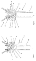
- FIGS 2 to 6 show different examples of syringe pumps 1 according to the present invention.
- Each syringe pump 1 has a syringe 11 which consists of a glass barrel 4 and a syringe plunger 12.
- Each syringe 11 is closed by a valve 15 that is mounted in a valve block 27.
- Two ports 33, 34 extend from the glass barrel 4, through the valve block 27 to connect the volume within the syringe pump 1 to a valve member 20.
- Two inlet/outlets 17, 18 are provided to introduce liquid into, and remove liquid from, the syringe 11. Liquid may be introduced through either inlet/outlet 17 or 18. Equally, liquid can exit through either inlet/outlet 17 or 18 depending on the valve position.
- Figure 2 shows a first syringe pump 1 with a valve 15 which has a two-port rotary valve member 20 through which a single passage in the form of a bore 16 extends.
- the bore 16 is offset from the rotational axis of the valve member 20. In use, it allows the flow of fluid into or out of the syringe 11.
- the off-axis positioning of the bore 16 allows the same bore to access, sequentially on rotation, inlet/outlet 17 and port 33 and then inlet/outlet 18 and port 34.
- a second syringe pump 1 shown in Figure 3 comprises, in addition to those features discussed above with regard to Figure 2, a second off-axis bore 21.
- the second bore 21 is at an acute angle to the first bore 16 in this example. This configuration of bores 16 and 21 enables the syringe 11 to be filled and emptied through separate bores thus ensuring that no air bubbles can remain in the syringe.
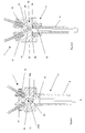
- the syringe pump 1 shown in Figure 4 has a similar valve configuration to that shown in Figure 3. However, instead of bores, the sides of the valve member 20 are cut away in order to form the fluid passages. These cutaway passages 16a, 21a are easier to manufacture than the bores 16, 21 described above.
- Figure 5 shows a valve 15 and associated ports 33, 34 configured for a syringe 11 with a narrow barrel 4 that would be too small to accommodate the arrangement of ports shown in Figure 4.
- the ports 33, 34 are non-parallel and join together at the point of entry of the ports into the barrel 4.
- FIG 6 shows a further syringe 11 in which the valve 15 has a single, bore 35 located on across the rotational axis of the valve member 20.
- This syringe 11 works in a similar manner to that shown in Figure 2 in that the bore 35 connects sequentially with the ports 33, 34 and the inlet/outlets 17, 18. However, as the bore 35 is axial it links the port 33 to the opposing inlet/outlet 18 or the port 34 to the inlet/outlet 17.
- valves 15 shown in Figures 2 to 6 are rotary valves. However, the skilled man would readily understand that the principles of the present invention could be implemented with a slide or shuttle valve or any other type of valve capable of interfacing with the other integers of the syringe pump 1 described above.
- Each of the syringe pumps 1 shown in Figures 2 to 6 can be retrofitted into a conventional syringe pump driver in place of the standard syringe pump shown in Figure 1.
- Figures 7A to 7E show the sequence of priming the syringe pump 1 comprising a rotary valve 15 as shown in Figure 4.
- Figure 7A shows the syringe 11 when it is not in use and the syringe 11 is empty of liquid.
- the cutaway section 16a is in contact with both the inlet port 17 and the syringe 11 through the port 33, whilst the cutaway portion 21a is in contact with the outlet port 18 only.
- the fluid 14 enters the syringe 11 through the inlet port 17, via the cutaway section 16a of the rotary valve 15. It will be evident from Figure 7B that air bubbles 13 may be in the syringe when the liquid 14 enters.
- Valve member 20 is then rotated through an intermediate state, wherein neither cutaway section is in contact with either of the ports 33, 34, and into the position shown in Figure 7C wherein the cutaway section 16a allows the syringe 11 to be used for dispensing via the outlet port 18.
- the air bubbles 13 move through the valve 15 ahead of the fluid and leave the syringe 11. This process may then be repeated with a water/alcohol mix in order to sterilise the liquid path.
- Figure 7D shows the syringe after re-filling with liquid 14 to be dispensed.
- the air bubbles 13 do not re-enter the syringe 11 and therefore do not introduce inconsistencies in the volume dispensed at some later time.
- Figure 7E shows the syringe pump 1 at the end of the priming sequence. All air has been purged from the syringe pump 1 and only liquid remains in the passageways 16.
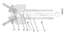
- Figures 8 and 9 show two different methods of attaching a syringe 11 to a valve block 27.
- a particular advantage of the syringe pump 1 of the present invention is that it can be retrofitted to an existing syringe pump driver in order to improve the system performance at minimum cost.
- Figure 8 shows the syringe 11 attached to the valve block 27 by a support block 38 in which the top end of the barrel is fixed, for example, by adhesive, and has a conventional screw-thread 28 engaging a complementary screw-thread in the valve block 27.
- Figure 9 shows a clamp plate 29 at the end of the syringe barrel 4 opposite the valve.
- the plate 29 and associated bolts 31 which screw into the valve block 27 apply pressure to the syringe barrel 4 which, in turn, compresses a seal 32 between the syringe barrel 4 and the valve block 27.
- the clamp plate 29 has the advantage that it provides far better visibility of the whole length of the syringe barrel 4, in use.
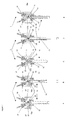
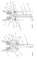
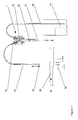
- Figures 10 and 11 show further detail of the syringe pump 1 in a dispensing assembly.
- Figure 10 shows a horizontally configured syringe pump1 and
- Figure 11 shows a vertically configured syringe pump 1.
- the inlet 17 leads, via liquid input tubing 22, to a liquid reservoir 23 containing a fluid 14 to be dispensed.
- the outlet 18 leads, via liquid output tubing 24, to a dispensing tip 25 from which fluid 14 is dispensed into a conventional multi-well microplate 26.
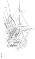
- a dispensing array can be formed from a plurality of dispensing assemblies as shown in Figure 12.
- the dispensing tips 25 of the dispensers are formed into a substantially parallel dispensing array and the inlets 17 are connected via a manifold 30 to the reservoir (not shown).
- the input and output tubing connecting each inlet/outlet 17, 18 to the manifold 30 and dispensing tip 25 has been omitted.
- the syringes 11 are also formed into a substantially parallel array such that the valve core is common across all syringe pumps 1 and syringe plungers 12 can be actuated simultaneously by an actuator moving in a plane perpendicular to the plane of the array of plungers 12.
Priority Applications (2)
| Application Number | Priority Date | Filing Date | Title |
|---|---|---|---|
| EP05107629A EP1754505A1 (de) | 2005-08-19 | 2005-08-19 | Spritzenpumpe |
| US11/503,409 US20070088289A1 (en) | 2005-08-19 | 2006-08-14 | Syringe pump |
Applications Claiming Priority (1)
| Application Number | Priority Date | Filing Date | Title |
|---|---|---|---|
| EP05107629A EP1754505A1 (de) | 2005-08-19 | 2005-08-19 | Spritzenpumpe |
Publications (1)
| Publication Number | Publication Date |
|---|---|
| EP1754505A1 true EP1754505A1 (de) | 2007-02-21 |
Family
ID=35695832
Family Applications (1)
| Application Number | Title | Priority Date | Filing Date |
|---|---|---|---|
| EP05107629A Ceased EP1754505A1 (de) | 2005-08-19 | 2005-08-19 | Spritzenpumpe |
Country Status (2)
| Country | Link |
|---|---|
| US (1) | US20070088289A1 (de) |
| EP (1) | EP1754505A1 (de) |
Cited By (7)
| Publication number | Priority date | Publication date | Assignee | Title |
|---|---|---|---|---|
| EP1970677A1 (de) | 2007-03-15 | 2008-09-17 | F. Hoffmann-La Roche AG | Dosiervorrichtung für ein Infusionssystem |
| EP2510961A1 (de) * | 2011-04-12 | 2012-10-17 | F. Hoffmann-La Roche AG | Infusionspumpenvorrichtung mit verbesserter Auffüllung des Flüssigkeitssystems und Verfahren zum Auffüllen einer solchen Infusionspumpenvorrichtung |
| WO2012140063A1 (en) | 2011-04-12 | 2012-10-18 | F. Hoffmann-La Roche Ag | Infusion pump device with re-filling scheme for cylinder - piston dosing unit |
| WO2012140052A1 (en) | 2011-04-12 | 2012-10-18 | F. Hoffmann-La Roche Ag | Infusion pump device with cylinder-piston dosing unit and optical piston position detection |
| US8469930B2 (en) | 2008-09-12 | 2013-06-25 | Roche Diagnostics International Ag | Dosing unit, ambulatory infusion device comprising dosing unit and method for operating a dosing unit |
| WO2014116368A1 (en) * | 2013-01-25 | 2014-07-31 | Acist Medical Systems, Inc. | Regulating flow paths in a medical injection system |
| EP2815778A1 (de) * | 2013-06-21 | 2014-12-24 | F. Hoffmann-La Roche AG | Tragbares Infusionsgerät für Kinder mit wiederbefüllbarer Dosiereinheit kleinen Volumeninhalts |
Families Citing this family (3)
| Publication number | Priority date | Publication date | Assignee | Title |
|---|---|---|---|---|
| US9057370B2 (en) * | 2008-08-08 | 2015-06-16 | Hamilton Company | Negative dead volume syringe |
| WO2010126622A1 (en) * | 2009-04-27 | 2010-11-04 | Animal Innovations, Inc. | Injection syringe plunger valve assembly |
| US11340104B2 (en) | 2020-07-07 | 2022-05-24 | Matthew Moers | Syringe with a valve in a housing for measuring chemicals |
Citations (7)
| Publication number | Priority date | Publication date | Assignee | Title |
|---|---|---|---|---|
| EP0269444A2 (de) * | 1986-11-26 | 1988-06-01 | Henry B. Kopf | Vorrichtung und Verfahren zum Massentransfer von biologisch-pharmazeutischen Medien |
| EP0345396A1 (de) * | 1987-12-04 | 1989-12-13 | Imed Corporation | IV-Pumpenkassette |
| US4904245A (en) * | 1988-12-07 | 1990-02-27 | Allen S. Chen | Surgical valve assembly for urinary bladder irrigation and drainage |
| US4967797A (en) * | 1989-08-16 | 1990-11-06 | Manska Wayne E | Tap valve |
| WO1997014027A2 (en) * | 1995-10-09 | 1997-04-17 | Takeda Chemical Industries, Ltd. | Injector |
| US5916201A (en) * | 1995-01-20 | 1999-06-29 | Wilson, Jr.; Roland B. | Anti-cross contamination valve and fluid delivery systems using same |
| EP1473054A1 (de) * | 2003-04-28 | 2004-11-03 | The Automation Partnership (Cambridge) Limited | Abgabevorrichtung |
Family Cites Families (6)
| Publication number | Priority date | Publication date | Assignee | Title |
|---|---|---|---|---|
| US1633074A (en) * | 1925-08-06 | 1927-06-21 | Mott Richard H De | Surgical device |
| US3048192A (en) * | 1957-08-14 | 1962-08-07 | Cordis Corp | Surgical valve |
| SE313197B (de) * | 1964-11-06 | 1969-08-04 | Atomenergi Ab | |
| US3626938A (en) * | 1970-06-30 | 1971-12-14 | Antonio A Versaci | Hemodialysis shunt valve device with body connecting means |
| US3837534A (en) * | 1972-10-16 | 1974-09-24 | Rohe Scientific Corp | Compact, flexible, multiple fluid dispenser |
| IT1244370B (it) * | 1991-01-11 | 1994-07-08 | Roerig Farmaceutici Italiana S | Dispositivo per il prelievo selettivo di campioni di sangue da due sezioni di una linea e per iniezione di farmaci nel sangue stesso |
-
2005
- 2005-08-19 EP EP05107629A patent/EP1754505A1/de not_active Ceased
-
2006
- 2006-08-14 US US11/503,409 patent/US20070088289A1/en not_active Abandoned
Patent Citations (7)
| Publication number | Priority date | Publication date | Assignee | Title |
|---|---|---|---|---|
| EP0269444A2 (de) * | 1986-11-26 | 1988-06-01 | Henry B. Kopf | Vorrichtung und Verfahren zum Massentransfer von biologisch-pharmazeutischen Medien |
| EP0345396A1 (de) * | 1987-12-04 | 1989-12-13 | Imed Corporation | IV-Pumpenkassette |
| US4904245A (en) * | 1988-12-07 | 1990-02-27 | Allen S. Chen | Surgical valve assembly for urinary bladder irrigation and drainage |
| US4967797A (en) * | 1989-08-16 | 1990-11-06 | Manska Wayne E | Tap valve |
| US5916201A (en) * | 1995-01-20 | 1999-06-29 | Wilson, Jr.; Roland B. | Anti-cross contamination valve and fluid delivery systems using same |
| WO1997014027A2 (en) * | 1995-10-09 | 1997-04-17 | Takeda Chemical Industries, Ltd. | Injector |
| EP1473054A1 (de) * | 2003-04-28 | 2004-11-03 | The Automation Partnership (Cambridge) Limited | Abgabevorrichtung |
Cited By (27)
| Publication number | Priority date | Publication date | Assignee | Title |
|---|---|---|---|---|
| US10034977B2 (en) | 2007-03-15 | 2018-07-31 | Roche Diabetes Care, Inc. | Dosing device for an infusion system and method thereof |
| EP3258223A1 (de) * | 2007-03-15 | 2017-12-20 | F. Hoffmann-La Roche AG | Dosiervorrichtung für ein infusionssystem |
| US7955302B2 (en) | 2007-03-15 | 2011-06-07 | Roche Diagnostics International Ltd. | Dosing device for an infusion system and method thereof |
| US8277423B2 (en) | 2007-03-15 | 2012-10-02 | Roche Diagnostics International Ag | Dosing device for an infusion system and method thereof |
| US8277434B2 (en) | 2007-03-15 | 2012-10-02 | Roche Diagnostics International Ag | Dosing device for an infusion system and method thereof |
| US10034983B2 (en) | 2007-03-15 | 2018-07-31 | Roche Diabetes Care, Inc. | Dosing device for an infusion system and method thereof |
| WO2008110263A1 (de) | 2007-03-15 | 2008-09-18 | F. Hoffmann-La Roche Ag | Dosiervorrichtung für ein infusionssystem |
| US10029046B2 (en) | 2007-03-15 | 2018-07-24 | Roche Diabetes Care, Inc. | Dosing device for an infusion system and method thereof |
| EP3012600A1 (de) * | 2007-03-15 | 2016-04-27 | F. Hoffmann-La Roche AG | Dosiervorrichtung für ein infusionssystem |
| EP1970677A1 (de) | 2007-03-15 | 2008-09-17 | F. Hoffmann-La Roche AG | Dosiervorrichtung für ein Infusionssystem |
| US9687604B2 (en) | 2007-03-15 | 2017-06-27 | Roche Diagnostics International Ag | Dosing device for an infusion system and method thereof |
| US8790316B2 (en) | 2007-03-15 | 2014-07-29 | Roche Diagnostics International Ag | Dosing device for an infusion system and method thereof |
| US8500700B2 (en) | 2008-09-12 | 2013-08-06 | Roche Diagnostics International Ag | Dosing unit, ambulatory infusion device comprising dosing unit and method for operating a dosing unit |
| US8469930B2 (en) | 2008-09-12 | 2013-06-25 | Roche Diagnostics International Ag | Dosing unit, ambulatory infusion device comprising dosing unit and method for operating a dosing unit |
| US9119911B2 (en) | 2008-09-12 | 2015-09-01 | Roche Diagnostics International Ag | Dosing unit, ambulatory infusion device comprising dosing unit and method for operating a dosing unit |
| US9402951B2 (en) | 2011-04-12 | 2016-08-02 | Roche Diagnostics International Ag | Infusion pump device and method for improved dosing |
| US9446193B2 (en) | 2011-04-12 | 2016-09-20 | Roche Diagnostics International Ag | Dosing unit for an infusion pump device |
| WO2012140056A1 (en) | 2011-04-12 | 2012-10-18 | F. Hoffmann-La Roche Ag | Infusion pump device with improved priming of the fluidic system and method for priming such an infusion pump device |
| WO2012140052A1 (en) | 2011-04-12 | 2012-10-18 | F. Hoffmann-La Roche Ag | Infusion pump device with cylinder-piston dosing unit and optical piston position detection |
| WO2012140063A1 (en) | 2011-04-12 | 2012-10-18 | F. Hoffmann-La Roche Ag | Infusion pump device with re-filling scheme for cylinder - piston dosing unit |
| EP2510961A1 (de) * | 2011-04-12 | 2012-10-17 | F. Hoffmann-La Roche AG | Infusionspumpenvorrichtung mit verbesserter Auffüllung des Flüssigkeitssystems und Verfahren zum Auffüllen einer solchen Infusionspumpenvorrichtung |
| US10525211B2 (en) | 2011-04-12 | 2020-01-07 | Roche Diabetes Care, Inc. | Infusion pump and method for improved filling of a fluidic system |
| CN104936650A (zh) * | 2013-01-25 | 2015-09-23 | 阿西斯特医疗系统有限公司 | 在医疗注射系统中调节流动路径 |
| US9067009B2 (en) | 2013-01-25 | 2015-06-30 | Acist Medical Systems, Inc. | Regulating flow paths in a medical injection system |
| WO2014116368A1 (en) * | 2013-01-25 | 2014-07-31 | Acist Medical Systems, Inc. | Regulating flow paths in a medical injection system |
| CN104936650B (zh) * | 2013-01-25 | 2018-01-16 | 阿西斯特医疗系统有限公司 | 在医疗注射系统中调节流动路径 |
| EP2815778A1 (de) * | 2013-06-21 | 2014-12-24 | F. Hoffmann-La Roche AG | Tragbares Infusionsgerät für Kinder mit wiederbefüllbarer Dosiereinheit kleinen Volumeninhalts |
Also Published As
| Publication number | Publication date |
|---|---|
| US20070088289A1 (en) | 2007-04-19 |
Similar Documents
| Publication | Publication Date | Title |
|---|---|---|
| EP1754505A1 (de) | Spritzenpumpe | |
| US7814805B2 (en) | Automated pipette machine | |
| US4946100A (en) | Liquid dispenser | |
| KR0160947B1 (ko) | 다중 포트로 유출시키는 펌프 | |
| US8535021B2 (en) | Precision pump with multiple heads | |
| JP2006145458A (ja) | 分注装置 | |
| US20110073620A1 (en) | Twisting translational displacement pump cartridge | |
| WO2006044468A2 (en) | Multiple port dual diameter pumps | |
| JPH09216698A (ja) | 分配装置 | |
| US8047815B2 (en) | Precision pump with multiple heads | |
| EP1510255A1 (de) | Mikrofluidisches System | |
| EP0796658A2 (de) | Gerät zur gleichzeitigen Absaugung und Abgabe von Fluiden | |
| US20100111721A1 (en) | Dual piston pump assembly with anti-rotation guide rails | |
| CN1309482C (zh) | 流体产品的分配泵 | |
| EP3419583B1 (de) | Mehrfachfluid-einspritzpumpe | |
| US20090016903A1 (en) | Precision Pump With Multiple Heads | |
| US20080118376A1 (en) | Translational displacement pump and bulk fluid re-supply system | |
| EP1473054B1 (de) | Abgabevorrichtung | |
| US20060097013A1 (en) | Dispenser | |
| CN111065466B (zh) | 具有零位移密封装置的流体分配器 | |
| US4681242A (en) | Solvent pump | |
| WO1985003555A1 (en) | Apparatus for use in the injection or application of a filling, binding or coating composition consisting of two components | |
| JPH1123583A (ja) | 試薬分注装置、及びこれに用いられる試薬シリンジ | |
| JP4919548B2 (ja) | プランジャポンプ | |
| CN219388081U (zh) | 一种组合式计量泵 |
Legal Events
| Date | Code | Title | Description |
|---|---|---|---|
| PUAI | Public reference made under article 153(3) epc to a published international application that has entered the european phase |
Free format text: ORIGINAL CODE: 0009012 |
|
| AK | Designated contracting states |
Kind code of ref document: A1 Designated state(s): AT BE BG CH CY CZ DE DK EE ES FI FR GB GR HU IE IS IT LI LT LU LV MC NL PL PT RO SE SI SK TR |
|
| AX | Request for extension of the european patent |
Extension state: AL BA HR MK YU |
|
| 17P | Request for examination filed |
Effective date: 20070817 |
|
| AKX | Designation fees paid |
Designated state(s): AT BE BG CH CY CZ DE DK EE ES FI FR GB GR HU IE IS IT LI LT LU LV MC NL PL PT RO SE SI SK TR |
|
| 17Q | First examination report despatched |
Effective date: 20080123 |
|
| STAA | Information on the status of an ep patent application or granted ep patent |
Free format text: STATUS: THE APPLICATION HAS BEEN REFUSED |
|
| 18R | Application refused |
Effective date: 20091204 |