EP1754409A1 - Adjustable deflector apparatus for crop residue from an axially arranged threshing system to a residue distribution system - Google Patents
Adjustable deflector apparatus for crop residue from an axially arranged threshing system to a residue distribution system Download PDFInfo
- Publication number
- EP1754409A1 EP1754409A1 EP06117968A EP06117968A EP1754409A1 EP 1754409 A1 EP1754409 A1 EP 1754409A1 EP 06117968 A EP06117968 A EP 06117968A EP 06117968 A EP06117968 A EP 06117968A EP 1754409 A1 EP1754409 A1 EP 1754409A1
- Authority
- EP
- European Patent Office
- Prior art keywords
- crop residue
- flow
- deflector
- distribution system
- crop
- Prior art date
- Legal status (The legal status is an assumption and is not a legal conclusion. Google has not performed a legal analysis and makes no representation as to the accuracy of the status listed.)
- Granted
Links
- 239000010908 plant waste Substances 0.000 title claims abstract description 136
- 238000009826 distribution Methods 0.000 title claims abstract description 65
- 230000001154 acute effect Effects 0.000 claims 1
- 235000013339 cereals Nutrition 0.000 description 7
- 239000000463 material Substances 0.000 description 7
- 241000209140 Triticum Species 0.000 description 3
- 235000021307 Triticum Nutrition 0.000 description 3
- 240000008042 Zea mays Species 0.000 description 3
- 235000005824 Zea mays ssp. parviglumis Nutrition 0.000 description 3
- 235000002017 Zea mays subsp mays Nutrition 0.000 description 3
- 235000005822 corn Nutrition 0.000 description 3
- 230000000694 effects Effects 0.000 description 3
- 239000012530 fluid Substances 0.000 description 3
- 241000196324 Embryophyta Species 0.000 description 2
- 239000012634 fragment Substances 0.000 description 2
- 239000010902 straw Substances 0.000 description 2
- 238000009827 uniform distribution Methods 0.000 description 2
- 241000209504 Poaceae Species 0.000 description 1
- 238000005299 abrasion Methods 0.000 description 1
- 239000003905 agrochemical Substances 0.000 description 1
- 238000010276 construction Methods 0.000 description 1
- 230000008021 deposition Effects 0.000 description 1
- 230000001627 detrimental effect Effects 0.000 description 1
- 238000007599 discharging Methods 0.000 description 1
- 239000003337 fertilizer Substances 0.000 description 1
- 239000010903 husk Substances 0.000 description 1
- 230000001788 irregular Effects 0.000 description 1
- 235000021374 legumes Nutrition 0.000 description 1
- 239000002184 metal Substances 0.000 description 1
- 239000000203 mixture Substances 0.000 description 1
- 235000015097 nutrients Nutrition 0.000 description 1
- 239000000126 substance Substances 0.000 description 1
- 238000003971 tillage Methods 0.000 description 1
- 230000007704 transition Effects 0.000 description 1
Images


Classifications
-
- A—HUMAN NECESSITIES
- A01—AGRICULTURE; FORESTRY; ANIMAL HUSBANDRY; HUNTING; TRAPPING; FISHING
- A01F—PROCESSING OF HARVESTED PRODUCE; HAY OR STRAW PRESSES; DEVICES FOR STORING AGRICULTURAL OR HORTICULTURAL PRODUCE
- A01F7/00—Threshing apparatus
- A01F7/02—Threshing apparatus with rotating tools
- A01F7/06—Threshing apparatus with rotating tools with axles in line with the feeding direction ; Axial threshing machines
- A01F7/067—Threshing apparatus with rotating tools with axles in line with the feeding direction ; Axial threshing machines with material-flow influencing means
Definitions
- the present invention relates generally to an apparatus for transitioning or redirecting a flow of crop residue from an axially arranged threshing or separating system of an agricultural combine so as to flow more centrally into a crop residue distribution system for distributing the residue onto a field, and more particularly, to an apparatus including a crop residue flow deflector which is adjustably positionable within a range of positions so as to be impinged to a desired extent by a flow of crop residue from an axially extending rotor and concave assembly, for transitioning or deflecting the flow to the residue distribution system for achieving desired or required operational characteristics such as a particular transverse location, pattern and/or evenness of crop residue distribution on a harvested field.
- Axially arranged rotary threshing or separating systems have long been in use in agricultural combines for threshing crops to separate grain from crop residue, also referred to as material other than grain (MOG).
- Such axially arranged systems typically include at least one cylindrical rotor rotated within a concave or cage, the rotor and surrounding concave being oriented so as to extend forwardly to rearwardly within the combine.
- crop material is fed or directed into a circumferential passage between the rotor and concave and is carried rearwardly therebetween by the rotation of the rotor along a generally helical path as grain is threshed from the crop material.
- the flow of crop residue or MOG remaining between the rotor and concave after threshing is typically discharged or expelled by the rotating rotor from a discharge opening at a rear end of the passage in a generally downward, or a downward and sideward direction in what is a continuation of the helical path of movement of the crop residue within the passage between the rotor and concave.
- the flow is typically discharged into a passage which extends downwardly and somewhat rearwardly into a crop residue distribution system located below and rearwardly of the rear end of the threshing system, and which typically includes a rotary beater or other apparatus which propels the crop residue rearwardly within a rear end of the combine for either discharge from the combine through a rear opening onto a field, or into a chopper and/or spreader mounted on the rear end operable for spreading the residue over a swath of a field.
- One factor which has been found to influence the ability of a chopper and/or spreader to distribute crop residue evenly or uniformly over a field is the transverse or side to side evenness of crop residue inflow into the chopper and/or spreader. That is, it has been found that the amount of crop residue infeed to one side of the chopper should be about equal to infeed to the other side to achieve even distribution over a field.
- the side to side infeed to the chopper/spreader has been found to be a function of the side to side distribution of crop residue infeed into the beater or other impeller of the crop residue distribution system from the threshing system.
- residue from different crops such as wheat and corn
- different rotor rotation speeds will typically be used for different crops.
- small grains such as wheat and other grasses will typically be threshed at a relatively high rotor speed, for instance, 600 to 1000 revolutions per minute (rpm), and produce residue containing a large volume of small stalks of straw
- corn will typically be threshed at a relatively slow rotor speed, for instance, less than 400 rpm, and produce crop residue containing a mixture of bulky stalk segments, cob fragments and large leaves.
- differences in plant maturity and weather conditions can affect size, moisture content, and other characteristics of crop residue so as to have varying flow and distribution characteristics.
- the transition of crop residue flow from the threshing system to the residue distribution system can vary.
- the side to side distribution of the flow into the rotating beater can vary, that is, flow to one side of the beater can be heavier than to the other side, such that the beater will propel more crop residue into one side of a chopper and/or spreader, resulting, in turn, in uneven crop residue distribution over a swath of a field.
- an agricultural combine comprising:
- the threshing system discharges a flow of crop residue through a rearwardly located, generally downwardly facing discharge opening, at least a portion of the flow being directed along an internal side of the combine defining a side of a passage extending downwardly and rearwardly to a crop residue distribution system of the combine.
- the deflector is disposed in the side of the passage in a position such that at least a portion of the downward crop residue flow will strike or impinge the deflector and be deflected thereby transversely by a desired amount, so as to extend in a desired manner through a more central region of the passage toward the crop residue distribution system.
- the adjusting mechanism is operable for moving the deflector in relation to the internal side of the combine for adjusting a desired parameter or parameters of the downwardly deflected flow, which can include, but are not limited to, a transverse location at which the flow will enter the crop residue system.
- the adjusting mechanism can be operated to move the deflector so as to direct more or less of the crop residue flow toward one of the sides of the crop residue distribution system, for feeding a corresponding greater or lesser amount of crop residue to a corresponding side of a chopper and/or spreader, for correcting or compensating for conditions such as wind drift and the like.
- the adjusting mechanism is operable for moving the deflector in a first transverse direction for moving or shifting a location at which the flow deflected by the deflector will flow into the crop residue system in that same direction, the adjusting mechanism also being operable for moving the deflector in a second transverse direction opposite the first transverse direction, for moving the location at which the flow deflected by the deflector will flow into the crop residue distribution system in the second transverse direction.
- the deflector includes an upper portion pivotally mounted in the combine adjacent to the internal side such that a lower portion extending downwardly from the upper portion is located in the path of at least a portion of the crop residue flow.
- the lower portion of the deflector can include a lower edge positioned to extend into or across a path of the crop residue flow, such that a portion of the flow above the lower edge will impinge or strike the deflector and be deflected downwardly thereby into a portion of the flow below the lower edge, for deflecting the lower flow downwardly in a desired manner into the crop residue distribution system.
- the adjusting mechanism can comprise a remotely controllable actuator, such as, but not limited to, a fluid cylinder, rotary or linear actuator, dashpot, solenoid, or other well known, commercially available actuator device, which can be controllable by a switch or other operator control, or an automatic control, such as a processor based control, for achieving one or more desired crop residue flow characteristics.
- a remotely controllable actuator such as, but not limited to, a fluid cylinder, rotary or linear actuator, dashpot, solenoid, or other well known, commercially available actuator device, which can be controllable by a switch or other operator control, or an automatic control, such as a processor based control, for achieving one or more desired crop residue flow characteristics.
- the deflector can have a desired shape, including, but not limited to, a generally flat shape, or a curved shape such as a concave or convex curved shape, as desired or required for a particular application.
- the lower edge of the deflector can be optionally straight or have an irregular shape, such as a bevelled shape, stepped shape, serrated shape, or a curved shape, such as a concave curved shape, or a convex curved shape, as desired or required.
- a range of positions of the deflector can include a position close to the interior side of the combine so as to have little or no effect on the flow, and a range of positions extending to a desired extent into and at a desired orientation in relation to all or a portion of the crop residue flow, for achieving a desired redirecting effect on the flow.
- a representative agricultural combine 20 including an axially arranged threshing system 22; a crop residue distribution system 24; and a crop residue chopper/spreader 26, all of well known construction and operation.
- threshing system 22 is axially arranged in that it includes a cylindrical rotor 28 conventionally supported and rotatable in a predetermined direction, denoted by arrow A in Figure 2, about a rotational axis 30 therethrough and within a concave 32, for conveying a flow of crop material in a helical flow path through a space 34 extending circumferentially around an outer cylindrical surface of rotor 28 and an inner circumferential surface of concave 32.
- the crop such as grain, legumes, or the like, will be loosened and separated from crop residue such as straw, husk and pods, and carried away therefrom in the well known conventional manner.
- the crop residue will continue along a helical path through space 34, and will be expelled therefrom, as denoted by arrows B, through a discharge opening 36, which essentially comprises an extension of space 34, located adjacent to the rear right side of rotor 28.
- Some of the flow expelled through opening 36 will tend to be directed more downwardly, as denoted by arrow B on the right hand side of Figure 2, so as to flow generally downwardly along internal side 38, while some portions of the flow will be directed and/or be carried by rotating rotor 28 and momentum, in a transverse direction, denoted by arrows C in Figure 2, toward an opposite internal side of combine 20, and will eventually flow downwardly toward crop residue distribution system 24, as denoted by arrows C1.
- the consistency of the flow of crop residue, volume thereof, and extent or pattern thereof, will typically vary, and be a function of a variety of conditions, including, but not limited to, a speed of rotation in direction A of rotor 28, crop type, plant maturity, moisture content, and weather conditions.
- rotor speeds can vary between just a few hundred rpm and over a thousand rpm.
- Wheat and other small grains will typically have relatively small crop residue components, whereas other grains, such as corn, will typically have larger components, such as thick stalk segments, cob fragments, and large leaves.
- the downward flow of crop residue will be more to a right hand side of a front-to-rear extending vertical centreline 40 of both threshing system 22 and crop residue distribution system 24.
- extent D The sideward extent of such typical downward flow is represented by extent D in Figure 2, and is generally bounded on the left hand side by a line 42 extending generally downwardly on the left of centreline 40, and on the right hand side by a line 44 extending generally downwardly from internal side 38, the sideward or transverse location of line 42 and thus the transverse extent D of the downward flow varying as a function of one or more of the above conditions and/or parameters.
- crop residue distribution system 24 will typically include a rotary device, such as a beater 46 (see Figure 3), rotatable in a direction E above a concave pan 48.
- Beater 46 typically rotates at a rapid speed, so as to be capable of accelerating and propelling a flow of crop residue rearwardly within the confines of the rear end of combine 20, as generally denoted by arrows F.
- Such rearward flow is typically guided and directed by internal panels or shields, generally denoted by shields 50 ( Figure 1), so as to either flow into a crop residue chopper and/or spreader, such as chopper/spreader 26, or through a rear opening so as to be deposited directly onto a field.
- a chopper and/or spreader such as a chopper/spreader 26 will be operated so as to distribute the crop residue in a layer on a strip of a field being harvested by combine 20.
- a chopper and/or spreader such as a chopper/spreader 26 will be operated so as to distribute the crop residue in a layer on a strip of a field being harvested by combine 20.
- the present invention provides for an adjustable deflector apparatus 52 disposed in the path of at least a portion of the crop residue flow B. More particularly, deflector apparatus 52 is preferably located in a position such that at least portions of any crop residue flow B which would flow along or close to side 38, will instead impinge or strike deflector apparatus 52 and be deflected downwardly thereby, as denoted by arrow B1 in Figures 2 and 6, and arrows B2 in Figure 5.
- the downwardly directed crop residue flow will be transversely shifted or moved in a transverse direction, that is, more to the left of internal side 38, depending on the transverse position and orientation of deflector apparatus 52.
- a transverse direction that is, more to the left of internal side 38, depending on the transverse position and orientation of deflector apparatus 52.
- the transverse position or location of crop residue inflow can be adjusted, for example, to be aligned with a vertical centreline of the distribution system, such as centreline 40, which is a joint centreline of rotor 28 of threshing system 22 and beater 46 of distribution system 24, as illustrated by the location of the centre of transverse extent D1 in Figure 2.
- deflector apparatus 52 is preferably pivotally mounted to combine 20 for pivotal movement through a range of positions, such as represented by the positions shown in Figures 5 and 6.
- Deflector apparatus 52 is preferably constructed of a rigid, abrasion resistant material, such as sheet metal or the like, and includes an upper end portion 58 mounted at a suitable location, such as on internal side 38 as best shown in Figure 2, which can comprise a portion of concave 32, or be located in the vicinity thereof.
- Deflector apparatus 52 additionally includes a lower end portion 60 which extends downwardly from upper end portion 58 and is positioned in the path of at least a portion of the flow B of crop residue, so as to be impinged or struck by the flow B for deflecting it downwardly in the above-described manner.
- upper end portion 58 preferably includes a pair of pivot arms 62 which extend through appropriate passages in internal side 38 and pivotally connect with an actuator 64 operable for effecting pivotal movement of deflector apparatus 52 through a range of positions between about those shown in Figures 5 and 6.
- Actuator 64 is preferably located external to threshing system 22 so as to be outside of the path of the crop residue flow.
- Actuator 64 can be any suitable commercially available actuator device and is preferably remotely controllable, such as using a switch or other control in an operator cab of combine 20, or it can be controlled automatically such as by a processor based controller or the like (not shown), for effecting desired pivotal movements of deflector apparatus 52.
- Actuator 64 can comprise any suitable actuator device, such as a fluid cylinder, a linear actuator, such as a dashpot or solenoid, a rotary actuator, or the like, operable for effecting the desired movements.
- actuator 64 is depicted as a fluid cylinder including a rod 66 having an end pivotally connected to pivot arms 62 in a suitable manner, such as using a pin 68 ( Figure 4) which can be extended through aligned holes in pivot arms 62 and rod 66, and secured therein in a suitable manner, such as using a cotter pin 70, in the well known manner.
- crop residue flow characteristics from an axially arranged threshing system 22 of a combine 20, into a crop residue distribution system 24, and from there, into and from a crop residue chopper/spreader 26, are illustrated.
- flow D from threshing system 22 is centred about a centreline 72 which is offset from centreline 40 of threshing system 22.
- crop residue flow F propelled rearwardly by crop residue distribution system 24 is similarly offset in the same direction and centred about centreline 72.
- Flow F flows into crop residue chopper/spreader 26 in the offset manner, and chopper/spreader 26, in turn, propels the crop residue from the rear end of combine 20 in a similarly offset manner, as illustrated by large arrow G.
- the crop residue will be spread unevenly over a swath of the field.
- combine 20 is shown including axially arranged threshing system 22 and adjustable deflector apparatus 52 as explained above, but differs in that it illustrates utility of adjustable deflector apparatus 52 in association with a crop residue distribution system 24 including a rotary chopper 74 instead of beater 46.
- the effect is the same, the shift of the infeed of crop residue flow as effected by deflector apparatus 52 is illustrated by arrow D1, centred about centreline 40, such that discharge from distribution system 24 is also centred along centreline 40, as illustrated by arrow F1.
- a different embodiment of a crop residue chopper/spreader 26 is illustrated, including a pair of impellers rotatable about horizontal axes for discharging crop residue in opposite sideward directions, as illustrated by arrows H.
- the centred flow of crop residue F1 from distribution system 24 and into chopper/spreader 26, results in more even inflow into chopper/spreader 26, such that outflows H will be more even, resulting in more uniform spreading characteristics.
- a representative swath on a field strip 76 is shown, including a centreline 78 which will correspond in location to centreline 40 of combine 20 illustrated in the above figures.
- a representative distribution of crop residue without use of adjustable deflector apparatus 52 is shown by hidden line 80, and illustrates a heavier distribution of crop residue to the right hand side of centreline 78.
- Phantom line 82 is level and even across the extent of strip 76, and illustrates an even, uniform distribution of crop residue over a swath, such as a swath 82, utilizing the present invention, including deflector apparatus 52 in the above-described manner.
- FIGs 11 and 12 illustrate alternative embodiments of adjustable deflector apparatus 52.
- apparatus 52 includes an alternative lower end portion 84 including a tapered lower edge portion 86.
- apparatus 52 is shown including a curved surface 90 between upper end portion 58 and lower end portion 88.
Landscapes
- Life Sciences & Earth Sciences (AREA)
- Environmental Sciences (AREA)
- Threshing Machine Elements (AREA)
- Outside Dividers And Delivering Mechanisms For Harvesters (AREA)
- Harvester Elements (AREA)
Abstract
Description
- The present invention relates generally to an apparatus for transitioning or redirecting a flow of crop residue from an axially arranged threshing or separating system of an agricultural combine so as to flow more centrally into a crop residue distribution system for distributing the residue onto a field, and more particularly, to an apparatus including a crop residue flow deflector which is adjustably positionable within a range of positions so as to be impinged to a desired extent by a flow of crop residue from an axially extending rotor and concave assembly, for transitioning or deflecting the flow to the residue distribution system for achieving desired or required operational characteristics such as a particular transverse location, pattern and/or evenness of crop residue distribution on a harvested field.
- Axially arranged rotary threshing or separating systems have long been in use in agricultural combines for threshing crops to separate grain from crop residue, also referred to as material other than grain (MOG). Such axially arranged systems typically include at least one cylindrical rotor rotated within a concave or cage, the rotor and surrounding concave being oriented so as to extend forwardly to rearwardly within the combine.
- In operation, crop material is fed or directed into a circumferential passage between the rotor and concave and is carried rearwardly therebetween by the rotation of the rotor along a generally helical path as grain is threshed from the crop material. The flow of crop residue or MOG remaining between the rotor and concave after threshing is typically discharged or expelled by the rotating rotor from a discharge opening at a rear end of the passage in a generally downward, or a downward and sideward direction in what is a continuation of the helical path of movement of the crop residue within the passage between the rotor and concave.
- The flow is typically discharged into a passage which extends downwardly and somewhat rearwardly into a crop residue distribution system located below and rearwardly of the rear end of the threshing system, and which typically includes a rotary beater or other apparatus which propels the crop residue rearwardly within a rear end of the combine for either discharge from the combine through a rear opening onto a field, or into a chopper and/or spreader mounted on the rear end operable for spreading the residue over a swath of a field.
- When spread in a swath over a field, it is desirable in many instances for the crop residue to be distributed evenly or uniformly over the swath. This is desirable for reasons including that uneven crop residue distribution on a field can lead to temperature and moisture gradients detrimental to even growth of future crops on the field. It can also make it difficult for crops to utilize nutrients, and can impact the effectiveness of agricultural chemicals. Large discontinuities of crop residue can lead to plugging and other functional problems with tillage and/or planting equipment.
- One factor which has been found to influence the ability of a chopper and/or spreader to distribute crop residue evenly or uniformly over a field is the transverse or side to side evenness of crop residue inflow into the chopper and/or spreader. That is, it has been found that the amount of crop residue infeed to one side of the chopper should be about equal to infeed to the other side to achieve even distribution over a field. In turn, the side to side infeed to the chopper/spreader has been found to be a function of the side to side distribution of crop residue infeed into the beater or other impeller of the crop residue distribution system from the threshing system.
- Numerous devices and structures have been developed to improve flow of crop residue from axially arranged threshing systems into crop residue distribution systems. Reference in this regard is made to
US-B-6,352,474 andUS-B-6,241,605 . - Although the above referenced apparatus may perform well, it has been found that a variety of variables and conditions can influence the ability to redirect and transversely distribute crop residue flow in the passage between a threshing system and a crop residue distribution system.
- For instance, residue from different crops, such as wheat and corn, will typically flow differently, and different rotor rotation speeds will typically be used for different crops. For instance, small grains such as wheat and other grasses will typically be threshed at a relatively high rotor speed, for instance, 600 to 1000 revolutions per minute (rpm), and produce residue containing a large volume of small stalks of straw, and, whereas corn will typically be threshed at a relatively slow rotor speed, for instance, less than 400 rpm, and produce crop residue containing a mixture of bulky stalk segments, cob fragments and large leaves. For a given crop, differences in plant maturity and weather conditions can affect size, moisture content, and other characteristics of crop residue so as to have varying flow and distribution characteristics.
- As a result of the above described variables and conditions, it has been observed that the transition of crop residue flow from the threshing system to the residue distribution system can vary. In particular, the side to side distribution of the flow into the rotating beater can vary, that is, flow to one side of the beater can be heavier than to the other side, such that the beater will propel more crop residue into one side of a chopper and/or spreader, resulting, in turn, in uneven crop residue distribution over a swath of a field.
- Thus, what is sought is an apparatus for transitioning crop residue from an axially arranged threshing system of a combine to a distribution system, that overcomes one or more of the problems and disadvantages set forth above.
- According to the invention there is provided an agricultural combine comprising:
- an axially arranged threshing system including a rotor rotatable within a concave and having adjacent its rear end a discharge opening for expelling therethrough a flow of crop residue;
- a crop residue distribution system disposed for receiving said flow of crop residue from the threshing system; and
- a deflector disposed in the path of the flow of crop residue from the threshing system such that at least a portion of the flow will strike the deflector and be deflected thereby toward the crop residue distribution system,
- an adjusting mechanism operable for moving the deflector for adjusting a transverse location at which the flow portion deflected by the deflector will enter the crop residue distribution system.
- According to a preferred aspect of the invention, the threshing system discharges a flow of crop residue through a rearwardly located, generally downwardly facing discharge opening, at least a portion of the flow being directed along an internal side of the combine defining a side of a passage extending downwardly and rearwardly to a crop residue distribution system of the combine.
- The deflector is disposed in the side of the passage in a position such that at least a portion of the downward crop residue flow will strike or impinge the deflector and be deflected thereby transversely by a desired amount, so as to extend in a desired manner through a more central region of the passage toward the crop residue distribution system. The adjusting mechanism is operable for moving the deflector in relation to the internal side of the combine for adjusting a desired parameter or parameters of the downwardly deflected flow, which can include, but are not limited to, a transverse location at which the flow will enter the crop residue system. As a result, heavier inflow of crop residue into a side of the crop residue distribution system closer to the internal side of the combine to which the flow is directed can be transversely redirected, so as to provide better side-to-side or transverse distribution of the crop residue flow into the crop residue distribution system. As a consequence, the crop residue distribution system will be better able to feed the crop residue more evenly into a chopper and/or spreader located on the rear end of the combine, resulting in more even and uniform distribution of the crop residue over a swath of a field from which the crop has been harvested.
- As another alternative, the adjusting mechanism can be operated to move the deflector so as to direct more or less of the crop residue flow toward one of the sides of the crop residue distribution system, for feeding a corresponding greater or lesser amount of crop residue to a corresponding side of a chopper and/or spreader, for correcting or compensating for conditions such as wind drift and the like.
- According to another preferred aspect of the invention, the adjusting mechanism is operable for moving the deflector in a first transverse direction for moving or shifting a location at which the flow deflected by the deflector will flow into the crop residue system in that same direction, the adjusting mechanism also being operable for moving the deflector in a second transverse direction opposite the first transverse direction, for moving the location at which the flow deflected by the deflector will flow into the crop residue distribution system in the second transverse direction.
- According to another preferred aspect of the invention, the deflector includes an upper portion pivotally mounted in the combine adjacent to the internal side such that a lower portion extending downwardly from the upper portion is located in the path of at least a portion of the crop residue flow. Further, the lower portion of the deflector can include a lower edge positioned to extend into or across a path of the crop residue flow, such that a portion of the flow above the lower edge will impinge or strike the deflector and be deflected downwardly thereby into a portion of the flow below the lower edge, for deflecting the lower flow downwardly in a desired manner into the crop residue distribution system.
- To facilitate such operation, the adjusting mechanism can comprise a remotely controllable actuator, such as, but not limited to, a fluid cylinder, rotary or linear actuator, dashpot, solenoid, or other well known, commercially available actuator device, which can be controllable by a switch or other operator control, or an automatic control, such as a processor based control, for achieving one or more desired crop residue flow characteristics.
- According to still another preferred aspect of the invention, the deflector can have a desired shape, including, but not limited to, a generally flat shape, or a curved shape such as a concave or convex curved shape, as desired or required for a particular application. Additionally, the lower edge of the deflector can be optionally straight or have an irregular shape, such as a bevelled shape, stepped shape, serrated shape, or a curved shape, such as a concave curved shape, or a convex curved shape, as desired or required.
- According to another preferred aspect of the invention, a range of positions of the deflector can include a position close to the interior side of the combine so as to have little or no effect on the flow, and a range of positions extending to a desired extent into and at a desired orientation in relation to all or a portion of the crop residue flow, for achieving a desired redirecting effect on the flow.
- Preferred embodiments of the invention will now be described in further detail, by way of example only, with reference to the accompanying drawings, in which:
- Figure 1 is simplified schematic side view of agricultural combine, illustrating in dotted lines an axially arranged threshing system of the combine, and an adjustable deflector apparatus for transitioning crop residue flow from the threshing system to a residue distribution system of the combine;
- Figure 2 is a simplified schematic rear view of the threshing system and deflector apparatus of Figure 1, illustrating in phantom a path of crop residue flow expelled from the threshing system, and an adjusted path of the flow as effected by the deflector;
- Figure 3 is a simplified schematic side view of the threshing system, deflector, and crop residue distribution system;
- Figure 4 is a fragmentary perspective view of one embodiment of a deflector, illustrating connection thereof with an actuator operable for adjustably moving the deflector;
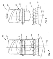
- Figure 5 is a simplified schematic rear view of the threshing system, deflector, and residue distribution system, showing the deflector in a generally upstanding position beside a side of the combine;
- Figure 6 is another simplified schematic rear end view of the threshing system, deflector and residue distribution system, showing the deflector at an alternative position in relation to the side of the combine;
- Figure 7 is a simplified schematic top view of a rear end of the combine, showing the threshing system, crop residue distribution system, and a crop residue chopper/spreader apparatus of the combine, and illustrating crop residue flow through the rear end of the combine and a relationship of crop residue discharged from the combine in relation to an axial centreline thereof;
- Figure 8 is another simplified schematic top view of the combine, showing the threshing system, deflector apparatus, residue distribution system and chopper/spreader apparatus, illustrating alignment of crop residue flow with an axial centreline as the result of the present invention;
- Figure 9 is still another simplified schematic top view of the combine, showing the threshing system, deflector apparatus, and an alternative residue distribution system and spreader apparatus, illustrating alignment of crop residue flow with an axial centreline of the combine resulting from the present invention;
- Figure 10 is a simplified schematic representation of a swath of a field, showing in dotted lines a representative pattern of crop residue distribution over the swath without the invention, and in phantom a pattern of crop residue distribution over the swath as effected by the deflector apparatus of the invention;
- Figure 11 is a perspective view of an alternative embodiment of a deflector according to the invention; and
- Figure 12 is a perspective view of another alternative deflector apparatus of the invention.
- In Figure 1, a representative
agricultural combine 20 is shown, including an axially arrangedthreshing system 22; a cropresidue distribution system 24; and a crop residue chopper/spreader 26, all of well known construction and operation. - Referring also to Figures 2 and 3, essentially,
threshing system 22 is axially arranged in that it includes acylindrical rotor 28 conventionally supported and rotatable in a predetermined direction, denoted by arrow A in Figure 2, about arotational axis 30 therethrough and within a concave 32, for conveying a flow of crop material in a helical flow path through aspace 34 extending circumferentially around an outer cylindrical surface ofrotor 28 and an inner circumferential surface of concave 32. As the crop material is moved throughspace 34, the crop, such as grain, legumes, or the like, will be loosened and separated from crop residue such as straw, husk and pods, and carried away therefrom in the well known conventional manner. - The crop residue will continue along a helical path through
space 34, and will be expelled therefrom, as denoted by arrows B, through adischarge opening 36, which essentially comprises an extension ofspace 34, located adjacent to the rear right side ofrotor 28. Some of the flow expelled throughopening 36 will tend to be directed more downwardly, as denoted by arrow B on the right hand side of Figure 2, so as to flow generally downwardly alonginternal side 38, while some portions of the flow will be directed and/or be carried by rotatingrotor 28 and momentum, in a transverse direction, denoted by arrows C in Figure 2, toward an opposite internal side ofcombine 20, and will eventually flow downwardly toward cropresidue distribution system 24, as denoted by arrows C1. - The consistency of the flow of crop residue, volume thereof, and extent or pattern thereof, will typically vary, and be a function of a variety of conditions, including, but not limited to, a speed of rotation in direction A of
rotor 28, crop type, plant maturity, moisture content, and weather conditions. As an example, rotor speeds can vary between just a few hundred rpm and over a thousand rpm. Wheat and other small grains will typically have relatively small crop residue components, whereas other grains, such as corn, will typically have larger components, such as thick stalk segments, cob fragments, and large leaves. Typically, the downward flow of crop residue will be more to a right hand side of a front-to-rear extendingvertical centreline 40 of boththreshing system 22 and cropresidue distribution system 24. The sideward extent of such typical downward flow is represented by extent D in Figure 2, and is generally bounded on the left hand side by aline 42 extending generally downwardly on the left ofcentreline 40, and on the right hand side by aline 44 extending generally downwardly frominternal side 38, the sideward or transverse location ofline 42 and thus the transverse extent D of the downward flow varying as a function of one or more of the above conditions and/or parameters. - Here, it should be noted that crop
residue distribution system 24 will typically include a rotary device, such as a beater 46 (see Figure 3), rotatable in a direction E above aconcave pan 48.Beater 46 typically rotates at a rapid speed, so as to be capable of accelerating and propelling a flow of crop residue rearwardly within the confines of the rear end ofcombine 20, as generally denoted by arrows F. Such rearward flow is typically guided and directed by internal panels or shields, generally denoted by shields 50 (Figure 1), so as to either flow into a crop residue chopper and/or spreader, such as chopper/spreader 26, or through a rear opening so as to be deposited directly onto a field. - Typically, a chopper and/or spreader, such as a chopper/
spreader 26 will be operated so as to distribute the crop residue in a layer on a strip of a field being harvested bycombine 20. As noted above, it is often desirable for the crop residue to be distributed evenly or uniformly over the swath, for a variety of purposes, important among which is uniform emergence of subsequently planted crops, and uniform application of chemicals and fertilizers onto the field. - As also noted above, it has been found in this regard that heavier flow of crop residue into one side or the other of crop
residue distribution system 24 will result in that system propelling more crop residue toward a corresponding side of a spreader apparatus, such as chopper/spreader 26, with a result of a heavier layer or distribution of crop residue on a corresponding side of a swath over a field. For the reasons set forth above, such uneven deposition of crop residue on a field is undesirable in many instances. - Referring also to Figures 4, 5 and 6, to overcome this problem, and provide the ability to adjust the side-to-side or transverse extent and location of crop residue flow into the crop residue distribution system of a combine, such as
system 24 ofcombine 20, the present invention provides for anadjustable deflector apparatus 52 disposed in the path of at least a portion of the crop residue flow B. More particularly,deflector apparatus 52 is preferably located in a position such that at least portions of any crop residue flow B which would flow along or close toside 38, will instead impinge or strikedeflector apparatus 52 and be deflected downwardly thereby, as denoted by arrow B1 in Figures 2 and 6, and arrows B2 in Figure 5. - Importantly, the downwardly directed crop residue flow, as illustrated by representative arrows B1 and B2, will be transversely shifted or moved in a transverse direction, that is, more to the left of
internal side 38, depending on the transverse position and orientation ofdeflector apparatus 52. Here, comparing Figure 5 to Figures 2 and 6, it is apparent that thefarther deflector apparatus 52 is moved transversely away fromside 38, the farther the downwardly directed crop residue flow is shifted in the transverse direction. - Studying Figure 2 more particularly, it should be noted and understood that the transverse movement or shifting of downwardly directed flow B1 causes a corresponding transverse shift of other portions of the downwardly directed flow in the transverse direction, as illustrated by arrows C1. Thus, it has been found that the overall transverse extent of the downward flow of crop residue, denoted by extent D1, extending between
lines deflector apparatus 52, in the path of portions of flow B in the vicinity ofinternal side 38 of the combine. - Thus, for a combine including a crop residue distribution system, such as
system 24 including arotary beater 46, the transverse position or location of crop residue inflow can be adjusted, for example, to be aligned with a vertical centreline of the distribution system, such ascentreline 40, which is a joint centreline ofrotor 28 of threshingsystem 22 andbeater 46 ofdistribution system 24, as illustrated by the location of the centre of transverse extent D1 in Figure 2. - To enable effecting adjusting movements of
deflector apparatus 52 for such purposes as effecting a transverse shift in overall crop residue flow,deflector apparatus 52 is preferably pivotally mounted to combine 20 for pivotal movement through a range of positions, such as represented by the positions shown in Figures 5 and 6.Deflector apparatus 52 is preferably constructed of a rigid, abrasion resistant material, such as sheet metal or the like, and includes anupper end portion 58 mounted at a suitable location, such as oninternal side 38 as best shown in Figure 2, which can comprise a portion of concave 32, or be located in the vicinity thereof. -
Deflector apparatus 52 additionally includes alower end portion 60 which extends downwardly fromupper end portion 58 and is positioned in the path of at least a portion of the flow B of crop residue, so as to be impinged or struck by the flow B for deflecting it downwardly in the above-described manner. To facilitate pivotal movement ofdeflector apparatus 52 relative tointernal side 38,upper end portion 58 preferably includes a pair ofpivot arms 62 which extend through appropriate passages ininternal side 38 and pivotally connect with anactuator 64 operable for effecting pivotal movement ofdeflector apparatus 52 through a range of positions between about those shown in Figures 5 and 6. -
Actuator 64 is preferably located external to threshingsystem 22 so as to be outside of the path of the crop residue flow.Actuator 64 can be any suitable commercially available actuator device and is preferably remotely controllable, such as using a switch or other control in an operator cab ofcombine 20, or it can be controlled automatically such as by a processor based controller or the like (not shown), for effecting desired pivotal movements ofdeflector apparatus 52.Actuator 64 can comprise any suitable actuator device, such as a fluid cylinder, a linear actuator, such as a dashpot or solenoid, a rotary actuator, or the like, operable for effecting the desired movements. Here,actuator 64 is depicted as a fluid cylinder including arod 66 having an end pivotally connected to pivotarms 62 in a suitable manner, such as using a pin 68 (Figure 4) which can be extended through aligned holes inpivot arms 62 androd 66, and secured therein in a suitable manner, such as using acotter pin 70, in the well known manner. - Referring to Figure 7, crop residue flow characteristics from an axially arranged threshing
system 22 of acombine 20, into a cropresidue distribution system 24, and from there, into and from a crop residue chopper/spreader 26, are illustrated. Here, it can be observed that flow D from threshingsystem 22 is centred about acentreline 72 which is offset fromcentreline 40 of threshingsystem 22. As a result, crop residue flow F propelled rearwardly by cropresidue distribution system 24 is similarly offset in the same direction and centred aboutcentreline 72. Flow F flows into crop residue chopper/spreader 26 in the offset manner, and chopper/spreader 26, in turn, propels the crop residue from the rear end ofcombine 20 in a similarly offset manner, as illustrated by large arrow G. As a result, the crop residue will be spread unevenly over a swath of the field. - Referring also to Figure 8, in contrast, utilizing
adjustable deflector apparatus 52 in association with threshingsystem 22 ofcombine 20, for deflecting crop residue flow D1 into a cropresidue distribution system 24 in a more centred manner, will result in a discharge of crop residue fromdistribution system 22 more centred in relation tocentreline 40, as illustrated by the location of the centre of arrow F1, so as to be inducted into chopper/spreader 26 in a more centred manner, and so as to be propelled from the rear end ofcombine 20 in more centred relation tocentreline 40, as illustrated by arrow G1. - Referring also to Figure 9, combine 20 is shown including axially arranged threshing
system 22 andadjustable deflector apparatus 52 as explained above, but differs in that it illustrates utility ofadjustable deflector apparatus 52 in association with a cropresidue distribution system 24 including arotary chopper 74 instead ofbeater 46. The effect is the same, the shift of the infeed of crop residue flow as effected bydeflector apparatus 52 is illustrated by arrow D1, centred aboutcentreline 40, such that discharge fromdistribution system 24 is also centred alongcentreline 40, as illustrated by arrow F1. - A different embodiment of a crop residue chopper/
spreader 26 is illustrated, including a pair of impellers rotatable about horizontal axes for discharging crop residue in opposite sideward directions, as illustrated by arrows H. Again, the centred flow of crop residue F1 fromdistribution system 24 and into chopper/spreader 26, results in more even inflow into chopper/spreader 26, such that outflows H will be more even, resulting in more uniform spreading characteristics. - Referring also to Figure 10, a representative swath on a
field strip 76 is shown, including acentreline 78 which will correspond in location to centreline 40 ofcombine 20 illustrated in the above figures. A representative distribution of crop residue without use ofadjustable deflector apparatus 52 is shown by hiddenline 80, and illustrates a heavier distribution of crop residue to the right hand side ofcentreline 78.Phantom line 82 is level and even across the extent ofstrip 76, and illustrates an even, uniform distribution of crop residue over a swath, such as aswath 82, utilizing the present invention, includingdeflector apparatus 52 in the above-described manner. - Figures 11 and 12 illustrate alternative embodiments of
adjustable deflector apparatus 52. In Figure 11,apparatus 52 includes an alternativelower end portion 84 including a taperedlower edge portion 86. In Figure 12,apparatus 52 is shown including acurved surface 90 betweenupper end portion 58 andlower end portion 88. These alternative embodiments illustrate the adaptability ofdeflector apparatus 52 for achieving a variety of crop residue flow characteristics that may be desired or required for a particular application. - It will be understood that changes in the details, materials, steps, and arrangements of parts which have been described and illustrated to explain the nature of the invention will occur to and may be made by those skilled in the art upon a reading of this disclosure within the principles and scope of the invention as defined by the claims. The foregoing description illustrates preferred embodiments of the invention; however, concepts, as based upon the description, may be employed in other embodiments without departing from said scope of the invention. Accordingly, the following claims are intended to protect the invention broadly as well as in the specific form shown.
Claims (9)
- An agricultural combine (20) comprising:an axially arranged threshing system (22) including a rotor (28) rotatable within a concave (32) and having adjacent its rear end a discharge opening (36) for expelling therethrough a flow (B) of crop residue;a crop residue distribution system (24) disposed for receiving said flow (B) of crop residue from the threshing system (22); anda deflector (52) disposed in the path of the flow (B) of crop residue from the threshing system such that at least a portion of the flow (B) will strike the deflector (52) and be deflected thereby toward the crop residue distribution system (24),characterised in that the combine (20) further comprises:an adjusting mechanism (62, 64, 66) operable for moving the deflector (52) for adjusting a transverse location (D) at which the flow portion (C) deflected by the deflector (52) will enter the crop residue distribution system (24).
- An agricultural combine according to claim 1, characterised in that:the discharge opening is a rearwardly located downwardly facing discharge opening (36) for downward flow (B) of crop residue along an internal side (38) defining a passage extending downwardly and rearwardly to the crop residue distribution system (24);the deflector (52) is disposed adjacent to the internal side (38) in a position such that at least a portion of the flow (B) is deflected thereby downwardly and transversely through the passage toward the crop residue distribution system (24); andthe adjusting mechanism (62, 64, 66) is operable for moving the deflector (52) in relation to the internal side (38).
- An agricultural combine according to claim 1 or 2, characterised in that the adjusting mechanism (62, 64, 66) is operable for moving the deflector (52) in a transverse direction for moving the location (D) at which the flow deflected by the deflector (52) will flow into the crop residue distribution system (24) in a corresponding transverse direction.
- An agricultural combine according to any of the preceding claims, characterised in that the deflector (52) includes an upper portion (58) and a lower portion (60/84/88), the upper portion (58) being pivotally mounted in the combine (20) such that at least the lower portion is located in the path of the flow (B).
- An agricultural combine according to claim 4, characterised in that the lower portion (84) of the deflector (52) includes a tapered lower edge (86), which is positioned to extend across the flow (B).
- An agricultural combine according to any of the preceding claims, characterised in that the deflector (52) has a curved surface (90).
- An agricultural combine according to any of the preceding claims, characterised in that the deflector (52) is pivotable transversely between a generally upstanding orientation and a range of orientations at acute angles to the upstanding orientation.
- An agricultural combine according to any of the preceding claims, characterised in that the adjusting mechanism (62, 64, 66) comprises a remotely controllable actuator (64).
- An agricultural combine according to any of the preceding claims, characterised in that the adjusting mechanism (62, 64, 66) is operable for moving the deflector (52) within the path of the flow (B) of the crop residue for approximately centring the flow (C1) of crop residue into the crop residue distribution system (24) about an axial centre line (40) thereof.
Applications Claiming Priority (1)
| Application Number | Priority Date | Filing Date | Title |
|---|---|---|---|
| US11/204,230 US7186179B1 (en) | 2005-08-15 | 2005-08-15 | Adjustable flow deflector apparatus for transitioning crop residue flow from an axially arranged threshing system to a residue distribution system of an agricultural combine |
Publications (2)
| Publication Number | Publication Date |
|---|---|
| EP1754409A1 true EP1754409A1 (en) | 2007-02-21 |
| EP1754409B1 EP1754409B1 (en) | 2008-11-05 |
Family
ID=37390902
Family Applications (1)
| Application Number | Title | Priority Date | Filing Date |
|---|---|---|---|
| EP06117968A Active EP1754409B1 (en) | 2005-08-15 | 2006-07-27 | Adjustable deflector apparatus for crop residue from an axially arranged threshing system to a residue distribution system |
Country Status (4)
| Country | Link |
|---|---|
| US (1) | US7186179B1 (en) |
| EP (1) | EP1754409B1 (en) |
| AT (1) | ATE413094T1 (en) |
| DE (1) | DE602006003487D1 (en) |
Cited By (3)
| Publication number | Priority date | Publication date | Assignee | Title |
|---|---|---|---|---|
| EP1859671A1 (en) * | 2006-05-25 | 2007-11-28 | CNH Belgium N.V. | Rigid rotor discharge deflector |
| EP1964465A2 (en) | 2007-02-28 | 2008-09-03 | CNH Belgium N.V. | Adjustable axial rotor discharge deflector |
| EP2042026A1 (en) * | 2007-09-28 | 2009-04-01 | CNH Belgium N.V. | Control system for an adjustable deflector |
Families Citing this family (23)
| Publication number | Priority date | Publication date | Assignee | Title |
|---|---|---|---|---|
| US8636609B2 (en) * | 2006-11-30 | 2014-01-28 | Taylor Made Golf Company, Inc. | Golf club head having dent resistant thin crown |
| US8667769B2 (en) * | 2007-05-11 | 2014-03-11 | Douglas C. Pierson | Applying liquid biodegrading agents to guided harvest residue |
| US7658058B2 (en) * | 2007-05-11 | 2010-02-09 | Pierson Douglas C | Methods and apparatus for guiding harvest residue |
| US7559833B2 (en) | 2007-06-29 | 2009-07-14 | Cnh America Llc | Adjustable convergence panels for discharging residue from a combine harvester |
| US7497775B1 (en) | 2007-08-28 | 2009-03-03 | Cnh America Llc | Rear accessible sieve retainer |
| BRPI0818304A2 (en) * | 2007-11-01 | 2014-09-23 | Univ Iowa State Res Found Inc | AIR MOVEMENT UNIT FOR IMPROVING PERFORMANCE OF TRANSPORT, SEPARATION OR BIOMASS CLEANING AND BURNING MACHINE. |
| US20090253474A1 (en) * | 2008-04-02 | 2009-10-08 | Isaac Nathan E | Reflexing deflector-elements for automatically discarding, from a combine harvester, oversized wads of harvest residue |
| US20090287380A1 (en) * | 2008-05-15 | 2009-11-19 | Chervenka Kirk J | Work machine, system and method for broadcast spreading of a material in wind conditions |
| KR100986566B1 (en) * | 2008-07-08 | 2010-10-07 | 현대자동차주식회사 | Electrode connection structure of battery cell |
| DE102009003123A1 (en) * | 2009-05-14 | 2010-11-18 | Deere & Company, Moline | Harvest crop shred and distribution arrangement for a combine harvester |
| ATE548902T1 (en) * | 2009-05-14 | 2012-03-15 | Deere & Co | CROP REMAIN CHOPPER AND DISTRIBUTION ARRANGEMENT FOR A COMBINE HARVESTER |
| US7717779B1 (en) * | 2009-08-26 | 2010-05-18 | Deere & Company | Combine with a conveyor switchable between swath deposit operation and chopper operation in different directions of rotation |
| US8010262B2 (en) * | 2009-10-21 | 2011-08-30 | Cnh America Llc | Apparatus and method for automatically controlling the settings of an adjustable crop residue spreader of an agricultural combine |
| US8876583B2 (en) * | 2009-12-02 | 2014-11-04 | Cnh Industrial America Llc | Regulator of residue flow for spreading devices on agricultural combines |
| US9591804B2 (en) | 2012-03-26 | 2017-03-14 | Cnh Industrial America Llc | Oscillating pan of an agricultural combine having a flow control guide vane |
| US9801339B2 (en) | 2012-05-31 | 2017-10-31 | Cnh Industrial America Llc | Regulator of residue flow for spreading devices on agricultural combines |
| US9107349B2 (en) | 2012-08-31 | 2015-08-18 | Cnh Industrial America Llc | System and method for controlling the spreading of crop residue expelled from an agricultural combine |
| US9137944B2 (en) | 2012-08-31 | 2015-09-22 | Cnh Industrial America Llc | Windrow door for an agricultural combine |
| US8992294B2 (en) * | 2012-08-31 | 2015-03-31 | Cnh Industrial America Llc | Windrow door assembly for an agricultural combine |
| US8961284B2 (en) | 2012-09-14 | 2015-02-24 | Cnh Industrial America Llc | System and method for controlling spreader output from a harvester |
| US9066470B2 (en) | 2012-12-14 | 2015-06-30 | Cnh Industrial America Llc | System and method for controlling spreader output from a harvester |
| US11832557B2 (en) * | 2018-04-11 | 2023-12-05 | Cnh Industrial America Llc | Rotational rotor discharge deflector |
| US11197416B2 (en) * | 2019-04-29 | 2021-12-14 | Cnh Industrial America Llc | Control system for an adjustable deflector |
Citations (5)
| Publication number | Priority date | Publication date | Assignee | Title |
|---|---|---|---|---|
| US4003384A (en) * | 1976-03-29 | 1977-01-18 | Sperry Rand Corporation | Grain distribution means for rotary combine |
| US4177820A (en) * | 1978-04-07 | 1979-12-11 | Sperry Rand Corporation | Combine with offset rotor |
| US4249543A (en) * | 1979-11-02 | 1981-02-10 | Sperry Corporation | Rotor access module |
| US6241605B1 (en) | 1999-02-24 | 2001-06-05 | Deere & Company | Discharge geometry for axially arranged rotary separator |
| US6352474B1 (en) | 2000-06-15 | 2002-03-05 | Deere & Company | Metering edge for axially arranged rotary separator |
Family Cites Families (19)
| Publication number | Priority date | Publication date | Assignee | Title |
|---|---|---|---|---|
| US1959465A (en) * | 1931-02-21 | 1934-05-22 | Universal Sand Equipment Compa | Material treating and handling equipment |
| US1975406A (en) * | 1931-08-10 | 1934-10-02 | William F Reschke | Feed mill |
| US3943939A (en) * | 1975-03-25 | 1976-03-16 | Sperry Rand Corporation | Combine with adjustable feed plate |
| US4018232A (en) * | 1976-04-01 | 1977-04-19 | Sperry Rand Corporation | Material distribution means for concave of rotary combine |
| US4056107A (en) * | 1976-04-26 | 1977-11-01 | Sperry Rand Corporation | Crop residue deflector means |
| USRE31257E (en) * | 1978-07-08 | 1983-05-31 | Deere & Company | Adjustable guide vanes for an axial flow rotary separator |
| US4175568A (en) * | 1978-07-14 | 1979-11-27 | Sperry Rand Corporation | Material flow retarders |
| DE3544157C1 (en) | 1985-08-20 | 1987-07-30 | Biso Bitter Gmbh & Co Kg | Combine device for distributing the chaff |
| US4993991A (en) * | 1987-08-25 | 1991-02-19 | Yarmashev Jury N | Threshing unit of an axial grain combine harvester |
| US4875890A (en) * | 1988-02-29 | 1989-10-24 | Ford New Holland, Inc. | Feed plate assembly for axial flow combine |
| EP0376011B1 (en) * | 1988-12-27 | 1994-04-20 | Thyssen Industrie Ag | Housing for a scrap-shredding apparatus |
| US5833533A (en) * | 1996-05-09 | 1998-11-10 | Class Kgaa | Harvester thresher |
| DE19722793A1 (en) * | 1997-05-30 | 1998-12-03 | Claas Selbstfahr Erntemasch | Harvester |
| SE512815C2 (en) * | 1999-07-06 | 2000-05-15 | Rekordverken Ab | Combine harvester with straw chopper and bait feed |
| SE517150C2 (en) | 2000-10-24 | 2002-04-23 | Rekordverken Ab | Combine harvester with bait feeders and straw chopper |
| US6602131B2 (en) | 2001-12-12 | 2003-08-05 | Case Corporation | Multi-tier crop residue flow guide for an agricultural combine |
| US6719627B2 (en) * | 2001-12-17 | 2004-04-13 | Case Corporation | Multi-position linkage and locking mechanism for a crop residue spreader and/or chopper |
| DE10219895A1 (en) * | 2002-05-03 | 2003-12-24 | Deere & Co | Combine harvester with straw chopper |
| US6547169B1 (en) * | 2002-06-25 | 2003-04-15 | Case Corporation | Crop residue spreader for an agricultural combine |
-
2005
- 2005-08-15 US US11/204,230 patent/US7186179B1/en active Active
-
2006
- 2006-07-27 EP EP06117968A patent/EP1754409B1/en active Active
- 2006-07-27 DE DE602006003487T patent/DE602006003487D1/en active Active
- 2006-07-27 AT AT06117968T patent/ATE413094T1/en not_active IP Right Cessation
Patent Citations (5)
| Publication number | Priority date | Publication date | Assignee | Title |
|---|---|---|---|---|
| US4003384A (en) * | 1976-03-29 | 1977-01-18 | Sperry Rand Corporation | Grain distribution means for rotary combine |
| US4177820A (en) * | 1978-04-07 | 1979-12-11 | Sperry Rand Corporation | Combine with offset rotor |
| US4249543A (en) * | 1979-11-02 | 1981-02-10 | Sperry Corporation | Rotor access module |
| US6241605B1 (en) | 1999-02-24 | 2001-06-05 | Deere & Company | Discharge geometry for axially arranged rotary separator |
| US6352474B1 (en) | 2000-06-15 | 2002-03-05 | Deere & Company | Metering edge for axially arranged rotary separator |
Cited By (4)
| Publication number | Priority date | Publication date | Assignee | Title |
|---|---|---|---|---|
| EP1859671A1 (en) * | 2006-05-25 | 2007-11-28 | CNH Belgium N.V. | Rigid rotor discharge deflector |
| EP1964465A2 (en) | 2007-02-28 | 2008-09-03 | CNH Belgium N.V. | Adjustable axial rotor discharge deflector |
| EP1964465A3 (en) * | 2007-02-28 | 2012-02-29 | CNH Belgium N.V. | Adjustable axial rotor discharge deflector |
| EP2042026A1 (en) * | 2007-09-28 | 2009-04-01 | CNH Belgium N.V. | Control system for an adjustable deflector |
Also Published As
| Publication number | Publication date |
|---|---|
| DE602006003487D1 (en) | 2008-12-18 |
| US7186179B1 (en) | 2007-03-06 |
| US20070037620A1 (en) | 2007-02-15 |
| EP1754409B1 (en) | 2008-11-05 |
| ATE413094T1 (en) | 2008-11-15 |
Similar Documents
| Publication | Publication Date | Title |
|---|---|---|
| EP1754409B1 (en) | Adjustable deflector apparatus for crop residue from an axially arranged threshing system to a residue distribution system | |
| EP1964465B1 (en) | Adjustable axial rotor discharge deflector | |
| EP2042026B1 (en) | Control system for an adjustable deflector | |
| US7223168B2 (en) | Adjustable crop residue flow distributor for a vertical spreader of an agricultural combine | |
| EP1690447B1 (en) | Unitary pivoting spreading apparatus | |
| US7677965B2 (en) | Combine harvester residue chopper active counter knife assembly | |
| US8010262B2 (en) | Apparatus and method for automatically controlling the settings of an adjustable crop residue spreader of an agricultural combine | |
| US6602131B2 (en) | Multi-tier crop residue flow guide for an agricultural combine | |
| EP2138024B1 (en) | Active spreader for an agricultural combine | |
| EP3582605B1 (en) | Conical rotor discharge housing with adjustable vanes | |
| US8118650B2 (en) | Crop residue flow distributor for an agricultural combine | |
| US10575471B2 (en) | Agricultural combine with reversing chopper rotor | |
| EP2329704A1 (en) | A regulator of residue flow for spreading devices on agricultural combines | |
| EP1859671B1 (en) | Rigid rotor discharge deflector | |
| EP2993968B1 (en) | Chopper/blower arrangement for a header used on an agricultural harvester | |
| US20230157210A1 (en) | Threshing system and chopper for combine harvester |
Legal Events
| Date | Code | Title | Description |
|---|---|---|---|
| PUAI | Public reference made under article 153(3) epc to a published international application that has entered the european phase |
Free format text: ORIGINAL CODE: 0009012 |
|
| AK | Designated contracting states |
Kind code of ref document: A1 Designated state(s): AT BE BG CH CY CZ DE DK EE ES FI FR GB GR HU IE IS IT LI LT LU LV MC NL PL PT RO SE SI SK TR |
|
| AX | Request for extension of the european patent |
Extension state: AL BA HR MK YU |
|
| 17P | Request for examination filed |
Effective date: 20070821 |
|
| AKX | Designation fees paid |
Designated state(s): AT BE BG CH CY CZ DE DK EE ES FI FR GB GR HU IE IS IT LI LT LU LV MC NL PL PT RO SE SI SK TR |
|
| GRAP | Despatch of communication of intention to grant a patent |
Free format text: ORIGINAL CODE: EPIDOSNIGR1 |
|
| GRAS | Grant fee paid |
Free format text: ORIGINAL CODE: EPIDOSNIGR3 |
|
| GRAA | (expected) grant |
Free format text: ORIGINAL CODE: 0009210 |
|
| AK | Designated contracting states |
Kind code of ref document: B1 Designated state(s): AT BE BG CH CY CZ DE DK EE ES FI FR GB GR HU IE IS IT LI LT LU LV MC NL PL PT RO SE SI SK TR |
|
| REG | Reference to a national code |
Ref country code: GB Ref legal event code: FG4D |
|
| REG | Reference to a national code |
Ref country code: CH Ref legal event code: EP |
|
| REG | Reference to a national code |
Ref country code: IE Ref legal event code: FG4D |
|
| REF | Corresponds to: |
Ref document number: 602006003487 Country of ref document: DE Date of ref document: 20081218 Kind code of ref document: P |
|
| NLV1 | Nl: lapsed or annulled due to failure to fulfill the requirements of art. 29p and 29m of the patents act | ||
| LTIE | Lt: invalidation of european patent or patent extension |
Effective date: 20081105 |
|
| PG25 | Lapsed in a contracting state [announced via postgrant information from national office to epo] |
Ref country code: LT Free format text: LAPSE BECAUSE OF FAILURE TO SUBMIT A TRANSLATION OF THE DESCRIPTION OR TO PAY THE FEE WITHIN THE PRESCRIBED TIME-LIMIT Effective date: 20081105 Ref country code: AT Free format text: LAPSE BECAUSE OF FAILURE TO SUBMIT A TRANSLATION OF THE DESCRIPTION OR TO PAY THE FEE WITHIN THE PRESCRIBED TIME-LIMIT Effective date: 20081105 Ref country code: ES Free format text: LAPSE BECAUSE OF FAILURE TO SUBMIT A TRANSLATION OF THE DESCRIPTION OR TO PAY THE FEE WITHIN THE PRESCRIBED TIME-LIMIT Effective date: 20090216 |
|
| PG25 | Lapsed in a contracting state [announced via postgrant information from national office to epo] |
Ref country code: PL Free format text: LAPSE BECAUSE OF FAILURE TO SUBMIT A TRANSLATION OF THE DESCRIPTION OR TO PAY THE FEE WITHIN THE PRESCRIBED TIME-LIMIT Effective date: 20081105 Ref country code: NL Free format text: LAPSE BECAUSE OF FAILURE TO SUBMIT A TRANSLATION OF THE DESCRIPTION OR TO PAY THE FEE WITHIN THE PRESCRIBED TIME-LIMIT Effective date: 20081105 Ref country code: IS Free format text: LAPSE BECAUSE OF FAILURE TO SUBMIT A TRANSLATION OF THE DESCRIPTION OR TO PAY THE FEE WITHIN THE PRESCRIBED TIME-LIMIT Effective date: 20090305 Ref country code: LV Free format text: LAPSE BECAUSE OF FAILURE TO SUBMIT A TRANSLATION OF THE DESCRIPTION OR TO PAY THE FEE WITHIN THE PRESCRIBED TIME-LIMIT Effective date: 20081105 Ref country code: SI Free format text: LAPSE BECAUSE OF FAILURE TO SUBMIT A TRANSLATION OF THE DESCRIPTION OR TO PAY THE FEE WITHIN THE PRESCRIBED TIME-LIMIT Effective date: 20081105 Ref country code: FI Free format text: LAPSE BECAUSE OF FAILURE TO SUBMIT A TRANSLATION OF THE DESCRIPTION OR TO PAY THE FEE WITHIN THE PRESCRIBED TIME-LIMIT Effective date: 20081105 |
|
| PG25 | Lapsed in a contracting state [announced via postgrant information from national office to epo] |
Ref country code: BG Free format text: LAPSE BECAUSE OF FAILURE TO SUBMIT A TRANSLATION OF THE DESCRIPTION OR TO PAY THE FEE WITHIN THE PRESCRIBED TIME-LIMIT Effective date: 20090205 Ref country code: DK Free format text: LAPSE BECAUSE OF FAILURE TO SUBMIT A TRANSLATION OF THE DESCRIPTION OR TO PAY THE FEE WITHIN THE PRESCRIBED TIME-LIMIT Effective date: 20081105 Ref country code: EE Free format text: LAPSE BECAUSE OF FAILURE TO SUBMIT A TRANSLATION OF THE DESCRIPTION OR TO PAY THE FEE WITHIN THE PRESCRIBED TIME-LIMIT Effective date: 20081105 Ref country code: RO Free format text: LAPSE BECAUSE OF FAILURE TO SUBMIT A TRANSLATION OF THE DESCRIPTION OR TO PAY THE FEE WITHIN THE PRESCRIBED TIME-LIMIT Effective date: 20081105 |
|
| PG25 | Lapsed in a contracting state [announced via postgrant information from national office to epo] |
Ref country code: SE Free format text: LAPSE BECAUSE OF FAILURE TO SUBMIT A TRANSLATION OF THE DESCRIPTION OR TO PAY THE FEE WITHIN THE PRESCRIBED TIME-LIMIT Effective date: 20090205 Ref country code: PT Free format text: LAPSE BECAUSE OF FAILURE TO SUBMIT A TRANSLATION OF THE DESCRIPTION OR TO PAY THE FEE WITHIN THE PRESCRIBED TIME-LIMIT Effective date: 20090406 Ref country code: CZ Free format text: LAPSE BECAUSE OF FAILURE TO SUBMIT A TRANSLATION OF THE DESCRIPTION OR TO PAY THE FEE WITHIN THE PRESCRIBED TIME-LIMIT Effective date: 20081105 |
|
| PLBE | No opposition filed within time limit |
Free format text: ORIGINAL CODE: 0009261 |
|
| STAA | Information on the status of an ep patent application or granted ep patent |
Free format text: STATUS: NO OPPOSITION FILED WITHIN TIME LIMIT |
|
| PG25 | Lapsed in a contracting state [announced via postgrant information from national office to epo] |
Ref country code: SK Free format text: LAPSE BECAUSE OF FAILURE TO SUBMIT A TRANSLATION OF THE DESCRIPTION OR TO PAY THE FEE WITHIN THE PRESCRIBED TIME-LIMIT Effective date: 20081105 |
|
| 26N | No opposition filed |
Effective date: 20090806 |
|
| PG25 | Lapsed in a contracting state [announced via postgrant information from national office to epo] |
Ref country code: MC Free format text: LAPSE BECAUSE OF NON-PAYMENT OF DUE FEES Effective date: 20090731 |
|
| REG | Reference to a national code |
Ref country code: IE Ref legal event code: MM4A |
|
| PG25 | Lapsed in a contracting state [announced via postgrant information from national office to epo] |
Ref country code: IE Free format text: LAPSE BECAUSE OF NON-PAYMENT OF DUE FEES Effective date: 20090727 |
|
| PG25 | Lapsed in a contracting state [announced via postgrant information from national office to epo] |
Ref country code: GR Free format text: LAPSE BECAUSE OF FAILURE TO SUBMIT A TRANSLATION OF THE DESCRIPTION OR TO PAY THE FEE WITHIN THE PRESCRIBED TIME-LIMIT Effective date: 20090206 |
|
| REG | Reference to a national code |
Ref country code: CH Ref legal event code: PL |
|
| PG25 | Lapsed in a contracting state [announced via postgrant information from national office to epo] |
Ref country code: LU Free format text: LAPSE BECAUSE OF NON-PAYMENT OF DUE FEES Effective date: 20090727 Ref country code: CH Free format text: LAPSE BECAUSE OF NON-PAYMENT OF DUE FEES Effective date: 20100731 Ref country code: LI Free format text: LAPSE BECAUSE OF NON-PAYMENT OF DUE FEES Effective date: 20100731 |
|
| PG25 | Lapsed in a contracting state [announced via postgrant information from national office to epo] |
Ref country code: HU Free format text: LAPSE BECAUSE OF FAILURE TO SUBMIT A TRANSLATION OF THE DESCRIPTION OR TO PAY THE FEE WITHIN THE PRESCRIBED TIME-LIMIT Effective date: 20090506 |
|
| PG25 | Lapsed in a contracting state [announced via postgrant information from national office to epo] |
Ref country code: TR Free format text: LAPSE BECAUSE OF FAILURE TO SUBMIT A TRANSLATION OF THE DESCRIPTION OR TO PAY THE FEE WITHIN THE PRESCRIBED TIME-LIMIT Effective date: 20081105 |
|
| PG25 | Lapsed in a contracting state [announced via postgrant information from national office to epo] |
Ref country code: CY Free format text: LAPSE BECAUSE OF FAILURE TO SUBMIT A TRANSLATION OF THE DESCRIPTION OR TO PAY THE FEE WITHIN THE PRESCRIBED TIME-LIMIT Effective date: 20081105 |
|
| REG | Reference to a national code |
Ref country code: DE Ref legal event code: R082 Ref document number: 602006003487 Country of ref document: DE Representative=s name: PATENTANWAELTE WALLACH, KOCH & PARTNER, DE |
|
| REG | Reference to a national code |
Ref country code: DE Ref legal event code: R081 Ref document number: 602006003487 Country of ref document: DE Owner name: CNH INDUSTRIAL BELGIUM NV, BE Free format text: FORMER OWNER: CNH BELGIUM NV, ZEDELGEM, BE Effective date: 20140428 Ref country code: DE Ref legal event code: R082 Ref document number: 602006003487 Country of ref document: DE Representative=s name: PATENTANWAELTE WALLACH, KOCH & PARTNER, DE Effective date: 20140428 Ref country code: DE Ref legal event code: R082 Ref document number: 602006003487 Country of ref document: DE Representative=s name: PATENTANWAELTE WALLACH, KOCH, DR. HAIBACH, FEL, DE Effective date: 20140428 |
|
| REG | Reference to a national code |
Ref country code: FR Ref legal event code: CD Owner name: CNH INDUSTRIAL BELGIUM NV Effective date: 20140725 |
|
| REG | Reference to a national code |
Ref country code: FR Ref legal event code: PLFP Year of fee payment: 11 |
|
| REG | Reference to a national code |
Ref country code: FR Ref legal event code: PLFP Year of fee payment: 12 |
|
| REG | Reference to a national code |
Ref country code: FR Ref legal event code: PLFP Year of fee payment: 13 |
|
| PGFP | Annual fee paid to national office [announced via postgrant information from national office to epo] |
Ref country code: IT Payment date: 20190711 Year of fee payment: 14 |
|
| PGFP | Annual fee paid to national office [announced via postgrant information from national office to epo] |
Ref country code: BE Payment date: 20190722 Year of fee payment: 14 |
|
| PGFP | Annual fee paid to national office [announced via postgrant information from national office to epo] |
Ref country code: GB Payment date: 20190724 Year of fee payment: 14 |
|
| REG | Reference to a national code |
Ref country code: DE Ref legal event code: R084 Ref document number: 602006003487 Country of ref document: DE |
|
| REG | Reference to a national code |
Ref country code: DE Ref legal event code: R082 Ref document number: 602006003487 Country of ref document: DE Representative=s name: MEISSNER BOLTE PATENTANWAELTE RECHTSANWAELTE P, DE |
|
| GBPC | Gb: european patent ceased through non-payment of renewal fee |
Effective date: 20200727 |
|
| REG | Reference to a national code |
Ref country code: BE Ref legal event code: MM Effective date: 20200731 |
|
| PG25 | Lapsed in a contracting state [announced via postgrant information from national office to epo] |
Ref country code: GB Free format text: LAPSE BECAUSE OF NON-PAYMENT OF DUE FEES Effective date: 20200727 |
|
| PG25 | Lapsed in a contracting state [announced via postgrant information from national office to epo] |
Ref country code: BE Free format text: LAPSE BECAUSE OF NON-PAYMENT OF DUE FEES Effective date: 20200731 |
|
| PG25 | Lapsed in a contracting state [announced via postgrant information from national office to epo] |
Ref country code: IT Free format text: LAPSE BECAUSE OF NON-PAYMENT OF DUE FEES Effective date: 20200727 |
|
| PGFP | Annual fee paid to national office [announced via postgrant information from national office to epo] |
Ref country code: DE Payment date: 20240724 Year of fee payment: 19 |
|
| PGFP | Annual fee paid to national office [announced via postgrant information from national office to epo] |
Ref country code: FR Payment date: 20240724 Year of fee payment: 19 |