EP1754408A2 - Straw chopper with a fan - Google Patents
Straw chopper with a fan Download PDFInfo
- Publication number
- EP1754408A2 EP1754408A2 EP06117569A EP06117569A EP1754408A2 EP 1754408 A2 EP1754408 A2 EP 1754408A2 EP 06117569 A EP06117569 A EP 06117569A EP 06117569 A EP06117569 A EP 06117569A EP 1754408 A2 EP1754408 A2 EP 1754408A2
- Authority
- EP
- European Patent Office
- Prior art keywords
- straw chopper
- housing
- hub
- fan
- rotor
- Prior art date
- Legal status (The legal status is an assumption and is not a legal conclusion. Google has not performed a legal analysis and makes no representation as to the accuracy of the status listed.)
- Granted
Links
Images


Classifications
-
- A—HUMAN NECESSITIES
- A01—AGRICULTURE; FORESTRY; ANIMAL HUSBANDRY; HUNTING; TRAPPING; FISHING
- A01F—PROCESSING OF HARVESTED PRODUCE; HAY OR STRAW PRESSES; DEVICES FOR STORING AGRICULTURAL OR HORTICULTURAL PRODUCE
- A01F12/00—Parts or details of threshing apparatus
- A01F12/40—Arrangements of straw crushers or cutters
Definitions
- the present invention relates to a straw chopper for an agricultural harvesting machine, comprising a housing, a rotor carried in said housing, said rotor including a center chopping section comprising pendulously mounted straw chopper blades cooperating with stationary knifes mounted to said housing and a pair of fans respectively positioned at longitudinally outboard ends of said center chopping section, each said fan including a hub rotatable in a direction of rotation, and a plurality of fan blades connected with said hub at a plurality of angularly spaced locations about said hub.
- Straw choppers are used on agricultural harvesting machines to reduce the size of crop material, other than grain, that is processed by the harvesting machine.
- the straw chopper includes a housing that encloses a rotor.
- the housing is provided with an inlet for receiving crop material other than grain that has been processed and an outlet for distributing the chopped crop material back to the field.
- the housing is also provided with a bank of stationary cutter knives.
- the rotor is provided with a plurality of pendulously mounted straw chopper blades that cooperate with the stationary knives to chop the crop material entering the straw chopper.
- the rotor typically includes a cylindrical tube having a plurality of blade mounts distributed around the periphery of the rotor.
- the straw chopper blades are pendulously mounted to the blade mounts.
- the fan helps to cast the non-grain crop material from the rear of the combine.
- the fan may include fan blades having a generally L-shaped configuration, with one leg lying in a plane extending generally parallel to the direction of rotation, and a transverse leg lying in a plane extending generally perpendicular to the direction of rotation.
- the transverse leg has a radially extending edge which simply allows the air to flow around the edge and off the blade as the blade rotates during use.
- the present invention provides a straw chopper with a fan having scoop shaped fan blades.
- a straw chopper for an agricultural harvesting unit includes a housing, and a rotor carried by the housing.
- the rotor includes a center chopping section and a pair of fans respectively positioned at longitudinally outboard ends of the center chopping section.
- Each fan includes a hub rotatable in a direction of rotation, and a plurality of fan blades connected with the hub at a plurality of angularly spaced locations about the hub.
- a scroll housing is attached to said housing and positioned radially outboard from said plurality of fan blades. The scroll housing assists in directing an enhanced flow of air from straw chopper.
- Each fan blade preferably has a generally U-shaped portion with a rear wall and a pair of side walls extending from the rear wall in the direction of rotation.
- Fig. 1 shows an agricultural harvesting machine in the form of a combine 10 including a supporting structure 12 having ground engaging wheels 14 extending from supporting structure 12. Although combine 10 is illustrated as having wheels 14, it could also have ground engaging tracks, either full tracks or half tracks.
- a harvesting platform 16 is used for harvesting a crop and directing it to a feederhouse 18. The harvested crop is directed by feederhouse 18 to an infeed beater 20, which directs the crop upwardly through an inlet transition section 22 to an axial crop processing unit 24.
- Crop processing unit 24 threshes and separates the harvested crop material.
- Crop processing unit 24 includes a rotor 26 located inside a rotor housing 28.
- Rotor 26 includes a cylindrical rotor drum having a number of threshing elements for threshing the harvested crop material.
- Grain and chaff fall through grates on the bottom of crop processing unit 24 to cleaning system 9 which removes the chaff and directs the clean grain to a clean grain elevator (not shown).
- the clean grain elevator transports the clean grain to grain tank 30.
- the clean grain in tank 30 can be unloaded into a gravity wagon or truck by an unloading auger 32.
- Crop material other than grain is expelled from axial crop processing unit 24 to discharge beater 34.
- Discharge beater 34 in turn propels the harvested crop material other than grain to straw chopper 36, which chops and flails the non-grain material back to the field.
- the operation of combine 10 is controlled from an operator's cab 38.
- the present invention can be used on other combine types including conventional straw walker combines and hybrid combines having transverse threshing cylinders and rotary separators.
- straw chopper 36 includes a housing 40, rotor 42, and a bank of stationary knives 44.
- Housing 40 is provided with an inlet 46 for receiving previously processed crop material other than grain and an outlet 48 for discharging the chopped, non-grain crop material back to the field.
- Housing 40 also carries the bank of stationary knives 44.
- rotor 42 would rotate in a counter-clockwise direction.
- Rotor 42 shown in more detail in Figs. 2 and 3, may be divided into three sections; namely, a center chopping section 50 and a pair of fans 52 at each longitudinal end of chopping section 50.
- center chopping section 50 rotor 42 is provided with a plurality of blade mounts 54 for pendulously mounting straw chopper blades 56.
- Blades 56 include a flat section with a sharp forward cutting edge, the flat section extending in the direction of rotation. The blades 56 cooperate with stationary knives 44 to chop the non-grain crop material.
- Blades 56 also include a paddle 58 transversely extending from the flat section. Paddles 58 are positioned at the radially inward end of blades 56 to act as fan blades assisting in discharge of the non-grain crop material to the field, without interfering with stationary knives 44.
- each fan 52 generally includes a hub 60, ring 62, fan blades 64, and scroll housing 66.
- Hub 60 is rotatable in a direction of rotation as indicated by arrow 68.
- Ring 62 is mounted to hub 60 and interconnects the plurality of fan blades 64 with hub 60 at a plurality of angularly spaced locations about hub 60 and ring 62.
- fan 52 includes four fan blades 64, but a different number of fan blades can also be used.
- Each fan blade 64 has a mounting or proximal end 70 and a radially outboard or distal end 72.
- Each fan blade 64 has a generally U-shaped portion as viewed and extending from distal end 72. The U-shaped portion is defined by a rear wall 74 and a pair of side walls 76 extending from rear wall 74 in direction of rotation 68.
- Each fan blade 64 also has a generally L-shape as viewed perpendicular to one of side walls 76. In other words, each fan blade 64 has a "scoop shape" open in the direction of rotation which assists in directing an enhanced flow of air from straw chopper 36 for better distributing the non-grain material to the field.
- Each fan blade 46 is also shown as including a pair of ears 78 extending from respective side walls 76 near proximal end 70.
- Each ear 78 extends generally in the direction of rotation 68, although also at an acute angle.
- Ears 78 are mounted on opposite sides of ring 62, and allow free movement of fan blades 64 at the mounting locations with ring 62, such as at rest or during a plugging situation. Of course, centrifugal force during operation causes fan blades 64 to move to the radially outward position as shown in Fig. 3.
- each fan 52 is also shown as including a scroll housing which may be of different configurations, although such a scroll housing may not be required for certain applications.
- scroll housing 66 is in the form of a tapered front scroll housing with shallow sides. Scroll housing 66 assists in directing an enhanced flow of air from straw chopper 36.
- Other embodiments of scroll housings are shown in Figs. 5-7.
- Fig. 5 illustrates a full scroll housing 80 with shallow sides
- Fig. 6 illustrates a tapered front scroll housing 82 with deep sides
- Fig. 7 illustrates a full scroll housing 84 with deep sides. The differences are readily apparent and thus not described further.
- housing 40 of straw chopper 36 may include a plurality of optional air intake holes 86 at opposite longitudinal ends of rotor 42 (Figs. 4-7). Air is drawn axially into fans 52 through air intake holes 86 and discharged in a radial direction using fan blades 64.
Landscapes
- Life Sciences & Earth Sciences (AREA)
- Environmental Sciences (AREA)
- Structures Of Non-Positive Displacement Pumps (AREA)
- Harvester Elements (AREA)
- Threshing Machine Elements (AREA)
Abstract
Description
- The present invention relates to a straw chopper for an agricultural harvesting machine, comprising a housing, a rotor carried in said housing, said rotor including a center chopping section comprising pendulously mounted straw chopper blades cooperating with stationary knifes mounted to said housing and a pair of fans respectively positioned at longitudinally outboard ends of said center chopping section, each said fan including a hub rotatable in a direction of rotation, and a plurality of fan blades connected with said hub at a plurality of angularly spaced locations about said hub.
- Straw choppers are used on agricultural harvesting machines to reduce the size of crop material, other than grain, that is processed by the harvesting machine. Typically, the straw chopper includes a housing that encloses a rotor. The housing is provided with an inlet for receiving crop material other than grain that has been processed and an outlet for distributing the chopped crop material back to the field. The housing is also provided with a bank of stationary cutter knives. The rotor is provided with a plurality of pendulously mounted straw chopper blades that cooperate with the stationary knives to chop the crop material entering the straw chopper. The rotor typically includes a cylindrical tube having a plurality of blade mounts distributed around the periphery of the rotor. The straw chopper blades are pendulously mounted to the blade mounts.
- It is known to provide a fan at each longitudinally outboard end of the chopper blades (
US 6 113 491 A ,US 6 840 854 A ,WO 00/78126 A WO 05/022980 A - Fan blades with U-shaped cross sections that are distributed along the entire length of the straw chopper rotor are described in
EP 1 223 683 A - What is needed in the art is a fan for a straw chopper having enhanced air flow.
- This object is achieved with the subject matter of
claim 1. Further advantageous embodiments are recited in the dependent claims. - The present invention provides a straw chopper with a fan having scoop shaped fan blades.
- A straw chopper for an agricultural harvesting unit includes a housing, and a rotor carried by the housing. The rotor includes a center chopping section and a pair of fans respectively positioned at longitudinally outboard ends of the center chopping section. Each fan includes a hub rotatable in a direction of rotation, and a plurality of fan blades connected with the hub at a plurality of angularly spaced locations about the hub. A scroll housing is attached to said housing and positioned radially outboard from said plurality of fan blades. The scroll housing assists in directing an enhanced flow of air from straw chopper.
- Each fan blade preferably has a generally U-shaped portion with a rear wall and a pair of side walls extending from the rear wall in the direction of rotation.
- In the following, four embodiments of the invention will be discussed based upon the drawings, in which:
- Fig. 1 is a side, schematic view of an agricultural harvesting machine including an embodiment of a straw chopper of the present invention;
- Fig. 2 is a plan view of the chopper section and fan sections of the straw chopper shown in Fig. 1;
- Fig. 3 is a fragmentary, perspective view of the chopper section and one of the fan sections shown in Fig. 2;
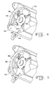
- Fig. 4 is a perspective view of an embodiment of a fan section of the present invention installed within a straw chopper;
- Fig. 5 is a perspective view of another embodiment of a fan section of the present invention installed within a straw chopper;
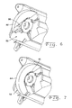
- Fig. 6 is a perspective view of yet another embodiment of a fan section of the present invention installed within a straw chopper; and
- Fig. 7 is a perspective view of a further embodiment of a fan section of the present invention installed within a straw chopper.
- Fig. 1 shows an agricultural harvesting machine in the form of a
combine 10 including a supporting structure 12 having groundengaging wheels 14 extending from supporting structure 12. Althoughcombine 10 is illustrated as havingwheels 14, it could also have ground engaging tracks, either full tracks or half tracks. Aharvesting platform 16 is used for harvesting a crop and directing it to afeederhouse 18. The harvested crop is directed by feederhouse 18 to an infeedbeater 20, which directs the crop upwardly through aninlet transition section 22 to an axialcrop processing unit 24. -
Crop processing unit 24 threshes and separates the harvested crop material.Crop processing unit 24 includes arotor 26 located inside arotor housing 28.Rotor 26 includes a cylindrical rotor drum having a number of threshing elements for threshing the harvested crop material. Grain and chaff fall through grates on the bottom ofcrop processing unit 24 to cleaning system 9 which removes the chaff and directs the clean grain to a clean grain elevator (not shown). The clean grain elevator transports the clean grain tograin tank 30. The clean grain intank 30 can be unloaded into a gravity wagon or truck by anunloading auger 32. - Crop material other than grain is expelled from axial
crop processing unit 24 to dischargebeater 34.Discharge beater 34 in turn propels the harvested crop material other than grain tostraw chopper 36, which chops and flails the non-grain material back to the field. The operation ofcombine 10 is controlled from an operator'scab 38. - Although the invention is illustrated as being used on a rotary combine, the present invention can be used on other combine types including conventional straw walker combines and hybrid combines having transverse threshing cylinders and rotary separators.
- Referring now to Figs. 1 and 2, conjunctively,
straw chopper 36 includes ahousing 40,rotor 42, and a bank ofstationary knives 44.Housing 40 is provided with aninlet 46 for receiving previously processed crop material other than grain and anoutlet 48 for discharging the chopped, non-grain crop material back to the field.Housing 40 also carries the bank ofstationary knives 44. In Fig. 1,rotor 42 would rotate in a counter-clockwise direction. -
Rotor 42, shown in more detail in Figs. 2 and 3, may be divided into three sections; namely, acenter chopping section 50 and a pair offans 52 at each longitudinal end ofchopping section 50. Incenter chopping section 50,rotor 42 is provided with a plurality ofblade mounts 54 for pendulously mountingstraw chopper blades 56.Blades 56 include a flat section with a sharp forward cutting edge, the flat section extending in the direction of rotation. Theblades 56 cooperate withstationary knives 44 to chop the non-grain crop material.Blades 56 also include apaddle 58 transversely extending from the flat section.Paddles 58 are positioned at the radially inward end ofblades 56 to act as fan blades assisting in discharge of the non-grain crop material to the field, without interfering withstationary knives 44. - Referring to Figs. 2-4, each
fan 52 generally includes ahub 60,ring 62,fan blades 64, and scrollhousing 66.Hub 60 is rotatable in a direction of rotation as indicated byarrow 68.Ring 62 is mounted tohub 60 and interconnects the plurality offan blades 64 withhub 60 at a plurality of angularly spaced locations abouthub 60 andring 62. In the embodiment shown,fan 52 includes fourfan blades 64, but a different number of fan blades can also be used. - Each
fan blade 64 has a mounting orproximal end 70 and a radially outboard ordistal end 72. Eachfan blade 64 has a generally U-shaped portion as viewed and extending fromdistal end 72. The U-shaped portion is defined by arear wall 74 and a pair ofside walls 76 extending fromrear wall 74 in direction ofrotation 68. Eachfan blade 64 also has a generally L-shape as viewed perpendicular to one ofside walls 76. In other words, eachfan blade 64 has a "scoop shape" open in the direction of rotation which assists in directing an enhanced flow of air fromstraw chopper 36 for better distributing the non-grain material to the field. - Each
fan blade 46 is also shown as including a pair ofears 78 extending fromrespective side walls 76 nearproximal end 70. Eachear 78 extends generally in the direction ofrotation 68, although also at an acute angle.Ears 78 are mounted on opposite sides ofring 62, and allow free movement offan blades 64 at the mounting locations withring 62, such as at rest or during a plugging situation. Of course, centrifugal force during operation causesfan blades 64 to move to the radially outward position as shown in Fig. 3. - Referring to Figs. 4-7, each
fan 52 is also shown as including a scroll housing which may be of different configurations, although such a scroll housing may not be required for certain applications. In the embodiment shown in Fig. 4, scrollhousing 66 is in the form of a tapered front scroll housing with shallow sides. Scrollhousing 66 assists in directing an enhanced flow of air fromstraw chopper 36. Other embodiments of scroll housings are shown in Figs. 5-7. Fig. 5 illustrates afull scroll housing 80 with shallow sides; Fig. 6 illustrates a taperedfront scroll housing 82 with deep sides; and Fig. 7 illustrates afull scroll housing 84 with deep sides. The differences are readily apparent and thus not described further. - To also assist in providing enhanced air flow,
housing 40 ofstraw chopper 36 may include a plurality of optional air intake holes 86 at opposite longitudinal ends of rotor 42 (Figs. 4-7). Air is drawn axially intofans 52 through air intake holes 86 and discharged in a radial direction usingfan blades 64.
Claims (11)
- A straw chopper (36) for an agricultural harvesting machine, comprising:a housing (40);a rotor (42) carried in said housing (40), said rotor (42) including a center chopping section (50) comprising pendulously mounted straw chopper blades (56) cooperating with stationary knifes (44) mounted to said housing (40) and a pair of fans (52) respectively positioned at longitudinally outboard ends of said center chopping section (50), each said fan (52) including:a hub (60) rotatable in a direction of rotation; anda plurality of fan blades (64) connected with said hub (60) at a plurality of angularly spaced locations about said hub (60), characterized in that a scroll housing (66, 80, 82, 84) is attached to said housing (40) and positioned radially outboard from said plurality of fan blades (64).
- The straw chopper (36) of claim 1, wherein said fan blades (64) have a generally U-shaped portion with a rear wall (74) and a pair of side walls (76) extending from said rear wall (76) in said direction of rotation.
- The straw chopper (36) of claim 1 or 2, further including a ring (62) mounted to said hub (60) which interconnects said plurality of fan blades (64) with said hub (60).
- The straw chopper (36) of one of claims 1 to 3, wherein each said fan blade (64) has a distal end (72) opposite from said hub (60), said U-shaped portion extending from said distal end (72) toward said hub (60).
- The straw chopper (36) of one of claims 1 to 4, wherein each said fan blade (64) has a proximal end (70) closest to said hub (60), each said side wall (76) including an ear (78) adjacent said proximal end (70).
- The straw chopper (36) of claim 5, wherein each said ear (78) extends generally in said direction of rotation.
- The straw chopper (36) of claim 5 or 6, wherein said fan blade (64) has a pair of ears (78) mounted on opposite sides of said ring (62).
- The straw chopper (36) of one of claims 1 to 7, wherein each said fan blade (64) has a distal end (72) opposite from said hub (60), each said fan blade (64) having a generally L-shape as viewed perpendicular to one of said side walls (76).
- The straw chopper (36) of one of claims 1 to 8, wherein said scroll housing (66, 82, 84, 86) includes one of:a tapered front scroll housing (66) with shallow sides;a full scroll housing (80) with shallow sides;a tapered front scroll housing (82) with deep sides; anda full scroll housing (84) with deep sides.
- The straw chopper (36) of one of claims 1 to 9, wherein said housing (40) includes at least one air intake hole (86) at opposite ends of said rotor (42).
- An agricultural harvesting machine, comprising:a crop processing unit; anda straw chopper according to one of the preceding claims receiving primarily non-grain crop material from said crop processing unit.
Applications Claiming Priority (1)
| Application Number | Priority Date | Filing Date | Title |
|---|---|---|---|
| US11/193,937 US7404761B2 (en) | 2005-07-29 | 2005-07-29 | Straw chopper with fan having enhanced air flow in an agricultural combine |
Publications (3)
| Publication Number | Publication Date |
|---|---|
| EP1754408A2 true EP1754408A2 (en) | 2007-02-21 |
| EP1754408A3 EP1754408A3 (en) | 2012-01-18 |
| EP1754408B1 EP1754408B1 (en) | 2013-03-27 |
Family
ID=37532976
Family Applications (1)
| Application Number | Title | Priority Date | Filing Date |
|---|---|---|---|
| EP06117569A Not-in-force EP1754408B1 (en) | 2005-07-29 | 2006-07-20 | Straw chopper with a fan |
Country Status (6)
| Country | Link |
|---|---|
| US (1) | US7404761B2 (en) |
| EP (1) | EP1754408B1 (en) |
| AR (1) | AR056679A1 (en) |
| AU (1) | AU2006203288B2 (en) |
| BR (1) | BRPI0602893B1 (en) |
| CA (1) | CA2554178C (en) |
Cited By (3)
| Publication number | Priority date | Publication date | Assignee | Title |
|---|---|---|---|---|
| EP3158848A1 (en) | 2015-10-21 | 2017-04-26 | Deere & Company | Combine harvester with cleaning ventilation through a suction fan driven by the straw shredder shaft |
| CN107517645A (en) * | 2017-08-18 | 2017-12-29 | 上官倩 | Wheat wheat stubble, device for recovering straw |
| WO2018162974A1 (en) * | 2017-03-06 | 2018-09-13 | Agco Do Brazil Comercio E Industria Ltda | Apparatus for chopping and discharging crop residue from a combine harvester |
Families Citing this family (8)
| Publication number | Priority date | Publication date | Assignee | Title |
|---|---|---|---|---|
| BRPI0818304A2 (en) * | 2007-11-01 | 2014-09-23 | Univ Iowa State Res Found Inc | AIR MOVEMENT UNIT FOR IMPROVING PERFORMANCE OF TRANSPORT, SEPARATION OR BIOMASS CLEANING AND BURNING MACHINE. |
| GB201113858D0 (en) * | 2010-12-13 | 2011-09-28 | Agco Corp | Twin straw chopper |
| US8984851B2 (en) * | 2011-11-01 | 2015-03-24 | Agco Corporation | Chopper attachment to improve conditioning of bio-mass type crops |
| RU2536454C1 (en) * | 2013-08-15 | 2014-12-27 | Федеральное государственное бюджетное образовательное учреждение высшего профессионального образования "Кубанский государственный аграрный университет" | Unit for straw crushing and spreading |
| CA2901446A1 (en) * | 2014-10-24 | 2016-04-24 | Dean Mayerle | Cutting blade |
| US10271477B2 (en) | 2017-01-09 | 2019-04-30 | Cnh Industrial America Llc | Crop residue spreader for a combine harvester |
| DE102020108083A1 (en) * | 2020-03-24 | 2021-09-30 | Claas Selbstfahrende Erntemaschinen Gmbh | Method for operating a self-propelled combine harvester and self-propelled combine harvester |
| CN113906909A (en) * | 2021-11-04 | 2022-01-11 | 李景秋 | Straw collector with suction type double fans |
Citations (5)
| Publication number | Priority date | Publication date | Assignee | Title |
|---|---|---|---|---|
| US6113491A (en) | 1995-09-06 | 2000-09-05 | Rekordverden Sweden Ab | Rotary chopper for a harvester combine |
| WO2000078126A1 (en) | 1999-06-16 | 2000-12-28 | Franz Schrattenecker | Straw cutter for a combine harvester |
| EP1223683A2 (en) | 1994-07-06 | 2002-07-17 | NTT Mobile Communications Network, Inc. | Mobile communication system using base station frequency correction scheme |
| US6840854B2 (en) | 2002-08-30 | 2005-01-11 | Leo Redekop | Apparatus for chopping and discharging straw from a combine harvester |
| WO2005022980A2 (en) | 2003-09-09 | 2005-03-17 | Redekop Chaff Systems Ltd. | Air boost to improve straw chopper spreading in a combine harvester |
Family Cites Families (18)
| Publication number | Priority date | Publication date | Assignee | Title |
|---|---|---|---|---|
| US9114A (en) * | 1852-07-13 | Joseph g | ||
| US3025067A (en) * | 1960-09-07 | 1962-03-13 | Avco Corp | Flail beater unit for a spreader and scattering device |
| US3103241A (en) * | 1962-02-23 | 1963-09-10 | Weigel Alois | Straw chopper and blower |
| FR1427499A (en) | 1964-12-10 | 1966-02-04 | O M A Officine Macchine Agrico | Agricultural machine for collecting, chopping and scattering rice straw and the like |
| GB1077271A (en) * | 1965-01-15 | 1967-07-26 | Anton Bertil Groenberg | An improved rotor for apparatuses intended for the disintegration of straw and simiar material |
| CA1043663A (en) * | 1975-12-08 | 1978-12-05 | E. Charles Moeller | Comminuting apparatus |
| US4696432A (en) * | 1986-04-25 | 1987-09-29 | Deere & Company | Forage harvester blower |
| DE3925701C2 (en) | 1989-08-03 | 1997-04-03 | Claas Ohg | Straw chopper, especially for attachment to a self-propelled combine |
| US5232405A (en) * | 1992-01-07 | 1993-08-03 | Redekop Leo L | Apparatus for chopping and discharging straw from a combine harvester |
| US5482508A (en) * | 1995-03-31 | 1996-01-09 | Redekop; Leo L. | Apparatus for chopping and discharging straw from a combine harvester |
| DE19749338C2 (en) * | 1997-11-07 | 2000-02-17 | Franz Schrattenecker | Chopper for shredding straw, preferably straw |
| DE19823489A1 (en) * | 1998-05-26 | 1999-12-02 | Franz Schrattenecker | Chopper for shredding straw |
| US6478674B2 (en) * | 1999-11-24 | 2002-11-12 | Leo Redekop | Apparatus including twisted blades passing between stationary blades for chopping and discharging straw from a combine harvester |
| DE10107776A1 (en) * | 2001-02-16 | 2003-05-08 | Claas Selbstfahr Erntemasch | Conveying elements and shredding device for agricultural machinery |
| US6692351B2 (en) * | 2002-07-17 | 2004-02-17 | Case Corporation | Crop residue chopper with reconfigurable fixed offset blades |
| US7104883B2 (en) * | 2003-06-23 | 2006-09-12 | Deere & Company | Straw chopper blade |
| DE102004048115B4 (en) * | 2004-10-02 | 2012-09-13 | Deere & Company | Rotor for a straw chopper |
| DE102004049965A1 (en) | 2004-10-14 | 2006-04-27 | Deere & Company, Moline | Rotor for a straw chopper |
-
2005
- 2005-07-29 US US11/193,937 patent/US7404761B2/en not_active Expired - Lifetime
-
2006
- 2006-07-20 AR ARP060103120A patent/AR056679A1/en active IP Right Grant
- 2006-07-20 EP EP06117569A patent/EP1754408B1/en not_active Not-in-force
- 2006-07-24 BR BRPI0602893-4A patent/BRPI0602893B1/en active IP Right Grant
- 2006-07-27 CA CA2554178A patent/CA2554178C/en not_active Expired - Fee Related
- 2006-07-28 AU AU2006203288A patent/AU2006203288B2/en not_active Ceased
Patent Citations (5)
| Publication number | Priority date | Publication date | Assignee | Title |
|---|---|---|---|---|
| EP1223683A2 (en) | 1994-07-06 | 2002-07-17 | NTT Mobile Communications Network, Inc. | Mobile communication system using base station frequency correction scheme |
| US6113491A (en) | 1995-09-06 | 2000-09-05 | Rekordverden Sweden Ab | Rotary chopper for a harvester combine |
| WO2000078126A1 (en) | 1999-06-16 | 2000-12-28 | Franz Schrattenecker | Straw cutter for a combine harvester |
| US6840854B2 (en) | 2002-08-30 | 2005-01-11 | Leo Redekop | Apparatus for chopping and discharging straw from a combine harvester |
| WO2005022980A2 (en) | 2003-09-09 | 2005-03-17 | Redekop Chaff Systems Ltd. | Air boost to improve straw chopper spreading in a combine harvester |
Cited By (7)
| Publication number | Priority date | Publication date | Assignee | Title |
|---|---|---|---|---|
| EP3158848A1 (en) | 2015-10-21 | 2017-04-26 | Deere & Company | Combine harvester with cleaning ventilation through a suction fan driven by the straw shredder shaft |
| DE102015220561A1 (en) | 2015-10-21 | 2017-04-27 | Deere & Company | Combine with cleaning vent through a suction fan driven by the straw chopper shaft |
| US9872439B2 (en) | 2015-10-21 | 2018-01-23 | Deere & Company | Combine having cleaning venting by a suction blower driven by the straw chopper shaft |
| WO2018162974A1 (en) * | 2017-03-06 | 2018-09-13 | Agco Do Brazil Comercio E Industria Ltda | Apparatus for chopping and discharging crop residue from a combine harvester |
| US11716933B2 (en) | 2017-03-06 | 2023-08-08 | Agco Do Brasil Soluções Agrícolas Ltda. | Apparatus for chopping and discharging crop residue from a combine harvester |
| CN107517645A (en) * | 2017-08-18 | 2017-12-29 | 上官倩 | Wheat wheat stubble, device for recovering straw |
| CN107517645B (en) * | 2017-08-18 | 2019-06-14 | 山西金禾丰农业开发有限公司 | Wheat wheat stubble, device for recovering straw |
Also Published As
| Publication number | Publication date |
|---|---|
| BRPI0602893A (en) | 2007-03-13 |
| AU2006203288A1 (en) | 2007-02-15 |
| CA2554178C (en) | 2011-04-19 |
| CA2554178A1 (en) | 2007-01-29 |
| AU2006203288B2 (en) | 2012-04-19 |
| EP1754408B1 (en) | 2013-03-27 |
| AR056679A1 (en) | 2007-10-17 |
| US7404761B2 (en) | 2008-07-29 |
| EP1754408A3 (en) | 2012-01-18 |
| US20070026911A1 (en) | 2007-02-01 |
| BRPI0602893B1 (en) | 2015-03-31 |
Similar Documents
| Publication | Publication Date | Title |
|---|---|---|
| US7104883B2 (en) | Straw chopper blade | |
| US12114609B2 (en) | Integrated weed seed mill and chopper for combine harvester | |
| US9345198B2 (en) | Residue chopping and distribution arrangement for a combine harvester | |
| US8146336B2 (en) | Harvested crop residue chopping and distribution arrangement for a combine with an impeller blower | |
| EP3266297B1 (en) | Crop residue spreader | |
| US8864561B2 (en) | Harvested crop residue chopper and distribution arrangement for a combine with an impeller blower whose shape conforms to the contour of the straw chopper | |
| EP3414990B1 (en) | Cleaning shoe venting through chopper rotor assembly | |
| EP1754408B1 (en) | Straw chopper with a fan | |
| US8128466B2 (en) | Harvested material residue chopping and distributing arrangement for a combine | |
| US6979261B1 (en) | Dust reducing airflow diverter for combine | |
| CA1156531A (en) | Combined chopper and impeller for an axial flow combine | |
| US11716933B2 (en) | Apparatus for chopping and discharging crop residue from a combine harvester | |
| EP1872646B1 (en) | Rotating inlet for cross flow fan. | |
| US11812701B2 (en) | Tangential feeding to a threshing rotor | |
| US20020169011A1 (en) | Flail straw chopper blade | |
| CA2119708C (en) | Notched helical vanes in the feeding section of an axial agricultural combine | |
| US20120264493A1 (en) | Twin Straw Chopper | |
| EP4132261B1 (en) | Threshing system and chopper for combine harvester | |
| US20250331464A1 (en) | Aspiration system for agricultural vehicle | |
| GB2342269A (en) | Improvements in Combine Harvesters | |
| JP2005218392A (en) | Normal combine |
Legal Events
| Date | Code | Title | Description |
|---|---|---|---|
| PUAI | Public reference made under article 153(3) epc to a published international application that has entered the european phase |
Free format text: ORIGINAL CODE: 0009012 |
|
| AK | Designated contracting states |
Kind code of ref document: A2 Designated state(s): AT BE BG CH CY CZ DE DK EE ES FI FR GB GR HU IE IS IT LI LT LU LV MC NL PL PT RO SE SI SK TR |
|
| AX | Request for extension of the european patent |
Extension state: AL BA HR MK YU |
|
| PUAL | Search report despatched |
Free format text: ORIGINAL CODE: 0009013 |
|
| AK | Designated contracting states |
Kind code of ref document: A3 Designated state(s): AT BE BG CH CY CZ DE DK EE ES FI FR GB GR HU IE IS IT LI LT LU LV MC NL PL PT RO SE SI SK TR |
|
| AX | Request for extension of the european patent |
Extension state: AL BA HR MK RS |
|
| RIC1 | Information provided on ipc code assigned before grant |
Ipc: A01F 12/40 20060101ALI20111214BHEP Ipc: A01D 43/10 20060101AFI20111214BHEP |
|
| 17P | Request for examination filed |
Effective date: 20120718 |
|
| AKX | Designation fees paid |
Designated state(s): BE DE FR GB IT |
|
| GRAP | Despatch of communication of intention to grant a patent |
Free format text: ORIGINAL CODE: EPIDOSNIGR1 |
|
| RIC1 | Information provided on ipc code assigned before grant |
Ipc: A01D 43/10 20060101AFI20121019BHEP Ipc: A01F 12/40 20060101ALI20121019BHEP |
|
| RIN1 | Information on inventor provided before grant (corrected) |
Inventor name: PEARSON, MARK L. Inventor name: DOW, CHAD A. |
|
| GRAS | Grant fee paid |
Free format text: ORIGINAL CODE: EPIDOSNIGR3 |
|
| GRAA | (expected) grant |
Free format text: ORIGINAL CODE: 0009210 |
|
| AK | Designated contracting states |
Kind code of ref document: B1 Designated state(s): BE DE FR GB IT |
|
| REG | Reference to a national code |
Ref country code: GB Ref legal event code: FG4D |
|
| REG | Reference to a national code |
Ref country code: DE Ref legal event code: R096 Ref document number: 602006035265 Country of ref document: DE Effective date: 20130529 |
|
| PLBE | No opposition filed within time limit |
Free format text: ORIGINAL CODE: 0009261 |
|
| STAA | Information on the status of an ep patent application or granted ep patent |
Free format text: STATUS: NO OPPOSITION FILED WITHIN TIME LIMIT |
|
| 26N | No opposition filed |
Effective date: 20140103 |
|
| GBPC | Gb: european patent ceased through non-payment of renewal fee |
Effective date: 20130720 |
|
| REG | Reference to a national code |
Ref country code: DE Ref legal event code: R097 Ref document number: 602006035265 Country of ref document: DE Effective date: 20140103 |
|
| REG | Reference to a national code |
Ref country code: FR Ref legal event code: ST Effective date: 20140331 |
|
| PG25 | Lapsed in a contracting state [announced via postgrant information from national office to epo] |
Ref country code: GB Free format text: LAPSE BECAUSE OF NON-PAYMENT OF DUE FEES Effective date: 20130720 |
|
| PG25 | Lapsed in a contracting state [announced via postgrant information from national office to epo] |
Ref country code: FR Free format text: LAPSE BECAUSE OF NON-PAYMENT OF DUE FEES Effective date: 20130731 |
|
| PGFP | Annual fee paid to national office [announced via postgrant information from national office to epo] |
Ref country code: BE Payment date: 20190729 Year of fee payment: 14 |
|
| REG | Reference to a national code |
Ref country code: BE Ref legal event code: MM Effective date: 20200731 |
|
| PG25 | Lapsed in a contracting state [announced via postgrant information from national office to epo] |
Ref country code: BE Free format text: LAPSE BECAUSE OF NON-PAYMENT OF DUE FEES Effective date: 20200731 |
|
| PGFP | Annual fee paid to national office [announced via postgrant information from national office to epo] |
Ref country code: IT Payment date: 20220721 Year of fee payment: 17 |
|
| PG25 | Lapsed in a contracting state [announced via postgrant information from national office to epo] |
Ref country code: IT Free format text: LAPSE BECAUSE OF NON-PAYMENT OF DUE FEES Effective date: 20230720 |
|
| PGFP | Annual fee paid to national office [announced via postgrant information from national office to epo] |
Ref country code: DE Payment date: 20240620 Year of fee payment: 19 |
|
| REG | Reference to a national code |
Ref country code: DE Ref legal event code: R119 Ref document number: 602006035265 Country of ref document: DE |
|
| PG25 | Lapsed in a contracting state [announced via postgrant information from national office to epo] |
Ref country code: DE Free format text: LAPSE BECAUSE OF NON-PAYMENT OF DUE FEES Effective date: 20260203 |