EP1753639B1 - Device for securing a wheel of an upright motorcycle to a trailer - Google Patents
Device for securing a wheel of an upright motorcycle to a trailer Download PDFInfo
- Publication number
- EP1753639B1 EP1753639B1 EP05746996A EP05746996A EP1753639B1 EP 1753639 B1 EP1753639 B1 EP 1753639B1 EP 05746996 A EP05746996 A EP 05746996A EP 05746996 A EP05746996 A EP 05746996A EP 1753639 B1 EP1753639 B1 EP 1753639B1
- Authority
- EP
- European Patent Office
- Prior art keywords
- frame member
- portions
- wheel
- tyre
- motorcycle
- Prior art date
- Legal status (The legal status is an assumption and is not a legal conclusion. Google has not performed a legal analysis and makes no representation as to the accuracy of the status listed.)
- Expired - Lifetime
Links
Images


Classifications
-
- B—PERFORMING OPERATIONS; TRANSPORTING
- B60—VEHICLES IN GENERAL
- B60P—VEHICLES ADAPTED FOR LOAD TRANSPORTATION OR TO TRANSPORT, TO CARRY, OR TO COMPRISE SPECIAL LOADS OR OBJECTS
- B60P3/00—Vehicles adapted to transport, to carry or to comprise special loads or objects
- B60P3/06—Vehicles adapted to transport, to carry or to comprise special loads or objects for carrying vehicles
- B60P3/07—Vehicles adapted to transport, to carry or to comprise special loads or objects for carrying vehicles for carrying road vehicles
- B60P3/073—Vehicle retainers
- B60P3/075—Vehicle retainers for wheels, hubs, or axle shafts
-
- B—PERFORMING OPERATIONS; TRANSPORTING
- B62—LAND VEHICLES FOR TRAVELLING OTHERWISE THAN ON RAILS
- B62H—CYCLE STANDS; SUPPORTS OR HOLDERS FOR PARKING OR STORING CYCLES; APPLIANCES PREVENTING OR INDICATING UNAUTHORIZED USE OR THEFT OF CYCLES; LOCKS INTEGRAL WITH CYCLES; DEVICES FOR LEARNING TO RIDE CYCLES
- B62H3/00—Separate supports or holders for parking or storing cycles
- B62H3/04—Separate supports or holders for parking or storing cycles involving forked supports of brackets for holding a wheel
Definitions
- This invention provides a device according to the preamble of claim 1, for securing a motorcycle in an upright position, for example, during transportation, storage or display.
- a means of anchoring a motorcycle to a base is by using a pair of tie-downs, each in the form of a strap and having a hook provided at each end.
- Each of the straps may be made of a nylon material of suitable strength and is provided with adjustment means in the form of a buckle or ratchet.
- the motorcycle In use, the motorcycle is manoeuvred to locate the tyre of its front wheel on the in a cradle or stand. In some instances, the motorcycle is simply placed onto the base or trailer without use of the stand or cradle. One end of each tie down is hooked at either side of the handlebar or fork. The other end of each tie down is then hooked to an anchor point in the ground or other base for the cradle or stand.
- the straps are tensioned by adjusting the buckle or ratchet to pull down on the handlebar or fork of the motorcycle, such as to compress the fork about halfway and secure the motorcycle in position.
- a disadvantage with using such tie downs is that considerable stress is placed on the motorcycle's suspension, resulting in wheel or fork alignment problems, uneven tyre wear or early fork seal failure.
- Another arrangement consists of a metal stand or cradle for receiving the front wheel of a motorcycle.
- the stand or cradle has adjustable side plates between which the tyre of that wheel can be clamped to secure the vehicle.
- Such stands need to be fixed or bolted to a floor if used in the transportation of a motorcycle, and require the use of additional safety straps to maintain stability of the motorcycle in transit.
- the present invention seeks to provide an alternative form of device.
- a device for securing at least one wheel of a motorcycle to a surface said device, when securing the wheel, being arranged in such a way that a straight line connecting the attachment members is substantially parallel to the wheel axis, thereby maintaining said motorcycle in a substantially upright position relative to said surface when said at least one wheel is secured to said surface, said device including a frame member locatable over an upper portion of a tyre of said at least one wheel of said motorcycle, and a respective tie down attachable to each of opposite sides of said frame member, wherein each tie down includes an attachment member at its end remote from said frame member, whereby when said frame member is located over said tyre, said at least one wheel is able to be secured to said surface by engaging each attachment member with an anchor point situated below said frame member.
- the frame member may have a first portion and a second portion which are disposed relative to each other such that the frame member is substantially symmetrical with respect to the positioning of said first and second portions on said type when said device is located over or secured to said at least one wheel.
- Each of those portions may be of U-shape and have an arcuate web which conforms to the curvature of the tyre.
- each U-shaped portion has legs which diverge from its web, with the webs of the first and second portions spaced apart to engage the tyre at circumferentially spaced locations.
- a connecting member or bracket may be provided between these first and second portions.
- the frame member may have at least one elongate load distributing member which is arcuately shaped to conform to the curvature of the tyre.
- a single load distributing member may extend between the first and second portions of the frame member.
- each of the first and second portions of the frame member may be provided with a respective load distributing member.
- the or each load distributing member may be accommodated within the U-shaped portion of each of the first and second portions and preferably is itself U-shaped in cross-section.
- the tie downs are in the form of adjustable straps.
- the attachment member may be in the form of a hook or other anchoring element.
- the anchor point is located on a base structure or adjacent wall.
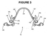
- FIGs 1 and 3 depict a device 10 according to the invention for securing a vehicle.
- the securing device 10 has a frame member 20 and tie-downs 50.
- the tie downs 50 may be attached to the frame member prior to use or may be attached once the frame member is located over the tyre of a wheel.
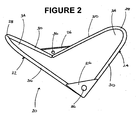
- Views of the frame member 20 alone are provided by Figures 2 and 4 .
- the frame member 20 is made of a material of suitable strength, such as a metal or a plastics material such as polyvinylchloride.
- the frame member 20 has a first portion 22 and a second portion 24 each having a substantially U-shaped configuration.
- Each of portions 22 and 24 has a pair of legs 30 joined by an arcuate web 28 from which the legs 30 diverge.
- each bracket 26 is of triangular form, and a leg 30 of each portion 22 and 24 extends along a respective side of the bracket 26.
- each of portions 22 and 24 is in a respective one of mutually inclined planes.
- frame member 20 is of inverted U-shape as viewed from either end, as shown in Figure 3 , and of V-shape as viewed from either side parallel to the plane of Figure 3 , as is evident from Figures 1 and 2 .
- Each tie down 50 includes an adjustment device 54 at one end, an attachment member 58 at its other end, and a flexible, substantially inextensible strap 52 which interconnects device 54 and member 58.
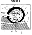
- the member 58 is secured to one end of strap 52, while strap 52 is adjustable engaged by device 54.
- device 54 is adjustable or operable to adjust strap 52 longitudinally for varying the spacing between device 54 and member 58.
- each device 54 is secured to a respective bracket 26 of frame member 20. In each case, this is by means of a bolt 51 which projects from device 54 and engages in an aperture 36 of the respective bracket 26.
- each device 54 is in the form of a ratchet assembly which has a housing 53 from which bolt 51 projects, and a ratchet handle 56 pivotably movable on housing 53 by pin 55. The handle is pivotable to draw the strap 52 longitudinally for reducing the spacing between member 58 and housing 53, while a release mechanism (not visible) enables strap 52 to be pulled in the other direction.
- the member 58 in the arrangement shown, is in the form of a hook.
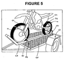
- Figures 5 and 6 depict the securing device 10 in use to secure a motorcycle 60 on a trailer 62 during transit.
- the front wheel 64 of the motorcycle 60 is located in a wheel guard or brace 68.
- a first securing device 10 is then located to position its frame member 20 over the upper portion of the back wheel 66 of the motorcycle 60 so that the portions 22 and 24 are substantially symmetrically disposed with respect to the wheel 66.
- the upper portion of the tyre 61 is received in the space 34 within each arcuate web 28.
- the hook 58 of each tie down 50 is then hooked to a respective anchoring point in the base 63 of the trailer 62, and the straps 52 are tightened by working the ratchet handle 56 to tension the straps 52 for maintaining the motorcycle 60 securely in place.
- the tyres shown in Figures 5 and 6 are slicks and have little, if any, tread patterning. Where the tyres are treaded with a cross-groove arrangement, the webs 28 are able to be located within the grooves of the tread pattern for more secure fit.
- the base 63 of the trailer 62 shown is in the form of a grating, and each hook 58 is hooked under the grating lattice 65.
- anchoring points for example each in the form of an eye or hook, can be affixed to the base for receiving hooks 58.
- the anchoring points may also be located in side walls of a narrow enclosure (not shown) provided the anchoring point is at a height below the frame member 20 when in position on a wheel.
- a second securing device 10 may be similarly fitted over to the front wheel 64 of the motorcycle 60 as shown in Figure 5 . No other securing means is necessary to secure the motorcycle.
- the securing device 10 may be used to secure other wheeled vehicles to a base.
- the device has a number of applications in transportation, storage or display.
- the brackets 26 may be secured to the portions 22 and 24, such as by welding, particularly when the frame member 20 is of metal.
- the portions 22 and 24 may be formed integrally with the brackets 26. In either case, the portions need not be joined by brackets 26, but rather they may comprise respective portions of a continuous loop.
- the adjustment device can be of different forms.
- it may comprise an adjustment device operable in the manner of the buckle part such as is provided on the fixed loop of a vehicle seat belt.
- the strap is able to be manually pulled through that device when securing a vehicle.
- other forms of attachment member can be used, whether this be another form of hook or an alternative releasable attaching means.
- the frame member may comprise a single U shaped portion for location over the upper portion of a tyre so that the U shaped portion is disposed at approximately the 12 o'clock position.
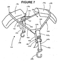
- Figures 7 to 11 depict a second embodiment of the securing device of the invention.
- the structure and working of the embodiment generally will be understood by the description directed to the first embodiment.
- the description of the second embodiment will therefore be limited to principle differences, and to assist with this, the corresponding reference numerals of the second embodiment will be the same as the first embodiment plus 100.
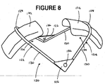
- the first portion 122 and second portion 124 of the frame member 120 are each provided with an elongate load distributing member 172 which is arcuately shaped to conform to the curvature of a tyre.
- Each load distributing member 172 is accommodated within the arcuate web 128 of each of the portions 122 and 124, and is U-shaped in cross-section to correspond to the configuration of the arcuate web 128.
- the load distributing member 172 may be secured to the frame member 120 by welding or other suitable means.
- the load distributing member 172 also assists in maintaining the securing device 110 on the wheel of the vehicle to be secured. Member 172 bears against part of the circumference of the wheel and distributes the load applied for securing the vehicle.
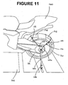
- Figure 11 shows the securing device 110 in use to secure the rear wheel of a motorcycle 160 on a trailer 162 during transit.
- the upper portion of the tyre 161 is received in the space 134 between the arcuate webs 128 and is accommodated within the load distributing members 172.
- the frame member may be provided with a single load distributing member which extends between the first and second portions of the frame member. That is, relative to the embodiment of Figures 7 to 11 , the arrangement may be such that the members 172 are end portions of a single elongate member.
- FIGS 12 to 16 depict a third embodiment of the securing device of the invention.
- the securing device 210 has a frame member 220 and tie-downs 250.
- the frame member 220 has a first portion 222 and a second portion 224 each comprising an elongate strip having a substantially U-shaped configuration.
- Each of portions 222 and 224 has a pair of legs 230 joined by an arcuate web 228 from which the legs 230 diverge.
- the portions 222 and 224 are made of a suitable flexible plastics material, for example of a hard plastics material such as polyvinylchloride or a hard rubber material, such that each pair of legs 230 is able to be flexed apart.
- each of the legs 230 of portions 222 and 224 is provided with an abutment means in the form of a series of fins 240 which, in this instance, are of a substantially triangular configuration.
- the fins 240 may be made of a hard plastics or hard rubber material and they may be formed integrally with the portions 222 and 224.
- a series of fins 240 on one leg 230 is positioned opposite to a series of fins 240 on the other leg 230.
- a series of three fins 240 is provided on each leg 230 such that the faces of the fins 240 on each leg 230 are located in parallel arrangement.
- a slot 242 is provided in the end of each leg 230 adjacent each series of fins 240.
- the portions 222 and 224 are connected by way of a pair of straps 243, the ends of which are received in the slots 242.
- the ends of the each strap 243 are secured to the portions 222 and 224 by means of stitching (not shown) or by any suitable fastener.
- a pair of tie-downs 250 is attached to each side of the frame member 220.
- Each tie-down 250 is attached to the centre portion of each strap 243 and is affixed thereto by stitching (not shown) or by any suitable fastener, for example, a clip.
- the strap 243 is made of a fabric or nylon material of suitable strength.
- strap 243 may be replaced by a rigid or semi-rigid frame which is of substantially V-shaped configuration which is the configuration strap 243 adopts when in use.
- Figures 20 and 21 depict the securing device 210 in use to secure the rear wheel 266 of motorcycle 260 on a trailer 262 during transit.
- the legs 230 of each portion 222 and 224 are flexed apart and located to position frame member 220 over the upper portion of the back wheel 266 of the motorcycle 260 so that the portions 222 and 224 are substantially symmetrically disposed with respect to wheel 266, at approximately the 1 o'clock and 11 o'clock positions.
- the upper portion of the tyre 261 is received in the space 234 between the arcuate webs 28.
- the resilience of portions 222 and 224 is such that they are able to firmly grip tyre 261.
- each tie downs 250 is then hooked to a respective anchoring point in the base 263 of the trailer 262, and the straps are tightened by working the ratchet handle 256 to tension the straps 252 for maintaining the motorcycle 260 securely in place.
- strap 243 adopts a V-shaped configuration.
- Each opposing series of fins 240 engage the grooves of the tyre tread to enable the securing device to be fitted securely.
- portions 222 and 224 is provided with spring along web 228 to enable each portion to be prised or levered open against the bias of the spring acting to force it to a closed position.
- each of portions 222 and 224 is in the form of an elongate strip which is substantially C-shaped to fit closely over the width and rim of the tyre.
- the tie downs are attached as described in the third embodiment.
- the C-shaped portions may be hinged so that they form the same shape as the tyre when fitted.
- Figure 17 depicts a fourth embodiment 310 of the securing device of the invention which is substantially the same in structure and working as the third embodiment with the principle difference being the abutment means on the inner surface of legs 330 in the fourth embodiment is in the form of a substantially triangular shaped member 340 instead of a series of fins 240.
- the cross-section of member 340 is substantially the same as the faces of each of the fins 240.
- the member 340 may be formed integrally with portions 222 and 224.
- Figure 18 depicts a fifth embodiment 410 of the securing device of the invention which is substantially the same in structure and working as the third embodiment with the principle differences being the pair of straps 243 in the third embodiment 210 is replaced by a single continuous strap 343.
- the continuous strap 343, along both its edges, is stitched onto the elongate strips forming portions 222 and 224. As such, there is no need for any slots to be located at the ends of strips 344 as in the third embodiment.
- Figure 19 depicts a sixth embodiment 510 of the securing device of the invention which is substantially the same in structure and working as the third embodiment with the principle difference being the absence of an abutment member on the inner surface of legs 530.
- This embodiment is suitable for use on slick or treadless tyres.
Landscapes
- Engineering & Computer Science (AREA)
- Mechanical Engineering (AREA)
- Health & Medical Sciences (AREA)
- Public Health (AREA)
- Transportation (AREA)
- Motorcycle And Bicycle Frame (AREA)
- Tires In General (AREA)
- Automatic Cycles, And Cycles In General (AREA)
- Body Structure For Vehicles (AREA)
- Handcart (AREA)
Abstract
Description
- This invention provides a device according to the preamble of claim 1, for securing a motorcycle in an upright position, for example, during transportation, storage or display.
- A means of anchoring a motorcycle to a base, for example, of a trailer, display stand or truck, is by using a pair of tie-downs, each in the form of a strap and having a hook provided at each end. Each of the straps may be made of a nylon material of suitable strength and is provided with adjustment means in the form of a buckle or ratchet.
- In use, the motorcycle is manoeuvred to locate the tyre of its front wheel on the in a cradle or stand. In some instances, the motorcycle is simply placed onto the base or trailer without use of the stand or cradle. One end of each tie down is hooked at either side of the handlebar or fork. The other end of each tie down is then hooked to an anchor point in the ground or other base for the cradle or stand. The straps are tensioned by adjusting the buckle or ratchet to pull down on the handlebar or fork of the motorcycle, such as to compress the fork about halfway and secure the motorcycle in position. A disadvantage with using such tie downs is that considerable stress is placed on the motorcycle's suspension, resulting in wheel or fork alignment problems, uneven tyre wear or early fork seal failure.
- Another arrangement consists of a metal stand or cradle for receiving the front wheel of a motorcycle. The stand or cradle has adjustable side plates between which the tyre of that wheel can be clamped to secure the vehicle. However, such stands need to be fixed or bolted to a floor if used in the transportation of a motorcycle, and require the use of additional safety straps to maintain stability of the motorcycle in transit.
- A specific arrangement of a conventional securing device is shown, for example, in
US-1,424,957 . - The present invention seeks to provide an alternative form of device.
- According to the present invention there is provided a device for securing at least one wheel of a motorcycle to a surface, said device, when securing the wheel, being arranged in such a way that a straight line connecting the attachment members is substantially parallel to the wheel axis, thereby maintaining said motorcycle in a substantially upright position relative to said surface when said at least one wheel is secured to said surface, said device including a frame member locatable over an upper portion of a tyre of said at least one wheel of said motorcycle, and a respective tie down attachable to each of opposite sides of said frame member, wherein each tie down includes an attachment member at its end remote from said frame member, whereby when said frame member is located over said tyre, said at least one wheel is able to be secured to said surface by engaging each attachment member with an anchor point situated below said frame member.
- The frame member may have a first portion and a second portion which are disposed relative to each other such that the frame member is substantially symmetrical with respect to the positioning of said first and second portions on said type when said device is located over or secured to said at least one wheel. Each of those portions may be of U-shape and have an arcuate web which conforms to the curvature of the tyre. Preferably, each U-shaped portion has legs which diverge from its web, with the webs of the first and second portions spaced apart to engage the tyre at circumferentially spaced locations. A connecting member or bracket may be provided between these first and second portions.
- The frame member may have at least one elongate load distributing member which is arcuately shaped to conform to the curvature of the tyre. A single load distributing member may extend between the first and second portions of the frame member. Alternatively, each of the first and second portions of the frame member may be provided with a respective load distributing member.
- The or each load distributing member may be accommodated within the U-shaped portion of each of the first and second portions and preferably is itself U-shaped in cross-section.
- Preferably, the tie downs are in the form of adjustable straps.
- The attachment member may be in the form of a hook or other anchoring element. Preferably, the anchor point is located on a base structure or adjacent wall.
- The invention can be more fully understood by reference to the following examplary description with reference with the accompanying drawings, in which:
-
FIGURE 1 is a perspective view of a first embodiment of the securing device of the invention; -
FIGURE 2 is a perspective view of a component of the device ofFigure 1 ; -
FIGURE 3 is a front view of the device ofFigure 1 , in an in use orientation; -
FIGURE 4 is a top view of the component ofFigure 2 in the in use orientation; -
FIGURE 5 is a schematic perspective view of a motorcycle secured on a trailer by use of two of the securing devices ofFigures 1 and3 ; -
FIGURE 6 is a schematic side elevational view of the rear wheel of a motorcycle shown inFigure 5 ; -
FIGURE 7 is a perspective view of a second embodiment of the securing device of the invention; -
FIGURE 8 is a perspective view of a component of the device ofFigure 7 ; -
FIGURE 9 is a front view of the device ofFigure 7 , in an in use orientation; -
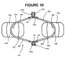
FIGURE 10 is a top view of the component ofFigure 8 in the in use orientation; -
FIGURE 11 is a schematic side elevational view of the rear wheel of a motorcycle secured on a trailer by use of the securing device ofFigures 7 and9 -
FIGURE 12 is a perspective view of a third embodiment of the securing device of the invention; -
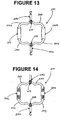
FIGURE 13 is a top view of the device ofFigure 12 in an in use orientation; -
FIGURE 14 is a bottom view of the component ofFigure 12 in the in use orientation; -
FIGURE 15 is a side view of the component ofFigure 12 in the in use orientation; -
FIGURE 16 is a front view of the component ofFigure 12 in the in use orientation; -
FIGURE 17 is a perspective view of a fourth embodiment of the securing device of the invention; -
FIGURE 18 is a perspective view of a fifth embodiment of the securing device of the invention; -
FIGURE 19 is a perspective view of a sixth embodiment of the securing device of the invention; -
FIGURE 20 is a schematic side elevational view of the rear wheel of a motorcycle secured on a trailer by the securing device ofFigure 12 ; and -
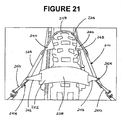
FIGURE 21 is an enlarged schematic rear view of the rear wheel ofFigure 20 . -
Figures 1 and3 depict adevice 10 according to the invention for securing a vehicle. Thesecuring device 10 has aframe member 20 and tie-downs 50. Thetie downs 50 may be attached to the frame member prior to use or may be attached once the frame member is located over the tyre of a wheel. Views of theframe member 20 alone are provided byFigures 2 and4 . Theframe member 20 is made of a material of suitable strength, such as a metal or a plastics material such as polyvinylchloride. - The
frame member 20 has afirst portion 22 and asecond portion 24 each having a substantially U-shaped configuration. Each ofportions legs 30 joined by anarcuate web 28 from which thelegs 30 diverge. - The free end of each
leg 30 of one ofportions respective leg 30 of the other one ofportions respective bracket 26. In the arrangement shown, eachbracket 26 is of triangular form, and aleg 30 of eachportion bracket 26. Thus, each ofportions Figure 1 ,frame member 20 is of inverted U-shape as viewed from either end, as shown inFigure 3 , and of V-shape as viewed from either side parallel to the plane ofFigure 3 , as is evident fromFigures 1 and2 . - Each tie down 50 includes an adjustment device 54 at one end, an
attachment member 58 at its other end, and a flexible, substantiallyinextensible strap 52 which interconnects device 54 andmember 58. Themember 58 is secured to one end ofstrap 52, whilestrap 52 is adjustable engaged by device 54. Also, device 54 is adjustable or operable to adjuststrap 52 longitudinally for varying the spacing between device 54 andmember 58. - Each device 54 is secured to a
respective bracket 26 offrame member 20. In each case, this is by means of abolt 51 which projects from device 54 and engages in anaperture 36 of therespective bracket 26. In the arrangement illustrated, each device 54 is in the form of a ratchet assembly which has ahousing 53 from whichbolt 51 projects, and aratchet handle 56 pivotably movable onhousing 53 bypin 55. The handle is pivotable to draw thestrap 52 longitudinally for reducing the spacing betweenmember 58 andhousing 53, while a release mechanism (not visible) enablesstrap 52 to be pulled in the other direction. Themember 58, in the arrangement shown, is in the form of a hook. -
Figures 5 and6 depict the securingdevice 10 in use to secure amotorcycle 60 on atrailer 62 during transit. Thefront wheel 64 of themotorcycle 60 is located in a wheel guard orbrace 68. Afirst securing device 10 is then located to position itsframe member 20 over the upper portion of theback wheel 66 of themotorcycle 60 so that theportions wheel 66. Thus the upper portion of the tyre 61 is received in thespace 34 within eacharcuate web 28. Thehook 58 of each tie down 50 is then hooked to a respective anchoring point in the base 63 of thetrailer 62, and thestraps 52 are tightened by working theratchet handle 56 to tension thestraps 52 for maintaining themotorcycle 60 securely in place. - The tyres shown in
Figures 5 and6 are slicks and have little, if any, tread patterning. Where the tyres are treaded with a cross-groove arrangement, thewebs 28 are able to be located within the grooves of the tread pattern for more secure fit. - The base 63 of the
trailer 62 shown is in the form of a grating, and eachhook 58 is hooked under the gratinglattice 65. Where the base is a solid surface, anchoring points, for example each in the form of an eye or hook, can be affixed to the base for receiving hooks 58. The anchoring points may also be located in side walls of a narrow enclosure (not shown) provided the anchoring point is at a height below theframe member 20 when in position on a wheel. - For additional security, a
second securing device 10 may be similarly fitted over to thefront wheel 64 of themotorcycle 60 as shown inFigure 5 . No other securing means is necessary to secure the motorcycle. - Although the embodiment of
Figures 1 to 6 has been described with application to motorcycles, the securingdevice 10 may be used to secure other wheeled vehicles to a base. The same applies to the further embodiments ofFigures 7 to 21 . In each case, the device has a number of applications in transportation, storage or display. - The
brackets 26 may be secured to theportions frame member 20 is of metal. Alternatively, particularly where the frame member is of a plastics material, theportions brackets 26. In either case, the portions need not be joined bybrackets 26, but rather they may comprise respective portions of a continuous loop. - In other embodiments, the adjustment device can be of different forms. In one arrangement, it may comprise an adjustment device operable in the manner of the buckle part such as is provided on the fixed loop of a vehicle seat belt. Thus, the strap is able to be manually pulled through that device when securing a vehicle. Also, it will be appreciated, other forms of attachment member can be used, whether this be another form of hook or an alternative releasable attaching means.
- In other embodiments, the frame member may comprise a single U shaped portion for location over the upper portion of a tyre so that the U shaped portion is disposed at approximately the 12 o'clock position.
-
Figures 7 to 11 depict a second embodiment of the securing device of the invention. The structure and working of the embodiment generally will be understood by the description directed to the first embodiment. The description of the second embodiment will therefore be limited to principle differences, and to assist with this, the corresponding reference numerals of the second embodiment will be the same as the first embodiment plus 100. - The
first portion 122 andsecond portion 124 of theframe member 120 are each provided with an elongateload distributing member 172 which is arcuately shaped to conform to the curvature of a tyre. Eachload distributing member 172 is accommodated within thearcuate web 128 of each of theportions arcuate web 128. Theload distributing member 172 may be secured to theframe member 120 by welding or other suitable means. Theload distributing member 172 also assists in maintaining the securingdevice 110 on the wheel of the vehicle to be secured.Member 172 bears against part of the circumference of the wheel and distributes the load applied for securing the vehicle. -
Figure 11 shows the securingdevice 110 in use to secure the rear wheel of amotorcycle 160 on atrailer 162 during transit. The upper portion of thetyre 161 is received in thespace 134 between thearcuate webs 128 and is accommodated within theload distributing members 172. - In another embodiment (not shown), the frame member may be provided with a single load distributing member which extends between the first and second portions of the frame member. That is, relative to the embodiment of
Figures 7 to 11 , the arrangement may be such that themembers 172 are end portions of a single elongate member. -
Figures 12 to 16 depict a third embodiment of the securing device of the invention. The securingdevice 210 has aframe member 220 and tie-downs 250. Theframe member 220 has afirst portion 222 and asecond portion 224 each comprising an elongate strip having a substantially U-shaped configuration. Each ofportions legs 230 joined by anarcuate web 228 from which thelegs 230 diverge. Theportions legs 230 is able to be flexed apart. - The inner surface of each of the
legs 230 ofportions fins 240 which, in this instance, are of a substantially triangular configuration. Thefins 240 may be made of a hard plastics or hard rubber material and they may be formed integrally with theportions portion fins 240 on oneleg 230 is positioned opposite to a series offins 240 on theother leg 230. In the embodiment shown, a series of threefins 240 is provided on eachleg 230 such that the faces of thefins 240 on eachleg 230 are located in parallel arrangement. Aslot 242 is provided in the end of eachleg 230 adjacent each series offins 240. - The
portions straps 243, the ends of which are received in theslots 242. The ends of the eachstrap 243 are secured to theportions downs 250, as described above in relation to the first embodiment, is attached to each side of theframe member 220. Each tie-down 250 is attached to the centre portion of eachstrap 243 and is affixed thereto by stitching (not shown) or by any suitable fastener, for example, a clip. In the embodiment shown, thestrap 243 is made of a fabric or nylon material of suitable strength. - In alternative embodiments,
strap 243 may be replaced by a rigid or semi-rigid frame which is of substantially V-shaped configuration which is theconfiguration strap 243 adopts when in use. -
Figures 20 and21 depict the securingdevice 210 in use to secure therear wheel 266 of motorcycle 260 on a trailer 262 during transit. Thelegs 230 of eachportion frame member 220 over the upper portion of theback wheel 266 of the motorcycle 260 so that theportions wheel 266, at approximately the 1 o'clock and 11 o'clock positions. Thus the upper portion of thetyre 261 is received in the space 234 between thearcuate webs 28. The resilience ofportions tyre 261. - The
hook 258 of eachtie downs 250 is then hooked to a respective anchoring point in the base 263 of the trailer 262, and the straps are tightened by working theratchet handle 256 to tension thestraps 252 for maintaining the motorcycle 260 securely in place. When tensioned,strap 243 adopts a V-shaped configuration. Each opposing series offins 240 engage the grooves of the tyre tread to enable the securing device to be fitted securely. - In an alternative embodiment,
portions web 228 to enable each portion to be prised or levered open against the bias of the spring acting to force it to a closed position. - In an alternative embodiment, each of
portions -
Figure 17 depicts afourth embodiment 310 of the securing device of the invention which is substantially the same in structure and working as the third embodiment with the principle difference being the abutment means on the inner surface oflegs 330 in the fourth embodiment is in the form of a substantially triangular shapedmember 340 instead of a series offins 240. The cross-section ofmember 340 is substantially the same as the faces of each of thefins 240. Themember 340 may be formed integrally withportions -
Figure 18 depicts afifth embodiment 410 of the securing device of the invention which is substantially the same in structure and working as the third embodiment with the principle differences being the pair ofstraps 243 in thethird embodiment 210 is replaced by a singlecontinuous strap 343. Thecontinuous strap 343, along both its edges, is stitched onto the elongatestrips forming portions -
Figure 19 depicts a sixth embodiment 510 of the securing device of the invention which is substantially the same in structure and working as the third embodiment with the principle difference being the absence of an abutment member on the inner surface oflegs 530. This embodiment is suitable for use on slick or treadless tyres. - Various other modifications or variations may be made to the embodiments described without departing from the scope of the invention as defined in the appended claims.
Claims (12)
- A device for securing at least one wheel (64, 66, 266) of a motorcycle (60, 260) to a surface, the device including
a frame member (20, 120, 220) locatable over the upper portion of a tyre (61, 161, 261) of the at least one wheel (64, 66, 266) of the motorcycle (60, 260), and
a respective tie down (50, 150, 250) attachable to each of opposite sides of the frame member (20, 120, 220),
wherein each tie down (50, 150, 250) includes an attachment member (58, 158, 258) at its end remote from the frame member (20, 120, 220),
whereby when the frame member (20, 120, 220) is located over the tyre (61, 161, 261), the at least one wheel (64, 66, 266) is able to be secured to the surface by engaging each attachment member (58, 158, 258) with an anchor point situated below the frame member (20, 120, 220),
characterised in that
the device, when securing the wheel (64, 66, 266), is arranged in such a way that a straight line connecting the attachment members (58, 158, 258) is substantially parallel to the wheel axis thereby maintaining the motorcycle (60, 260) in a substantially upright position relative to the surface when the at least one wheel (64, 66, 266) is secured to the surface. - The device as claimed in claim 1, wherein the frame member (20, 120, 220) has a first portion (22, 122, 222) and a second portion (24, 124, 224) which are disposed relative to each other such that the frame member (20, 120, 220) is substantially symmetrical with respect to the positioning of the first (22, 122, 222) and second (24, 124, 224) portions on the tyre (61, 161, 261) when the device is located over or secured to the at least one wheel (64, 66, 266).
- The device as claimed in claim 2, wherein each of the first (22, 122, 222) and second (24, 124, 224) portions is of U-shape configuration.
- The device as claimed in claim 3, wherein each of the first (22, 122, 222) and second (24, 124, 224) portions includes an arcuate web (28, 128, 228) which conforms to the curvature of the tyre (61, 161, 261), and legs (30, 130, 230, 330, 530) which diverge from the arcuate webs (28, 128, 228), and wherein the arcuate webs (28, 128, 228) of the first (22, 122, 222) and second (24, 124, 224) portions are spaced apart to engage the tyre (61, 161, 261) at circumferentially spaced locations.
- The device as maimed in any one of claims 2 to 4, wherein a connecting member (26, 126) is provided between the first and second portions.
- The device as claimed in claim 5, wherein the connecting member (26, 126) is a bracket.
- The device as claimed in any of the preceding claims, wherein the frame member (20, 120, 220) includes at least one elongate load distributing member (172) which is arcuately shaped to conform to the curvature of the tyre (61, 161, 261).
- The device as claimed in claim 7, when appended to any one of claims 2 to 6, wherein a single load distributing member (172) extends between the first (22, 122, 222) and second (24, 124, 224) portions of the frame member (20, 120, 220).
- The device as claimed in claim 7, when appended to any one of claims 2 to 6, wherein each of the first (22, 122, 222) and second (24, 124, 224) portions of the frame member (20, 120, 220) includes a respective load distributing member (172).
- The device as claimed in claim 7, when appended to claim 3 or claim 4, wherein the at least one load distributing member (172) is accommodated within the U-shaped portion of each of the first (22, 122, 222) and second (24, 124, 224) portions, and is U-shaped in cross-section.
- The device as claimed in any one of the preceding claims, wherein the tie downs (50, 150, 250) are adjustable straps (52, 152, 252).
- The device as claimed in any one of the preceding claims, wherein the attachment members (58, 158, 258) are hooks.
Applications Claiming Priority (3)
| Application Number | Priority Date | Filing Date | Title |
|---|---|---|---|
| AU2004903071A AU2004903071A0 (en) | 2004-06-07 | Device for securing a vehicle | |
| AU2004904545A AU2004904545A0 (en) | 2004-08-12 | Device for securing a vehicle | |
| PCT/AU2005/000812 WO2005120897A1 (en) | 2004-06-07 | 2005-06-07 | Device for securing a wheel of an upright motorcycle to a trailer |
Publications (3)
| Publication Number | Publication Date |
|---|---|
| EP1753639A1 EP1753639A1 (en) | 2007-02-21 |
| EP1753639A4 EP1753639A4 (en) | 2007-06-20 |
| EP1753639B1 true EP1753639B1 (en) | 2009-12-30 |
Family
ID=43354541
Family Applications (1)
| Application Number | Title | Priority Date | Filing Date |
|---|---|---|---|
| EP05746996A Expired - Lifetime EP1753639B1 (en) | 2004-06-07 | 2005-06-07 | Device for securing a wheel of an upright motorcycle to a trailer |
Country Status (11)
| Country | Link |
|---|---|
| US (2) | US7959388B2 (en) |
| EP (1) | EP1753639B1 (en) |
| AT (1) | ATE453538T1 (en) |
| AU (2) | AU2005251824B2 (en) |
| CA (1) | CA2568648C (en) |
| DE (1) | DE602005018636D1 (en) |
| ES (1) | ES2335507T3 (en) |
| NZ (1) | NZ551588A (en) |
| PT (1) | PT1753639E (en) |
| WO (1) | WO2005120897A1 (en) |
| ZA (1) | ZA200700093B (en) |
Families Citing this family (8)
| Publication number | Priority date | Publication date | Assignee | Title |
|---|---|---|---|---|
| NZ551588A (en) * | 2004-06-07 | 2010-04-30 | Kya Racing Pty Ltd | Device for securing a wheel of an upright motorcycle to a trailer |
| AU2007209833A1 (en) * | 2007-08-20 | 2009-03-12 | Quinton Renshaw Hutchinson | Motorcycle transportation restraint system |
| ITBA20120063A1 (en) * | 2012-10-30 | 2014-05-01 | Giuseppe Mazzilli | DEVICE FOR CONNECTING AN ALZAMOTO STAND TO THE REAR FORK OF A MOTORCYCLE. |
| CZ2013485A3 (en) | 2013-06-24 | 2014-08-06 | Vysoká Škola Báňská-Technická Univerzita Ostrava | Adapter for fastening motorcycles onto brake stands |
| US9803715B1 (en) * | 2015-09-11 | 2017-10-31 | Robert J. Simmons | Safety strap apparatus to protect a super single truck rim from damage during a tire blowout |
| US9994142B2 (en) * | 2016-07-06 | 2018-06-12 | Universal City Studios Llc | Personal electric vehicle mount |
| US11400855B2 (en) * | 2020-06-29 | 2022-08-02 | Rivian Ip Holdings, Llc | Integrated tailgate cargo system for automotive vehicle |
| KR102602885B1 (en) * | 2021-12-07 | 2023-11-16 | 넥센타이어 주식회사 | Fastening device for vehicle that reduce flat spots on tire |
Family Cites Families (11)
| Publication number | Priority date | Publication date | Assignee | Title |
|---|---|---|---|---|
| US1131477A (en) * | 1914-09-17 | 1915-03-09 | Cyrus L Casterline | Automobile wheel-holder. |
| US1424957A (en) * | 1920-06-17 | 1922-08-08 | Harry W Van Tilburg | Automobile securing device |
| US1708231A (en) * | 1928-06-22 | 1929-04-09 | Charlie B Moore | Device for shipping automobiles |
| US1770798A (en) * | 1928-10-22 | 1930-07-15 | Nicholson William | Apparatus for securing wheeled vehicles to the decks of ships or other carriers |
| US2023971A (en) | 1931-06-10 | 1935-12-10 | Chicago North Shore & Milwauke | Transportation means |
| US4852779A (en) | 1988-02-16 | 1989-08-01 | Kevin Berg | Collapsible bike rack for automotive vehicle |
| US5586849A (en) | 1994-02-28 | 1996-12-24 | Rushmore Vehicle Restraints, L.L.C. | Wheel restraint device and quick-connect hooks for use therewith |
| US6065914A (en) * | 1996-06-13 | 2000-05-23 | Fotou; Dean H. | Apparatus for securing a vehicle |
| US6139231A (en) * | 1999-09-10 | 2000-10-31 | Rushmore Vehicle Restraints, L.L.C. | Wheel restraint device |
| US6328511B1 (en) | 2000-02-07 | 2001-12-11 | Kinedyne Corporation | Vehicle transport restraint anchor |
| NZ551588A (en) * | 2004-06-07 | 2010-04-30 | Kya Racing Pty Ltd | Device for securing a wheel of an upright motorcycle to a trailer |
-
2005
- 2005-06-07 NZ NZ551588A patent/NZ551588A/en not_active IP Right Cessation
- 2005-06-07 US US11/597,904 patent/US7959388B2/en not_active Expired - Fee Related
- 2005-06-07 DE DE602005018636T patent/DE602005018636D1/en not_active Expired - Lifetime
- 2005-06-07 ES ES05746996T patent/ES2335507T3/en not_active Expired - Lifetime
- 2005-06-07 PT PT05746996T patent/PT1753639E/en unknown
- 2005-06-07 CA CA2568648A patent/CA2568648C/en not_active Expired - Fee Related
- 2005-06-07 AU AU2005251824A patent/AU2005251824B2/en not_active Ceased
- 2005-06-07 AT AT05746996T patent/ATE453538T1/en active
- 2005-06-07 ZA ZA200700093A patent/ZA200700093B/en unknown
- 2005-06-07 WO PCT/AU2005/000812 patent/WO2005120897A1/en not_active Ceased
- 2005-06-07 EP EP05746996A patent/EP1753639B1/en not_active Expired - Lifetime
-
2010
- 2010-05-17 AU AU2010100477A patent/AU2010100477B4/en not_active Expired
- 2010-06-08 US US12/801,422 patent/US20100322735A1/en not_active Abandoned
Also Published As
| Publication number | Publication date |
|---|---|
| ATE453538T1 (en) | 2010-01-15 |
| NZ551588A (en) | 2010-04-30 |
| US20070231098A1 (en) | 2007-10-04 |
| PT1753639E (en) | 2010-03-31 |
| CA2568648C (en) | 2012-04-17 |
| DE602005018636D1 (en) | 2010-02-11 |
| EP1753639A4 (en) | 2007-06-20 |
| ES2335507T3 (en) | 2010-03-29 |
| US7959388B2 (en) | 2011-06-14 |
| EP1753639A1 (en) | 2007-02-21 |
| AU2005251824B2 (en) | 2011-10-27 |
| AU2010100477A4 (en) | 2010-06-10 |
| AU2005251824A1 (en) | 2005-12-22 |
| AU2010100477B4 (en) | 2010-06-24 |
| US20100322735A1 (en) | 2010-12-23 |
| CA2568648A1 (en) | 2005-12-22 |
| ZA200700093B (en) | 2007-09-26 |
| WO2005120897A1 (en) | 2005-12-22 |
Similar Documents
| Publication | Publication Date | Title |
|---|---|---|
| AU2010100477A4 (en) | Device for Securing a Wheel of an Upright Motorcycle to a Trailer | |
| US11752948B2 (en) | Vacuum mounted carrier for a vehicle | |
| US9278704B2 (en) | Wheeled system for coolers | |
| US4562944A (en) | Adjustable connections on cycle rear carrier | |
| KR101860954B1 (en) | Vacuum mounted carrier for a vehicle | |
| US4174795A (en) | Pannier mounting arrangement for cycles | |
| US20080314693A1 (en) | Immobilisation device for a vehicle wheel and method for immobilising a vehicle wheel | |
| US4024738A (en) | Fastener for motorcycle driver's helmet | |
| US9027939B2 (en) | Universal ski conversion device for a stroller or bicycle trailer | |
| US7416373B2 (en) | Motorcycle tie down/lock down system | |
| US4620602A (en) | Track drive converter | |
| US5108237A (en) | Tiedown strap assembly for retaining a vehicle during transportation | |
| US20150291202A1 (en) | Universal ski conversion assembly | |
| US9174699B2 (en) | Bicycle tow device | |
| US6966732B2 (en) | Motorcycle tie down strap device | |
| CN100554035C (en) | Cargo securing system and method | |
| US11325540B2 (en) | Bike carrier | |
| US4266702A (en) | Pannier mounting arrangement for cycles | |
| US20060045645A1 (en) | Tie down apparatus and method of use | |
| CA1060328A (en) | Anti-skid attachment for vehicle tires | |
| US20060144493A1 (en) | Tire chain assembly | |
| US8998050B1 (en) | Bicycle carrying system | |
| US10244827B1 (en) | Safety car seat tightening device and seat wedge for use in installing safety car seats | |
| US20200385073A1 (en) | Collapsible Trailer Device | |
| WO2006025810A2 (en) | Motorcycle tie down strap device |
Legal Events
| Date | Code | Title | Description |
|---|---|---|---|
| PUAI | Public reference made under article 153(3) epc to a published international application that has entered the european phase |
Free format text: ORIGINAL CODE: 0009012 |
|
| 17P | Request for examination filed |
Effective date: 20061122 |
|
| AK | Designated contracting states |
Kind code of ref document: A1 Designated state(s): AT BE BG CH CY CZ DE DK EE ES FI FR GB GR HU IE IS IT LI LT LU MC NL PL PT RO SE SI SK TR |
|
| A4 | Supplementary search report drawn up and despatched |
Effective date: 20070521 |
|
| RIC1 | Information provided on ipc code assigned before grant |
Ipc: B60P 3/075 20060101AFI20060103BHEP Ipc: B62H 3/00 20060101ALI20070515BHEP |
|
| 17Q | First examination report despatched |
Effective date: 20070727 |
|
| DAX | Request for extension of the european patent (deleted) | ||
| GRAP | Despatch of communication of intention to grant a patent |
Free format text: ORIGINAL CODE: EPIDOSNIGR1 |
|
| GRAS | Grant fee paid |
Free format text: ORIGINAL CODE: EPIDOSNIGR3 |
|
| GRAA | (expected) grant |
Free format text: ORIGINAL CODE: 0009210 |
|
| AK | Designated contracting states |
Kind code of ref document: B1 Designated state(s): AT BE BG CH CY CZ DE DK EE ES FI FR GB GR HU IE IS IT LI LT LU MC NL PL PT RO SE SI SK TR |
|
| REG | Reference to a national code |
Ref country code: GB Ref legal event code: FG4D |
|
| REG | Reference to a national code |
Ref country code: CH Ref legal event code: EP |
|
| REG | Reference to a national code |
Ref country code: IE Ref legal event code: FG4D |
|
| REF | Corresponds to: |
Ref document number: 602005018636 Country of ref document: DE Date of ref document: 20100211 Kind code of ref document: P |
|
| REG | Reference to a national code |
Ref country code: ES Ref legal event code: FG2A Ref document number: 2335507 Country of ref document: ES Kind code of ref document: T3 |
|
| REG | Reference to a national code |
Ref country code: PT Ref legal event code: SC4A Free format text: AVAILABILITY OF NATIONAL TRANSLATION Effective date: 20100324 |
|
| REG | Reference to a national code |
Ref country code: NL Ref legal event code: T3 |
|
| REG | Reference to a national code |
Ref country code: SE Ref legal event code: TRGR |
|
| PG25 | Lapsed in a contracting state [announced via postgrant information from national office to epo] |
Ref country code: LT Free format text: LAPSE BECAUSE OF FAILURE TO SUBMIT A TRANSLATION OF THE DESCRIPTION OR TO PAY THE FEE WITHIN THE PRESCRIBED TIME-LIMIT Effective date: 20091230 Ref country code: FI Free format text: LAPSE BECAUSE OF FAILURE TO SUBMIT A TRANSLATION OF THE DESCRIPTION OR TO PAY THE FEE WITHIN THE PRESCRIBED TIME-LIMIT Effective date: 20091230 |
|
| LTIE | Lt: invalidation of european patent or patent extension |
Effective date: 20091230 |
|
| PG25 | Lapsed in a contracting state [announced via postgrant information from national office to epo] |
Ref country code: PL Free format text: LAPSE BECAUSE OF FAILURE TO SUBMIT A TRANSLATION OF THE DESCRIPTION OR TO PAY THE FEE WITHIN THE PRESCRIBED TIME-LIMIT Effective date: 20091230 Ref country code: SI Free format text: LAPSE BECAUSE OF FAILURE TO SUBMIT A TRANSLATION OF THE DESCRIPTION OR TO PAY THE FEE WITHIN THE PRESCRIBED TIME-LIMIT Effective date: 20091230 |
|
| PG25 | Lapsed in a contracting state [announced via postgrant information from national office to epo] |
Ref country code: IS Free format text: LAPSE BECAUSE OF FAILURE TO SUBMIT A TRANSLATION OF THE DESCRIPTION OR TO PAY THE FEE WITHIN THE PRESCRIBED TIME-LIMIT Effective date: 20100430 Ref country code: BG Free format text: LAPSE BECAUSE OF FAILURE TO SUBMIT A TRANSLATION OF THE DESCRIPTION OR TO PAY THE FEE WITHIN THE PRESCRIBED TIME-LIMIT Effective date: 20100330 Ref country code: RO Free format text: LAPSE BECAUSE OF FAILURE TO SUBMIT A TRANSLATION OF THE DESCRIPTION OR TO PAY THE FEE WITHIN THE PRESCRIBED TIME-LIMIT Effective date: 20091230 Ref country code: EE Free format text: LAPSE BECAUSE OF FAILURE TO SUBMIT A TRANSLATION OF THE DESCRIPTION OR TO PAY THE FEE WITHIN THE PRESCRIBED TIME-LIMIT Effective date: 20091230 |
|
| PG25 | Lapsed in a contracting state [announced via postgrant information from national office to epo] |
Ref country code: SK Free format text: LAPSE BECAUSE OF FAILURE TO SUBMIT A TRANSLATION OF THE DESCRIPTION OR TO PAY THE FEE WITHIN THE PRESCRIBED TIME-LIMIT Effective date: 20091230 |
|
| REG | Reference to a national code |
Ref country code: HU Ref legal event code: AG4A Ref document number: E007647 Country of ref document: HU |
|
| PG25 | Lapsed in a contracting state [announced via postgrant information from national office to epo] |
Ref country code: GR Free format text: LAPSE BECAUSE OF FAILURE TO SUBMIT A TRANSLATION OF THE DESCRIPTION OR TO PAY THE FEE WITHIN THE PRESCRIBED TIME-LIMIT Effective date: 20100331 Ref country code: CY Free format text: LAPSE BECAUSE OF FAILURE TO SUBMIT A TRANSLATION OF THE DESCRIPTION OR TO PAY THE FEE WITHIN THE PRESCRIBED TIME-LIMIT Effective date: 20091230 |
|
| PLBE | No opposition filed within time limit |
Free format text: ORIGINAL CODE: 0009261 |
|
| STAA | Information on the status of an ep patent application or granted ep patent |
Free format text: STATUS: NO OPPOSITION FILED WITHIN TIME LIMIT |
|
| 26N | No opposition filed |
Effective date: 20101001 |
|
| PG25 | Lapsed in a contracting state [announced via postgrant information from national office to epo] |
Ref country code: MC Free format text: LAPSE BECAUSE OF NON-PAYMENT OF DUE FEES Effective date: 20100630 Ref country code: DK Free format text: LAPSE BECAUSE OF FAILURE TO SUBMIT A TRANSLATION OF THE DESCRIPTION OR TO PAY THE FEE WITHIN THE PRESCRIBED TIME-LIMIT Effective date: 20091230 |
|
| REG | Reference to a national code |
Ref country code: CH Ref legal event code: PL |
|
| PG25 | Lapsed in a contracting state [announced via postgrant information from national office to epo] |
Ref country code: LI Free format text: LAPSE BECAUSE OF NON-PAYMENT OF DUE FEES Effective date: 20100630 Ref country code: CH Free format text: LAPSE BECAUSE OF NON-PAYMENT OF DUE FEES Effective date: 20100630 Ref country code: IE Free format text: LAPSE BECAUSE OF NON-PAYMENT OF DUE FEES Effective date: 20100607 |
|
| PGFP | Annual fee paid to national office [announced via postgrant information from national office to epo] |
Ref country code: TR Payment date: 20120607 Year of fee payment: 8 Ref country code: NL Payment date: 20120629 Year of fee payment: 8 Ref country code: HU Payment date: 20120626 Year of fee payment: 8 Ref country code: CZ Payment date: 20120606 Year of fee payment: 8 |
|
| PGFP | Annual fee paid to national office [announced via postgrant information from national office to epo] |
Ref country code: SE Payment date: 20120627 Year of fee payment: 8 Ref country code: FR Payment date: 20120704 Year of fee payment: 8 |
|
| PG25 | Lapsed in a contracting state [announced via postgrant information from national office to epo] |
Ref country code: LU Free format text: LAPSE BECAUSE OF NON-PAYMENT OF DUE FEES Effective date: 20100607 |
|
| PGFP | Annual fee paid to national office [announced via postgrant information from national office to epo] |
Ref country code: BE Payment date: 20120627 Year of fee payment: 8 |
|
| PGFP | Annual fee paid to national office [announced via postgrant information from national office to epo] |
Ref country code: PT Payment date: 20120605 Year of fee payment: 8 |
|
| PGFP | Annual fee paid to national office [announced via postgrant information from national office to epo] |
Ref country code: AT Payment date: 20120625 Year of fee payment: 8 |
|
| PGFP | Annual fee paid to national office [announced via postgrant information from national office to epo] |
Ref country code: GB Payment date: 20130628 Year of fee payment: 9 |
|
| PGFP | Annual fee paid to national office [announced via postgrant information from national office to epo] |
Ref country code: IT Payment date: 20130628 Year of fee payment: 9 |
|
| PGFP | Annual fee paid to national office [announced via postgrant information from national office to epo] |
Ref country code: DE Payment date: 20130729 Year of fee payment: 9 Ref country code: ES Payment date: 20130702 Year of fee payment: 9 |
|
| REG | Reference to a national code |
Ref country code: PT Ref legal event code: MM4A Free format text: LAPSE DUE TO NON-PAYMENT OF FEES Effective date: 20131209 |
|
| BERE | Be: lapsed |
Owner name: KYA RACING PTY LTD Effective date: 20130630 |
|
| REG | Reference to a national code |
Ref country code: NL Ref legal event code: V1 Effective date: 20140101 |
|
| PG25 | Lapsed in a contracting state [announced via postgrant information from national office to epo] |
Ref country code: CZ Free format text: LAPSE BECAUSE OF NON-PAYMENT OF DUE FEES Effective date: 20130607 Ref country code: PT Free format text: LAPSE BECAUSE OF NON-PAYMENT OF DUE FEES Effective date: 20131209 Ref country code: SE Free format text: LAPSE BECAUSE OF NON-PAYMENT OF DUE FEES Effective date: 20130608 |
|
| REG | Reference to a national code |
Ref country code: SE Ref legal event code: EUG |
|
| REG | Reference to a national code |
Ref country code: AT Ref legal event code: MM01 Ref document number: 453538 Country of ref document: AT Kind code of ref document: T Effective date: 20130607 |
|
| REG | Reference to a national code |
Ref country code: FR Ref legal event code: ST Effective date: 20140228 |
|
| PG25 | Lapsed in a contracting state [announced via postgrant information from national office to epo] |
Ref country code: BE Free format text: LAPSE BECAUSE OF NON-PAYMENT OF DUE FEES Effective date: 20130630 |
|
| PG25 | Lapsed in a contracting state [announced via postgrant information from national office to epo] |
Ref country code: NL Free format text: LAPSE BECAUSE OF NON-PAYMENT OF DUE FEES Effective date: 20140101 Ref country code: HU Free format text: LAPSE BECAUSE OF NON-PAYMENT OF DUE FEES Effective date: 20130608 |
|
| PG25 | Lapsed in a contracting state [announced via postgrant information from national office to epo] |
Ref country code: AT Free format text: LAPSE BECAUSE OF NON-PAYMENT OF DUE FEES Effective date: 20130607 Ref country code: FR Free format text: LAPSE BECAUSE OF NON-PAYMENT OF DUE FEES Effective date: 20130701 |
|
| REG | Reference to a national code |
Ref country code: DE Ref legal event code: R119 Ref document number: 602005018636 Country of ref document: DE |
|
| GBPC | Gb: european patent ceased through non-payment of renewal fee |
Effective date: 20140607 |
|
| REG | Reference to a national code |
Ref country code: DE Ref legal event code: R119 Ref document number: 602005018636 Country of ref document: DE Effective date: 20150101 |
|
| PG25 | Lapsed in a contracting state [announced via postgrant information from national office to epo] |
Ref country code: DE Free format text: LAPSE BECAUSE OF NON-PAYMENT OF DUE FEES Effective date: 20150101 Ref country code: IT Free format text: LAPSE BECAUSE OF NON-PAYMENT OF DUE FEES Effective date: 20140607 |
|
| PG25 | Lapsed in a contracting state [announced via postgrant information from national office to epo] |
Ref country code: GB Free format text: LAPSE BECAUSE OF NON-PAYMENT OF DUE FEES Effective date: 20140607 |
|
| REG | Reference to a national code |
Ref country code: ES Ref legal event code: FD2A Effective date: 20150724 |
|
| PG25 | Lapsed in a contracting state [announced via postgrant information from national office to epo] |
Ref country code: TR Free format text: LAPSE BECAUSE OF NON-PAYMENT OF DUE FEES Effective date: 20130607 |
|
| PG25 | Lapsed in a contracting state [announced via postgrant information from national office to epo] |
Ref country code: ES Free format text: LAPSE BECAUSE OF NON-PAYMENT OF DUE FEES Effective date: 20140608 |